EP2430392B1 - Lidar d'imagerie de distance - Google Patents
Lidar d'imagerie de distance Download PDFInfo
- Publication number
- EP2430392B1 EP2430392B1 EP10806774.5A EP10806774A EP2430392B1 EP 2430392 B1 EP2430392 B1 EP 2430392B1 EP 10806774 A EP10806774 A EP 10806774A EP 2430392 B1 EP2430392 B1 EP 2430392B1
- Authority
- EP
- European Patent Office
- Prior art keywords
- fluid medium
- fringe
- light
- fringes
- image
- Prior art date
- Legal status (The legal status is an assumption and is not a legal conclusion. Google has not performed a legal analysis and makes no representation as to the accuracy of the status listed.)
- Active
Links
Images










Classifications
-
- G—PHYSICS
- G01—MEASURING; TESTING
- G01S—RADIO DIRECTION-FINDING; RADIO NAVIGATION; DETERMINING DISTANCE OR VELOCITY BY USE OF RADIO WAVES; LOCATING OR PRESENCE-DETECTING BY USE OF THE REFLECTION OR RERADIATION OF RADIO WAVES; ANALOGOUS ARRANGEMENTS USING OTHER WAVES
- G01S17/00—Systems using the reflection or reradiation of electromagnetic waves other than radio waves, e.g. lidar systems
- G01S17/88—Lidar systems specially adapted for specific applications
- G01S17/95—Lidar systems specially adapted for specific applications for meteorological use
-
- G—PHYSICS
- G01—MEASURING; TESTING
- G01S—RADIO DIRECTION-FINDING; RADIO NAVIGATION; DETERMINING DISTANCE OR VELOCITY BY USE OF RADIO WAVES; LOCATING OR PRESENCE-DETECTING BY USE OF THE REFLECTION OR RERADIATION OF RADIO WAVES; ANALOGOUS ARRANGEMENTS USING OTHER WAVES
- G01S17/00—Systems using the reflection or reradiation of electromagnetic waves other than radio waves, e.g. lidar systems
- G01S17/003—Bistatic lidar systems; Multistatic lidar systems
-
- G—PHYSICS
- G01—MEASURING; TESTING
- G01S—RADIO DIRECTION-FINDING; RADIO NAVIGATION; DETERMINING DISTANCE OR VELOCITY BY USE OF RADIO WAVES; LOCATING OR PRESENCE-DETECTING BY USE OF THE REFLECTION OR RERADIATION OF RADIO WAVES; ANALOGOUS ARRANGEMENTS USING OTHER WAVES
- G01S17/00—Systems using the reflection or reradiation of electromagnetic waves other than radio waves, e.g. lidar systems
- G01S17/02—Systems using the reflection of electromagnetic waves other than radio waves
- G01S17/50—Systems of measurement based on relative movement of target
- G01S17/58—Velocity or trajectory determination systems; Sense-of-movement determination systems
-
- Y—GENERAL TAGGING OF NEW TECHNOLOGICAL DEVELOPMENTS; GENERAL TAGGING OF CROSS-SECTIONAL TECHNOLOGIES SPANNING OVER SEVERAL SECTIONS OF THE IPC; TECHNICAL SUBJECTS COVERED BY FORMER USPC CROSS-REFERENCE ART COLLECTIONS [XRACs] AND DIGESTS
- Y02—TECHNOLOGIES OR APPLICATIONS FOR MITIGATION OR ADAPTATION AGAINST CLIMATE CHANGE
- Y02A—TECHNOLOGIES FOR ADAPTATION TO CLIMATE CHANGE
- Y02A90/00—Technologies having an indirect contribution to adaptation to climate change
- Y02A90/10—Information and communication technologies [ICT] supporting adaptation to climate change, e.g. for weather forecasting or climate simulation
Definitions
- the invention is directed to a method and system of remotely sensing a fluid medium
- US 2006/0262324 discloses a first beam of light from a laser is split by a beam splitter into a reference beam and at least one second beam of light, the latter of which is directed into an atmosphere.
- Light from the at least one second beam of light scattered by molecules or aerosols in the atmosphere is collected by at least one telescope as at least one light signal.
- the at least one light signal and the reference beam are simultaneously processed by a common interferometer, and resulting fringe patterns are imaged onto a detector and processed by a data processor to determine at least one associated air data product.
- the optical air data system comprises: a. a laser adapted to generate a first beam of light; b.
- At least one beam splitter operatively associated with said first beam of light, wherein said at least one beam splitter splits said first beam of light from said laser into a reference beam and at least one second beam of light, and said at least one second beam of light is directed into an atmosphere along an associated axis; c. at least one telescope adapted to receive light backscattered by molecules or aerosols of said atmosphere responsive to a corresponding at least one said second beam of light; d.
- an interferometer wherein a first portion of said interferometer is adapted to receive a light signal from said light backscattered by said molecules or aerosols of said atmosphere, at least one second portion of said interferometer is adapted to receive at least one of said reference beam and at least one other light signal from said light backscattered by said molecules or aerosols of said atmosphere, said interferometer is operative to generate a first fringe pattern associated with said light signal from said light backscattered by said molecules or aerosols of said atmosphere, and said interferometer is operative to generate at least one second fringe pattern associated with said at least one of said reference beam and at least one other light signal from said light backscattered by said molecules or aerosols of said atmosphere; e.
- At least one detector wherein said at least one detector is adapted to detect said first fringe pattern and said at least one second fringe pattern, and said at least one detector is adapted to output a corresponding resulting at least one signal; and f. a data processor adapted to determine at least one air data product responsive to said at least one signal.
- the invention is directed to a method and system of remotely sensing a fluid medium wherein at least one measure of the fluid medium at a plurality of different ranges is detected and processed.
- the method of the invention comprises the features of claim 1, and the system of the invention comprises the features of claim 7.
- Preferred embodiments of the invention are characterized in the sub-claims.
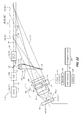
- a range imaging LIDAR system 10, 10 i incorporates a light source 12 that provides for generating at least substantially monochromatic light 14 , which is projected into the atmosphere 16 as a beam of light 18 through and by associated source optics 20 .
- the source optics 20 may comprise a lens assembly 20' that provides for the width and divergence of the beam of light 18 , and a suitable location of the associated beam waist thereof, so as to illuminate an interaction region 22 within the atmosphere 16 that is detectable by the range imaging LIDAR system 10, 10 i , wherein the beam width within the interaction region 22 establishes the associated transverse spatial resolution limit of the range imaging LIDAR system 10, 10 i .
- the source optics 20 may be configured so as to provide for a pencil-like beam of light 18' having a limited width w and depth d , for example, of circular or elliptical cross-section, so as to limit the associated width w and depth d of the associated interaction region 22 .
- the source optics 20 may be configured so as to provide for a sheet-like beam of light 18" -- for example, using source optics 20 comprising cylindrical optics -- having a limited depth d but an extended width w , for example, so as provide for an associated interaction region 22 with a corresponding extended width w , so as to provide for probing extending regions of the atmosphere 16 .
- a set of receiver optics 24 for example, a telescope 24 ', laterally offset from the beam of light 18 , provides for imaging a portion of the beam of light 18 onto an intermediate image plane 26 , so as to provide for a one-to-one mapping of volumetric elements 28 within the beam of light 18 and corresponding associated regions or points 30 in the intermediate image plane 26 .
- the beam of light 18 illuminates molecules 16' or aerosols 16" of the atmosphere 16 , or a combination thereof, within the interaction region 22 , which in turn scatter the monochromatic light 14 of the beam of light 18.
- the resulting scattered light 32 within the field-of-view 34 of the receiver optics 24 is collected thereby and imaged onto the intermediate image plane 26 .
- the receiver optics 24 is laterally offset from and points towards the beam of light 18, so that the optic axis 36 of the receiver optics 24 is inclined relative to the optic axis 38 of the beam of light 18 at an associated parallax angle ⁇ . Accordingly, each volumetric element 28 of the beam of light 18 imaged onto a corresponding region or point 30 on the intermediate image plane 26 corresponds to a different nominal range R from the intermediate image plane 26 to a point 40 on the optic axis 38 of the beam of light 18 associated with the corresponding volumetric element 28. Accordingly, each region or point 30 on the intermediate image plane 26 , corresponding to the volumetric element 28 of the beam of light 18 within the field-of-view 34 of the receiver optics 24 , corresponds to a different nominal range R .
- different regions or points 30 of the intermediate image 42 in the intermediate image plane 26 correspond to different nominal ranges R to the beam of light 18 , and therefore correspond to different nominal ranges R to the associated volumetric elements 28 thereof within the interaction region 22 .
- FIG. 1 For example, as illustrated in FIG. 1
- a closest volumetric element 28.1 of the beam of light 18 within the field-of-view 34 of the receiver optics 24 located at a closest nominal range R MIN from the intermediate image plane 26 is imaged as a corresponding first region or point 30.1 on the intermediate image plane 26
- a farthest volumetric element 28.2 of the beam of light 18 within the field-of-view 34 of the receiver optics 24 located at a farthest nominal range R MAX from the intermediate image plane 26 is imaged as a corresponding second region or point 30.2 on the intermediate image plane 26.
- scattered light 32 from different volumetric elements 28 is imaged onto the intermediate image plane 26 at corresponding different angles of incidence relative thereto.
- the range R to the interaction region 22 is defined by the geometry of the associated beam of light 18 and the corresponding receiver optics 24 .
- the receiver optics 24 can be in focus for one of a plurality of different ranges to the beam of light 18, so that for volumetric elements 28 of the beam of light 18 not in focus, the corresponding images thereof in the intermediate image plane 26, i.e. the corresponding regions or points 30 thereon, will be unfocused and therefore blurred.
- the range R within the interaction region 22 can optionally be further resolved with associated temporal range gating, or range-resolved imaging, of the associated scattered light 32 if desired or necessary for a particular application.
- the range imaging LIDAR system 10, 10 i further comprises a Fabry-Pérot interferometer 44 having an input focal plane 44.1 and an output focal plane 44 . 2 .
- the input focal plane 44.1 is collocated with the intermediate image plane 26 so as to receive scattered light 32 therefrom, which is then processed by the Fabry-Perot interferometer 44 and imaged onto a detection system 46 located at the output focal plane 44.2.
- the Fabry-Pérot interferometer 44 comprises a collimating lens 48, a Fabry-Perot etalon 50 , and imaging optics 52 spaced along an associated common optic axis 53 , wherein the input focal plane 44.1 is a focal plane of the collimating lens 48, the output focal plane 44.2 is a focal plane of the imaging optics 52, and scattered light 32 at the input focal plane 44.1 entering the collimating lens 48 is substantially collimated thereby, then processed by the Fabry-Pérot etalon 50, and finally imaged onto the detection system 46 by the imaging optics 52 .
- the Fabry-Pérot etalon 50 of the Fabry-Pérot interferometer 44 comprises first 54 and second 56 partially-reflective surfaces that are parallel to one another and separated by a fixed gap 58 .
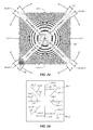
- the angles at which the scattered light 32 is passed through the Fabry-Perot etalon 50 is dependent upon the optical frequency of the scattered light 32 and the length of the gap 58, resulting in an associated scatter fringe pattern 60 comprising a plurality of concentric arcuate fringes 62' -- also known as Haidinger fringes -- in the output focal plane 44.2 of the Fabry-Pérot interferometer 44, for example, as illustrated in FIG. 2 for a fully illuminated Fabry-Pérot interferometer 44.
- the scatter fringe pattern 60 is imaged onto the detection system 46 that generates a scatter electronic image signal 64 responsive thereto which is then processed as described hereinbelow by an associated data processor 66 so as to generate a corresponding set of atmospheric data 68 from information in the scatter fringe pattern 60.
- the Fabry-Pérot etalon 50 comprises a pair of planar optical windows 70 -- for example, constructed of either optical glass or fused quartz -- aligned parallel to and facing one another, and spaced apart from one another by the gap 58 , wherein, for example, the first 54 and second 56 partially-reflective surfaces -- e.g. partially-silvered surfaces or other partially-reflective surfaces -- are on separate facing surfaces of the planar optical windows 70.
- the first 54 and second 56 partially-reflective surfaces could be on the outside opposing faces of the planar optical windows 70 , or one of the first 54 and second 56 partially-reflective surfaces could be on a inner facing surface of one of the planar optical windows 70 , and the other of the first 54 and second 56 partially-reflective surfaces could be on a outer facing surface of the other of the planar optical windows 70 .
- the gap 58 is substantially fixed, whereas in other embodiments, the gap 58 is moveable, e.g. adjustable, for example, using an etalon control actuator 72 responsive to a controller 74 operatively associated with or a part of the data processor 66 , so as to provide for a tunable Fabry-Perot etalon 50 .
- the Fabry-Perot etalon 50 could comprise a solid optical element 76 -- for example, constructed of either optical glass or fused quartz - - with planar parallel faces 78 comprising first 54 and second 56 partially-reflective surfaces separated by a gap 58.1 constituting the length of the solid optical element 76.
- the resulting associated circular fringe pattern 80 is in the form of closed concentric circular fringes 80' centered about the optic axis 53 of the imaging optics 52.
- a typical circular fringe pattern 80 is illustrated in FIG. 2 for an associated scattered light signal 32' that has been source thermally broadened by a medium comprising both aerosols and molecules. The light scattered from the molecules is spread over the shaded regions of the circular fringe pattern 80 in FIG. 2 , and the light scattered from the heavy, slow moving aerosols is contained in the narrow white rings.
- the associated atmospheric state variables affect the circular fringe pattern 80 in different ways.
- Wind induced Doppler shifts change the diameter of the rings, and the constant that determines Doppler shift is dependent upon temperature. Atmospheric (molecular) temperature affects the width of molecular rings. Aerosol density controls the intensity of the narrow white rings and molecular density increases the brightness of the shaded regions in FIG. 2 . Accordingly, wind velocity, density, and temperature can be determined directly from the circular fringe pattern 80 .
- the second region or point 30.2 in the intermediate image plane 26 corresponding to the farthest volumetric element 28.2 is most sharply focused, and the first region or point 30.1 in the intermediate image plane 26 corresponding to the closest volumetric element 28.1 is the most blurred, with the amount of blurring and therefore the associated size of regions or points 30 in the intermediate image plane 26 therebetween increasing with decreasing corresponding associated nominal range R from the second region or point 30.2 to the first region or point 30.1, thereby giving the associated intermediate image 42 of the interaction region 22 of the beam of light 18 a wedge-shaped profile.
- the associated collimating lens 48 and imaging optics 52 provide for imaging the intermediate image plane 26 onto the output focal plane 44.2 that is detected by the detection system 46. Accordingly, the first 30.1 and second 30.2 regions or points on the intermediate image plane 26 -- corresponding to the closest 28.1 and farthest 28.2 volumetric elements of the beam of light 18 within the field-of-view 34 of the receiver optics 24 - are imaged as corresponding first 82.1 and second 82.2 regions or points on the output focal plane 44.2.
- the arcuate fringes 62' of the scatter fringe pattern 60 are present for those regions or points 82 for which the associated frequency or wavelength of the associated scattered light 32 in cooperation with the gap 58 of the Fabry-Pérot etalon 50 provide for constructive interference, whereas arcuate nulls 84 in the scatter fringe pattern 60 are present for those regions or points 82 for which the associated frequency or wavelength of the associated scattered light 32 in cooperation with the gap 58 of the Fabry-Pérot etalon 50 provide for destructive interference.
- Locations of the arcuate fringes 62' are determined by the frequency or wavelength of the associated scattered light 32, the gap 58 of the Fabry-Pérot etalon 50 and the angle of incidence in the Fabry-Pérot etalon 50.
- FIG. 4 illustrates a simulation of a resulting scatter fringe pattern 60 for a solid Fabry-Pérot etalon 50 having a thickness, or gap 58 . 1 , of 0 . 7 cm and an associated reflectivity of 0.85.
- FIG. 5a illustrates a plot of the intensity of the scatter fringe pattern 60 along a section thereof through the optic axis 53 as a function of distance in the output focal plane 44 .
- the nominal range R for which the intermediate image 42 and the associated scatter fringe pattern 60 are in focus can be set to improve the sharpness of the associated range resolution at any particular nominal range R , for example, either using an associated fixed focal setting, or using a focus control actuator 86 responsive to a signal from the controller 74.
- the locations of the arcuate fringes 62' and associated arcuate nulls 84 can be changed by either changing the gap 58 of the Fabry-Pérot etalon 50 , for example, by the etalon control actuator 72 responsive to a signal from the controller 74 , or by tilting the Fabry-Pérot etalon 50.
- the gap 58 of the Fabry-Pérot etalon 50 could be repeatedly scanned by the etalon control actuator 72 responsive to a signal from the controller 74 so as to repeatedly generate associated sets of scatter fringe pattern 60 collectively having arcuate fringes 62' associated with all nominal ranges R to the beam of light 18 within the field-of-view 34 of the receiver optics 24, so as to directly provide for associated atmospheric data 68 at any particular nominal range R within the range of associated nominal ranges R from R MIN to R MAX .
- the range imaging LIDAR system 10, 10 i provides for directly detecting light scattered off of either molecules 16' of the atmosphere, aerosols 16" in the atmosphere, or a combination of the two, and provides for directly measuring the density and temperature of the atmosphere 16, and the velocity thereof in the direction of the optic axis 36 of the receiver optics 24 .
- relatively short wavelength light is scattered by molecules 16' of the atmosphere in accordance with Rayleigh scattering.
- Light can also be scattered by aerosols 16 " in the atmosphere in accordance with Mie scattering.
- the range imaging LIDAR system 10, 10 i is therefore responsive to the properties -- e.g. velocity, density and temperature -- of those molecules 16' in the atmosphere giving rise to the associated scattering of the light detected by the range imaging LIDAR system 10, 10 i . Furthermore, the range imaging LIDAR system 10, 10 i can provide for operation in clean air, i.e. in an atmosphere with no more than a negligible amount of aerosols 16 ", depending substantially upon only molecular scatter.
- the frequency scattered light 32 is Doppler shifted, which for a given gap 58 in the associated Fabry-Pérot etalon 50 thereby causes the associated arcuate fringes 62' of the scatter fringe pattern 60 from the Fabry-Pérot interferometer 44 to be shifted to a location for which an associated constructive interference condition is satisfied for the corresponding rays of scattered light 32 entering the Fabry-Pérot interferometer 44 at a given angle from a corresponding given nominal range R .
- the Doppler shift in the frequency of the scattered light 32 will depend upon the local velocity of the atmosphere 16 within the interaction region 22 interacting with the beam of light 18 , and for different amounts of Doppler shift, arcuate fringes 62' associated with corresponding different nominal ranges R will be generated by the Fabry-Pérot interferometer 44, thereby causing the arcuate fringes 62' to shift within the scatter fringe pattern 60 -- possibly relative to one another depending upon the distribution of velocity of the atmosphere 16 within the interaction region 22.
- the range imaging LIDAR system 10, 10 i further incorporates a filter system 88 to filter the scattered light 32 received by the receiver optics 24 so as to prevent background light from being detected by the detection system 46 .
- the filter system 88 is located within the Fabry-Perot interferometer 44 between the collimating lens 48 and the Fabry-Pérot etalon 50.
- FIG. 1a , 1d and 6 in one set of embodiments, the filter system 88 is located within the Fabry-Perot interferometer 44 between the collimating lens 48 and the Fabry-Pérot etalon 50.
- the filter system 88 incorporates eight bandpass filter mirrors 88' having associated filter pass bands centered about the operating frequency of the light source 12
- the filter system 88 exhibits high out-of-band rejection, as well as low in-band attenuation, and the bandwidth of the filter system 88 is sufficiently narrow so as to substantially filter or remove components of solar radiation or stray light in the collected scattered light 32, yet sufficiently broad so as to be substantially larger than the bandwidth of the thermally-broadened spectrum in combination with the largest expected associated Doppler shift.
- the filter system 88 is adapted so as to provide for maximum filtering of light frequencies that are outside the frequency band of interest, e.g. greater than about 2 nanometers (nm) above or below the nominal center frequency of the light source 12.
- the Fabry-Pérot interferometer 44 is subject to mechanical defects and thermally induced drift that can be compensated through calibration using a reference beam portion 90 of the substantially monochromatic light 14 extracted from the light source 12 with a beam splitter optic 92 and then input to the Fabry-Pérot interferometer 44 at the intermediate image plane 26 as a reference source 94 .
- the reference source 94 from the beam splitter optic 92 is directed into the Fabry-Pérot interferometer 44 with a mirror 96 .
- the reference beam portion 90 of the monochromatic light 14 extracted from the light source 12 with a beam splitter optic 92 as the reference source 94 is input to fiber optic 98 , for example, using a graded index (GRIN) lens 100 , the output of which is located at the intermediate image plane 26 so as to illuminate the collimating lens 48 of the Fabry-Pérot interferometer 44 therefrom.
- GRIN graded index
- the reference source 94 is input to the Fabry-Pérot interferometer 44 from a location 102 on the intermediate image plane 26 / input focal plane 44.1 that is distinct from the intermediate image 42 of the scattered light 32 , and is processed by the Fabry-Perot interferometer 44 so as to generate a corresponding reference fringe pattern 104 comprising one or more associated arcuate fringes 62" at a corresponding location on the output focal plane 44 . 2 , which is then detected by the detection system 46 so as to generate a corresponding reference electronic image signal 106 responsive thereto, which is then processed as described hereinbelow by the associated data processor 66 together with the scatter electronic image signal 64 associated with the scatter fringe pattern 60 from the scattered light 32 .
- the light source 12 provides for generating a sufficient amount of sufficiently narrow-band monochromatic light 14 so as to provide for a sufficient amount of scattered light 32 so that the resulting scatter fringe pattern 60 is detectable by the detection system 46 with a sufficient signal-to-noise ratio (SNR) so that the resulting atmospheric data 68 determined therefrom is accurate within a given accuracy threshold and provides for an information temporal bandwidth that is within a given temporal bandwidth threshold.
- the light source 12 could comprise one or more lasers, light emitting diodes (LEDs), flash lamps, for example, xenon flash lamps, sodium lamps or mercury lamps.
- the light source 12 may be either continuous or pulsed, and need not necessarily be coherent.
- the output of the light source 12 may be filtered with a filter 108 so as to provide for generating sufficiently monochromatic light 14 so as to enable Doppler shifts in the scattered light 32 to be measured sufficiently accurately so as to provide for resolving velocity sufficiently accurately, i.e. less than a given threshold.
- the particular operating wavelength of the range imaging LIDAR system 10, 10 i is not limiting. For example, any optical wavelength that interacts with that which is being sensed in the associated interaction region 22 may be used.
- the monochromatic light 14 comprises ultraviolet (UV) laser light at a wavelength of about 266 nm that is generated using a laser light source 12.
- UV ultraviolet
- a wavelength of about 266 nm being invisible to the human eye and substantially absorbed by the atmosphere, is beneficial for its stealth, eye safety and molecular scattering properties. There is relatively little natural background light at this frequency due to absorption of most natural 266 nm light by ozone and molecular oxygen.
- Ultraviolet light at about 266 nm is readily absorbed by glass and plastic, such as used in aircraft wind screens, which provides for improved eye safety.
- the particular operating wavelength of the range imaging LIDAR system 10 is not limiting, and it should be understood that any optical wavelength that interacts with that which is being sensed in the associated interaction region 22 may be used.
- a Nd:YAG laser 12.1 can operate at relatively high power levels so as to provide sufficiently intense illumination so as to provide for relatively long range atmospheric sensing applications.
- An Nd:YAG laser 12.1 has a fundamental wavelength of 1064 nm, from which shorter wavelengths/higher frequencies may be generated using one or more harmonic generators operatively associated with or a part of the Nd:YAG laser 12.1.
- a second-harmonic generator could be used to convert the fundamental 1064 nm light to second-harmonic 532 nm light which could then be transformed with either a third- or fourth-harmonic generator to generate associated 355 nm or 266 nm light respectively.
- these second-, third- and/or fourth-harmonic generators may be either incorporated in, free-space coupled to, or coupled with a fiber optic to the Nd:YAG laser 12.1 .
- alternative embodiments of the range imaging LIDAR system 10, 10 i incorporating a Nd:YAG laser 12.1 may be operated at frequencies other than 266 nm, for example, at either the second or third harmonics, respectively, for example, as described in U.S. Patent No. 7,495,774 .
- the arcuate fringes 62', 62" of the scatter 60 and reference 104 fringe patterns are circumferentially ( ⁇ ) or transversely ( Y ) integrated either optically prior to detection, or electronically or by software during or following detection by the detection system 46 , so as to provide for corresponding detected image signals I(X) and I 0 (X) , respectively, that representing the total radiometric counts as a function of radial distance through the corresponding scatter 60 and reference 104 fringe patterns .
- the resulting detected image signals I(X) and I 0 (X) are then processed by the data processor 66 as described hereinbelow so as to generate one or more measures of the atmosphere 16 as a function of nominal range R , or at a particular nominal range R , within the interaction region 22 .
- the detection system 46 may comprise either one- or two-dimensional photodetector arrays, for example, either charge-coupled devices (CCDs) or charge injection devices (CIDs); or corresponding arrays of individual photodetectors, for example, photo-conductive, photo-voltaic, photoemissive, bolometer, or thermopile photodetectors, i.e. generally any device that converts photons to a corresponding electrical signal.
- the particular detection system 46 may be adapted in cooperation with the associated light source 12 so as to provide for increasing the associated signal-to-noise ratio (SNR).
- SNR signal-to-noise ratio
- a relatively high-sensitivity, low-noise, low-bandwidth detectors can be used, so as to provide for a higher signal-to-noise ratio (SNR) than possible with corresponding relatively higher-bandwidth detectors, so as to provide for relatively more precise associated measurements.
- the detection system 46 could comprise a camera with at least one array of concentric circular-segment photodetectors for each of the images being processed.
- the range imaging LIDAR system 10, 10 i incorporates a linear photodetector array or a linear array of photodetectors, wherein, referring to FIG. 4 , each photodetector or photodetector element of the array is sufficiently broad in the Y-direction 110 of the output focal plane 44.2 so as to provide for accumulating all of the photons at a given associated X position, and the each photodetector or photodetector element of the array is sufficiently narrow in the X-direction 112 of the output focal plane 44.2 so as to provide for generating a corresponding one-dimensional scatter electronic image signal 64 with sufficient resolution with respect to X to solve for the associated measurements with sufficient accuracy, i.e.
- the range imaging LIDAR system 10, 10 incorporates a similar linear photodetector array or a linear array of photodetectors, wherein each photodetector or photodetector element of the array is sufficiently broad in the Y'-direction 110 of the output focal plane 44.2 so as to provide for accumulating all of the photons at a given associated X'-position , and the each photodetector or photodetector element of the array is sufficiently narrow in the X'-direction 112 of the output focal plane 44.2 so as to provide for generating a corresponding one-dimensional reference electronic image signal 106 with sufficient resolution with respect to X' to characterize the Fabry-Pérot etalon 50 sufficiently accurately so as to provide for solving for the associated measurements with sufficient accuracy, i
- the range imaging LIDAR system 10, 10 to process both the scatter 60 and reference 104 fringe patterns, the range imaging LIDAR system 10, 10 i incorporates a two-dimensional photodetector array or a two-dimensional array of photodetectors that provide for generating associated two-dimensional scatter 64 and reference 106 electronic image signals that, for example, can then be integrated either electronically; or by a process in the data processor 66 , for example, as described hereinbelow.
- Scattered light signal 32' from each of the associated interaction regions 22 are substantially simultaneously processed together with a reference light signal 105 from the reference fringe pattern 104 so as to provide for calibrating, and maintaining the calibration of, the range imaging LIDAR system 10 , and so as to provide for determining the associated air data products such as the speed, temperature and density of the atmosphere 16 .
- This provides for an inherent self-calibration of the associated measurements or quantities derived therefrom. If wavelength drift of the light source 12 is not otherwise accounted for in the data, then errors can arise when making a measurement of the Doppler shift and resulting wavelength shift of the scattered light signal 32' .
- the range imaging LIDAR system 10 provides for automatically compensating for wavelength drift of the light source 12 from the data because each measurement from a scattered light signal 32' is corrected using a corresponding measurement from the reference light signal 105 associated with the reference source 94.
- the associated detection system 46.1 provides for capturing an image 114 of the scatter 60 and reference 104 fringe patterns in the output focal plane 44.2 of the Fabry-Pérot interferometer 44 .
- the detection system 46.1 comprises an electronic camera, for example, a CCD detection system 46.1' .
- this image 114 is then processed to azimuthally compress the associated scatter 60 and reference 104 fringe patterns into corresponding associated linear scatter 60 L and reference 104 L fringe patterns by an associated binning process to give corresponding linear sets of binned pixels 116 from which the corresponding atmospheric data 68 associated with each of the scattered light signals 32' is then determined by the data processor 66.
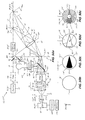
- this process is illustrated in FIGS. 7a and 7b for a range imaging LIDAR system 10, 10 VI " in accordance with an eighth aspect described hereinbelow, comprising four separate scattered fringe patterns 60, 60.1, 60.2, 60.3, 60.4 from four separate corresponding interaction regions 22, interleaved with a reference fringe pattern 104 .
- this is accomplished with a circular binning algorithm implemented in software on the associated data processor 66 operatively coupled to the associated CCD detection system 46.1' that provides for summing all pixels 118 at a particular radius 120 from the common center 122 of the associated circular fringe patterns 80 respectively corresponding to the first 60.1, second 60.2, third 60.3, and fourth 60.4 scatter fringe patterns and the reference fringe pattern 104 interleaved therewith divided into four separate corresponding reference fringe pattern portions 104.1, 104.2, 104.3, 104.4 .
- a circular binning algorithm implemented in software on the associated data processor 66 operatively coupled to the associated CCD detection system 46.1' that provides for summing all pixels 118 at a particular radius 120 from the common center 122 of the associated circular fringe patterns 80 respectively corresponding to the first 60.1, second 60.2, third 60.3, and fourth 60.4 scatter fringe patterns and the reference fringe pattern 104 interleaved therewith divided into four separate corresponding reference fringe pattern portions 104.1, 104.2, 104.3, 104.4 .
- Each pixel 118 is read from the CCD detection system 46.1' and converted by an A/D conversion process.
- the ratio of signal to read noise can be enhanced by increasing the exposure time of the CCD detection system 46.1' between read cycles, although at the cost of reduced dynamic frequency response of the associated resulting air data products.
- the image 114 of the set of circular fringe patterns 80 comprises an array of N rows by M columns of pixels 118 , each of which is captured by the CCD detection system 46.1' and stored in a memory 124 of the associated data processor 66 of the range imaging LIDAR system 10.
- the image 114 comprises eight regions of interest (ROI) 126.1-126.8, each comprising one of the corresponding circular fringe patterns 60.1, 60.2, 60.3, 60.4, 104.1, 104.2, 104.3, 104.4, and located about the common center 122 of the circular fringe patterns 80, wherein the center 122 of the circular fringe patterns 80 is determined upon initial calibration or subsequent recalibration of the associated range imaging LIDAR system 10, and is assumed to be stationary during the operation thereof.
- ROI regions of interest
- the center 122 may be determined by recording a substantial number, e.g. thousands, of circular fringe patterns 80 and determining the location of the center 122 -- by either iteration starting with an initial guess, or least squares or correlation with the coordinates of the center 122 as unknowns to be determined -- that provides for a best fit of the recorded circular fringe patterns 80 with a corresponding circular model thereof centered at the center 122 of the circular fringe patterns 80 .
- step (920) if all of the pixels 118 have been circumferentially binned, then, in step (922), the circumferentially-binned values for each of the circular fringe patterns 80 are returned in the associated bin array BIN(*,NROI). Otherwise, the process repeats with steps (904) and (906) for each of the rows and columns of pixels 118 until all of the circular fringe patterns 80 are binned.
- regions of interest (ROI) 126.1'-126.8' may be defined by the corresponding respective boundaries of the respective circular fringe patterns 80, in which case, step (914) of the circular binning process 900 would be replaced by step (914'), whereby the test as to whether a particular pixel 118 was in a particular regions of interest (ROI) 126.1'-126.8' would depend upon both cylindrical coordinates ( R , ⁇ ) of the particular pixel 118.
- a circular binning process 1000 rather than processing every pixel 118 of the image 114, only those pixels 118 in predefined regions of interest (ROI) 126.1'-126.8' are processed, wherein, for example, the regions of interest (ROI) 126.1'-126.8' are defined by the corresponding respective circular boundaries of the respective circular fringe patterns 80.
- the associated bin elements BIN(*,ROI) are initialized to zero.
- step (1006) the number of pixels 118 in the particular region of interest (ROI) 126.1'-126.8' is given by the predetermined value of N(ROI) .
- step (1008) for pixel m of the N(ROI) pixels 118 in the particular region of interest (ROI) 126.1'-126.8 ' , the corresponding column j and row i indexes for the particular pixel 118 , corresponding to the associated X and Y locations thereof, are given in step (1010) by predetermined values from predetermined index arrays j(m,ROI) and i(m,ROI) respectively, and the corresponding element k of the associated bin array BIN( * ,ROI) into which the particular pixel 118 is to be binned is given by the predetermined index array k(m,ROI).
- step (1014) if all of the pixels m in the particular region of interest (ROI) 126.1'-126.8' have not been binned, then the process continues with step (1008). Otherwise, in step (1016), if all of the regions of interest (ROI) 126.1'-126.8' have not been binned, then the process continues with step (1002). Otherwise, in step (1018), the circumferentially-binned values for each of the circular fringe patterns 80 are returned in the associated bin array BIN(*,NROI).
- the circular fringe patterns 80, 104.1, 104.2, 104.3, 104.4 associated with the reference fringe pattern 104 are binned into a single common linear reference fringe pattern 104 L
- the circular fringe patterns 80, 104.1, 104.2, 104.3, 104.4 associated with the reference fringe pattern 104 are either binned into separate associated linear reference fringe pattern 104 L , 104.1 L , 104.2 L , 104.3 L , 104.4 L , or partially combined into a fewer number of associated linear reference fringe patterns 104 L .
- the range imaging LIDAR system 10, 10 i incorporates a plurality of circle-to-line interferometer optic (CLIO) elements 128 that provide for optically integrating the scatter 60 and reference 104 fringe patterns so as to generate corresponding linearly distributed associated fringe patterns that can then be detected with corresponding linear photodetector arrays or linear arrays of photodetectors, for example, as described hereinabove.
- CLIO circle-to-line interferometer optic
- each circle-to-line interferometer optic (CLIO) element 128 would be used for each circular fringe patterns 80, 60.1, 60.2, 60.3, 60.4, 104.1, 104.2, 104.3, 104.4 on diametrically opposing portions of the Fabry-Pérot interferometer 44 relative to the optic axis 53, wherein each circle-to-line interferometer optic (CLIO) element 128 may be constructed and operated in accordance with the teachings of U.S. Patent No. 4,893,003 , and in accordance with the teachings of U.S. Patent No. 7,495,774 , from line 22 at column 8 through line 50 at column 10 with reference to FIGS. 8 through 15b inclusive therein, and line 54 at column 29 through line 41 at column 30 with reference to FIGS. 35 through 39 inclusive therein.
- the range imaging LIDAR system 10, 10' incorporates a holographic optical element 128' adapted to transform the arcuate fringes 62', 62" into corresponding linear distributions of light, for example, in accordance with the teachings of U.S. Patent No.
- the reference 106 and scatter 64 electronic image signals are transmitted to the data processor 66 , which processes the reference electronic image signal 106 to characterize the Fabry-Pérot etalon 50 , and which then determines one or more range-dependent measures of the atmosphere 16 - at one or more given ranges, or as a function of range -- from the scatter electronic image signal 64 associated with arcuate fringes 62', wherein each arcuate fringes 62' corresponds to a different associated nominal range R and is analyzed separately. More particularly, the scatter electronic image signal 64 provides the information sufficient to determine the following measures of the atmosphere 16: aerosol counts A, molecular counts M, velocity u, temperature t, and background counts B , wherein molecular counts M provides for generating a measure of atmospheric density.
- data from each arcuate fringe 62' is analyzed separately, so as to determine one or more of the measures: aerosol counts A, molecular counts M, velocity u, temperature t , and background counts B either at a given nominal range R or set of nominal ranges R , or as a function of nominal range R.
- the measures are determined by non-linearly fitting the measured reference electronic image signal 106 with a parameterized model of the Fabry-Pérot etalon 50 , parameterized with respect to the measures so as to characterize the Fabry-Pérot etalon 50 , and then non-linearly fitting the measured scatter electronic image signal 64 associated with different arcuate fringes 62' to the parameterized model of the Fabry-Pérot etalon 50, parameterized with respect to the measures to be determined, i.e. with respect to aerosol counts A, molecular counts M, velocity u, temperature t , and background counts B , so as to determine values for those measures at the nominal range R associated with that particular arcuate fringe 62' .
- FIG. Ila A radial plot of the intensity of the circular fringe pattern 80 is illustrated in FIG. Ila.
- a first fringe 130 corresponds to a zero-wind, i.e. zero-velocity condition
- a second fringe 132 corresponds to a non-zero wind condition
- both the first 130 and second 132 fringes are illustrated as exhibiting both an aerosol signal component 130.1, 132.1 and a molecular signal component 130.2, 132.2 respectively.
- the reference light signal 105 also provides for a zero wind condition, but does not contain either molecular or background components, and accordingly would exhibit only the aerosol signal component 130.1 illustrated in FIG. 11b .
- the spectral shape of the scattered light signal 32' processed by the Fabry-Perot etalon 50, for a single associated fringe to be modeled, has a qualitative form illustrated in FIG. 11c , wherein the molecular scattered light, i.e. the molecular component 132.2 , exhibits a broadened spectral shape, while the aerosol scattered light, i.e. the aerosol component 132.1, produces a sharp peak which is nearly identical to the shape of the transmitted laser light. Underlying these two components is a background signal from scattered sunlight, which at the scale of FIG. 11c forms a relatively flat continuum.
- the corresponding spectral shape of the light of the reference light signal 105 processed by the Fabry-Pérot etalon 50 is substantially the same as that of the aerosol component 132.1.
- the range imaging LIDAR system 10 provides for directly detecting laser energy scattered off of either molecules 16' of the atmosphere, aerosols 16" in the atmosphere, or a combination of the two, provides for directly measuring the associated velocity and direction, density, and temperature of the atmosphere, and provides for deriving other measurements therefrom, for example, a set of air data products.
- relatively short wavelength laser energy is scattered by molecules of the atmosphere in accordance with Rayleigh scattering.
- Laser energy can also be scattered by aerosols in the atmosphere in accordance with Mie scattering.
- the range imaging LIDAR system 10 is therefore responsive to the properties -- e.g. velocity, density and temperature -- of those molecules in the atmosphere giving rise to the associated scattering of the light detected by the range imaging LIDAR system 10. Accordingly, the range imaging LIDAR system 10 provides for operation in clean air, i.e. in an atmosphere with no more than a negligible amount of aerosols 16" , depending substantially only upon molecular scatter.
- the image 114 of the scatter fringe pattern 60 generated by the range imaging LIDAR system 10 is modeled use non-linear least square techniques.
- the distribution of the stray light and background radiation is provided by measurements of a fringe pattern 60' either with an associated laser seeder 208 turned off when used yin cooperation with a Nd:YAG laser 12.1 so as to enable the Nd:YAG laser 12.1 to lase over a relatively wider range of wavelengths that provides for simulating background radiation, or with the Fabry-Pérot etalon 50 removed from the Fabry-Pérot interferometer 44.
- the scatter fringe patterns 60 are otherwise measured with the laser seeder 208 turned on if used in cooperation with a Nd: Y AG laser 12.1 so as to provide for substantially single-frequency operation.
- the instrument functions and derivatives used in the algorithm are formed from analytic representations of the Fabry-Pérot interferometer 44 and include the necessary broadening functions to account for defects of the Fabry-Pérot etalon 50, e.g. the associated solid optical element 76 , as well as temperature-dependent line shape broadening from molecular scatter.
- Empirical data for the illumination pattern is also used so that the correct light distribution of the fringes is accurately represented in the models.
- the separation between peaks is known as the free spectral range and depends inversely on the gap 58, 58.1 between the first 54 and second 56 partially-reflective surfaces , so that a relatively large spacing results in a relatively small free spectral range.
- the resolution of a Fabry-Pérot interferometer 44 is determined by the full width at half height (FWHH) of a fringe, which in turn determines the Rayleigh resolving power of the Fabry-Pérot interferometer 44.
- the finesse of the Fabry-Pérot interferometer 44 is a unitless quantity that is defined as the ratio of the Free Spectral Range(FSR) to the FWHH.
- Finesse defines the number of resolvable elements that can fit in between two resonance peaks, and represents the sensitivity of the Fabry-Pérot interferometer 44. In the absence of any defects, the finesse is related primarily to the reflectivity. For example, a reflectivity of 0.80 gives a finesse of 14 , and a reflectivity of 0.90 gives a finesse of 30 . In the presence of defects, both the finesse and the peak transmittance are reduced. Unless careful attention is given to defects when a Fabry-Perot system is designed, the finesse and throughput can be substantially less than anticipated and can adversely bias the measured results.
- M 2 ⁇ ⁇ t ⁇ cos ⁇
- ⁇ is the index of refraction of the material between the first 54 and second 56 partially-reflective surfaces
- t is the effective gap 58, 58.1
- v is the wavenumber of light
- ⁇ is the angle of incidence in the Fabry-Pérot etalon 50 which is responsive to the focal length of the imaging optics 52 and the size of the detection system 46.
- M 2 ⁇ ⁇ ⁇ t 0 ⁇ ⁇ 0 + 2 ⁇ ⁇ ⁇ t 0 ⁇ ⁇ + 2 ⁇ ⁇ ⁇ ⁇ 0 ⁇ ⁇ t - 2 ⁇ ⁇ ⁇ t 0 ⁇ ⁇ 0 ⁇ ⁇ 2 2
- M M o + ⁇ M
- M 0 2 ⁇ ⁇ ⁇ t 0 ⁇ ⁇ 0
- ⁇ M 2 ⁇ ⁇ ⁇ t 0 ⁇ + 2 ⁇ ⁇ ⁇ ⁇ 0 ⁇ t - 2 ⁇ ⁇ ⁇ t 0 ⁇ ⁇ 0 ⁇ ⁇ 2 2
- ⁇ M ⁇ ⁇ ⁇ ⁇ FSR - ⁇ 0 ⁇ ⁇ ⁇ FSR ⁇ ⁇ 2 2 + 2 ⁇ ⁇ ⁇ ⁇ 0 ⁇ ⁇ t
- ⁇ v the Doppler shift
- v 1 the laser wavenumber
- U h the horizontal wind speed in the direction of viewing
- ⁇ the angle from the zenith made by the beam of light 18 as it passes through the atmosphere 16
- U h sin ⁇ the line-of-sight relative wind velocity U .
- equation (22) provides the relationship between line-of-sight relative wind velocity U and the Doppler shift ⁇ v.
- the molecular scattering media broadens the signal due to associated random motions.
- the aerosol broadening function has a Lorentzian form as follows, for example, as described in Fiocco, G., and DeWolf, J.B., "Frequency spectrum of laser echoes from atmospheric constituents and determination of aerosol content of air," Journal of Atmospheric Sciences, v.25, n3, May 1968, pp. 488-496 ; and Benedetti-Michelangeli, G., Congeduti, F., and Fiocco, G., "Measurement of aerosol motion and wind velocity in the lower troposphere by Doppler optical radar," Journal of the Atmospheric Sciences, v.29, n5, July 1972, pp.
- G q can also be utilized in addition to those described hereinabove, for example, so as to account for a defocus of the imaging optics 52.
- the values of the linear sets of binned pixels 116 for the reference light signal 105 and scattered light signals 32' , respectively, provide a corresponding transmission measure T' of the Fabry-Perot interferometer 44 for the corresponding reference light signal 105 and scattered light signals 32' , respectively.
- Each transmission measure T ' is an N-element vector, wherein each element n of the vector corresponds to a different wavelength or corresponding order of interference.
- the element values are in units of measurement counts; for example, with one measurement count being equal to one photoelectron captured by the detection system 46 .
- the transmission measure T ' is a measure of data from the Fabry-Pérot interferometer 44 that can be modeled as described hereinabove in accordance with equations (6) through ( 30 ), as represented by FIGS. 11c and 13 , wherein FIG. 11c illustrates a finer scale of detail of each fringe illustrated in FIG. 13 .
- T Mol (Temp, U) ⁇ MolCounts is the component of transmission T of the Fabry-Pérot interferometer 44 resulting from molecular scatter, which is a function of temperature and line-of-sight relative wind velocity U ;
- T Aero (U) ⁇ AeroCounts is the component of transmission T of the Fabry-Pérot interferometer 44 resulting from aerosol scatter, which is not affected by temperature but is dependent upon the line-of-sight relative wind velocity U ;
- T Back ⁇ BackCounts is the component of transmission T of the Fabry-Pérot interferometer 44 resulting from stray light and background wherein T Back is the continuum distribution or illumination profile through the instrument that is measured during calibration of
- the continuum distributions T Back is obtained from pre-measured values that are stored in memory, and the components T Mol and T Aero are calculated from equation (21) using the appropriate associated broadening terms.
- Each of the above-described components of transmission T of the Fabry-Pérot interferometer 44 is in units of counts resulting from the charge collected by the elements of the detection system 46.
- the distributions T Mol (Temp, U), T Aero (U) are evaluated with equation (21) using broadening functions that are appropriate for the molecular and aerosol components of scatter, respectively.
- the associated infinite series is truncated to ignore higher-order terms of relatively insignificant value, wherein the level of truncation is either predetermined, or determined during the accumulation of the elements of the series.
- the transmission T of the Fabry-Pérot interferometer 44 is modeled with a non-linear model of equation (31) that is parameterized by a first set (or vector) of Parameters P that characterize a particular measurement, i.e. which characterize a particular transmission measure T' ; and a second set of parameters Q which are assumed constant during operation of the Fabry-Pérot interferometer 44, the values of which are determined during calibration.
- the first set of parameters P include the following elements: line-of-sight relative wind velocity U , static temperature Temp, molecular counts MolCounts, aerosol counts AeroCounts , and scatter' counts BackCounts .
- the second set of parameters Q includes the gap 58, 58.1 (t) , index of refraction ⁇ ( 1 for an air gap) and reflectivity R of the Fabry-Pérot etalon 50 , the nominal wavenumber ⁇ (or wavelength ⁇ ) of the monochromatic light 14 from the light source 12 , the focal properties of the imaging optics 52 (i.e. ⁇ in equation (8) ), and the continuum distribution T Rack .
- T'(n) is the value of the n th binned pixel 116'
- T(M(n),P,Q) is the value of the transmission model T from equation (31).
- the transmission model T is overdetermined in the sense that the number of elements N of the detection system 46 , i.e. the number of binned pixels per channel, is of a higher dimension than the number of observables P .
- the number of elements N of the detection system 46 i.e. the number of binned pixels per channel
- ⁇ P l is an vector increment that is to be added to a current approximation for the observable vector P l
- a ⁇ ⁇ P B
- A is the Hessian matrix
- ⁇ P is a vector of increments to the observables that are to be added to a current approximation for the observable P
- B is the gradient vector.
- An iterative process then commences with the solution for ⁇ P of equation (41) , and the evaluation of ⁇ 2 (P+ ⁇ P,Q) . If ⁇ 2 (P+ ⁇ P,Q) ⁇ 2 (PQ) , then ⁇ is increased, e.g. by a factor of 10 , and the iteration is repeated. Otherwise, if ⁇ 2 (P + ⁇ P,Q) ⁇ ⁇ 2 ( P,Q ), then ⁇ is decreased, e.g.
- the observables MolCounts and BackCounts are assumed to be zero valued, and the partial derivatives with respect to MolCounts, BackCounts and Temp of equations (43), (46) and (45) , respectively, are also assumed to be zero.
- the ⁇ 2 (n) weighing term in the ⁇ 2 merit function is the associated variance of the n th measurement channel (i.e. interference order or wavelength), which includes variance of the collected signal in combination with the variance associated with the noise from the detection system 46 .
- the observables P could be estimated using other non-linear modeling or non-linear programming techniques, or other techniques such as non-linear estimation or Kalman filtering.
- the range imaging LIDAR system 10 comprises a laser 12' as the light source 12 , for example, in one embodiment, a Nd:YAG laser 12.1 , which operates in a pulsed mode, and which is operatively associated with a laser seeder 208, for example, a laser diode that provides for seeding the cavity of the pulsed Nd:YAG laser 12.1 with photons via an associated light coupling system, wherein the photons are injected from the laser seeder 208 into the cavity of the Nd:YAG laser 12.1 prior to the build-up of the laser pulse associated of the light source 12 , causing the frequency thereof to substantially match that of the laser seeder 208 , so as to provide for substantially single-frequency operation.
- a laser seeder 208 for example, a laser diode that provides for seeding the cavity of the pulsed Nd:YAG laser 12.1 with photons via an associated light coupling system, wherein the photons are injected from the laser seeder 208 into the cavity of the Nd:
- the laser seeder 208 is adapted in cooperation with the Nd:YAG laser 12.1 so that the bandwidth of the light source 12 is as narrow or narrower than the bandwidth of the associated Fabry-Pérot interferometer 44, wherein the bandwidth of the Fabry-Pérot interferometer 44 is related to the finesse thereof.
- the substantially monochromatic light 14 from the laser 12' is divided by a beam splitter optic 92 into a reference source 94 and the beam of light 18 , the latter of which in some embodiments may be further divided into a plurality of beams of light 18 by beam steering optics 210 , for example, incorporating beam splitting mirrors, prisms, a combination thereof, or some other type of beam splitter, each different beam of light 18 directed in a different direction into the atmosphere 16.
- the scattered light signals 32' and reference source 94 are each first collimated by a collimator 212 , e.g.
- a collimating lens 48 then filtered by a filter system 88 as described hereinabove, and then processed by an associated Fabry-Pérot etalon 50 , the output of which is imaged by associated imaging optics 52 as associated circular fringe patterns 80 onto the associated detection system 46 .
- the associated optical components are adapted for the frequency and power levels of operation. For example, for a range imaging LIDAR system 10 incorporating a Nd:YAG laser 12.1 operating at 355 nanometers, the optical elements would incorporate UV-grade fused silica substrates and standard anti-reflection coatings tuned for 355 nanometers.
- the geometry of the circular fringe patterns 80 from the Fabry-Perot etalon 50 is responsive to the operative gap 58, 58.1 thereof, which would vary with temperature if the associated material or materials controlling the length of the gap 58, 58.1 were to exhibit a non-zero coefficient of thermal expansion.
- the reference source 94 simultaneously processed by the Fabry-Pérot etalon 50 provides for compensating for thermal drift affecting all portions of the Fabry-Pérot etalon 50 equally, it is beneficial if the temperature of the Fabry-Pérot etalon 50 can be controlled or maintained at a constant level so as to prevent a thermal expansion or contraction thereof during the operation thereof.
- the Fabry-Pérot etalon 50 is thermally stabilized by enclosure in a thermally-controlled enclosure 214 so as to prevent thermally-induced drift of the circular fringe pattern 80 .
- the thermally-controlled enclosure 214 is passive, for example, with the Fabry-Pérot etalon 50 enclosed, i.e. thermally insulated or isolated, using a material or materials with a very low thermal conductance to increase the thermal time constant and to prevent any substantial thermal shock from reaching the Fabry-Pérot etalon 50.
- the thermally-controlled enclosure 214 is constructed from a combination of materials adapted so that there is negligible net coefficient of thermal expansion in the portions of the structure surrounding the Fabry-Pérot etalon 50 that affect the length of the gap 58, 58.1.
- a temperature of the thermally-controlled enclosure 214 is actively controlled responsive to at least one associated temperature sensor 216 using a temperature controller 218 incorporating a feedback control system 220 to control a heater, chiller or a combination heater and chiller - depending upon the temperature of the thermally-controlled enclosure 214 in relation to that of its environment.
- a temperature controller 218 incorporating a feedback control system 220 to control a heater, chiller or a combination heater and chiller - depending upon the temperature of the thermally-controlled enclosure 214 in relation to that of its environment.
- the Fabry-Pérot etalon 50 comprises a solid optical element 76 -- for example, constructed from high purity UV grade fused silica -- enclosed within a etalon mount 222 comprising a cylindrical sleeve constructed from a material with a coefficient of thermal expansion that closely matches that of the solid optical element 76 so as to provide for preventing or substantially eliminating unwanted thermally induced radial stress in the solid optical element 76.
- the etalon mount 222 in turn is surrounded by a plurality, e.g.
- thermoelectric cooler segments 224 each having a relatively high thermal conductance-- for example, constructed of copper -- each comprising an inner cylindrical face 226 that abuts an outside surface 228 of the etalon mount 222 , and an outer face 230 incorporating a recess 232 adapted to receive and abut a first surface 234 of a thermo-electric heat pump 236 , for example, what is known as a thermoelectric cooler (TEC).
- TEC thermoelectric cooler
- the heat sink segments 224 collectively constitute an inner enclosure 238 that extends around and surrounds the etalon mount 222 , the latter of which incorporates a flange 240 that abuts a set of first faces 242 on one side of the heat sink segments 224 , and is fastened thereto with a plurality of fasteners 244 , e.g. cap screws.
- the inner enclosure 238 is surrounded by an outer enclosure 246 comprising a plurality, e.g. three, heat conducting outer ring segments 248 , e.g. constructed on aluminum, each of which incorporates an inside face 250 with an associated recess 252 that is adapted to receive and abut a second surface 254 of the thermo-electric heat pump 236.
- Each of the outer ring segments 248 incorporate associated flanges 256 at both ends, one side 258 of which are adapted to cooperate with internal grooves 260 in an outer shell 262 of the thermally-controlled enclosure 214 , the other side 264 of which are adapted to cooperate with an outer ring retainer wedge 266 that operates between corresponding sides 264 of adjacent flanges 256 of adjacent outer ring segments 248 when the outer ring segments 248 are assembled to form the outer enclosure 246 surrounding the inner enclosure 238.
- the inner 238 and outer 246 enclosures are assembled together to form a core assembly 268 , as follows.
- the solid optical element 76 Fabry-Perot etalon 50 is bonded inside a bore 270 of the etalon mount 222 with a thermal epoxy which provides for thermal conduction therebetween, wherein the inside diameter of the bore 270 is adapted so as to provide for a non-interfering fit with the solid optical element 76 .
- the flange 240 of the etalon mount 222 is attached with fasteners 244 to the first faces 242 of the three heat sink segments 224 assembled around the outside surface 228 of the etalon mount 222.
- thermo-electric heat pumps 236 are sandwiched between respective recesses 232 , 252 in a corresponding outer face 230 of each heat sink segment 224 and a corresponding inside face 250 of each outer ring segment 248 , so that the first 234 and second 254 surfaces of the thermo-electric heat pumps 236 abut and are in thermal communication with the corresponding associated heat sink segment 224 and outer ring segment 248 respectively.
- the core assembly 268 further comprises a plurality, e.g. three, temperature sensors 216 , e.g.
- thermocouples each of which is inserted in a corresponding hole 272 in a second face 274 of each heat sink segment 224 , so as to provide for monitoring the temperature thereof, and so as to provide in cooperation with the associated temperature controller 218 and the associated thermo-electric heat pump 236 , for controlling the temperature thereof.
- the core assembly 268 is inserted in the outer shell 262 so that the flanges 240 of the outer ring segments 248 mate with the corresponding internal grooves 260 of the outer shell 262 , and the outer ring retainer wedges 266 are inserted in the gaps 276 between the facing sides 264 of the flanges 240 so as to wedge the opposing sides 258 of the flanges 240 against associated internal grooves 260 of the outer shell 262, thereby providing for retaining the core assembly 268 within the outer shell 262 , and providing for thermal communication therebetween.
- the ends 278 of the outer shell 262 are closed with associated end cap assemblies 280 secured thereto with associated fasteners 282 and sealed therewith with associated seals 284 , e.g.
- the end cap assemblies 280 incorporate associated window assemblies 286 fastened thereto and incorporating optical windows 288 , e.g. constructed from UV grade fused silica substrates with standard anti-reflection coatings, which provide for transmission of the associated scattered 32' and reference 105 light signals .
- the resulting assembly constitutes a thermally stabilized etalon assembly 290 incorporating a thermally-controlled enclosure 214 .
- the thermally stabilized etalon assembly 290 further comprises a plurality of electrical connectors 292 therein which provide for connecting the thermo-electric heat pumps 236 and the temperature sensors 216 with the associated temperature controller 218.
- the temperature controller 218 uses the temperature sensors 216 to monitor the temperature of the core assembly 268 , and controls the heating or cooling thereof relative to the environment using the associated thermo-electric heat pumps 236 so as to maintain the temperature of the core assembly 268 at a specified set-point.
- the outer enclosure 246 in thermal communication with the outer shell 262 provides for either supplying heat to or rejecting heat from the inner enclosure 238 responsive to the thermal effort of the xthermo-electric heat pumps 236 as needed to maintain a particular set-point temperature.
- the set-point temperature is adapted so as to minimize the energy needed to maintain that temperature, while also maintaining a sufficient offset so as to operate the thermo-electric heat pumps 236 most efficiently.
- the set-point temperature might be 5 to 10 degrees Celsius above the nominal environmental temperature, e.g. 5 to 10 degrees Celsius above room temperature.
- the firing of the Nd:YAG laser 12.1 is, for example, controlled with an associated Q-switch in cooperation with a synchronizer 294 , so as to provide for synchronization with the acquisition of associated images by the detection system 46 , thereby precluding the need for an electronic shutter that would otherwise provide for gating scattered 32' and reference 105 light signals to the detection system 46 , although, alternatively, an electronic shutter could also be used or could be used without a synchronizer 294, for example, so as to preclude subsequent imaging during the process of reading image data if using a CCD detection system 46.1'.
- the synchronizer 294, if used, could be incorporated in a control electronics assembly 296, e.g.
- the synchronizer 294 could be adapted to either generate a master timing signal for controlling both the laser 12' and the detection system 46 , or could be adapted to relay a timing pulse generated by either one of the laser 12' and detection system 46 to the other of the detection system 46 and laser 12'.
- the range imaging LIDAR system 10 can take advantage of aerosols when present, but does not rely upon their presence.
- the reference light signal 105 and the scattered light signals 32' of the range imaging LIDAR system 10 can be used to directly measure velocity, true airspeed, vertical speed, angle of attack, angle of sideslip, static density, static temperature, and aerosol to total scattering ratio (ASR). From these data products the following quantities can be directly calculated: calibrated airspeed, Mach number, static pressure, total pressure, dynamic pressure, pressure altitude, air density ratio, total temperature, angle of attack, pressure differential, and angle-of-sideslip pressure differential. Wind velocity, density, and temperature are directly calculated using the fringe data from the Fabry-Pérot interferometer 44.
- the other air data products are derived from these three basic measurements, in view of the knowledge of the associated geometry of the beam steering optics 210 .
- the molecular signal yields a measure of air density that can be related to pressure.
- the aerosol to total scattering ratio is also directly derived from the results.
- the term relative wind is intended to refer to the relative motion between the atmosphere -- included molecules and aerosols -- and the range imaging LIDAR system 10 .
- frequency -- which, responsive to associated Doppler shift, provides for measuring associated velocity -- the algorithm determines the contribution to the fringe pattern from molecular and aerosol scatter, the background radiation, and the temperature of the atmosphere 16 for each particular associated direction associated with each corresponding volumetric element 28 as viewed by the associated receiver optics 24 .
- the relative wind velocity V i is determined along a corresponding direction from a difference between the centroids of the associated scatter fringe pattern 60 associated with a corresponding scattered light signal 32' in comparison with that of the circular fringe pattern 80 associated with the reference light signal 105.
- the fringe position relative to the optic axis 53 is directly related to wavelength. Accordingly, a difference in wavelength between the circular fringe patterns 80 associated with a scattered light signal 32' and that of the circular fringe pattern 80 associated with the reference light signal 105 is a direct measure of the molecular/aerosol Doppler shift in the scattered light 32 from the atmosphere 16 responsive to either molecular or aerosol scattering.
- the relative wind velocity V i for each associated scattered light signal 32' is calculated by subtracting the associated line-of-sight velocity U observable from the corresponding "line-of-sight velocity U" observable of the reference light signal 105, similarly so solved, so as to provide an associated calibrated relative wind velocity V i .
- the air density i.e. static density ⁇
- the density of the atmosphere 16 is related to molecular density, not aerosol density. Accordingly, the Rayleigh scatter is separated from the Mie scatter by spectrally resolving the scattered light and de-convolving the spectrum into associated molecular and aerosol contributions, which provides for determining the density of the atmosphere 16 from the associated molecular component responsive to the total number of photons therein, i.e.
- the absolute temperature, i.e. static temperature T S , of the atmosphere 16 is determined from a width of the molecular signal component 130.2, 132.2 of the circular fringes 80' of the associated circular fringe patterns 80 associated with the scattered light signal 32'.
- the temperature of the atmosphere 16 affects the random thermal motions of the constituent molecules, which causes an associated thermal broadeningreferred to as "Doppler broadening" in the field of spectroscopy because of the random velocities in all directions of an ensemble of molecules -- of the spectrum of the associated scattered radiation, thereby increasing the associated signal bandwidth which produces correspondingly wider fringes in the associated circular fringe patterns 80 from the Fabry-Pérot interferometer 44.
- the absolute temperature of the atmosphere 16 is directly related to this signal bandwidth, and is directly determined as the observable temperature t .
- various other measured air data products may be calculated as follows:
- the relative wind velocities V i determined by the first measurement process 1902 along corresponding associated directions are first transformed from a line-of-sight frame of reference to a frame of reference (x m , y m and z m ) of the range imaging LIDAR system 10 , and then to a frame of reference (x, y, z) of the aircraft 400 using known transformations, so as to provide the relative wind velocities V x , V Y and V Z in the frame of reference (x, y, z ) of the aircraft 400 , from which the true airspeed V T may be calculated from the relative wind velocities V X , V Y and V Z in accordance with a fifth measurement process 1910.
- the vertical speed H' P is given by the Z-component of relative wind velocity V Z .
- the sideslip may be calculated from the Y-component of relative wind velocity V Y and the true airspeed V T in accordance with a sixth measurement process 1912.
- the angle of attack may be calculated from the X and Z-components of relative wind velocity V X and V Z in accordance with a seventh measurement process 1914.
- the Aerosol-to-Total Scattering Ratio (ASR) may also be calculated as the ratio of the observable AeroCounts to the sum of the observables MolCounts, AeroCounts and BackCounts. Referring to FIG.
- the measured values of static density ⁇ , static temperature T S , true airspeed V T , sideslip and angle of attack may then be used to compute the following derived values using associated known relations and processes: air density ratio, static pressure, total pressure, pressure altitude, total temperature, speed of sound, Mach number, dynamic pressure, calibrated airspeed, angle of sideslip pressure differential, and angle of attack pressure differential.
- the Fabry-Pérot etalon 50 is characterized using the reference electronic image signal 106 , wherein the velocity u, molecular counts M and background counts B are all assumed to be zero, as are the partial derivatives with respect to molecular counts M, background counts B and temperature t .
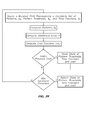
- step (2106) for each arcuate fringe 62', I(X i ) of interest, in step (2106), the associated nominal range R i is given from a pre-determined function or table given the location in the output focal plane 44.2 of the arcuate fringes 62', I(X i ) being analyzed. Then, in step ( 2108 ), given the measurement vector I(X i ) of the arcuate fringe 62', one or more of the atmospheric measures: aerosol counts A, molecular counts M, velocity u, temperature t , and background counts B is solved as described hereinabove.
- step (2110) if all of the arcuate fringes 62', I(X i ) of interest have not been analyzed, then the above process repeats with step (2104). Otherwise, in step (2112) , vectors U , t , M , A , and/or B of the one or more measures for each of the arcuate fringes 62', I(X i ) analyzed in step (2108) are returned, together with a nominal range vector R of associated nominal ranges R , wherein the nominal ranges R i of the nominal range vector will depend upon the associated velocities U i (responsive to Doppler shift), and the gap 58 of the Fabry-Pérot etalon 50.
- These vectors can then be used to either determine functions of one or more measures U(r) , t(r), M(r), A(r * ) or B(r ) as a function of nominal range R , as indicated by step (2114) , or to interpolate values one or more measures U(r * ) , t(r * ), M(r * ), Z(r * ) or B(r * ) at a particular nominal range R* , as indicated by step (2116) .
- the nominal range vector R may be fixed, i.e.
- the range imaging LIDAR system 10, 10 i ' may be built without the collimating lens 48 and input telescope 24'.
- the detector 46' of the detection system 46 located in the output focal plane 44.2 of the imaging optics 52 -- which is where the circular fringes 80' produced by the Fabry-Pérot etalon 50 are sharpest -- when the scattered light signal 32' is relatively close to the sensor, the resulting image 114 of the scatter fringe pattern 60 will be out of focus, but the pertinent information is still present in the image.
- the geometry between the source beam of light 18 and the field-of-view 34 of the receiver optics 24 is essentially the same as the system with the input telescope 24' and collimating lens 48.
- a reference beam portion 90 of the substantially monochromatic light 14 from the light source 12 is reflected from a first beam splitter optic 92 so as to generate an associated reference source 94 which is coupled into an associated fiber optic 98 that routes the signal to where it is needed.
- the output from the fiber optic 98 is divergent and is subsequently collimated by an associated lens 134 and then combined with the scattered light 32 using a second beam splitter optic 136 that reflects a relatively small portion of the substantially monochromatic light 14 from the reference source 94 into the Fabry-Pérot interferometer 44 as the associated reference light signal 105 while transmitting a substantial portion of the scattered light 32 therethrough into the Fabry-Pérot interferometer 44 as the scattered light signal 32'.
- the position of the fiber optic 98 in the image plane of the lens 134 determines where the associated image 114 of the reference light signal 105 will appear on the detection system 46.
- the image 114 of the reference light signal 105 is positioned so as to not overlap the associated scattered light signal 32' in the output focal plane 44.2 of the Fabry-Pérot interferometer 44.
- the image 114 of the reference light signal 105 is positioned so as to overlap the associated scattered light signal 32', with the portion of the reference light signal 105 overlapping the scattered light signal 32' blocked by an associated mask 138 between the lens 134 and the second beam splitter optic 136.
- the associated optics can be designed so that the reference light signal 105 will be sufficient to determine the center of the interference pattern produced by the Fabry-Pérot interferometer 44 as well as the location of the associated arcuate fringes 62', 62".
- the range imaging LIDAR system 10, 10" may be adapted in accordance with a second aspect of an associated detection system 46.2 to measure the overall intensity of the reference source 94 with a detector 140, rather than processing the reference beam through the Fabry-Pérot interferometer 44, for example, so as to provide for either reducing the total number of signals processed with the Fabry-Pérot interferometer 44.
- Such an arrangement would be suitable when the associated atmospheric data 68 being measured therewith are not dependent upon relative wind velocity, the latter of which measure is calibrated responsive to a measure of frequency shift of the reference light signal 105 using the Fabry-Pérot interferometer 44.
- the range imaging LIDAR system 10, 10" illustrated in FIG. 23 would be suitable for measuring either or both of static density p and static temperature T S , or to provide for deriving therefrom one or more of static air pressure, total air temperature, speed of sound, air density ratio or pressure altitude.
- a first embodiment of a third aspect of an associated detection system 46.3, 46.3' of a range imaging LIDAR system 10 incorporates a digital micromirror device (DMD) 142 comprising an array -- for example, a Cartesian array of N rows and M columns-- of associated micromirrors 144, each of which constitutes a controllable pixel 146 that is individually addressable and controllable to one of at least three possible associated pixel mirror rotational states 148, 150, 152.
- DMD digital micromirror device
- the digital micromirror device (DMD) 142 is located in the output focal plane 44.2 of the imaging optics 52 of the Fabry-Pérot interferometer 44 so as to receive the scatter 60 and reference 104 fringe patterns processed by the Fabry-Pérot interferometer 44, portions of which, when processed, are selectively reflected onto a pair of photodetectors 154 A , 154 B , for example, photomultiplier detectors 154 A' , 154 B' , from which complementary signals 156, 158 detected thereby are processed by the data processor 66 so as to provide for determining the associated measures of the atmosphere 16 therefrom as a function of nominal range R.
- the micromirrors 144 of the associated array of micromirrors 144 of the digital micromirror device (DMD) 142 in the first pixel mirror rotational state 148 cause first portions 160' of either the scatter fringe pattern 60 or the reference fringe pattern 104 from the Fabry-Pérot interferometer 44 impinging thereupon to be reflected in a first direction 162 to an associated first objective lens 164, and to be directed thereby to the a first photomultiplier detector 154 A' .
- micromirrors 144 of the associated array of micromirrors 144 of the digital micromirror device (DMD) 142 in the second pixel mirror rotational state 150 cause second portions 160" of either the scatter fringe pattern 60 or the reference fringe pattern 104 from the Fabry-Pérot interferometer 44 impinging thereupon to be reflected in a second direction 166 to an associated second objective lens 168, and to be directed thereby to the a second photomultiplier detector 154 B' .
- micromirrors 144 of the associated array of micromirrors 144 of the digital micromirror device (DMD) 142 in the third pixel mirror rotational state 152 cause third portions 160'" of either the scatter fringe pattern 60 or the reference fringe pattern 104 from the Fabry-Pérot interferometer 44 impinging thereupon to be reflected in a third direction 170 to the light block 172 that provides for absorbing light impinging thereupon.
- the third pixel mirror rotational state 152 corresponds to a state of substantially no rotation of the associated micromirrors 144, which may be achieved, for example, by applying a common voltage to the associated micromirror 144 and it associated mirror address electrodes and yoke address electrodes, so as to create an equal state of electrostatic repulsion between all associated pairs of electrodes associated with the micromirror 144, thereby maintaining the micromirror 144 in a substantially unrotated condition.
- the micromirrors 144 of the digital micromirror device (DMD) 142 are relatively efficient, with overall efficiency approaching 90% in one set of embodiments.
- the digital micromirror device (DMD) 142 provides for digitally isolating light impinging thereupon into two disjoint sets for the portion of the light being analyzed, and for masking a remaining portion of the light.
- the digital micromirror device (DMD) 142 is used to interrogate portions the scatter 60 and reference 104 fringe patterns from the Fabry-Pérot interferometer 44, and in cooperation with the associated first 154 A' and second 154 B' photomultiplier detectors, to provide for generating associated one or more pairs of associated complementary signals 156, 158, each responsive to the number of photons in the associated two disjoint sets of light reflected by the digital micromirror device (DMD) 142 resulting from a particular pattern of pixel mirror rotational states to which the associated array of micromirrors 144 of the digital micromirror device (DMD) 142 are set for a particular set of measurements, wherein the associated first 154 A' and second 154 B' photomultiplier detectors provide for counting the corresponding number of photons associated with each of the disjoint sets of light reflected by the digital micromirror device (DMD) 142.
- one embodiment of the digital micromirror device (DMD) 142 comprises an array of 16 micron square movable micromirrors 144 on 17 micron centers, each micromirror 144 of which is mechanically supported by a yoke 174 suspended from a pair of compliant torsion hinges or flexures 176 operatively coupled to a common CMOS substrate 178.
- Each micromirror 144 is rotatable into one of two stable pixel mirror rotational states responsive to electrostatic attraction between a corner portion 144.1, 144.2 of the micromirror 144 and one of two associated elevated mirror address electrodes 180.1, 180.2, and responsive to electrostatic attraction between a corresponding on of two opposed portions 174.1, 174.2 of the yoke 174 and one of two associated yoke address electrodes 182.1, 182.2.
- the micromirror 144 is rotated to one of the two stable pixel m irror rotational states by applying a first voltage to the micromirror 144 and yoke 174 via a bias-reset bus 184 in electrical connection therewith, and applying a second voltage to one of the mirror address electrodes 180.1, 180.2, and a corresponding one of the yoke address electrodes 182.1, 182.2 , wherein first corresponding mirror 180.1 and yoke 182.1 address electrodes are electrically connected with one another, second corresponding mirror 180.2 and yoke 182.2 address electrodes are electrically connected with one another, and the first and second voltages are set so as to provide for attraction between the first or second mirror 180.1, 180.2 and yoke 182.1, 182.2 address electrodes and corresponding portions of the micromirror 144.1, 144.2 and yoke 174.1, 174.2.
- a second voltage applied to the associated first mirror address electrode 180.1 1 and to the associate first yoke address electrode 182.1 1 causes the first corner portion 144.1 1 of the first micromirror 144 1 to be electrostatically attracted to the associated first mirror address electrode 180.1 1 , and causes the first opposed portion 174.1 1 of the associated yoke 174 1 to be electrostatically attracted to the associated first yoke address electrode 182.1 1 , thereby causing the first micromirror 144 1 to rotate to the first pixel mirror rotational state 148 , which for example, is illustrated in FIG.
- first and second voltages are adapted to provide for an electrostatically attractive force therebetween.
- a third voltage applied to the associated second mirror address electrode 180.2 2 and to the associate second yoke address electrode 182.2 2 causes the second corner portion 144.2 2 of the second micromirror 144 2 to be electrostatically attracted to the associated second mirror address electrode 180.2 2 , and causes the second opposed portion 174.2 2 of the associated yoke 174 2 to be electrostatically attracted to the associated second yoke address electrode 182.2 2 , thereby causing the second micromirror 144 2 to rotate to the second pixel mirror rotational state 150 , which for example, is illustrated in FIG.
- the first and third voltages are adapted to provide for an electrostatically attractive force therebetween.
- the tips 186 of the yoke 174 contact corresponding landing sites 188 on the associated bias-reset bus 184 , and the landing sites 188 may be passivated so as to prevent or reduce stiction, so as to provide for reducing the voltage needed to either reset the micromirror 144 to a flat state, or to rotate the micromirror 144 to the other pixel m irror rotational state.
- Another commercial embodiment for example, provides for mirror rotational states of +/- 10 degrees. In the rest state, the micromirror 144 is flat, but this state is not addressable for individual pixels in one set of commercial embodiments.
- DMD digital micromirror devices
- DMD Commercial digital micromirror devices
- arrays of micromirrors 144 ranging from an array of 640 x 480 micromirrors 144 containing approximately a half million micromirrors 144 in total, to an array of 2048 x 1080 micromirrors 144 containing over two million micromirrors 144 in total.
- Each micromirror 144 of the array represents one pixel 146 of a pattern 190 of associated pixel mirror rotational states 148, 150, 152, wherein each pixel is independently controllable or programmable responsive to a signal from the data processor 66.
- the scattered light signal 32' of the associated scattered light signal 32' received from the interaction region 22 associated with the field-of-view 34 of the telescope 24' is processed by the Fabry-Pérot interferometer 44 to generate an associated scatter fringe pattern 60 that is then separated by the digital micromirror device (DMD) 142 into disjoint portions 60', 60" that are then detected by the corresponding associated first 154 A' and second 154 B' photomultiplier detectors.
- DMD digital micromirror device
- the reference light signal 105 is processed by the same Fabry-Pérot interferometer 44, either simultaneously or sequentially, to generate an associated reference fringe pattern 104 that is then separated by the digital micromirror device (DMD) 142 or a separate corresponding digital micromirror device (DMD) (not illustrated) into disjoint portions 104', 104" that are then detected by the corresponding associated first 154 A' and second 154 B' photomultiplier detectors, or by a separate set of first and second photomultiplier detectors (not illustrated).
- the resulting complementary signals 156, 158 associated with the reference light signal 105 are used to provide for calibrating atmospheric measurements associated with the scattered light signal 32'.
- the range imaging LIDAR system 10 uses the Fabry-Pérot interferometer 44 to directly detect information from the scattered laser energy, wherein the scatter 32' and reference 105 light signals are each detected separately, and information from the reference light signal 105 can then be used to calibrate the associated scattered light signal 32'.
- the detection process is responsive to an incoherent Doppler shift of the laser light scattered by molecules and aerosols in the atmosphere 16 responsive to Rayleigh and Mie scattering respectively.
- the Doppler shift is 2u / c.
- G t 4 ⁇ ⁇ d ⁇ c ⁇ 2 ⁇ A 0 ⁇ kt m
- t is the atmospheric temperature
- k is the Boltzmann constant
- Ao is Avogadro's number
- m molecular mass of the scattering species
- the convolution effects of the optical defects are represented by associated defect coefficients D n,k .
- each of the defect coefficients D n,k would be identically equal to one. However, in a system with optical defects, these may be accounted for in various ways. For example, in accordance with a first method, the defect coefficients D n,k are calibrated using a reference source 94 that does not interact with the atmosphere 16. As long as the range imaging LIDAR system 10 stays calibrated then these defect coefficients D n,k may be used directly in the inversion of data to recover atmospheric state variables.
- a signal from the reference light signal 105 is periodically collected together with one or more associated signals from the corresponding one or more scattered light signals 32', and the effect of the defect coefficients D n,k is computed by de-convolving the ideal signal, H ideal , -- for example, H ideal as given by equation (50.1), -- from the recovered data using the Fourier transform of the ideal signal, H ideal , for example, as given by equations (60.1), (60.2) and (61) described hereinbelow.
- the function G(t) approximates the effect of thermal broadening of a source by a low density gas, which effects are more precisely accounted for by Rayleigh-Brillouin scattering, although that level of detail is not essential to the practice of the range imaging LIDAR system 10.
- I ⁇ A H ⁇ m A + M H ⁇ m M + T 2 1 - R 2 ⁇ B
- I is the total number of photons reaching the photodetector 154
- A is the number of photons that have been scattered by aerosols
- M is the number of photons that have been scattered by molecules
- B is the number of background photons transmitted to the range imaging LIDAR system 10 by the ambient atmosphere
- m A is the molecular mass of an aerosol particle (for example, a very large number on the order of 1.0e5 )
- m M is the molecular mass of air (about 28.92 ).
- FIG. 11a illustrates total fringe response I from equation (52) as a function of radius through the circular fringe pattern 80
- FIGS. 27 and 28 respective illustrate the corresponding partial derivatives thereof with respect to velocity u and temperature t, respectively, as given by equations (53.3) and (53.4), respectively.
- the range imaging LIDAR system 10 provides for sampling, collecting and integrating separate portions, for example, disjoint portions 60', 60", 104', 104", of the scatter 60 and reference 104 fringe patterns, and then using the resulting associated signals, for example complementary signals 156, 158 , for each of a set of different disjoint portions 60', 60", 104', 104" , to determine the values of the variables or parameters characterizing the associated scatter fringe pattern 60.
- the scatter 60 and reference 104 fringe patterns are sampled by the digital micromirror device (DMD) 142, with the pixel mirror rotational states 148, 150, 152 of the associated micromirrors 144 controlled according to a particular pattern 190, so that the micromirrors 144 in the first pixel mirror rotational state 148 provide for reflecting light from a first disjoint portion 60', 104' of the scatter 60 or reference 104 fringe pattern to the first objective lens 164, which focuses the light onto the first photomultiplier detector 154 A' that provides for integrating the light from the first disjoint portion 60', 104' of the scatter 60 or reference 104 fringe pattern so as to generate a first complementary signal 156 ; and so that the micromirrors 144 in the second pixel mirror rotational state 150 provide for simultaneously reflecting light from a second disjoint portion 60", 104" of the scatter 60 or reference 104 fringe pattern to the second objective lens 168 , which focuses the light onto the second photomultiplier detector 154
- This process is repeated for each different set of N different sets of disjoint portions 60', 60" of the scatter fringe pattern 60 , and for one set of disjoint portions 104', 104" of the reference fringe pattern 104, so as to provide for generating N corresponding sets of complementary signals 156, 158, from which up to N different variables or parameters can be characterized.
- FIGS. 1-10 For example, FIGS.
- 29-33 are examples of patterns 190 of pixel mirror rotational states 148, 150, 152 of the micromirrors 144 of the digital micromirror device (DMD) 142 for determining measures of aerosol counts A, molecular counts M, velocity u, temperature t, and background counts B, respectively, as given by the sign of equations (53.1)-(53.5), respectively, wherein the black regions in FIGS. 29-33 are where the value of the corresponding equations (53.1)-(53.5), plus an offset, are negative, for which the associated digital micromirror device (DMD) 142 are controlled to a first pixel mirror rotational state 148 ; and the white regions in FIGS.
- FIGS. 34a -e illustrate radial cross-sections through the corresponding patterns illustrated in FIGS. 29-33 , respectively, from the center of each pattern 190 of pixel mirror rotational states 148, 150, 152, outwards.
- FIG. 29 illustrates an example of the pattern 190, 190.1 of pixel mirror rotational states 148, 150, 152 of the micromirrors 144 of the digital micromirror device (DMD) 142, based upon the sign of the value of equation (53.1), used to obtain a corresponding first set of complementary signals 156.1, 158.1 responsive to a measure of aerosol counts A , wherein the a radial cross-section through the pattern 190, 190.1 of pixel m irror rotational states illustrated in FIG. 29 , from the center thereof outwards, is illustrated in FIG. 34a . Furthermore, FIG.
- FIG. 30 illustrates and example of the pattern 190, 190.2 of pixel mirror rotational states 148, 150, 152 of the micromirrors 144 of the digital micromirror device (DMD) 142, based upon the sign of the value of equation (53.2) , used to obtain a corresponding second set of complementary signals 156.2, 158.2 responsive to a measure of molecular counts M, wherein the a radial cross-section through the pattern 190, 190.2 of pixel m irror rotational states illustrated in FIG. 30 , from the center thereof outwards, is illustrated in FIG. 34b . Yet further, FIG.
- FIG. 31 illustrates and example of the pattern 190, 190.3 of pixel mirror rotational states 148, 150, 152 of the micromirrors 144 of the digital micromirror device (DMD) 142, based upon the sign of the value of equation (53.3) , used to obtain a corresponding third set of complementary signals 156.3, 158.3 responsive to a measure of velocity u, wherein the a radial cross-section through the pattern 190, 190.3 of pixel mirror rotational states 148, 150, 152 illustrated in FIG. 31 , from the center thereof outwards, is illustrated in FIG. 34c . Yet further, FIG.
- FIG. 32 illustrates and example of the pattern 190, 190.4 of pixel mirror rotational states 148, 150, 152 of the micromirrors 144 of the digital micromirror device (DMD) 142, based upon the sign of the value of equation (53.4) , used to obtain a corresponding fourth set of complementary signals 156.4, 158.4 responsive to a measure of temperature t , wherein the a radial cross-section through the pattern 190, 190.4 of pixel mirror rotational states 148, 150, 152 illustrated in FIG. 32 , from the center thereof outwards, is illustrated in FIG. 34d . Yet further, FIG.
- FIG. 33 illustrates and example of the pattern 190, 190.5 of pixel mirror rotational states 148, 150, 152 of the micromirrors 144 of the digital micromirror device (DMD) 142, based upon the sign of the value of equation (53.5), used to obtain a corresponding fifth set of complementary signals 156.5, 158.5 responsive to a measure of temperature t, wherein the a radial cross-section through the pattern 190, 190.5 of pixel mirror rotational states 148, 150, 152 illustrated in FIG. 33 , from the center thereof outwards, is illustrated in FIG. 34e .
- the pattern 190, 190.1 of pixel mirror rotational states 148, 150, 152 used for the measure of aerosol counts A is a subset of the pattern 190, 190.2 of pixel mirror rotational states 148, 150, 152 used for the measure of molecular counts M, and that each of the patterns 190, 190.1-190.5 of pixel mirror rotational states 148, 150, 152 is mathematically independent of the others, so that none of these patterns 190, 190.1-190.5 may be constructed by superposition of the other patterns 190, 190.1-190.5 of pixel mirror rotational states 148, 150, 152.
- the five sets of complementary signals 156.1-156.5, 158.1-158.5 from the first 154 A and second 154 B photodetectors for the circular fringe pattern 80 from the scattered light signal 32' provides sufficient information as necessary to determine aerosol counts A, molecular counts M, velocity u, temperature t, and background counts B therefrom.
- any collection of patterns 190 of pixel mirror rotational states 148, 150, 152 that are spatially independent will work however, not all patterns 190 of pixel mirror rotational states 148, 150, 152 provide the same expected error.
- the optimum selection of patterns 190 of pixel mirror rotational states 148, 150, 152 depends on the variables of interest in the remote sensing problem at hand and also on the state of the solution being sought.
- the patterns 190 of pixel mirror rotational states 148, 150, 152 are chosen in view of an associated model of the optical response of the range imaging LIDAR system 10, wherein the derivatives of the optical response provide for resulting associated complementary signals 156, 158 that are sensitive to changes in the associated variables of interest.
- the patterns 190 may be adapted as with the first aspect, but with the use of an associated threshold when mapping the results of equations (53.1)-(53.5) to the corresponding patterns 190, wherein the patterns 190 are then given responsive whether or not the value of the associated derivative is either greater or less than a chosen threshold, for example, as shown in FIGS. 35 and 36 for two different threshold values -- zero and +30% of signal amplitude, respectively -- as applied to equation (53.3) for partial derivative with respect to velocity u. More particularly, FIG.
- 35 illustrates a pattern 190.3 of pixel mirror rotational states 148, 150, 152 for determining a measure of velocity u superimposed upon the partial derivative of the total fringe response I with respect to velocity u as given by equation (53.3) , for a circular fringe pattern 80 with three orders on the photodetector, and for a threshold of zero, wherein the corresponding pattern 190.3 of pixel mirror rotational states 148, 150, 152 illustrated in FIGS.
- 34c has three positive regions and four negative regions, so that three complete rings of micromirrors 144 would be tilted in a first pixel mirror rotational state 148 towards the first photodetector 154 A and four complete rings would be tilted in a second pixel mirror rotational state 150 toward the second photodetector 154 B .
- the incomplete rings illustrated in FIG. 31 would not be illuminated by the optical source.
- a different value for the threshold would cause some of the regions would grow and others to shrink, for example, as shown in FIG. 36 which illustrates the pattern 190.3 of pixel mirror rotational states 148, 150, 152 for a threshold setting of 0.3 times the associated peak amplitude.
- the partial derivative is a constant, so the associated pattern 190.5 of pixel mirror rotational states 148, 150, 152 is chosen to be spatially independent of the others.
- a pattern 190.5 of pixel mirror rotational states 148, 150, 152 associated with the measure of background counts B could simply divide the radial domain in two by a parameterized proportionality threshold such that all radii above the threshold are imaged onto the first photodetector 154 A and radii below the threshold onto the second photodetector 154.2 B .
- Patterns 190.1, 190.2 and 190.4, respectively, for aerosol counts A, molecular counts M, and temperature t, respectively, can be determined in a similar fashion.
- the programmability of the digital micromirror device (DMD) 142 allows the regions being selected to be varied dynamically as the measurement conditions vary.
- DMD digital micromirror device
- the pattern 190.3 of pixel mirror rotational states 148, 150, 152 for velocity u is most sensitive when its divisions coincide with the fringe peaks (which move with velocity dependent Doppler shifts). Accordingly, real time accuracy can be improved if the pattern 190.3 of pixel mirror rotational states 148, 150, 152 for velocity u were adapted in real time to account for this shift. This ability to adapt the observations can be beneficial in a highly variable natural environment.
- the temporal duration of exposure for each pattern 190 of pixel mirror rotational states 148, 150, 152 may be adjusted within a sample set, i.e. the duration of measurement may be different for different patterns 190 of pixel mirror rotational states 148, 150, 152, so as to provide for re-balancing the sensitivity of the range imaging LIDAR system 10 to increase accuracy in the state variable or state variables of greatest interest.
- temporal exposure weighting and patterns 190 of pixel mirror rotational states 148, 150, 152 depend on the present environmental state and a ranking of the parameters of interest.
- One approach for examining potential systems is by a Monte-Carlo simulation.
- Another is by a non-linear optimization technique such as the Broyden-Fletcher-Goldfarb-Shanno (BFGS) method, a quasi-Newton, variable metric method, for example, as described by J. Nocedal and, S. Wright, Numerical Optimization, Springer-Verlag New York, Inc., 1999, pages 194-201 .
- BFGS Broyden-Fletcher-Goldfarb-Shanno
- variable metric method for example, as described by J. Nocedal and, S. Wright, Numerical Optimization, Springer-Verlag New York, Inc., 1999, pages 194-201 .
- cost function based on the covariance of the minimum variance unbiased estimate - for example, as described by D.
- J ⁇ I ⁇ A ⁇ I ⁇ M ⁇ I ⁇ u ⁇ I ⁇ t ⁇ I ⁇ B which allows the intensity at any phase point, ⁇ , to be approximated as I ⁇ I 0 + J ⁇ ⁇ A , ⁇ M , ⁇ u , ⁇ t , B T
- the expected covariance of the noise in intensity is given by Q .
- this covariance would be a diagonal matrix of the counts collected in each measurement.
- the matrix of dynamics, W is formed by integrating the Jacobean over each pattern 190 of pixel mirror rotational states 148, 150, 152 and applying the corresponding temporal weighting factor.
- ⁇ A , ⁇ M , ⁇ u , ⁇ t , ⁇ B represent the patterns 190 of pixel mirror rotational states 148, 150, 152 that send light to the first photodetector
- ⁇ A , ⁇ M , ⁇ u , ⁇ t , ⁇ B be the complements of these patterns 190 of pixel mirror rotational states 148, 150, 152 which send light to the second photodetector
- the k th row is given by cycling ⁇ k through the set ⁇ A , ⁇ A , ⁇ M , ⁇ u , ⁇ u , ⁇ t , ⁇ t , ⁇ B , ⁇ ⁇ B , ⁇ and similarly for the temporal weighting fractions p k through ⁇ p A ,p A ,p M ,p M ,p u ,p u ,p t ,p t ,p B ,p B ⁇ .
- W k , : p k ⁇ ⁇ ⁇ k ⁇ I ⁇ A d ⁇ , ⁇ ⁇ ⁇ k ⁇ I ⁇ M d ⁇ , ⁇ ⁇ ⁇ k ⁇ I ⁇ u d ⁇ , ⁇ ⁇ ⁇ k ⁇ I ⁇ t d ⁇ , ⁇ ⁇ ⁇ k ⁇ I ⁇ B d ⁇
- Each element of the ⁇ vector represents the expected error in A,M,u,t,B respectively.
- Monte-Carlo analysis to vary the associated thresholds and temporal weighting factors to see how the parameters affect the accuracy of the system, for example, in accordance with the Monte-Carlo procedure is illustrated in FIG. 37 .
- the distribution of the solution space can be understood by viewing the Monte-Carlo results, for example, such as those shown in FIG. 38 , where each point (solution) corresponds to a choice of temporal weightings and pattern thresholds. Such results can aid in choosing a cost function for a descent-based optimization.
- Other more elaborate cost functions may be constructed as well by using any non-negative functional form (such as a Gaussian or logarithmic) such as:
- FIG. 38 shows that there is a trade-off between accurately measuring velocity or temperature.
- the horizontal axis shows the expected error in velocity and the vertical axis shows the expected error in temperature.
- Some solutions work well for velocity determination and others for temperature. Normally, the best solution for velocity is not the best solution for temperature and one must compromise.
- the curve in FIG. 38 labeled "Performance Limit Curve” indicates the performance limit achievable by the system.
- There are many different solutions (weighting schemes and thresholds) in the knee of the curve identified by the circle labeled "Optimal Solutions” which will provide useful answers with expected errors as small as possible. In some cases it may be worthwhile to alternate between several system solutions in order to take turns giving answers that are best for each state of interest.
- any number of schemes could be used to find patterns 190 of pixel mirror rotational states 148, 150, 152 which optimize a cost function.
- the first step of FIG. 37 is changed from "Randomly select pattern thresholds" to "spawn a mutated child representing a candidate set of patterns 190 of pixel mirror rotational states 148 , 150 , 152 (or thresholds) and time fractions", as illustrated in FIG. 39 .
- the patterns 190 of pixel mirror rotational states 148 , 150 , 152 used with the Fabry-Pérot interferometer 44 are not required to be generated without regard to the expected fringe pattern.
- the only requirement is that the patterns 190 of pixel mirror rotational states 148, 150, 152 are algebraically independent, such that no pattern 190 of pixel mirror rotational states 148, 150, 152 can be constructed as a linear combination of the other patterns 190 of pixel mirror rotational states 148, 150, 152 in the set
- an alternative set of patterns 190 of pixel mirror rotational states 148 , 150 , 152 can be generated by dyadic divisions in the radii, similar to a wavelet decomposition.
- the patterns 190 of pixel mirror rotational states 148, 150, 152 do not necessarily have to be radially symmetric. Although the information content of a Fabry-Pérot interferometer 44 is circularly symmetric, if circular symmetry of the selected patterns 190 of pixel mirror rotational states 148, 150, 152 is broken then one may consider the value of the pattern 190 of pixel mirror rotational states 148, 150, 152 for that specific radii to be the fraction (or probability) of pixels in either the first 148 or second 150 pixel mirror rotational states. Such a pattern 190 of pixel mirror rotational states 148, 150, 152 is shown in FIG. 41 where the gray values connote probabilities between 0 and 1 .
- the set of measurements of the complementary signals 156, 158 for the corresponding set of patterns 190 of pixel mirror rotational states 148, 150, 152 can then be used to estimate the parameters or measurements from the range imaging LIDAR system 10 .
- All routines must account for the optical defects in the system as in equations (51.1-51.2). These defects typically have a convolution type response such as a defocus-blurring or an etalon wedge defect. In a Fabry-Perot imaging system one can usually acquire a reference fringe pattern of the laser before it has interacted with the atmosphere. This response will contain all the information necessary to model the system's optical defects and any changes to the Fabry-Pérot etalon 50.
- H ideal H o ( ⁇ )
- the reference signal is also used to track the intensity of the beam and any phase shifts in response due to drift of the gap 58, 58.1 of the Fabry-Pérot etalon 50.
- the refractive index of the Fabry-Pérot etalon 50 may be obtained by independently monitoring the temperature of the Fabry-Pérot etalon 50. This tracking is accomplished in an iterative process using measurements akin to equation (56).
- a similarly related technique is to divide the Fourier Transform coefficients of the reference fringe from the fringe pattern produced by the scattered atmospheric response. The remaining response reveals a phase shift (linearly correlated to the velocity via the expected Doppler shift) and broadening function related to the thermal effects.
- This method is very sensitive to noise in the collected data. More than the five patterns 190.1-190.5 of pixel mirror rotational states 148, 150, 152 already described would be used in order to recover the defect coefficients.
- DMD digital micromirror device
- One method for estimating the parameters of the atmospheric state from the scattered signal is the classic Levenberg-Marquardt nonlinear least squares method which provides for varying smoothly between an inverse-Hessian method and a steepest descent method, as described, along with other suitable non-linear methods, by W.H. Press, S.A. Teukolsky, W.T Vetterling, and B.P. Flannery in Numerical Recipes in C, The Art of Scientific Computing, Second Edition, Cambridge University Press, 1992, pp. 656-661 and 681-706 .
- This method works by iteratively minimizing the mean square error of a set of acquired samples against the output of a forward model (such as the model for the Fabry-Perot transmitted fringe pattern).
- ⁇ k is the standard deviation (in counts) of the k th measurement, namely M k and Q is defined in equation (57).
- One advantage of the range imaging LIDAR system 10 is that the associated ring or pattern parameters can be reconfigured rapidly.
- the micromirrors 144 of the digital micromirror device (DMD) 142 can be reconfigured in about 10 microseconds. This allows the instrument to adapt as the environment changes.
- One other advantage of this type of system is that there is no read noise from the pixels like there is with an imaging photodetector such as a CCD. The only noise is from the first 154 A' and second 154 B' photomultiplier detectors which when cooled produces very low background signals.
- the range imaging LIDAR system 10 uses the molecular response as well as the strong aerosol response which has a very high signal to noise ratio and effectively reduces the system error due to noise; the range imaging LIDAR system 10 can account for and exploit the known effects due to thermal broadening; the range imaging LIDAR system 10 can simultaneously measure velocity, temperature, aerosol and molecular components, and the range imaging LIDAR system 10 can adapt to the changing environment in order to always produce measurements based on the highest sensitivity.
- the first being the relatively low quantum efficiency of the first 154 A' and second 154 B' photomultiplier detectors and the second being the fact that only two of the patterns 190 of pixel mirror rotational states 148, 150, 152 or "ring sets" are being monitored at any given time.
- the second being the fact that only two of the patterns 190 of pixel mirror rotational states 148, 150, 152 or "ring sets" are being monitored at any given time.
- the knowledge of aerosol content might only be required infrequently to provide a reasonable measurement of the Ratio parameter. Temperature is not always required and again could be provided only at infrequent intervals. Accordingly, the basic advantage of the edge type of detection can be achieved with the range imaging LIDAR system 10, and most of the limitations associated with the simple edge detection can be eliminated.
- the range imaging LIDAR system 10 can be employed utilized for any optical remote sensing scenario. Every remote sensing problem is solved by fitting a model for the system response to the data observed while accounting for the expected deviations in the data. In a Fabry-Pérot interferometer 44 system this response is a collection of fringes for which exists a wealth of phenomenological models.
- the range imaging LIDAR system 10 incorporates a digital micromirror device (DMD) 142 in cooperation with a Fabry-Pérot interferometer 44 to segment the optical response between two fast photodetectors.
- DMD digital micromirror device
- segmented measurements are made using patterns 190 of pixel mirror rotational states 148, 150, 152 based on the derivatives of the model with respect to each parameter to be estimated thereby granting the highest sensitivity possible.
- An optimization with respect to segmentation thresholds and timing exposure resolution is performed to minimize the covariance of the minimum variance unbiased estimator of the system. Cost functions based on this covariance may be formed to allow trade-offs to be computed automatically with nonlinear optimization techniques such as BFGS or the Nelder-Mead Simplex algorithm.
- the ability to use fast photodetectors allows one to apply the range imaging LIDAR system 10 to problems where one wishes to measure state variable with a fine spatial resolution.
- DMD digital micromirror devices
- DMD digital micromirror devices
- the patterns 190 of pixel mirror rotational states 148, 150, 152 producing these observations could be optimized in much the same way as described here by simply increasing the number of threshold states used for each derivative.
- an associated detection system 46.3 of a range imaging LIDAR system 10 first calibrates the Fabry-Pérot etalon 50 by analyzing the reference fringe pattern 104, and then generates measures of aerosol counts A, molecular counts M, velocity u, temperature t, and background counts B from the scatter 60 and reference 104 fringe patterns at one or more particular nominal ranges R, or as a function of nominal range R, by parsing the scatter fringe pattern 60 in accordance with the process illustrated in FIG. 21 and described hereinabove and illustrated in FIGS.
- the micromirrors 144 not illuminated thereby are set to the third pixel mirror rotational state 152 so that only light from the reference fringe pattern 104 is then processed as described hereinabove, and the remaining light is reflected to the light block 172 so as to be blocked from detection by the photodetectors 154 A , 154 B .
- the micromirrors 144 not illuminated by the particular arcuate fringe 62' being analyzed at a particular time are set to the third pixel mirror rotational state 152 so that only light from that particular arcuate fringe 62' is then processed as described hereinabove, and the remaining light is reflected to the light block 172 so as to be blocked from detection by the photodetectors 154 A , 154 B .
- a second embodiment of a third aspect of an associated detection system 46.3, 46.3" is the same as for the first embodiment the third aspect of the associated detection system 46.3, 46.3' except that the associated digital micromirror device (DMD) 142 is adapted so that the associated micromirrors 144 thereof are individually addressable and controllable to one of at least two possible associated pixel mirror rotational states 148, 150.
- DMD digital micromirror device
- the micromirrors 144 of the associated array of micromirrors 144 of the digital micromirror device (DMD) 142 in the first pixel mirror rotational state 148 cause first 198' and second 198" portions of either the scatter fringe pattern 60 or the reference fringe pattern 104 from the Fabry-Pérot interferometer 44 impinging thereupon to be reflected in the first direction 162 to the associated first objective lens 164, and to be directed thereby to the a photodetector 154, for example, a photomultiplier detector 154', wherein the first 198' and second 198" portions are sequentially reflected using different associated pixel mirror rotational states 148, 150 of the associated array of micromirrors 144 of the digital micromirror device (DMD) 142 at different times.
- Corresponding associated signals 200, 202 are sampled sequentially, rather than simultaneously - in contradistinction with the first embodiment the third aspect of the associated detection system 46.3, 46.3' for which the associated complementary signals 156, 158 are sampled simultaneously.
- the micromirrors 144 of the associated array of micromirrors 144 of the digital micromirror device (DMD) 142 in the second pixel mirror rotational state 150 cause third portions 198'" of either the scatter fringe pattern 60 or the reference fringe pattern 104 from the Fabry-Pérot interferometer 44 impinging thereupon to be reflected in the second direction 166 to a light block 172 that provides for absorbing light impinging thereupon.
- DMD digital micromirror device
- the first 198' and second 198" portions are sequentially reflected using different associated pixel mirror rotational states 148, 150 of the associated array of micromirrors 144 of the digital micromirror device (DMD) 142 at different times, wherein the first 198' and second 198" portions are relatively disjoint as for the first embodiment the third aspect of the associated detection system 46.3, 46.3', so that the resulting signals 200, 202 correspond to the complementary signals 156, 158 that would otherwise be sampled by the first embodiment the third aspect of the associated detection system 46.3, 46.3'.
- DMD digital micromirror device
- the micromirrors 144 of the digital micromirror device (DMD) 142 associated with the first disjoint portion 60' of the scatter fringe pattern 60, or the first disjoint portion 104' of the reference fringe pattern 104, within the region being processed are set to the first pixel mirror rotational state 148 at a first point in time to measure the first complementary signal 156, and the micromirrors 144 of the digital micromirror device (DMD) 142 associated with the second disjoint portion 60" of the scatter fringe pattern 60, or the second disjoint portion 104" of the reference fringe pattern 104, within the region being processed are set to the first pixel mirror rotational state 148 at a second point in time to measure the second complementary signal 158.
- the micromirrors 144 of the associated array of micromirrors 144 of the digital micromirror device (DMD) 142 outside of the region being processed are set to the second pixel mirror rotational state 150 so as to cause the remaining portion of either the scatter fringe pattern 60 or the reference fringe pattern 104 from the Fabry-Pérot interferometer 44 impinging thereupon to be reflected in the second direction 166 to a stray light block 172' that provides for absorbing light impinging thereupon.
- An additional stray light block 172' is provided to receive stray light reflected from the digital micromirror device (DMD) 142.
- This process is repeated for each of the parameters being detected. Accordingly, a total of 2N measurements are needed in order to identify N parameters using the first aspect of signal processing associated with the second aspect of the second embodiment of a third aspect of an associated detection system 46.3, 46.3".
- N+1 measurements are needed within each region of the scatter 60 or reference 104 fringe patterns to identify N parameters associated with that region, wherein one of the measurements is of the light from the entire region, and the remaining N measurements are for one of the disjoint portions 60', 104' or 60", 104" associated with each of the parameters.
- the signals associated with the remaining disjoint portions 60", 104" or 60', 104' are then found for each parameter by subtracting the corresponding measurement for the one of the disjoint portions 60', 104' or 60", 104" from the corresponding measurement of the total signal 203 for the entire region, or the N parameters are identified by solving a system of equations based upon the N + 1 measurements directly, rather than the corresponding 2N complementary signals.
- the measurement of the total signal 203 for the entire region is made by setting the associated micromirrors 144 of the digital micromirror device (DMD) 142 to the first pixel mirror rotational state 148 at a first point to make a measurement of the total signal 203 from the light of that entire region as one of the first 200 and second 202 signals.
- DMD digital micromirror device
- the micromirrors 144 of the digital micromirror device (DMD) 142 associated with either the first 60', 104' or second 60", 104" disjoint portion within the region being processed is set to the first pixel mirror rotational state 148 at that point in time to measure the other of the first 200 and second 202 signals corresponding to the first 156 or second 158 complementary signal.
- DMD digital micromirror device
- the micromirrors 144 of the associated array of micromirrors 144 of the digital micromirror device (DMD) 142 outside of the region being processed are set to the second pixel mirror rotational state 150 so as to cause the remaining portion of either the scatter fringe pattern 60 or the reference fringe pattern 104 from the Fabry-Pérot interferometer 44 impinging thereupon to be reflected in the second direction 166 to a light block 172 that provides for absorbing light impinging thereupon.
- the remaining second 158 or first 156 complementary signal is then found by subtracting the measured first 156 or second 158 complementary signal from the total signal 203, for each of the N different parameters, or the first 200 and second 202 signals are used directly to solve for the N parameters.
- the method of processing the disjoint portions 60', 60", 104', 104" of the associated scatter 60 and reference 104 fringe patterns, or one of the disjoint portions 60', 60", 104', 104" in combination with the corresponding total signal 203 can also be applied in cooperation with other systems that provide for generating the associated disjoint portions 60', 60", 104', 104" similar to that provided for by one or more digital micromirror devices (DMD) 142 as described hereinabove, but without requiring a digital micromirror device (DMD) 142.
- DMD digital micromirror devices
- a Liquid Crystal Device could be used to generate the associated disjoint portions 60', 60", 104', 104" that are extracted from the associated underlying scatter 60 or reference 104 fringe pattern by controlling the pattern of transmission of associated pixels of the LCD provide for transmitting corresponding selected disjoint portions 60', 60", 104', 104" at any given time. For example, this can be accomplished by replace one of the polarizers normally used in the LCD with a polarization selective beam splitter, wherein the beam splitter provides for a transmission of one polarization while reflecting the other polarization. The output of the LCD would then consist of the selected disjoint pattern and its compliment, one transmitted and the other reflected.
- LCD Liquid Crystal Device
- a Holographic Optical Element could be fabricated that would direct the light from disjoint regions onto individual areas.
- a Holographic Optical Element (HOE) could be constructed that would focus the light from a ring for example onto a single small area where a detector could be located. Separate disjoint areas would direct the light to different detectors which would then be used to detect the light in each disjoint pattern.
- micro-machined mirrors could be fabricated to focus the light in a selected pattern onto a particular region. Detectors located at those regions would then convert the light to an electrical signal that would be measured and processed.
- individual masks could be moved into position to generate the disjoint patterns.
- These masks could be configured around the edge of a disk and the individual masks rotated into position or the masks could be arranged in a linear or two dimensional array, and either a linear or a pair of linear actuators could be used to move the selected masks into position.
- the disjoint portions 60', 60", 104', 104" can be extracted from an electronically captured image 114 of the scatter 60 or reference 104 fringe pattern thator the corresponding regions thereof to be processed corresponding to the associated scattered 32' and reference 105 light signals -- is subsequently compressed by using electronic or software integration or binning as described hereinabove.
- the image 114 may be captured using the first aspect of the associated detection system 46.1, for example, using an electronic camera, for example, a CCD detection system 46.1', from which the corresponding linear scatter 60 L and reference 104 L fringe patterns are for example formed in accordance with the methodology described hereinabove and illustrated in FIGS.
- the range imaging LIDAR system 10, 10 iii is substantially the same as the first aspect of the range imaging LIDAR system 10, 10 i except that the near-range blur in the intermediate image 42 can be reduced by orienting the Fabry-Pérot interferometer 44, and particularly, the collimating lens 48 thereof, in relation to the receiver optics 24 so that the intermediate image plane 26 satisfies the Scheimpflug condition, whereby the optic axis 38 of the beam of light 18, the plane 204 of the effective lens 24" of the receiver optics 24 and the intermediate image plane 26 all interest at a common point of intersection 206, also known as a Scheimpflug intersection.
- Reducing the blur in the intermediate image 42 provides for reducing the breadth of the scatter fringe pattern 60 in the Y-direction 110 in the output focal plane 44.2 , thereby simplifying the requirements of the associated detection system 46 , for example, so as to enable the use of a linear photodetector array or a linear array of photodetectors.
- a range imaging LIDAR system 10, 10 iv is similar to the second embodiment of the first aspect of the range imaging LIDAR system 10, 10 i' illustrated in FIG. 22 but incorporating the first embodiment of the third aspect of an associated detection system 46.3, 46.3' illustrated in FIG. 24a , a collimating lens 48 in cooperation with the Fabry-Pérot interferometer 44 , an input telescope 24' for receiving the scattered light 32 , and with the scattered light 32 and reference source 94 juxtaposed relative to the associated second beam splitter optic 136.
- a substantial portion of the scattered light 32 is reflected from the second beam splitter optic 136 , and the reference light signal 105 from the reference source 94 is transmitted through the second beam splitter optic 136 , wherein the reference source 94 is embodied substantially the same as illustrated and described in accordance with the second embodiment of the first aspect of the range imaging LIDAR system 10,10 i .
- the image 114 of the reference light signal 105 is positioned so as to not overlap the associated scattered light signal 32' in the output focal plane 44.2 of the Fabry-Pérot interferometer 44.
- the image 114 of the reference light signal 105 is positioned so as to overlap the associated scattered light signal 32', with the portion of the reference light signal 105 overlapping the scattered light signal 32' blocked by an associated mask 138 between the lens 134 and the second beam splitter optic 136.
- the light source 12 is pulsed, for example, a pulsed Nd:YAG laser 12.1, and the associated detection system 46 -- for example, using a fast CCD detection system 46.1' instead of the relatively slower DVD-based detection system 46.3 as illustrated -- is sampled in synchronism with the light source 12 so as to provide for initially capturing the reference light signal 105 prior to receiving the scattered light signal 32' , and to then receive the process the scattered light signal 32' thereafter.
- a pulsed Nd:YAG laser 12.1 for example, using a fast CCD detection system 46.1' instead of the relatively slower DVD-based detection system 46.3 as illustrated -- is sampled in synchronism with the light source 12 so as to provide for initially capturing the reference light signal 105 prior to receiving the scattered light signal 32' , and to then receive the process the scattered light signal 32' thereafter.
- a plurality of separate receivers 300, 300.1, 300.2 are adapted to cooperate with a common beam of light 18 , wherein each receiver 300, 300.1, 300.2 comprises an associated combination of receiver optics 24 , a Fabry-Pérot interferometer 44 and a detection system 46 constructed and operated in accordance with any of the above-described aspects of the range imaging LIDAR systems 10 described hereinabove, wherein the reference source 94 associated with each receiver 300, 300.1, 300.2 is obtained from a common beam of light 18.
- the scatter 64 and reference 106 electronic image signals from the receivers 300, 300.1, 300.2 are separately processed by the data processor 66 in accordance with any of the above-described aspects of the range imaging LIDAR systems 10 described hereinabove, and in accordance with the process 2100 illustrated in FIG. 21 , so as to provide for generating a set of one or more measures of aerosol counts A, molecular counts M, velocity u, temperature t, and background counts B at one or more selected nominal ranges R, or as a function of nominal range R, for each of the receivers 300, 300.1, 300.2.
- separate measures of velocity u, u1, u2 at one or more selected nominal ranges R, or as a function of nominal range R are generated for each receiver 300, 300.1, 300.2 , wherein the associated Doppler shift to the frequency of the common beam of light 18 is dependent upon the velocity u of the atmosphere 16 in the direction 301, 301.1, 301.2 of the receiver 300, 300.1, 300.2.
- the separate measures of velocity u, u 1 , u 2 in combination then provide for determining a measure of a velocity vector U at one or more selected nominal ranges R, or as a function of nominal range R, so as to provide for determining a velocity field within the atmosphere 16.
- the fifth aspect of a range imaging LIDAR system 10, 10 v could be used in a wind tunnel to provide for probing the velocity field of the flow field therein without perturbing that flow field.
- a plurality of beams of light 18, 18.1, 18.2, 18.3 are generated from a common light source 12 that is distributed thereto by a corresponding set of beam splitters 302.1, 302.2 and a mirror 304.
- different beams of light 18, 18.1, 18.2, 18.3 may be directed in different directions or at different locations into the atmosphere 16, for example, so as to provide for either probing different portions of the atmosphere, or so as to provide for a velocity vector U of the range imaging LIDAR system 10, 10 vi relative to the atmosphere 16, for example, with the range imaging LIDAR system 10, 10 vi used as an optical air data system in a vehicle, for example, an aircraft.
- the attitude or position of one or more of the beam splitters 302.1, 302.2 and mirror 304 may be controlled by a controller 74 operatively associated with or a part of the data processor 66 so as to provide for controlling the position or orientation of one or more of the associated beams of light 18, 18.1, 18.2, 18.3.
- the range imaging LIDAR system 10, 10 vi may incorporate one or more sets of source optics 20, 20.1, 20.2, 20.3 associated with one or more of the corresponding beams of light 18, 18.1, 18.2, 18.3 so as to provide for shaping the one or more beams of light 18, 18.1, 18.2, 18.3 and setting the size and divergence thereof.
- a plurality of receiver optics 24, 24.1, 24.2, 24.3 are adapted to receive scattered light 32 from corresponding interaction regions 22, 22.1, 22.2, 22.3 of the one or more of the corresponding beams of light 18, 18.1, 18.2, 18.3 within the corresponding fields-of-view 34, 34.1, 34.2, 34.3 of the associated receiver optics 24, 24.1, 24.2, 24.3, wherein each receiver optics 24, 24.1, 24.2, 24.3 is oriented at a corresponding parallax angle ⁇ , ⁇ 1 , ⁇ 2 , ⁇ 3 with respect to the corresponding beam of light 18, 18.1, 18.2, 18.3, so that the associated interaction regions 22, 22.1, 22.2, 22.3 span a substantial range of nominal ranges R.
- Each set of receiver optics 24, 24.1, 24.2, 24.3 is adapted to image the corresponding interaction region 22, 22.1, 22.2, 22.3 at different locations on a common intermediate image plane 26 that is located at the input focal plane 44.1 of a common Fabry-Pérot interferometer 44.
- scattered light 32 from the receiver optics 24, 24.1, 24.2, 24.3 is reflected onto the intermediate image plane 26 by an associated set of mirrors 306.1, 306.2, 306.3.
- a reference beam portion 90 of the substantially monochromatic light 14 is extracted from the light source 12 with a beam splitter optic 92 and then input as a reference source 94 at a location on the intermediate image plane 26 that is distinct from the locations of the intermediate images 82 from each of the receiver optics 24, 24.1, 24.2, 24.3.
- the reference source 94 is processed by the Fabry-Pérot interferometer 44 to generate a corresponding reference fringe pattern 104, and the intermediate images 82 from each of the receiver optics 24, 24.1, 24.2, 24.3 are processed by the Fabry-Pérot interferometer 44 to generate corresponding scatter fringe patterns 60, 60.1, 60.2, 60.3.
- the range imaging LIDAR system 10, 10 vii is adapted to provide for interleaving the scattered 32' and reference 105 light signals in the associated image 114 at the output focal plane 44.2 of the Fabry-Pérot interferometer 44 , for example, as illustrated in FIGS. 7a and 8 for four separate associated scattered fringe patterns 60, 60.1, 60.2, 60.3, 60.4 , although the range imaging LIDAR system 10, 10 vii illustrated in FIG. 47 would provide only two of the four scattered fringe patterns 60, 60.1, 60.2, 60.3, 60.4.
- the seventh aspect of the range imaging LIDAR system 10, 10 vii incorporates a second aspect of a reference source 94' that is used in the eighth aspect of the range imaging LIDAR system 10, 10 viii that is more fully described hereinbelow.
- the second aspect of a reference source 94' uses a rotating diffuser 308 -- driven by a motor 309 -- in cooperation with an integrating sphere 310 so as to provide for substantial angular diversity of the associated reference light signal 105.
- a second beam splitter optic 136 interleaves the reference light signal 105 with associated scattered light signals 32', wherein portions of the reference light signal 105 that would otherwise overlay the scattered light signals 32' are blocked by a first mask 138 prior to combination with the scattered light signals 32' by the second beam splitter optic 136 so that the reference light signal 105 and scattered light signals 32' are disjoint with respect to one another in the resulting image 114.
- the seventh aspect of the range imaging LIDAR system 10, 10 vii comprises a pyramidal image combiner 312 that provides for separating the scattered light signals 32' from one another in the image 114 , for example, uniformly separating the scattered light signals 32' from one another as illustrated in FIGS. 7a and 8 .
- the pyramidal image combiner 312 comprises a plurality of reflective faces 314, each of which provides for reflecting a different scattered light signal 32' into a second mask 316 that is configured to block portions of the scattered light signal 32' that would otherwise overlap the reference light signal 105.
- the range imaging LIDAR system 10, 10 vii incorporates associated beam steering optics 210 comprising a third beam splitter optic 318 that divides the beam of light 18 from the light source 12 into first 18.1 and second 18.2 beams of light that are directed into separate regions of the atmosphere 16 by a series of associated mirrors 320.
- associated beam steering optics 210 comprising a third beam splitter optic 318 that divides the beam of light 18 from the light source 12 into first 18.1 and second 18.2 beams of light that are directed into separate regions of the atmosphere 16 by a series of associated mirrors 320.
- the range imaging LIDAR system 10, 10 vii further incorporates first 24.1 and second 24.1 receiver optics with associated first 36.1 and second 36.2 optic axes directed at separate first 22.1 and second 22.2 interaction regions along the first 18.1 and second 18.2 beams of light within the atmosphere 16 , that provide for receiving corresponding associated first 32.1 and second 32.2 scattered light therefrom that is directed to the corresponding first 314.1 and second 314.2 reflective faces of the pyramidal image combiner 312 by a plurality of associated mirrors 322.
- the reflective faces 314 are flat, whereas in another embodiment the reflective faces 314 are conical circle-to-line interferometer optic (CLIO) elements 128 that also provide for azimuthally compressing the associated resulting scatter fringe patterns 60, 60.1, 60.2.
- the plural scatter fringe patterns 60, 60.1, 60.2, 60.3 generated by the sixth aspect of a range imaging LIDAR system 10, 10 vii illustrated in FIG. 46 are translated with respect to one another in the output focal plane 44.2 of the Fabry-Pérot interferometer 44, whereas referring to FIG. 49 , in accordance with a second aspect, the plural scatter fringe patterns 60, 60.1, 60.2, 60.3 generated by the sixth aspect of a range imaging LIDAR system 10, 10 vi illustrated in FIG. 46 are rotated with respect to one another relative to the optic axis 53 of the Fabry-Pérot interferometer 44.
- the separate arcuate fringes 62' of each of the scatter fringe patterns 60, 60.1, 60.2, 60.3 are separately processed by the data processor 66 in accordance with any of the above-described methods so as to provide for generating a set of one or more measures of aerosol counts A, molecular counts M, velocity u, temperature t, and background counts B at one or more selected nominal ranges R, or as a function of nominal range R, for each of the interaction region 22, 22.1, 22.2, 22.3 within the associated fields-of-view 34, 34.1, 34.2, 34.3 of the associated receiver optics 24, 24.1, 24.2, 24.3.
- the range imaging LIDAR system 10, 10 viii' is similar to the third aspect of the range imaging LIDAR system 10, 10 iii illustrated in FIG. 43 but instead incorporating the second aspect of the reference source 94' and explicitly incorporating the first aspect of the associated detection system 46.1.
- the reference beam portion 90 emanating from the first beam splitter optic 92 is directed therefrom to a reference illuminator 324 , for example, comprising an associated rotating diffuser 308 in combination with an integrating sphere 310 relatively located behind and illuminating the mask 138, 138.1.
- the rotating diffuser 308 produces the phase diversity necessary to reduce the speckle in the reference beam thus providing uniform illumination.
- the reference illuminator 324 provides for generating a uniform and diffuse reference beam 90', for example, as illustrated in FIG. 50b , which is then directed through a first aspect of a mask 138, 138.1 that blocks a portion of the uniform and diffuse reference beam 90' from transmission therethrough, resulting in a corresponding first embodiment of a masked reference beam 90.1" that is then reflected of a partially reflective surface 136.1 of a second beam splitter optic 136, then through and collimated by the collimating lens 48 of the Fabry-Pérot interferometer 44, through the associated filter system 88 , then through the associated Fabry-Pérot etalon 50, and finally through the associated imaging optics 52 of the Fabry-Pérot interferometer 44.
- the scattered light signal 32' is transmitted through the second beam splitter optic 136, then through and collimated by the collimating lens 48 of the Fabry-Perot interferometer 44 , through the associated filter system 88 , then through the associated Fabry-Pérot etalon 50 , and finally through the associated imaging optics 52 of the Fabry-Pérot interferometer 44.
- the imaging optics 52 in cooperation with the collimating lens 48 provides for generating an image 114" of the masked reference beam 90.1" in the output focal plane 44.2 of the Fabry-Pérot interferometer 44, wherein a corresponding image of the mask 138, 138.1 is illustrated in FIG.
- the mask 138, 138.1 comprises an opaque region 138' and a remaining transparent region 138" , wherein the opaque region 138' is sized so as to correspond in profile -- in the output focal plane 44.2 of the Fabry-Pérot interferometer 44 -- to the image 114' of the associated scattered light signal 32'.
- a hypothetical image in the output focal plane 44.2 of the Fabry-Pérot interferometer 44 absent the associated Fabry-Pérot etalon 50 illustrates the disjoint regions 326, 328 therein of the image 114' of the scattered light signal 32' and the image 114" of the masked reference beam 90.1", respectively.
- the mask 138, 138.1 is configured and aligned so as to provide for masking all of the light from the uniform and diffuse reference beam 90' for which the image thereof at the output focal plane 44.2 of the Fabry-Pérot interferometer 44 would otherwise overlap the corresponding image 114' of the scattered light signal 32'. Accordingly, within the output focal plane 44.2 of the Fabry-Pérot interferometer 44 , the light within the region 326 associated with the image 114' of the scattered light signal 32' is exclusively from the scattered light 32, and light associated with the remaining region 328 of the output focal plane 44.2 is exclusively from the uniform and diffuse reference beam 90'.
- the reference illuminator 324 that provides for illuminating the mask 138 could be implemented in various ways.
- the rotating diffuser 308 may be replaced with a scanning mirror that would scan a narrow laser beam across the inside of the integrating sphere 310.
- the integrating sphere 310 could be replaced by either single or multiple diffusers.
- optics could be employed to provide for a uniform illumination of the mask 138.
- the Fabry-Pérot interferometer 44 generates two sets of fringes in the output focal plane 44.2, i.e. focal plane, of the imaging optics 52 as follows: a first set of fringes 330 of an associated reference fringe pattern 104 in the region 328 associated with the uniform and diffuse reference beam 90' , and a second set of fringes 332 of a scatter fringe pattern 60 in the region 326 associated with the scattered light signal 32', wherein each set of fringes 330, 332 is generated responsive to a transmission function of the Fabry-Pérot etalon 50.
- the uniform and diffuse reference beam 90' provides an illumination pattern that is uniform and sufficient in extent so as to fully illuminate the first set of fringes 330 that fall on the detection system 46, 46.1. Otherwise, the first 330 and second 332 sets of fringes are processed as described hereinabove in accordance with any of the above-described aspects of the range imaging LIDAR system 10.
- the range imaging LIDAR system 10, 10 viii may be expanded with additional sets of receiver optics 24, either with one or more associated beams of light 18, in cooperation with a common Fabry-Pérot interferometer 44, -- for example, similar to the fifth through seventh aspects of the range imaging LIDAR system 10, 10 v-vii illustrated in FIGS. 45-47 , but using the reference illuminator 324, mask 138 and second beam splitter optic 136 of the first embodiment of an eighth aspect of range imaging LIDAR system 10, 10 viii as illustrated in FIG. 50a .
- the scatter fringe patterns 60, 60.1, 60.2, 60.3 and the associated opaque regions 138 i' , 138 ii' and 138 iii' of the associated mask 138, 138.1 can be arranged in various orientations relative to one for processing by the Fabry-Pérot interferometer 44.
- FIG. 51a illustrates an example of a mask 138, 138.1 a with three opaque regions 138 i ', 138 ii' and 138 iii' used with a range imaging LIDAR system 10, 10 viii.a with three scatter signal channels for which, referring to FIG. 51b , the associated three distinct scatter fringe patterns 60, 60.1, 60.2, 60.3 are translated with respect to one another, and with one of the scatter fringe patterns 60.2' flipped with respect to the other two scatter fringe patterns 602.1', 60.3' , in the output focal plane 44.2 of the Fabry-Perot interferometer 44 , wherein relative to the first embodiment of the eighth aspect of the range imaging LIDAR system 10, 10 viii illustrated in FIG.
- FIG. 51a corresponds in location to FIG. 50c and FIG. 51b corresponds in location to FIG. 50e .
- the mask 138, 138.1 a is configured (i.e. sized and shaped) and aligned so as to provide for masking all of the light from the uniform and diffuse reference beam 90' for which the image thereof at the output focal plane 44.2 of the Fabry-Pérot interferometer 44 would otherwise overlap the corresponding image 114' of the scattered light signals 32.1', 32.2', 32.3'.
- the light within the region 326 of the image 114' of the scattered light signals 32.1', 32.2', 32.3' is exclusively from the associated scattered light 32 thereof, and light associated with the remaining region 328 of the output focal plane 44.2 is exclusively from the uniform and diffuse reference beam 90'.
- FIG. 52a illustrates an example of a mask 138, 138.1 b with three opaque regions 138 i' , 138 ii' and 138 iii' used with a range imaging LIDAR system 10, 10 viiii.b with three scatter signal channels for which, referring to FIG. 52b , the associated three distinct scatter fringe patterns 60, 60.1, 60.2, 60.3 are rotated with respect to one another and intersecting one another so that each spans a substantial portion of the diametrical image space in the output focal plane 44.2 of the Fabry-Pérot interferometer 44 , wherein relative to the first embodiment of the eighth aspect of the range imaging LIDAR system 10, 10 viii illustrated in FIG. 50a , FIG.
- FIG. 52a corresponds in location to FIG. 50c and FIG. 52b corresponds in location to FIG. 50e .
- the mask 138, 138.1 b is configured (i.e. sized and shaped) and aligned so as to provide for masking all of the light from the uniform and diffuse reference beam 90' for which the image thereof at the output focal plane 44.2 of the Fabry-Pérot interferometer 44 would otherwise overlap the corresponding image 114' of the scattered light signals 32.1', 32.2', 32.3'.
- the light within the region 326 of the image 114' of the of the scattered light signals 32.1', 32.2', 32.3' is exclusively from the associated scattered light 32 thereof, and light associated with the remaining region 328 of the output focal plane 44.2 is exclusively from the uniform and diffuse reference beam 90'.
- FIG. 53a illustrates an example of a mask 138, 138.1 c with three opaque regions 138 i' , 138 ii' and 138 iii' used with a range imaging LIDAR system 10, 10 viii.c with three scatter signal channels for which, referring to FIG. 53b , the associated three distinct scatter fringe patterns 60, 60.1, 60.2, 60.3 are rotated with respect to one another, each separated from one another, extending radially outwards from the optic axis 53 of the imaging optics 52, wherein relative to the first embodiment of the eighth aspect of the range imaging LIDAR system 10, 10 viii illustrated in FIG. 50a , FIG. 53a corresponds in location to FIG. 50c and FIG.
- the mask 138, 138.1 c is configured (i.e. sized and shaped) and aligned so as to provide for masking all of the light from the uniform and diffuse reference beam 90' for which the image thereof at the output focal plane 44.2 of the Fabry-Pérot interferometer 44 would otherwise overlap the corresponding image 114' of the scattered light signals 32.1', 32.2', 32.3'.
- the light within the region 326 of the image 114' of the of the scattered light signals 32.1', 32.2', 32.3' is exclusively from the associated scattered light 32 thereof, and light associated with the remaining region 328 of the output focal plane 44.2 is exclusively from the uniform and diffuse reference beam 90'.
- the separate arcuate fringes 62' of each of the scattered fringe patterns 60, 60.1, 60.2, 60.3 are separately processed by the data processor 66 in accordance with the multichannel variations of the eighth aspect of the range imaging LIDAR system 10, 10 viii.a-c described hereinabove so as to provide for generating a set of one or more measures of line-of-sight relative wind velocity U, static temperature Temp, molecular counts MolCounts, aerosol counts AeroCounts, and background counts BackCounts at one or more selected nominal ranges R , or as a function of nominal range R, for each of the interaction regions 22, 22.1, 22.2, 22.3 within the associated fields-of-view 34 of the associated receiver optics 24.
- FIGS. 54a -e there is illustrated a second embodiment of the eighth aspect of the range imaging LIDAR system 10, 10 viii" , that is the same as the second embodiment illustrated in FIGS. 50a -e except that the associated detection system 46 is in accordance with the first embodiment of the third aspect of the detection system 46.3 illustrated in FIGS. 24a and 44 . Accordingly, the associated resulting first 330 and second 332 sets of fringes are processed in accordance with the methodology described hereinabove associated with FIGS. 27-41 , 12 and 19-21.
- FIGS. 55a -e there is illustrated a third embodiment of the eighth aspect of the range imaging LIDAR system 10, 10 viii'" , that is substantially the same as the second embodiment of the eighth aspect of the range imaging LIDAR system 10, 10 viii" described hereinabove, except that the third embodiment of the eighth aspect of the range imaging LIDAR system 10, 10 viii'" incorporates second aspect of a mask system 138' comprising a programmable mask 138.2 that replaces the mask 138, 130.1 of the second embodiment of the eighth aspect of the range imaging LIDAR system 10, 10 viii' , wherein the programmable mask 138.2 comprises a second digital micromirror device (DMD) 334 and an associated second light block 336.
- DMD digital micromirror device
- the second digital micromirror device (DMD) 334 is oriented relative to the reference illuminator 324 and to the second beam splitter optic 136 so that when the associated micromirrors 144 of the second digital micromirror device (DMD) 334 are in a first pixel mirror rotational state 338, light from the uniform and diffuse reference beam 90' incident thereupon is reflected towards the second beam splitter optic 136 and is reflected from the partially reflective surface 136.1 of a second beam splitter optic 136 into to the Fabry-Pérot interferometer 44 , and when the associated micromirrors 144 of the second digital micromirror device (DMD) 334 are in a second pixel mirror rotational state 340 , light from the uniform and diffuse reference beam 90' incident thereupon is reflected towards the second light block 336 and is substantially absorbed thereby.
- the micromirrors 144 of the second digital micromirror device (DMD) 334 that would coincide in location with the opaque region 138' of the first aspect of the mask 138, 138.1 used in the first and second embodiments of the eighth aspect of the range imaging LIDAR system 10, 10 viii' , 10 viii" are set to the second pixel mirror rotational state 340 so as to block the corresponding portions of the uniform and diffuse reference beam 90', and the remaining micromirrors 144 of the second digital micromirror device (DMD) 334 are set to the first pixel mirror rotational state 338 so as to generate a masked reference beam 90.2" that corresponds to the masked reference beam 90.1" of the first and second embodiments of the eighth aspect of the range imaging LIDAR system 10, 10 viii' , 10 viii" .
- the third embodiment of the eighth aspect of the range imaging LIDAR system 10, 10 viii'" functions the same as the second embodiment of the eighth aspect of the range imaging LIDAR system 10, 10 viii" , with FIGS. 55b -e corresponding to FIGS. 54b -e , respectively.
- the various aspects of the range imaging LIDAR system 10 , 10'-10 viii can be used in a variety of applications, including flight control or flight data monitoring, for example, for an aircraft 400 or UAV 402 ; or monitoring atmospheric or weather conditions from an aircraft 400.1 , 400.2 , UAV 402 , balloon 404 , satellite 406 , or ground-based LIDAR system 408.
- the aircraft 400, 400.1 and UAV 402 illustrated in FIG. 56 each incorporate a range imaging LIDAR system 10 that incorporates three lines of sight 36' so as to provide for measuring an associated relative wind vector in addition to other air data products, wherein each line of sight 36' is along the associated optic axis of the corresponding associated receiver optics 24.
- the range imaging LIDAR system 10 can be adapted for airframe applications which, for example, might otherwise incorporate a pitot-static tube for measuring air speed.
- the range imaging LIDAR system 10 provides for optically measuring, or calculating from optical measurements, a substantial quantity of air data products, and can be adapted to detect wind shear, wake vortices, clear air turbulence, and engine stall (unstart) conditions.
- Common air data products include, but are not limited to, Mach number, true airspeed, calibrated airspeed, vertical speed, static density, static air temperature, sideslip, angle of attack, pressure altitude, and dynamic pressure.
- the air data products can be used directly by an aircraft flight computer for flight control purposes.
- the range imaging LIDAR system 10 provides for an airframe-independent design that can be flush-mounted to the skin of the airframe, e.g.
- the range imaging LIDAR system 10 can operate at substantial angles of attack. For example, a properly-configured range imaging LIDAR system 10 can operate at a 90 degree angle of attack.
- the range imaging LIDAR system 10 can be adapted to a variety of airframes, for example, including highly maneuverable aircraft and hoverable aircraft.
- the range imaging LIDAR system 10 provides for an airframe-independent design that can be relatively inexpensive to calibrate, recalibrate or service.
- the aircraft 400, 400.1, 400.2, UAV 402, and balloon 404 illustrated in FIG. 56 each incorporate an range imaging LIDAR system 10 adapted with a plurality of lines of sight 36', so as to provide for substantially simultaneously measuring air data products from one or more interaction regions 22 along each of the associated lines of sight 36'.
- the first aircraft 400.1 incorporates two lines of sight 36' distributed transversely with respect to the associated direction of travel thereof
- the second aircraft 400.2 incorporates five lines of sight 36' distributed transversely with respect to the associated direction of travel thereof, so as to provide for automatically acquiring a substantial amount of atmospheric data (e.g. density, temperature and wind velocity) that can be used for either monitoring or predicting weather, or for monitoring particular emissions into the atmosphere.
- atmospheric data e.g. density, temperature and wind velocity
- the UAV 402 is illustrated with lines of sight 36' substantially along the direction of travel thereof, which can provide for automatically acquiring a substantial amount of atmospheric data (e.g. density, temperature and wind velocity) that, for example, can be used for either monitoring or predicting weather dynamics, or for monitoring the dynamics of particulate emissions into the atmosphere.
- atmospheric data e.g. density, temperature and wind velocity
- the orientation of the plurality of lines of sight 36' relative to the associated vehicle or the associated direction of travel thereof is not limiting, i.e. either other orientations or a combination of orientations may be used.
- the satellite 406 and the ground-based LIDAR system 408 illustrated in FIG. 56 each incorporate an range imaging LIDAR system 10 adapted with a line of sight 36' that is directed respectively downwards or upwards into the atmosphere so as to provide for measuring air data products from one or more interaction regions 22 along each of the associated one or more lines of sight 36', for example, so as to provide for automatically acquiring a substantial amount of atmospheric data (e.g. density, temperature and wind velocity) that can be used for either monitoring or predicting weather, or for monitoring particular emissions into the atmosphere.
- atmospheric data e.g. density, temperature and wind velocity
- the ground-based LIDAR system 408 and associated range imaging LIDAR system 10 may be operatively associated with a gimbal mechanism 410 comprising an azimuthally-rotatable platform 412 which is adapted to pivotally support associated beam steering optics 210 so as to provide for an elevational rotation thereof relative a base 414 to which the azimuthally-rotatable platform 412 is operatively associated.
- a gimbal mechanism 410 comprising an azimuthally-rotatable platform 412 which is adapted to pivotally support associated beam steering optics 210 so as to provide for an elevational rotation thereof relative a base 414 to which the azimuthally-rotatable platform 412 is operatively associated.
- the azimuthally-rotatable platform 412 is adapted to rotate relative to the base 414, for example, responsive to an associated motor drive system, so as to define an associated azimuth angle of the beam steering optics 210
- the beam steering optics 210 is adapted to rotate relative to the azimuthally-rotatable platform 412, for example, responsive to an associated motor drive system, so as to define an associated elevation angle of the beam steering optics 210.
- the range imaging LIDAR system 10 in accordance with any of the above-described aspects 10 i -10 viii can be employed utilized for any optical remote sensing scenario.
- the range imaging LIDAR system 10 could be applied to the detection of Clear Air Turbulence, Optical Air Data systems, Atmospheric Aerosol Characterization, Smog detection and Chemical/Biological Agent detection.
- the range imaging LIDAR system 10 can be used to provide air data for Field Artillery Fire Direction Control, Small Arms Wind correction, Airport Turbulence Monitoring and Ship Navigation velocity/weather monitoring.
- the range imaging LIDAR system 10 can also be used to provide air data for predicting winds for any sporting events in which micro-scale airflow plays a significant role such as golf, football, baseball, etc.
- This range imaging LIDAR system 10 can also be used to provide air data for Wind Farm Site Prospecting, Assessment, and Optimization, Wind Farm Monitoring, Wake Effects Measurement and Analysis Wind Turbine Control, and Weather Forecasting for Wind Farms and Grid Management.
- the range imaging LIDAR system 10 can be mounted on a vehicle or carried by an operator to a location from which artillery is to be fired.
- the range imaging LIDAR system 10 would then measure atmospheric parameters such as wind speed, wind direction, temperature, density, and pressure in the atmospheric volume through which the projectile will be fired.
- These are the standard inputs to contemporary fire direction control systems in use by the military, for example, as described in FM 6-40/MCWP 3-16.4 Tactics, Techniques, and Procedures for FIELD ARTILLERY MANUAL CANNON GUNNERY (Field Manual).
- the circular error probable (CEP) can be reduced and accuracy improved.
- the range imaging LIDAR system 10 can be used to provide measures of wind speed, wind direction, temperature, density, pressure, or the associated wind field around the ship, for ships that obtain their propulsion from the wind.
- racing yachts such as used in the America's Cup, can benefit from knowing the winds near their ship as well as the winds near their competition. This information can be used to provide for trimming sails, deploying wings or aerodynamic propulsion devices, or planning trajectories so as to take maximum advantage of the current wind conditions.
- Recreational users can similarly use information about the winds blowing in the region near their craft.
- the range imaging LIDAR system 10 can provide information about the local winds so as to enable participants to adapt accordingly. For example, a golf player can compensate for or take advantage of local winds, given information about how the wind is blowing over the entire flight path of the ball, or if a wind gust was approaching or would soon dissipate, so as to enable the golfer to either adjust their shot according, or to wait for better conditions. Even if the wind information is not available to the individual players, it would be of benefit to broadcasters in showing the viewing audience a graphic of the winds, a trajectory of the ball, and how the winds affected a particular shot.
- the range imaging LIDAR system 10 can also be of benefit in other sporting venues, such as baseball or football, for example, so as to enable broadcasters to illustrate how a baseball might have been held up by the winds in the stadium, or to show how winds had impacted a pass, punt or field goal in football, to as to enhance the viewing experience for fans. Given information about the winds in the stadium, players could adjust their actions accordingly, for example, when hitting a fly ball or kicking a field goal.
- the range imaging LIDAR system 10 can provide advance information about the wind field of a building so as to provide for wind-responsive or wind-anticipative control of tall buildings that are otherwise subject to sway in strong winds. Most modern tall buildings incorporate some form of damping to control how much the building sways in strong winds.
- the range imaging LIDAR system 10 can provide a predictive component (feed forward) to the associated control loops, so as to provide for improving the performance of these damping systems.
- the range imaging LIDAR system 10 can be used to monitor the wind fields that affect bridges, so as either to provide for an active control of the bridge structure responsive thereto, or to provide for controlling or limiting traffic over the bridge.
- the range imaging LIDAR system 10 can be used to monitor wind conditions along roads in zones where high winds regularly pose a danger to travelers, and provide a real-time alert to motorists who are about to enter these zones.
- the range imaging LIDAR system 10 can be used to detect the presence of fog in fog-prone road zones, and to alert motorists of the presence of fog in advance of entering these zones.
- the range imaging LIDAR system 10 can be used in a portable wind measuring system so as to enable responsible parties to more accurately predict where airborne pollution is headed as well as assisting in the assessment how much the pollution is being dispersed or diluted.
- Local wind mapping along with temperature and pressure measurements would provide input to models for prediction of the Nominal Hazard Zone even when there are no visible aerosols to define the plume.
- the range imaging LIDAR system 10 can be used in a wind tunnel to provide for range resolved airflow measurements within the wind tunnel that can provide density and temperature as well as velocity of the air flow within the wind tunnel at a point, along a line, or within a volume of the wind tunnel, without perturbing the associated flow field, wherein the wind tunnel is used to measure how airflow interacts with the objects being tested therein.
- the range imaging LIDAR system 10 can be used at an airport to enhance airport safety, for example, by providing for detecting clear air turbulence resulting from large aircraft taking off or landing, and to also provide measures of air temperature and density that can affect the lift, and hence performance, of aircraft operating at that airport.
- the range imaging LIDAR system 10 can be used to enhance aircraft safety, for example, by providing for mapping the winds in the vicinity of an aircraft and thus providing the pilot with information that is difficult at best to obtain with other means.
- the range imaging LIDAR system 10 can provide wind information outside of the rotor down wash so as to aid the pilot in maintaining hover in gusty wind conditions.
- the range imaging LIDAR system 10 can provide a measure of cross winds during landing or takeoff, and can be used to detect clear air turbulence during flight.
- the range imaging LIDAR system 10 can provide a measure of the wind field within which the aircraft is operating, and can provide assistance in locating updrafts in order to stay aloft.
- the range imaging LIDAR system 10 provides for measuring wind speed, air temperature and air density, which, for example, for purposes of landing, might not be otherwise be available at some airfields.
- a range imaging LIDAR system 10 can be used support airdrops, for example, by either monitoring the wind field below from the aircraft making the drop so as to determine when to drop the payload, or by monitoring the wind field aloft with a range imaging LIDAR system 10 mounted on the payload so as to provide for adjusting the associated parachute during descent so as to provide for controlling the resulting drop location so that the payload is deposited closer to the desired drop zone than might otherwise be possible.
- the wind field could be monitored from above by an associated aircraft, and the resulting measurements could then be communicated to the payload to provide for controlling one or more associated parachutes or drag chutes accordingly so as to control the resulting drop location.
- a range imaging LIDAR system 10 can be used to characterize the atmosphere.
- a range imaging LIDAR system 10 can be used to provide range resolved measures of velocity, temperature, and density of the atmosphere 16 that can be used by meteorologists and/or by atmospheric scientists, for example, so as to provide for predicting or analyzing the weather.
- a range imaging LIDAR system 10 can be used on ocean and lake buoys and other ocean platforms, for example, site assessment and optimization for off-shore wind farms, oil drilling and production platforms, so as to provide range resolved measures of wind speed and direction, for example, to provide for landing helicopters, to control the location of the platform on the ocean, or to provide a warning for general platform operations in advance of the occurrence of high winds or wind gusts.
- a range imaging LIDAR system 10 in accordance with any of the above-described aspects is illustrated in cooperation with an associated wind turbine 416 so as to provide for measuring atmospheric data 68 associated with the operation of the wind turbine 416, for example, a plurality of velocity, temperature or density measurements at a plurality of ranges R from the wind turbine 416, so as to provide for assessing both immediate and near term atmospheric conditions, the atmospheric data 68 of which can be used to control the wind turbine 416 so as to provide for optimizing the electrical power generated thereby or to prevent wind-caused damage thereto.
- FIG. 57 illustrates a first embodiment for which the associated range imaging LIDAR system 10 is attached to the housing or nacelle 418 of the wind turbine 416
- FIG. 57 illustrates a second embodiment wherein the associated range imaging LIDAR system 10 is mounted withing the housing or nacelle 418 of the wind turbine 416 and is operative from within or through a rotatable portion of the wind turbine 416, for example, from within or through a hollow axle 420 of the wind turbine 416.
- the range imaging LIDAR system 10 compries a plurality of beams of light 18.1, 18.2, 18.3 in a corresponding plurality of different directions, and a corresponding plurality of receiver optics 24, 24.1, 24.2, 24.3 with a correspoinding plurality of lines of sight 36.1', 36.2', 36.3' that in cooperation with the corresponding associated beams of light 18.1, 18.2, 18.3 provide for a plurality of assocaited interaction regions 22.1, 22.2, 22.3, each spanning a range of ranges R, and which collectively provide for measuring a different regions of the atmosphere 16.
- the associated range imaging LIDAR systems 10 are relatively fixed with respect to the wind turbine 416.
- the associated interaction regions 22.1, 22.2, 22.3 could be scanned within the atmosphere 16.
- the associated beams of light 18.1, 18.2, 18.3 and associated receiver optics 24, 24.1, 24.2, 24.3 could be configured to rotate with the wind turbine 416 and thereby scan the associated interaction regions 22.1, 22.2, 22.3 over one or more conical surface paths.
- a ground-based LIDAR system 408 could be used in cooperation with the wind turbine 416 to similarly provide associated atmospheric data 68.
- the range imaging LIDAR systems 10 can be used with any fluid medium that provides for generating detectable scattered light 32 when illuminated with a beam of line 18, including, but not limited to, non-atmospheric gases flowing in a pipe and liquids flowing in pipes, channels or sprays.
- the range imaging LIDAR systems 10 could also be used to measure water flow in pipes or channels, or to provide for measuring the speed of a marine vehicle or the associated conditions of the water upon which or within which the marine vehicle operates.
- any type of interferometer could instead also be used, for example, including but not limited to either a Michelson interferometer and associated variations thereof, a Twyman-Green interferometer or a Fizeau interferometer.
- range imaging LIDAR systems 10, 10 i -10 viii described herein have been illustrated with associated geometries that provide for detecting backscattered scattered light 32, it should be understood that a range imaging LIDAR system 10, 10 i -10 iii could also or alternatively incorporate an assocaited geometry that provides for detecting either transversely scattered light 32, or forward scattered light 32.
- range imaging LIDAR systems 10, 10 i -10 viii described herein have been illustrated as providing for range-responsive measurements responsive to a range R along the optic axis 36 of the receiver optics 24, for example, a range R to the receiver optics 24 or the detection system 46, the range-responsive measurements could also be characterized with respect to a range measured along the optic axis 38 of the beam of light 18, or any other axis, by geometric transformation.
Landscapes
- Physics & Mathematics (AREA)
- Engineering & Computer Science (AREA)
- Electromagnetism (AREA)
- Computer Networks & Wireless Communication (AREA)
- General Physics & Mathematics (AREA)
- Radar, Positioning & Navigation (AREA)
- Remote Sensing (AREA)
- Investigating Or Analysing Materials By Optical Means (AREA)
- Optical Radar Systems And Details Thereof (AREA)
Claims (13)
- Procédé de détection à distance un milieu fluide, en particulier une atmosphère, comprenant:- recevoir la lumière dispersée d'une portion dudit milieu liquide, où ladite lumière dispersée est générée le long d'un premier faisceau (18) de lumière substantiellement monochromatique projetée dans ledit milieu fluide le long d'un premier axe (38), et l'opération de recevoir ladite lumière dispersée est théoriquement le long d'un second axe (36) qui est orienté dans une direction différente relatif audit premier axe (38);- former une image de ladite lumière dispersée par un interféromètre (44), où ladite image de ladite lumière dispersée comprend une première pluralité de franges (62), et chaque frange de ladite pluralité de franges (62) est associée avec une portion différente de ladite portion dudit milieu fluide à un intervalle différent (R);- détecter au moins une portion de ladite image de ladite première pluralité de franges (62) de ladite lumière dispersée pour générer une pluralité correspondante de signaux détectés;- analyser au moins une première frange de ladite première pluralité de franges (62) inclue dans ladite pluralité de signaux détectés pour déterminer au moins une mesure dudit milieu fluide dans une première portion dudit milieu fluide à un premier intervalle; et- analyser au moins une seconde frange de ladite première pluralité de franges (62) inclue dans ladite pluralité de signaux détectés pour déterminer au moins une mesure dudit milieu fluide dans au moins une seconde portion dudit milieu fluide à au moins un second intervalle, où ladite première portion dudit milieu fluide est différente de ladite seconde portion dudit milieu fluide, et ledit premier intervalle est différent dudit second intervalle,où
le procédé comprend de plus:- définir une première fonction comprenant un modèle d'un réponse optique dudit interféromètre (44) basée sur ladite pluralité de franges (62), où ladite première fonction fait incorporer au moins un paramètre sensible audit milieu fluide,- définir au moins une seconde fonction comme un dérivé partiel de ladite première fonction à l'égard d'une correspondant audit au moins un paramètre, où au moins l'un desdits jeux d'opérations de détecter et analyser ladite au moins ladite première frange de ladite première pluralité de franges (62) et détecter et analyser ladite au moins ladite seconde frange de ladite première pluralité de franges (62) est en accord avec un procès d'intégration et de résolution sur les donnés de franges correspondantes de soit ladite au moins ladite première frange de ladite première pluralité de franges (62) soit ladite au moins ladite seconde frange de ladite première pluralité de franges (62), correspondant à une portion correspondante dudit milieu fluide,où ledit procès d'intégration et de résolution comprend:- intégrer sélectivement au moins une portion desdites données de franges correspondantes, où ladite au moins une portion desdites données de franges correspondantes est sélectionné sensible à une valeur de ladite au moins une seconde fonction en relation avec une valeur de seuil correspondante, où ladite au moins une seconde fonction correspond à ladite une correspondant audit au moins un paramètre, et l'opération pour intégrer sélectivement ladite au moins une portion desdites données de franges correspondantes prévoit à générer une valeur de signal intégré correspondant;- répéter l'opération d'intégrer sélectivement ladite au moins une portion desdites données de franges correspondantes pour chaque ledit au moins un paramètre pour être identifié de manière à assurer la génération d'un jeu de valeurs de signaux intégrés, où ledit jeu de valeurs de signaux intégrés comprend soit un jeu de premier et second signaux complémentaires (156, 158) pour chaque ledit au moins un paramètre pour être identifié soit une combinaison d'au moins l'un desdits premier et second signaux complémentaires (156, 158) correspondant à chaque ledit un correspondant audit au moins un paramètre et une valeur de signal intégrée résultant d'une intégration d'une totalité desdites données de franges correspondantes, ledit premier signal complémentaire (156) correspond à ladite valeur de signal intégrée correspondant pour une première portion desdites données de franges correspondantes, pour lesquelles ladite au moins une seconde fonction dépasse une première valeur de seuil, et ledit second signal complémentaire (158) correspond à ladite valeur de signal intégré correspondant pour une seconde portion desdites données de franges correspondantes, pour lesquelles ladite au moins une seconde fonction est moins qu' une seconde valeur de seuil; et- déterminer ledit au moins un paramètre de ladite première fonction associée avec lesdites données de franges correspondantes dudit jeu de valeurs de signaux intégrées, où ladite au moins une mesure dudit milieu fluide dans ladite portion correspondante dudit milieu fluide est sensible audit au moins un paramètre associé avec desdites données de franges correspondantes. - Procédé de détection à distance un milieu fluide selon la revendication 1, comprenant de plus:- recevoir une portion de ladite lumière substantiellement monochromatique d'une source (94) de celui comme source de référence (94); et- détecter ladite source de référence (94), où les opérations d'analyser ladite au moins ladite première frange de ladite première pluralité de franges (62) et analyser ladite au moins ladite seconde frange de ladite première pluralité de franges (62) sont sensibles à au moins un signal de référence correspondant détecté de ladite source de référence (94).
- Procédé de détection à distance un milieu fluide selon la revendication 1, comprenant de plus générer ledit premier faisceau (18) de lumière substantiellement monochromatique et projeter ledit premier faisceau (18) de lumière substantiellement monochromatique dans ledit milieu fluide le long dudit premier axe (38).
- Procédé de détection à distance un milieu fluide selon la revendication 1, où chacune de ladite au moins ladite première frange et ladite au moins ladite seconde frange sont de forme arquée, comprenant de plus la compression azimutale comprimant ladite au moins ladite première frange et ladite au moins ladite seconde frange pour former un motif de frange linéaire associé (60), où l'opération de détection au moins une portion de ladite image de ladite première pluralité de franges (62) comprend détecter au moins une portion dudit motif de franges linéaires associé (60).
- Procédé de détection à distance un milieu fluide selon la revendication 1, où ledit au moins une mesure dudit milieu fluide associé avec au moins l'une desdites première et seconde portions dudit milieu fluide comprend une vitesse dudit milieu fluide, ou
où ladite au moins une mesure dudit milieu fluide associé avec au moins l'une desdites première et seconde portions dudit milieu fluide comprend une température dudit milieu fluide, ou
où ladite au moins une mesure dudit milieu fluide associé avec au moins l'une desdites première et seconde portions dudit milieu fluide comprend une densité dudit milieu fluide. - Procédé de détection à distance un milieu fluide selon la revendication 1, comprenant de plus définir une première fonction comprenant un modèle d'une réponse optique dudit interféromètre (44) basée sur ladite première pluralité de franges (62), où ladite première fonction fait incorporer au moins un paramètre sensible audit milieu fluide, l'opération de détecter ladite image comprend générer un jeu de données d'images sensible à une distribution d'intensité de ladite image, au moins l'une des opérations d'analyser ladite au moins ladite première frange de ladite première pluralité de franges (62) et analyser ladite au moins ladite seconde frange de ladite première pluralité de franges (62) est en accord avec un procédé d'ajustement de fonctions sur les données de franges correspondantes de soit ladite au moins ladite première frange de ladite première pluralité de franges (62) ou soit ladite au moins ladite seconde frange de ladite première pluralité de franges (62), correspondant à une portion correspondante dudit milieu fluide, où ledit procédé d'ajustement de fonctions comprend déterminer ledit au moins un paramètre de ladite première fonction associée avec lesdites données de franges correspondantes de sorte que ladite première fonction au moins fait approximer une portion dudit jeu de données d'images correspondant auxdites données de franges correspondantes, et ladite au moins une mesure dudit milieu fluide dans ladite portion correspondante dudit milieu fluide est sensible audit au moins un paramètre associé avec lesdites données de franges correspondantes.
- Système de détection à distance un milieu fluide, comprenant:- un premier faisceau (18) de lumière substantiellement monochromatique projeté dans le milieu fluide le long d'un premier axe (38);- l'interféromètre (44) configuré pour recevoir la lumière dispersée dudit premier faisceau (18) de lumière substantiellement monochromatique dudit milieu fluide le long d'une portion dudit premier faisceau (18) de lumière substantiellement monochromatique;- au moins l'un d'entre un jeu d'optiques de récepteur (24) et un jeu d'optiques d'image (52), où ledit au moins l'un dudit jeu d'optiques de récepteur (24) et ledit jeu d'optiques d'image (52) comprend un axe optique le long duquel ladite lumière dispersée est reçue, ledit jeu d'optiques de récepteur (24) s'il est présent est opératif entre ledit interféromètre (44) et ladite portion dudit premier faisceau (18) de lumière substantiellement monochromatique, ledit jeu d'optiques d'image (52) est en fonctionnement associé avec, ou une partie dudit interféromètre (44), ledit jeu d'optiques d'image (52) prévoit à générer une image d'une première pluralité de franges (62) à partir dudit interféromètre (44) sensible à ladite lumière dispersée, où ladite image de ladite première pluralité de franges (62) est logée à un plan focal (44) dudit jeu d'optiques d'image (52), et ledit axe optique est orienté dans une direction différente relatif audit premier axe (38); et- au moins un détecteur (46.1) associé en fonctionnement avec ledit jeu d'optiques d'image (52), où ledit au moins un détecteur (46.1) prévoit à détecter ladite image de ladite première pluralité de franges (62), et les différentes franges (62) de ladite première pluralité de franges (62) sont associées avec différentes portions dudit milieu fluide le long de ladite portion dudit premier faisceau (18) de lumière substantiellement monochromatique,caractérisé en ce que
ledit système comprend au moins deux détecteurs (154A, 154B) chacun comprenant au moins un photodétecteur d'un système de détection associé, et ledit système de détection comprend de plus un dispositif digital à micromiroirs (DMD), où ledit dispositif digital à micromiroirs (DMD) comprend une pluralité de micromiroirs (144), chaque micromiroir (144) de ladite pluralité de micromiroirs (144) comprend une surface réfléchissante, la pluralité de micromiroirs (144) comprenant une pluralité de surfaces réfléchissantes qui sont logées substantiellement coïncidant avec ladite image dudit interféromètre (44), chaque micromiroir (144) est positionné dans n'importe laquelle d'une pluralité d'états de rotation pixel-miroir, ledit dispositif digital à micromiroirs (DMD) est configuré en relation audit au moins un détecteur (46.1) de sorte que chacun dudit micromiroir (144) de ladite pluralité de micromiroirs (144) dans au moins l'une de ladite pluralité d'états de rotation pixel-miroir prévoit à réfléchir la lumière de ladite image à l'un correspondant desdits au moins deux photodétecteurs (154A, 154B) pour générer une ou plusieurs paires de signaux complémentaires (156, 158). - Système de détection à distance un milieu fluide selon la revendication 7, comprenant de plus un processeur (66) couplé en fonctionnement auxdits au moins deux détecteurs (154A, 154B) où ledit processeur (66) prévoit à déterminer au moins une mesure dudit milieu fluide dans une première portion dudit milieu fluide sensible à une détection d'une première portion de ladite image de ladite première pluralité de franges (62) par un desdits au moins deux détecteurs (154A, 154B), et ledit processeur (66) prévoit à déterminer au moins une mesure dudit milieu fluide dans une seconde portion dudit milieu fluide sensible à une détection d'une seconde portion de ladite image de ladite première pluralité de franges (62) par un desdits au moins deux détecteurs (154A, 154B).
- Système de détection à distance un milieu fluide selon la revendication 7, où ledit interféromètre (44) comprend un étalon Fabry- Perot en coopération avec ledit jeu d'optiques d'image (52), ledit jeu d'optiques d'image (52) sont logées entre ledit étalon Fabry-Perot et une surface opérative d'un système de détection associé, et ledit système de détection comprend lesdits au moins deux détecteurs (154A, 154B).
- Système de détection à distance un milieu fluide selon la revendication 7, où l'un desdits au moins deux détecteurs (154A, 154B) comprend un imageur ayant une surface opérative substantiellement coïncidente avec ladite image dudit interféromètre (44), et ledit imageur prévoit à générer un signal électronique représentatif de ladite image, où ledit imageur comprend préférablement une camera CCD, et ledit signal électronique généré par ladite caméra CCD comprend une représentation pixélisée de ladite image.
- Système de détection à distance un milieu fluide selon la revendication 7, comprenant de plus un block de lumière, où ladite pluralité d'états de rotation pixel-miroir comprend au moins deux états de rotation pixel-miroir, chaque ledit micromiroir (144) de ladite pluralité de micromiroirs (144) dans une première de ladite pluralité d'états de rotation pixel-miroir prévoit à réfléchir la lumière de ladite image audit un correspondant desdits au moins deux photodétecteurs (154A, 154B), et chaque ledit micromiroir (144) de ladite pluralité de micromiroirs (144) dans une seconde de ladite pluralité d'états de rotation pixel-miroir prévoit à réfléchir la lumière de ladite image audit bloc de lumière.
- Système de détection à distance un milieu fluide selon la revendication 7, comprenant de plus une optique de division de faisceau configuré pour recevoir ledit premier faisceau (18) de lumière substantiellement monochromatique avant d'une interaction de celui avec ledit milieu fluide, où ladite première optique de division de faisceau (96) prévoit à générer une source de référence (94) de ladite lumière substantiellement monochromatique d'une portion dudit premier faisceau (18) de lumière substantiellement monochromatique, ladite lumière substantiellement monochromatique de ladite source de référence (94) est détectée séparément par l'un desdits au moins deux détecteurs (154A, 154B) pour prévoir au moins un signal de référence associé qui est utilisé en coopération avec la détection desdites différentes franges de ladite première pluralité de franges (62) associées avec lesdites différentes portions dudit milieu fluide.
- Système de détection à distance un milieu fluide selon la revendication 12, où ladite lumière substantiellement monochromatique de ladite source de référence (94) est dirigée par ledit interféromètre (44) avant la détection distincte par l'un desdits au moins deux détecteurs (154A, 154B), et ledit jeu d'optiques d'images (52) prévoit à générer une image d'une seconde pluralité de franges (62) à partir dudit interféromètre (44) sensible à ladite lumière substantiellement monochromatique de ladite source de référence (94), où ladite image de ladite seconde pluralité de franges (62) est logée audit plan focal (44) dudit jeu d'optiques d'image (52).
Applications Claiming Priority (3)
| Application Number | Priority Date | Filing Date | Title |
|---|---|---|---|
| US17855009P | 2009-05-15 | 2009-05-15 | |
| US29000409P | 2009-12-24 | 2009-12-24 | |
| PCT/US2010/035046 WO2011016892A2 (fr) | 2009-05-15 | 2010-05-15 | Lidar d'imagerie de distance |
Publications (3)
| Publication Number | Publication Date |
|---|---|
| EP2430392A2 EP2430392A2 (fr) | 2012-03-21 |
| EP2430392A4 EP2430392A4 (fr) | 2014-10-29 |
| EP2430392B1 true EP2430392B1 (fr) | 2015-07-22 |
Family
ID=43544831
Family Applications (1)
| Application Number | Title | Priority Date | Filing Date |
|---|---|---|---|
| EP10806774.5A Active EP2430392B1 (fr) | 2009-05-15 | 2010-05-15 | Lidar d'imagerie de distance |
Country Status (4)
| Country | Link |
|---|---|
| US (1) | US8427649B2 (fr) |
| EP (1) | EP2430392B1 (fr) |
| CN (1) | CN102439393B (fr) |
| WO (1) | WO2011016892A2 (fr) |
Families Citing this family (129)
| Publication number | Priority date | Publication date | Assignee | Title |
|---|---|---|---|---|
| DE102008031681A1 (de) * | 2008-07-04 | 2010-01-14 | Eads Deutschland Gmbh | LIDAR-Verfahren zur Messung von Geschwindigkeiten und LIDAR-Vorrichtung mit zeitgesteuerter Detektion |
| US8810796B2 (en) * | 2009-04-21 | 2014-08-19 | Michigan Aerospace Corporation | Light processing system and method |
| WO2011014712A2 (fr) * | 2009-07-29 | 2011-02-03 | Michigan Aerospace Corporation | Système de mesure atmosphérique |
| WO2014084973A1 (fr) | 2012-11-30 | 2014-06-05 | HAYES, Paul, Byron | Système de mesure atmosphérique |
| FR2951275B1 (fr) * | 2009-10-09 | 2012-11-02 | Epsiline | Dispositif de mesure de la vitesse du vent |
| US10619748B1 (en) * | 2010-09-30 | 2020-04-14 | The United States Of America, As Represented By The Secretary Of The Navy | Phase diversity system and method for producing a corrected image and/or for aiming electromagnetic energy |
| US8913124B2 (en) * | 2011-02-03 | 2014-12-16 | The United States Of America As Represented By The Administrator Of The National Aeronautics And Space Administration | Lock-in imaging system for detecting disturbances in fluid |
| US8736676B2 (en) * | 2011-04-04 | 2014-05-27 | CyPhy Works, Inc. | Imaging based stabilization |
| RU2495452C2 (ru) * | 2011-10-31 | 2013-10-10 | Федеральное государственное бюджетное образовательное учреждение высшего профессионального образования "Российский государственный гидрометеорологический университет" | Способ дистанционного оптического зондирования слабо рассеивающей атмосферы |
| US8908160B2 (en) * | 2011-12-23 | 2014-12-09 | Optical Air Data Systems, Llc | Optical air data system suite of sensors |
| US8938362B2 (en) * | 2012-01-23 | 2015-01-20 | The Aerospace Corporation | Systems, methods, and apparatus for doppler LIDAR |
| US9600863B2 (en) * | 2012-02-13 | 2017-03-21 | Omnivision Technologies, Inc. | Method for combining images |
| CN102608619B (zh) * | 2012-03-07 | 2013-07-24 | 北京航空航天大学 | 光子计数压缩采样相控阵激光三维成像方法 |
| US9140643B2 (en) | 2012-04-11 | 2015-09-22 | Chevron U.S.A. Inc. | System and method for interrogation of target material in situ |
| WO2014011241A2 (fr) * | 2012-04-30 | 2014-01-16 | Zuk David M | Système et procédé pour porte en distance de balayage |
| US8930049B2 (en) * | 2012-05-31 | 2015-01-06 | Optical Air Data Systems, Llc | LDV for airdrops |
| US20140125969A1 (en) * | 2012-11-02 | 2014-05-08 | Lawson Health Research Institute | Apparatus and methods for performing optical tomography on dosimeters for calibrating radiotherapy equipment |
| JP6136356B2 (ja) * | 2013-02-25 | 2017-05-31 | セイコーエプソン株式会社 | 測定装置 |
| US9851470B2 (en) * | 2013-03-12 | 2017-12-26 | LogLinear Group, LLC | Single beam FMCW radar wind speed and direction determination |
| US9069060B1 (en) | 2013-03-13 | 2015-06-30 | Google Inc. | Circuit architecture for optical receiver with increased dynamic range |
| US10701287B1 (en) * | 2013-05-23 | 2020-06-30 | Rockwell Collins, Inc. | Passive clear air turbulence detection system and method |
| US9274064B2 (en) * | 2013-05-30 | 2016-03-01 | Seagate Technology Llc | Surface feature manager |
| US9513166B2 (en) | 2013-07-16 | 2016-12-06 | Utah State University Research Foundation | Split field spectral imager |
| CN103558412B (zh) * | 2013-10-12 | 2015-11-11 | 西北核技术研究所 | 用于流场的干涉瑞利散射测速装置 |
| US9606234B2 (en) | 2013-10-18 | 2017-03-28 | Tramontane Technologies, Inc. | Amplified optical circuit |
| EP3117239B1 (fr) * | 2014-03-12 | 2024-11-06 | Michigan Aerospace Corporation | Système et procédé pour un étalon d'injection périphérique |
| JP6677431B2 (ja) * | 2014-05-27 | 2020-04-08 | ジーエイチジーサット インコーポレイテッド | 大気微量ガスのファブリ・ペロー干渉計に基づく衛星検出 |
| WO2015183994A1 (fr) | 2014-05-28 | 2015-12-03 | Santec Corporation | Mesure optique non-invasive d'analyte sanguin |
| EP3161520B1 (fr) * | 2014-06-27 | 2021-10-13 | HRL Laboratories, LLC | Lidar à balayage compressif |
| US9823350B2 (en) * | 2014-07-31 | 2017-11-21 | Raytheon Company | Linear mode computational sensing LADAR |
| US9910155B2 (en) | 2014-09-29 | 2018-03-06 | ARETé ASSOCIATES | Tilted image plane lidar |
| US10247811B2 (en) * | 2014-10-16 | 2019-04-02 | Harris Corporation | Modulation of input to Geiger mode avalanche photodiode LIDAR using digital micromirror devices |
| US10247538B2 (en) | 2014-10-29 | 2019-04-02 | Bridger Photonics, Inc. | Accurate chirped synthetic wavelength interferometer |
| EP3224649B1 (fr) * | 2014-11-26 | 2023-04-05 | iRobot Corporation | Systèmes et procédés pour réaliser une localisation et une cartographie simultanées en utilisant des systèmes à vision artificielle |
| US9678199B2 (en) * | 2015-01-30 | 2017-06-13 | Qualcomm Incorporated | Propulsion device lidar system and method |
| CN104677393B (zh) * | 2015-03-11 | 2017-05-24 | 南昌航空大学 | 基于半角宽度的布里渊散射频移的测量方法 |
| US9933514B1 (en) * | 2015-03-12 | 2018-04-03 | The Boeing Company | LADAR systems with dynamic receiver filters |
| US10548520B2 (en) | 2015-04-01 | 2020-02-04 | Santec Corporation | Non-invasive optical measurement of blood analyte |
| CN104808193B (zh) * | 2015-04-29 | 2017-10-27 | 中国科学技术大学 | 基于非偏振分光棱镜的f‑p标准具瑞利散射多普勒鉴频装置 |
| US11009584B2 (en) * | 2015-05-21 | 2021-05-18 | Ascentia Imaging, Inc. | Localization system and associated method |
| US10024304B2 (en) | 2015-05-21 | 2018-07-17 | General Electric Company | System and methods for controlling noise propagation of wind turbines |
| WO2016196463A1 (fr) | 2015-06-01 | 2016-12-08 | Santec Corporation | Système de tomographie par cohérence optique combinant deux longueurs d'onde |
| US10542961B2 (en) | 2015-06-15 | 2020-01-28 | The Research Foundation For The State University Of New York | System and method for infrasonic cardiac monitoring |
| CN105182359B (zh) * | 2015-07-31 | 2018-11-02 | 武汉大学 | 一种星载Lidar超混沌压缩感知高空间分辨率成像方法 |
| WO2017020196A1 (fr) * | 2015-07-31 | 2017-02-09 | 深圳市大疆创新科技有限公司 | Dispositif de détection, système de détection, procédé de détection et appareil portable |
| US10527412B2 (en) | 2015-10-06 | 2020-01-07 | Bridger Photonics, Inc. | Gas-mapping 3D imager measurement techniques and method of data processing |
| JP7138050B2 (ja) | 2015-12-22 | 2022-09-15 | キヤノン ユー.エス. ライフ サイエンシズ, インコーポレイテッド | ブリルアン光散乱に基づくラベルフリーサイトメトリーのシステム及び方法 |
| US10732092B2 (en) | 2015-12-22 | 2020-08-04 | University Of Maryland, College Park | Analysis of single cell mechanical phenotyping for metastatic detection |
| US10598594B2 (en) | 2015-12-22 | 2020-03-24 | University Of Maryland | Cell classification based on mechanical signature of nucleus |
| US12399278B1 (en) | 2016-02-15 | 2025-08-26 | Red Creamery Llc | Hybrid LIDAR with optically enhanced scanned laser |
| US12399279B1 (en) | 2016-02-15 | 2025-08-26 | Red Creamery Llc | Enhanced hybrid LIDAR with high-speed scanning |
| US11556000B1 (en) | 2019-08-22 | 2023-01-17 | Red Creamery Llc | Distally-actuated scanning mirror |
| US12123950B2 (en) | 2016-02-15 | 2024-10-22 | Red Creamery, LLC | Hybrid LADAR with co-planar scanning and imaging field-of-view |
| US11415700B2 (en) | 2016-02-26 | 2022-08-16 | Michigan Aerospace Corporation | Multi-element Fabry-Perot etalon interferometer for direct detection lidar |
| US10444367B2 (en) * | 2016-02-26 | 2019-10-15 | Honeywell International Inc. | Enhanced LiDAR air data using supplementary sensor outputs |
| US10677580B2 (en) | 2016-04-27 | 2020-06-09 | Santec Corporation | Optical coherence tomography system using polarization switching |
| US20170323429A1 (en) | 2016-05-09 | 2017-11-09 | John Peter Godbaz | Multiple patterns in time-of-flight camera apparatus |
| US10180224B2 (en) * | 2016-07-26 | 2019-01-15 | Texas Instruments Incorporated | Quasi-sparse optical illumination |
| CN106226782A (zh) * | 2016-07-29 | 2016-12-14 | 大连理工大学 | 一种大气风速分布探测的装置和方法 |
| US10393863B2 (en) * | 2016-09-19 | 2019-08-27 | United States of America as represented by the Adminstrator of NASA | Lidar system noise reduction combining circular polarization laser output with photon sieve optics in the receiver |
| CN106842228B (zh) * | 2017-01-19 | 2023-08-29 | 北京飞思迈尔光电科技有限公司 | 一种光学扫描传感器 |
| US11422258B2 (en) | 2017-03-16 | 2022-08-23 | Bridger Photonics, Inc. | FMCW LiDAR methods and apparatuses including examples having feedback loops |
| CN107390231A (zh) * | 2017-04-12 | 2017-11-24 | 苏州优函信息科技有限公司 | 基于沙姆定律的相关法连续光测风雷达系统和方法 |
| CN107323689B (zh) * | 2017-04-20 | 2019-11-05 | 中国人民解放军63789部队 | 在轨卫星对地勘察的轨道机动方法 |
| US10408600B2 (en) | 2017-06-22 | 2019-09-10 | Santec Corporation | Optical coherence tomography with a fizeau-type interferometer |
| EP3646059A4 (fr) * | 2017-06-30 | 2021-02-24 | A^3 By Airbus, LLC | Systèmes et procédés de commande d'aéronef basés sur un mouvement d'air détecté |
| EP3652522A4 (fr) | 2017-07-14 | 2021-03-24 | Neolund AB | Lidar moléculaire à haute résolution |
| CN107607927B (zh) * | 2017-08-07 | 2020-07-07 | 哈尔滨工业大学 | 一种条纹激光回波信息提取方法 |
| US10838048B2 (en) * | 2017-09-08 | 2020-11-17 | Quanergy Systems, Inc. | Apparatus and method for selective disabling of LiDAR detector array elements |
| WO2019060901A1 (fr) | 2017-09-25 | 2019-03-28 | Bridger Photonics, Inc. | Systèmes et techniques de numérisation et exemples d'utilisation dans des procédés et des appareils lidar fmcw |
| US11604280B2 (en) | 2017-10-02 | 2023-03-14 | Bridger Photonics, Inc. | Processing temporal segments of laser chirps and examples of use in FMCW LiDAR methods and apparatuses |
| CA3078553A1 (fr) | 2017-10-17 | 2019-04-25 | Bridger Photonics, Inc. | Appareils et procedes de reflecteur optique rotatif |
| WO2019088929A1 (fr) * | 2017-11-03 | 2019-05-09 | Agency For Science, Technology And Research | Élément de sécurité holographique et procédé de formation associé |
| US11112308B2 (en) | 2017-11-14 | 2021-09-07 | Bridger Photonics, Inc. | Apparatuses and methods for anomalous gas concentration detection |
| US10816666B2 (en) | 2017-11-21 | 2020-10-27 | Magna Electronics Inc. | Vehicle sensing system with calibration/fusion of point cloud partitions |
| CN108363072B (zh) * | 2017-11-27 | 2021-06-08 | 无锡中科光电技术有限公司 | 一种激光雷达及其制造方法 |
| US10527724B2 (en) * | 2017-12-19 | 2020-01-07 | Honeywell International Inc. | Compensation of an optical air data system using inertial aiding |
| US12553709B2 (en) * | 2018-01-22 | 2026-02-17 | Arete Associates | Laser imaging |
| US12066353B2 (en) | 2018-02-01 | 2024-08-20 | Bridger Photonics, Inc. | Apparatuses and methods for gas flux measurements |
| CN108415000B (zh) * | 2018-02-09 | 2021-10-12 | 山东国耀量子雷达科技有限公司 | 一种基于多关节机械臂的激光雷达 |
| US11213200B2 (en) | 2018-03-22 | 2022-01-04 | Santec Corporation | Topographical imaging using combined sensing inputs |
| CN108594256B (zh) * | 2018-04-16 | 2021-10-12 | 夏和娣 | 一种基于脉冲编码技术的相干激光雷达 |
| US10838047B2 (en) * | 2018-04-17 | 2020-11-17 | Santec Corporation | Systems and methods for LIDAR scanning of an environment over a sweep of wavelengths |
| US11067671B2 (en) | 2018-04-17 | 2021-07-20 | Santec Corporation | LIDAR sensing arrangements |
| DE102018109884B4 (de) * | 2018-04-24 | 2023-07-27 | Webasto SE | Sensoranordnung mit Blendenelement und Verfahren zur Herstellung des Blendenelements |
| DE102018210291B4 (de) * | 2018-06-25 | 2020-11-05 | Robert Bosch Gmbh | Kompensationseinrichtung für ein biaxiales Lidarsystem |
| WO2020018805A1 (fr) | 2018-07-18 | 2020-01-23 | Bridger Photonics, Inc. | Procédés et appareils d'appariement de pics de distance et de suivi de cible de haute précision à l'aide de mesures de lidar fmcw |
| US11536804B2 (en) | 2018-08-29 | 2022-12-27 | Sense Photonics, Inc. | Glare mitigation in LIDAR applications |
| US11174022B2 (en) * | 2018-09-17 | 2021-11-16 | International Business Machines Corporation | Smart device for personalized temperature control |
| US11988748B2 (en) * | 2018-09-24 | 2024-05-21 | Lawrence Livermore National Security, Llc | System and method for adaptable lidar imaging |
| US11662465B2 (en) | 2018-11-01 | 2023-05-30 | Waymo Llc | LIDAR with tilted and offset optical cavity |
| US11460662B2 (en) * | 2018-11-02 | 2022-10-04 | Waymo Llc | Mirror coupling |
| WO2020117287A1 (fr) | 2018-12-07 | 2020-06-11 | Didi Research America, Llc | Ensemble miroir pour direction de lumière |
| US11119195B2 (en) | 2018-12-07 | 2021-09-14 | Beijing Voyager Technology Co., Ltd. | Mirror assembly for light steering |
| US10422881B1 (en) * | 2018-12-07 | 2019-09-24 | Didi Research America, Llc | Mirror assembly for light steering |
| US11181621B2 (en) | 2018-12-07 | 2021-11-23 | Beijing Voyager Technology Co., Ltd. | Mirror assembly for light steering |
| US11360215B2 (en) | 2018-12-20 | 2022-06-14 | Gm Cruise Holdings Llc | Lidar system that is configured to compute ranges with differing range resolutions |
| CN109814082B (zh) * | 2019-01-21 | 2021-10-22 | 上海禾赛科技有限公司 | 光接收模块、及激光雷达系统 |
| US11947041B2 (en) | 2019-03-05 | 2024-04-02 | Analog Devices, Inc. | Coded optical transmission for optical detection |
| JP7422316B2 (ja) * | 2019-03-29 | 2024-01-26 | パナソニックIpマネジメント株式会社 | エアロゾル計測装置及びエアロゾル計測方法 |
| CN110031819B (zh) * | 2019-04-09 | 2023-02-03 | 西安理工大学 | 带暗箱避光的双通道式探测大气高光谱激光雷达分光系统 |
| US11303356B1 (en) | 2019-04-18 | 2022-04-12 | Raytheon Company | Methods and apparatus for maintaining receiver operating point with changing angle-of-arrival of a received signal |
| US11307395B2 (en) | 2019-05-23 | 2022-04-19 | Raytheon Company | Methods and apparatus for optical path length equalization in an optical cavity |
| WO2020256823A1 (fr) | 2019-06-20 | 2020-12-24 | Raytheon Company | Procédés et appareil de suivi d'objets en mouvement à l'aide d'une détection de changement de phase symétrique |
| WO2021003429A1 (fr) * | 2019-07-03 | 2021-01-07 | Raytheon Company | Récepteur optique comprenant un résonateur optique rotatif, et procédé de démodulation d'un signal optique à l'aide dudit récepteur |
| US11199754B2 (en) | 2019-07-15 | 2021-12-14 | Raytheon Company | Demodulator with optical resonator |
| WO2021016561A1 (fr) | 2019-07-24 | 2021-01-28 | Michigan Aerospace Corporation | Lidar à corrélation de scheimpflug |
| CN110927735B (zh) * | 2019-11-21 | 2021-07-20 | 中国科学院武汉物理与数学研究所 | 基于多通道全波形激光雷达数据的多目标距离测量方法 |
| CN110888144B (zh) * | 2019-12-04 | 2023-04-07 | 吉林大学 | 一种基于滑动窗口的激光雷达数据合成方法 |
| US11513228B2 (en) | 2020-03-05 | 2022-11-29 | Santec Corporation | Lidar sensing arrangements |
| US12228459B2 (en) * | 2020-04-21 | 2025-02-18 | Kidde Technologies, Inc. | Fabry-perot based advanced pneumatic fire/overheat detector |
| CN115698748B (zh) * | 2020-06-29 | 2023-10-03 | Hrl实验室有限责任公司 | 增加雷达范围的方法和设备 |
| US20220137083A1 (en) * | 2020-10-30 | 2022-05-05 | Honeywell International Inc. | Dual-interrogated interferometer for fluid measurements |
| US12235438B2 (en) * | 2020-11-11 | 2025-02-25 | Beijing Voyager Technology Co., Ltd. | MEMS wavelength selectable switch for adaptive wavelength filtering |
| CN112859099B (zh) * | 2021-02-25 | 2023-11-10 | 哈尔滨工业大学 | 云雾环境中基于环形分离器实时补偿的高精度测距系统 |
| US11360198B1 (en) | 2021-09-27 | 2022-06-14 | Aeva, Inc. | Optical alignment for beam correction |
| CN114859381B (zh) * | 2022-04-18 | 2025-09-23 | 中国科学院合肥物质科学研究院 | 一种大气成分差分吸收激光成像雷达廓线探测方法及系统 |
| CN114578384B (zh) * | 2022-05-07 | 2022-09-09 | 成都凯天电子股份有限公司 | 一种用于激光大气系统的自适应恒虚警检测方法 |
| CN115046637B (zh) * | 2022-05-27 | 2024-10-01 | 中国科学院西安光学精密机械研究所 | 一种星载大气风场测量多普勒差分干涉仪的前置光学系统 |
| CN114994711B (zh) * | 2022-08-05 | 2022-10-04 | 南京信息工程大学 | 一种基于菲索干涉仪的激光雷达 |
| US12060148B2 (en) | 2022-08-16 | 2024-08-13 | Honeywell International Inc. | Ground resonance detection and warning system and method |
| US12384538B2 (en) | 2022-08-18 | 2025-08-12 | Honeywell International, Inc. | Adaptive airdrop system and method |
| CN115531845B (zh) * | 2022-12-02 | 2023-03-10 | 东莞市森威电子有限公司 | 一种带热敏风速的望远镜测距仪及测距方法 |
| US12313883B2 (en) | 2023-03-03 | 2025-05-27 | santec Holdings Corporation | Photonic beam steering device with wavelength sweep |
| US12555484B2 (en) * | 2023-08-29 | 2026-02-17 | Honeywell International Inc. | Systems and methods for diminishing vehicle contrails |
| US12523775B2 (en) * | 2023-10-27 | 2026-01-13 | The Boeing Company | Aircraft acceleration prediction using lidar trained artificial intelligence |
| US20250298194A1 (en) * | 2024-03-20 | 2025-09-25 | Honeywell International Inc. | Configuration of central optical fibers in ferrule to support robust interference pattern finder |
| CN119249523B (zh) * | 2024-09-09 | 2025-11-04 | 广州市佛达信号设备有限公司 | 一种基于catia平台的内透镜随机花纹光学面生成方法 |
| CN119936843B (zh) * | 2025-01-16 | 2025-11-25 | 中国科学院上海光学精密机械研究所 | 无机械组件的激光雷达阵列收发装置及其装校和判定过程 |
Family Cites Families (73)
| Publication number | Priority date | Publication date | Assignee | Title |
|---|---|---|---|---|
| US5159406A (en) | 1964-09-28 | 1992-10-27 | Zenith Electronics Corporation | Light-operated accelerometer-type techniques |
| US3389256A (en) | 1965-03-04 | 1968-06-18 | Barnes Eng Co | Thermometer for measuring distant temperature discontinuities in gases using a fabry-perot type spectrometer |
| US3984685A (en) | 1975-12-03 | 1976-10-05 | Nasa | Wind measurement system |
| US4167329A (en) | 1977-12-12 | 1979-09-11 | Raytheon Company | Focussed doppler radar |
| US4195931A (en) | 1978-05-18 | 1980-04-01 | The United States Of America As Represented By The Secretary Of The Army | Clear air turbulence detector |
| US4483614A (en) | 1981-12-08 | 1984-11-20 | Lockheed Corporation | Optical air data measurement system |
| JPS6060511A (ja) | 1983-09-14 | 1985-04-08 | Asahi Optical Co Ltd | 測距装置 |
| US4710732A (en) | 1984-07-31 | 1987-12-01 | Texas Instruments Incorporated | Spatial light modulator and method |
| US4893003A (en) | 1988-09-19 | 1990-01-09 | The University Of Michigan | Circle-to-line interferometer optical system |
| FR2648915B1 (fr) | 1989-06-26 | 1991-09-27 | Centre Nat Rech Scient | Dispositif de mesure de la vitesse du vent a moyenne altitude |
| FR2649207B1 (fr) | 1989-06-30 | 1992-10-09 | Thomson Csf | Dispositif embarque dans un engin mobile, pour l'obtention de signaux representatifs de la vitesse relative de l'engin par rapport a un fluide ambiant et appareil de mesure comportant un tel dispositif |
| US5055692A (en) | 1989-09-01 | 1991-10-08 | The Titan Corporation | System for measuring ambient pressure and temperature |
| US5267010A (en) | 1989-10-17 | 1993-11-30 | Kremer Richard M | Laser radar device |
| US5029999A (en) | 1989-10-17 | 1991-07-09 | Thermo Electron Technologies Corp. | Laser radar device |
| US5272513A (en) | 1991-12-06 | 1993-12-21 | Optical Air Data Systems, L.P. | Laser doppler velocimeter |
| US4988190A (en) | 1990-01-05 | 1991-01-29 | Trustees Of Princeton University | Absorption line filter window and method for velocity measurements by light scattering |
| US5000566A (en) | 1990-01-05 | 1991-03-19 | Lockheed Sanders, Inc. | Optical velocimeter |
| FR2658608B1 (fr) | 1990-02-22 | 1993-12-03 | Sextant Avionique | Procede et systeme de mesure optique de la pression de l'air par excitation laser, notamment en avant d'un aeronef. |
| FR2663752B1 (fr) | 1990-06-25 | 1993-01-22 | Seso | Dispositif de mesure de parametres meteorologiques. |
| US5083857A (en) | 1990-06-29 | 1992-01-28 | Texas Instruments Incorporated | Multi-level deformable mirror device |
| US5216477A (en) | 1991-05-20 | 1993-06-01 | Korb Charles L | Edge technique for measurement of laser frequency shifts including the doppler shift |
| US5325175A (en) | 1992-05-08 | 1994-06-28 | Honeywell Inc. | Solid-block homodyne interferometer |
| JP3318397B2 (ja) | 1992-08-27 | 2002-08-26 | 興和株式会社 | 微粒子計測装置 |
| GB9411280D0 (en) | 1994-06-06 | 1994-07-27 | Isis Innovation | Fluid velocity measurement apparatus |
| US5535047A (en) | 1995-04-18 | 1996-07-09 | Texas Instruments Incorporated | Active yoke hidden hinge digital micromirror device |
| JP3001482B2 (ja) | 1997-10-29 | 2000-01-24 | 国立環境研究所長 | 風向風速レーザレーダ |
| FR2780163B1 (fr) | 1998-06-18 | 2000-08-11 | Agence Spatiale Europeenne | Systeme de telescopie laser doppler incoherente |
| US6313908B1 (en) | 1998-07-02 | 2001-11-06 | The United States Of America As Represented By The Administrator Of The National Aeronautics And Space Administration | Apparatus and method using a holographic optical element for converting a spectral distribution to image points |
| US6504943B1 (en) | 1998-07-20 | 2003-01-07 | Sandia Corporation | Information-efficient spectral imaging sensor |
| US7098871B1 (en) | 1998-08-05 | 2006-08-29 | Microvision, Inc. | Optical scanning system with correction |
| JP2000147120A (ja) | 1998-11-11 | 2000-05-26 | Mitsubishi Electric Corp | レーザーレーダー装置 |
| US6297878B1 (en) | 1998-11-13 | 2001-10-02 | Rosemount Aerospace Inc. | Non-scanning, three-axis, self-referenced heterodyne laser air data sensing system |
| US6163380A (en) | 1999-01-13 | 2000-12-19 | Hays, Fisk, Moors, Llc | Off-axis coupled etalon interferometers |
| US7180588B2 (en) | 1999-04-09 | 2007-02-20 | Plain Sight Systems, Inc. | Devices and method for spectral measurements |
| US6248509B1 (en) | 1999-07-27 | 2001-06-19 | James E. Sanford | Maskless photoresist exposure system using mems devices |
| JP3771417B2 (ja) * | 2000-03-21 | 2006-04-26 | 独立行政法人科学技術振興機構 | 微粒子測定方法およびその装置 |
| FR2808595B1 (fr) | 2000-05-02 | 2002-07-19 | Matra Marconi Space France | Recepteur a filtres speciaux et lidar doppler a detection directe en faisant application |
| US6608669B2 (en) | 2000-09-22 | 2003-08-19 | Virginia Tech Intellectual Properties | Quadrature processed LIDAR system |
| US6639683B1 (en) | 2000-10-17 | 2003-10-28 | Remy Tumbar | Interferometric sensor and method to detect optical fields |
| US6841780B2 (en) | 2001-01-19 | 2005-01-11 | Honeywell International Inc. | Method and apparatus for detecting objects |
| US7176440B2 (en) | 2001-01-19 | 2007-02-13 | Honeywell International Inc. | Method and apparatus for detecting objects using structured light patterns |
| US6781691B2 (en) | 2001-02-02 | 2004-08-24 | Tidal Photonics, Inc. | Apparatus and methods relating to wavelength conditioning of illumination |
| FR2821670B1 (fr) | 2001-03-02 | 2004-07-09 | Jobin Yvon Sas | Spectrometre a reponse adaptable par optique matricielle active |
| US20020176149A1 (en) | 2001-04-03 | 2002-11-28 | Michael Davis | Variable optical source |
| EP1386192A2 (fr) | 2001-04-03 | 2004-02-04 | CiDra Corporation | Filtre optique dynamique a modulateur spatial de lumiere |
| US6646725B1 (en) | 2001-07-11 | 2003-11-11 | Iowa Research Foundation | Multiple beam lidar system for wind measurement |
| EP1416293A1 (fr) * | 2002-02-21 | 2004-05-06 | Eko Instruments Trading Co., Ltd | Systeme laser-radar (lidar) pour observation meteorologique |
| US7495774B2 (en) * | 2002-03-01 | 2009-02-24 | Michigan Aerospace Corporation | Optical air data system |
| US7106447B2 (en) | 2002-03-01 | 2006-09-12 | Michigan Aerospace Corporation | Molecular optical air data systems (MOADS) |
| US8072584B2 (en) | 2002-08-02 | 2011-12-06 | Ophir Corporation | Optical air data systems and methods |
| WO2004012994A2 (fr) | 2002-08-02 | 2004-02-12 | Ophir Corporation | Systemes et procedes optiques de mesure de parametres de l'air |
| US7564539B2 (en) | 2002-08-02 | 2009-07-21 | Ophir Corporation | Optical air data systems and methods |
| JP3774689B2 (ja) | 2002-09-06 | 2006-05-17 | 三菱電機株式会社 | 風力発電用風車建設予定地の風向風速計測方法 |
| GB0223512D0 (en) | 2002-10-10 | 2002-11-13 | Qinetiq Ltd | Bistatic laser radar apparatus |
| US20040218172A1 (en) | 2003-01-24 | 2004-11-04 | Deverse Richard A. | Application of spatial light modulators for new modalities in spectrometry and imaging |
| GB0304344D0 (en) | 2003-02-26 | 2003-04-02 | Bae Systems Plc | Gas velocity sensor |
| DE10316762B4 (de) | 2003-04-10 | 2007-01-25 | Eads Deutschland Gmbh | Verfahren zur Erfassung von Windgeschwindigkeiten mit einem Doppler-Lidar-System, insbesondere an Bord von Flugzeugen, und Doppler-Lidar-System |
| KR100555796B1 (ko) | 2003-06-20 | 2006-03-03 | 주식회사 대우일렉트로닉스 | 마스터 디스크 제작을 위한 홀로그래픽 마스터 시스템과마스터 디스크를 이용한 홀로그래픽 롬 디스크 제조 장치 |
| GB0316241D0 (en) | 2003-07-11 | 2003-08-13 | Qinetiq Ltd | Wind speed measurement apparatus and method |
| US7064817B1 (en) * | 2003-11-04 | 2006-06-20 | Sandia Corporation | Method to determine and adjust the alignment of the transmitter and receiver fields of view of a LIDAR system |
| US7148974B1 (en) * | 2004-01-13 | 2006-12-12 | Sandia Corporation | Method for tracking the location of mobile agents using stand-off detection technique |
| GB0411097D0 (en) | 2004-05-19 | 2004-06-23 | Qinetiq Ltd | Laser radar device and method |
| US7180580B2 (en) | 2004-07-02 | 2007-02-20 | Venkata Guruprasad | Passive distance measurement using spectral phase gradients |
| JP5332103B2 (ja) | 2004-09-15 | 2013-11-06 | 三菱電機株式会社 | 光波レーダ装置 |
| JP2006125961A (ja) | 2004-10-28 | 2006-05-18 | Tokyo Electric Power Co Inc:The | 流体流動計測システムおよび風力発電装置 |
| FR2880134B1 (fr) * | 2004-12-23 | 2007-03-02 | Thales Sa | Dispositif de detection de turbulances atmospheriques |
| US7532311B2 (en) | 2005-04-06 | 2009-05-12 | Lockheed Martin Coherent Technologies, Inc. | Efficient lidar with flexible target interrogation pattern |
| GB0515605D0 (en) | 2005-07-29 | 2005-09-07 | Qinetiq Ltd | Laser measurement device and method |
| US7342658B2 (en) | 2005-12-28 | 2008-03-11 | Eastman Kodak Company | Programmable spectral imaging system |
| US7402785B2 (en) | 2006-01-30 | 2008-07-22 | Science Applications International Corporation | System and method for correction of turbulence effects on laser or other transmission |
| US7440098B2 (en) | 2006-04-04 | 2008-10-21 | Custom Sensors And Technology | Spectroscope and method of performing spectroscopy utilizing a micro mirror array |
| JP2007303855A (ja) | 2006-05-09 | 2007-11-22 | System Box Japan株式会社 | 地球情報分析システム |
| US7472590B2 (en) | 2007-04-30 | 2009-01-06 | Hunter Solheim | Autonomous continuous atmospheric present weather, nowcasting, and forecasting system |
-
2010
- 2010-05-15 WO PCT/US2010/035046 patent/WO2011016892A2/fr not_active Ceased
- 2010-05-15 CN CN201080021309.9A patent/CN102439393B/zh active Active
- 2010-05-15 US US12/780,895 patent/US8427649B2/en active Active - Reinstated
- 2010-05-15 EP EP10806774.5A patent/EP2430392B1/fr active Active
Also Published As
| Publication number | Publication date |
|---|---|
| CN102439393B (zh) | 2014-08-20 |
| EP2430392A4 (fr) | 2014-10-29 |
| US8427649B2 (en) | 2013-04-23 |
| WO2011016892A2 (fr) | 2011-02-10 |
| CN102439393A (zh) | 2012-05-02 |
| US20110164783A1 (en) | 2011-07-07 |
| WO2011016892A3 (fr) | 2011-04-21 |
| EP2430392A2 (fr) | 2012-03-21 |
Similar Documents
| Publication | Publication Date | Title |
|---|---|---|
| EP2430392B1 (fr) | Lidar d'imagerie de distance | |
| EP2422225B1 (fr) | Système de mesure atmosphérique | |
| EP2460034B1 (fr) | Système de mesure atmosphérique | |
| US9086488B2 (en) | Atmospheric measurement system and method | |
| US8810796B2 (en) | Light processing system and method | |
| US8797550B2 (en) | Atmospheric measurement system | |
| WO2012105973A1 (fr) | Système et procédé de mesure atmosphérique | |
| US9977045B2 (en) | Atmospheric measurement system | |
| WO2011079323A2 (fr) | Système de traitement de la lumière et procédé | |
| US7495774B2 (en) | Optical air data system | |
| EP2955545B1 (fr) | Système de mesure atmosphérique | |
| Yorks et al. | The Airborne Cloud–Aerosol Transport System: Overview and description of the instrument and retrieval algorithms | |
| Gardi et al. | Unmanned aircraft bistatic LIDAR for CO 2 column density determination | |
| Mense et al. | First measurements of 3-Dimensional winds up to 25 km based on Aerosol backscatter using a compact Doppler lidar with multiple fields of view | |
| Cremons et al. | Development of a Mars lidar (MARLI) for measuring wind and aerosol profiles from orbit | |
| Michel et al. | Heterodyne and direct detection wind lidar developed at ONERA | |
| Gardi et al. | Stand-off measurement of industrial air pollutant emissions from unmanned aircraft | |
| Reichardt et al. | Evaluation of active and passive gas imagers for transmission pipeline remote leak detection | |
| Fernandez | Measurement techniques used to determine atmospheric structure parameter | |
| Campioli | Optimal Positioning Solutions in Remote Sensing Technologies for Structural Health Monitoring | |
| Prisacariu et al. | Theoretical and applicative considerations regarding LIDAR | |
| Yorks et al. | The Airborne Cloud-Aerosol Transport System: Overview and Description of the Instrument and Retrival Algorithms-Part I | |
| Lee et al. | HARLIE 3-D Aerosol Backscatter and Wind Profile Measurements During Recent Field Experiments: Background Noise Reduction with a Fabry-Perot Etalon Filter in the HARLIE System | |
| Wake et al. | The Airborne Cloud-Aerosol Transport System, Part I: Overview and Description 1 of the Instrument and Retrieval Algorithms 2 | |
| Businger et al. | Application of wind profiles from UV lidar in nowcasting for Mauna Kea Observatories |
Legal Events
| Date | Code | Title | Description |
|---|---|---|---|
| PUAI | Public reference made under article 153(3) epc to a published international application that has entered the european phase |
Free format text: ORIGINAL CODE: 0009012 |
|
| 17P | Request for examination filed |
Effective date: 20111028 |
|
| AK | Designated contracting states |
Kind code of ref document: A2 Designated state(s): AL AT BE BG CH CY CZ DE DK EE ES FI FR GB GR HR HU IE IS IT LI LT LU LV MC MK MT NL NO PL PT RO SE SI SK SM TR |
|
| DAX | Request for extension of the european patent (deleted) | ||
| A4 | Supplementary search report drawn up and despatched |
Effective date: 20140926 |
|
| RIC1 | Information provided on ipc code assigned before grant |
Ipc: G01S 17/89 20060101ALI20140922BHEP Ipc: G01B 9/02 20060101AFI20140922BHEP Ipc: G01S 17/58 20060101ALI20140922BHEP Ipc: G01S 17/95 20060101ALI20140922BHEP |
|
| 17Q | First examination report despatched |
Effective date: 20150206 |
|
| GRAP | Despatch of communication of intention to grant a patent |
Free format text: ORIGINAL CODE: EPIDOSNIGR1 |
|
| INTG | Intention to grant announced |
Effective date: 20150324 |
|
| GRAS | Grant fee paid |
Free format text: ORIGINAL CODE: EPIDOSNIGR3 |
|
| GRAA | (expected) grant |
Free format text: ORIGINAL CODE: 0009210 |
|
| AK | Designated contracting states |
Kind code of ref document: B1 Designated state(s): AL AT BE BG CH CY CZ DE DK EE ES FI FR GB GR HR HU IE IS IT LI LT LU LV MC MK MT NL NO PL PT RO SE SI SK SM TR |
|
| REG | Reference to a national code |
Ref country code: GB Ref legal event code: FG4D |
|
| REG | Reference to a national code |
Ref country code: CH Ref legal event code: EP |
|
| REG | Reference to a national code |
Ref country code: IE Ref legal event code: FG4D |
|
| REG | Reference to a national code |
Ref country code: AT Ref legal event code: REF Ref document number: 738162 Country of ref document: AT Kind code of ref document: T Effective date: 20150815 |
|
| REG | Reference to a national code |
Ref country code: DE Ref legal event code: R096 Ref document number: 602010026116 Country of ref document: DE |
|
| REG | Reference to a national code |
Ref country code: AT Ref legal event code: MK05 Ref document number: 738162 Country of ref document: AT Kind code of ref document: T Effective date: 20150722 |
|
| REG | Reference to a national code |
Ref country code: LT Ref legal event code: MG4D |
|
| REG | Reference to a national code |
Ref country code: NL Ref legal event code: MP Effective date: 20150722 |
|
| PG25 | Lapsed in a contracting state [announced via postgrant information from national office to epo] |
Ref country code: NO Free format text: LAPSE BECAUSE OF FAILURE TO SUBMIT A TRANSLATION OF THE DESCRIPTION OR TO PAY THE FEE WITHIN THE PRESCRIBED TIME-LIMIT Effective date: 20151022 Ref country code: GR Free format text: LAPSE BECAUSE OF FAILURE TO SUBMIT A TRANSLATION OF THE DESCRIPTION OR TO PAY THE FEE WITHIN THE PRESCRIBED TIME-LIMIT Effective date: 20151023 Ref country code: FI Free format text: LAPSE BECAUSE OF FAILURE TO SUBMIT A TRANSLATION OF THE DESCRIPTION OR TO PAY THE FEE WITHIN THE PRESCRIBED TIME-LIMIT Effective date: 20150722 Ref country code: LT Free format text: LAPSE BECAUSE OF FAILURE TO SUBMIT A TRANSLATION OF THE DESCRIPTION OR TO PAY THE FEE WITHIN THE PRESCRIBED TIME-LIMIT Effective date: 20150722 Ref country code: LV Free format text: LAPSE BECAUSE OF FAILURE TO SUBMIT A TRANSLATION OF THE DESCRIPTION OR TO PAY THE FEE WITHIN THE PRESCRIBED TIME-LIMIT Effective date: 20150722 |
|
| PG25 | Lapsed in a contracting state [announced via postgrant information from national office to epo] |
Ref country code: IS Free format text: LAPSE BECAUSE OF FAILURE TO SUBMIT A TRANSLATION OF THE DESCRIPTION OR TO PAY THE FEE WITHIN THE PRESCRIBED TIME-LIMIT Effective date: 20151122 Ref country code: ES Free format text: LAPSE BECAUSE OF FAILURE TO SUBMIT A TRANSLATION OF THE DESCRIPTION OR TO PAY THE FEE WITHIN THE PRESCRIBED TIME-LIMIT Effective date: 20150722 Ref country code: PT Free format text: LAPSE BECAUSE OF FAILURE TO SUBMIT A TRANSLATION OF THE DESCRIPTION OR TO PAY THE FEE WITHIN THE PRESCRIBED TIME-LIMIT Effective date: 20151123 Ref country code: PL Free format text: LAPSE BECAUSE OF FAILURE TO SUBMIT A TRANSLATION OF THE DESCRIPTION OR TO PAY THE FEE WITHIN THE PRESCRIBED TIME-LIMIT Effective date: 20150722 Ref country code: HR Free format text: LAPSE BECAUSE OF FAILURE TO SUBMIT A TRANSLATION OF THE DESCRIPTION OR TO PAY THE FEE WITHIN THE PRESCRIBED TIME-LIMIT Effective date: 20150722 Ref country code: SE Free format text: LAPSE BECAUSE OF FAILURE TO SUBMIT A TRANSLATION OF THE DESCRIPTION OR TO PAY THE FEE WITHIN THE PRESCRIBED TIME-LIMIT Effective date: 20150722 Ref country code: AT Free format text: LAPSE BECAUSE OF FAILURE TO SUBMIT A TRANSLATION OF THE DESCRIPTION OR TO PAY THE FEE WITHIN THE PRESCRIBED TIME-LIMIT Effective date: 20150722 |
|
| REG | Reference to a national code |
Ref country code: DE Ref legal event code: R097 Ref document number: 602010026116 Country of ref document: DE |
|
| PG25 | Lapsed in a contracting state [announced via postgrant information from national office to epo] |
Ref country code: CZ Free format text: LAPSE BECAUSE OF FAILURE TO SUBMIT A TRANSLATION OF THE DESCRIPTION OR TO PAY THE FEE WITHIN THE PRESCRIBED TIME-LIMIT Effective date: 20150722 Ref country code: IT Free format text: LAPSE BECAUSE OF FAILURE TO SUBMIT A TRANSLATION OF THE DESCRIPTION OR TO PAY THE FEE WITHIN THE PRESCRIBED TIME-LIMIT Effective date: 20150722 Ref country code: EE Free format text: LAPSE BECAUSE OF FAILURE TO SUBMIT A TRANSLATION OF THE DESCRIPTION OR TO PAY THE FEE WITHIN THE PRESCRIBED TIME-LIMIT Effective date: 20150722 Ref country code: DK Free format text: LAPSE BECAUSE OF FAILURE TO SUBMIT A TRANSLATION OF THE DESCRIPTION OR TO PAY THE FEE WITHIN THE PRESCRIBED TIME-LIMIT Effective date: 20150722 Ref country code: SK Free format text: LAPSE BECAUSE OF FAILURE TO SUBMIT A TRANSLATION OF THE DESCRIPTION OR TO PAY THE FEE WITHIN THE PRESCRIBED TIME-LIMIT Effective date: 20150722 |
|
| REG | Reference to a national code |
Ref country code: FR Ref legal event code: PLFP Year of fee payment: 7 |
|
| PLBE | No opposition filed within time limit |
Free format text: ORIGINAL CODE: 0009261 |
|
| STAA | Information on the status of an ep patent application or granted ep patent |
Free format text: STATUS: NO OPPOSITION FILED WITHIN TIME LIMIT |
|
| PG25 | Lapsed in a contracting state [announced via postgrant information from national office to epo] |
Ref country code: RO Free format text: LAPSE BECAUSE OF FAILURE TO SUBMIT A TRANSLATION OF THE DESCRIPTION OR TO PAY THE FEE WITHIN THE PRESCRIBED TIME-LIMIT Effective date: 20150722 |
|
| 26N | No opposition filed |
Effective date: 20160425 |
|
| PG25 | Lapsed in a contracting state [announced via postgrant information from national office to epo] |
Ref country code: SI Free format text: LAPSE BECAUSE OF FAILURE TO SUBMIT A TRANSLATION OF THE DESCRIPTION OR TO PAY THE FEE WITHIN THE PRESCRIBED TIME-LIMIT Effective date: 20150722 Ref country code: BE Free format text: LAPSE BECAUSE OF NON-PAYMENT OF DUE FEES Effective date: 20160531 |
|
| PG25 | Lapsed in a contracting state [announced via postgrant information from national office to epo] |
Ref country code: BE Free format text: LAPSE BECAUSE OF FAILURE TO SUBMIT A TRANSLATION OF THE DESCRIPTION OR TO PAY THE FEE WITHIN THE PRESCRIBED TIME-LIMIT Effective date: 20150722 Ref country code: LU Free format text: LAPSE BECAUSE OF FAILURE TO SUBMIT A TRANSLATION OF THE DESCRIPTION OR TO PAY THE FEE WITHIN THE PRESCRIBED TIME-LIMIT Effective date: 20160515 |
|
| REG | Reference to a national code |
Ref country code: CH Ref legal event code: PL |
|
| PG25 | Lapsed in a contracting state [announced via postgrant information from national office to epo] |
Ref country code: LI Free format text: LAPSE BECAUSE OF NON-PAYMENT OF DUE FEES Effective date: 20160531 Ref country code: CH Free format text: LAPSE BECAUSE OF NON-PAYMENT OF DUE FEES Effective date: 20160531 |
|
| REG | Reference to a national code |
Ref country code: IE Ref legal event code: MM4A |
|
| REG | Reference to a national code |
Ref country code: FR Ref legal event code: PLFP Year of fee payment: 8 |
|
| PG25 | Lapsed in a contracting state [announced via postgrant information from national office to epo] |
Ref country code: IE Free format text: LAPSE BECAUSE OF NON-PAYMENT OF DUE FEES Effective date: 20160515 |
|
| PG25 | Lapsed in a contracting state [announced via postgrant information from national office to epo] |
Ref country code: NL Free format text: LAPSE BECAUSE OF FAILURE TO SUBMIT A TRANSLATION OF THE DESCRIPTION OR TO PAY THE FEE WITHIN THE PRESCRIBED TIME-LIMIT Effective date: 20150722 |
|
| REG | Reference to a national code |
Ref country code: FR Ref legal event code: PLFP Year of fee payment: 9 |
|
| PG25 | Lapsed in a contracting state [announced via postgrant information from national office to epo] |
Ref country code: HU Free format text: LAPSE BECAUSE OF FAILURE TO SUBMIT A TRANSLATION OF THE DESCRIPTION OR TO PAY THE FEE WITHIN THE PRESCRIBED TIME-LIMIT; INVALID AB INITIO Effective date: 20100515 Ref country code: SM Free format text: LAPSE BECAUSE OF FAILURE TO SUBMIT A TRANSLATION OF THE DESCRIPTION OR TO PAY THE FEE WITHIN THE PRESCRIBED TIME-LIMIT Effective date: 20150722 Ref country code: CY Free format text: LAPSE BECAUSE OF FAILURE TO SUBMIT A TRANSLATION OF THE DESCRIPTION OR TO PAY THE FEE WITHIN THE PRESCRIBED TIME-LIMIT Effective date: 20150722 |
|
| PG25 | Lapsed in a contracting state [announced via postgrant information from national office to epo] |
Ref country code: MC Free format text: LAPSE BECAUSE OF FAILURE TO SUBMIT A TRANSLATION OF THE DESCRIPTION OR TO PAY THE FEE WITHIN THE PRESCRIBED TIME-LIMIT Effective date: 20150722 Ref country code: TR Free format text: LAPSE BECAUSE OF FAILURE TO SUBMIT A TRANSLATION OF THE DESCRIPTION OR TO PAY THE FEE WITHIN THE PRESCRIBED TIME-LIMIT Effective date: 20150722 Ref country code: MT Free format text: LAPSE BECAUSE OF NON-PAYMENT OF DUE FEES Effective date: 20160531 Ref country code: MK Free format text: LAPSE BECAUSE OF FAILURE TO SUBMIT A TRANSLATION OF THE DESCRIPTION OR TO PAY THE FEE WITHIN THE PRESCRIBED TIME-LIMIT Effective date: 20150722 |
|
| PG25 | Lapsed in a contracting state [announced via postgrant information from national office to epo] |
Ref country code: BG Free format text: LAPSE BECAUSE OF FAILURE TO SUBMIT A TRANSLATION OF THE DESCRIPTION OR TO PAY THE FEE WITHIN THE PRESCRIBED TIME-LIMIT Effective date: 20150722 |
|
| PG25 | Lapsed in a contracting state [announced via postgrant information from national office to epo] |
Ref country code: AL Free format text: LAPSE BECAUSE OF FAILURE TO SUBMIT A TRANSLATION OF THE DESCRIPTION OR TO PAY THE FEE WITHIN THE PRESCRIBED TIME-LIMIT Effective date: 20150722 |
|
| PGFP | Annual fee paid to national office [announced via postgrant information from national office to epo] |
Ref country code: DE Payment date: 20250527 Year of fee payment: 16 |
|
| PGFP | Annual fee paid to national office [announced via postgrant information from national office to epo] |
Ref country code: GB Payment date: 20250522 Year of fee payment: 16 |
|
| PGFP | Annual fee paid to national office [announced via postgrant information from national office to epo] |
Ref country code: FR Payment date: 20250526 Year of fee payment: 16 |