EP2430424B1 - Mesure et commande de flux pour une quantification améliorée de particules dans une cytométrie de flux - Google Patents
Mesure et commande de flux pour une quantification améliorée de particules dans une cytométrie de flux Download PDFInfo
- Publication number
- EP2430424B1 EP2430424B1 EP09844734.5A EP09844734A EP2430424B1 EP 2430424 B1 EP2430424 B1 EP 2430424B1 EP 09844734 A EP09844734 A EP 09844734A EP 2430424 B1 EP2430424 B1 EP 2430424B1
- Authority
- EP
- European Patent Office
- Prior art keywords
- sample
- fluid
- flow
- reservoir
- sheath
- Prior art date
- Legal status (The legal status is an assumption and is not a legal conclusion. Google has not performed a legal analysis and makes no representation as to the accuracy of the status listed.)
- Active
Links
Images





Classifications
-
- G—PHYSICS
- G01—MEASURING; TESTING
- G01N—INVESTIGATING OR ANALYSING MATERIALS BY DETERMINING THEIR CHEMICAL OR PHYSICAL PROPERTIES
- G01N15/00—Investigating characteristics of particles; Investigating permeability, pore-volume or surface-area of porous materials
- G01N15/10—Investigating individual particles
- G01N15/14—Optical investigation techniques, e.g. flow cytometry
-
- G—PHYSICS
- G01—MEASURING; TESTING
- G01N—INVESTIGATING OR ANALYSING MATERIALS BY DETERMINING THEIR CHEMICAL OR PHYSICAL PROPERTIES
- G01N15/00—Investigating characteristics of particles; Investigating permeability, pore-volume or surface-area of porous materials
- G01N15/10—Investigating individual particles
- G01N15/14—Optical investigation techniques, e.g. flow cytometry
- G01N15/1404—Handling flow, e.g. hydrodynamic focusing
Definitions
- flow cytometry is an established commercial technique with many applications including common use in hematology and immunology.
- flow cytometry involves the analysis (i.e. measurement of physical and/or chemical properties) of single biological or non-biological particles as they pass (i.e. flow) through a probe region within a flow cell.
- a variety of methods including electrical, acoustic, and optical methods are used to detect and characterize particles as they flow through the probe region.
- the information gathered can be used to determine if a certain type of particle is present, how many particles are present, characteristics of the particles, or relative distributions of particles within a mixed population.
- many flow cytometers (called cell sorters) have the ability to segregate particles as they are examined based on the real-time analysis of their properties.
- a person of ordinary skill in the art will be familiar with the typical operation of a flow cytometer in which the sample is first pumped via mechanical pump or gas pressure into a flow cell.
- the sample is commonly shaped into a narrow stream or stream of droplets by a sheath medium (either liquid or gas).
- a sheath medium either liquid or gas.
- By shaping the sample stream individual particles in the sample are allowed to pass, one at a time, through a probe region where they are interrogated.
- One common method is optical interrogation, in which the particles intersect a focused laser beam or multiple collinear laser beams. Particle interactions with the laser(s) are monitored by one or more detectors that are used to quantify detectable properties such as forward or side light scattering or fluorescence at any number of specific wavelengths.
- Signal amplitudes from the detector(s) are quantified for each particle and characteristic signals are used to identify or categorize particles.
- Simple commercial instruments may have a single laser and monitor forward and side scattering along with one fluorescence wavelength, whereas research level flow cytometers may have four or more lasers for excitation and 10 or more detection channels capable of measuring forward scattering, side scattering, and several fluorescence wavelengths.
- the data generated from each detection channel can be analyzed alone or in combination with data from a number of other channels. In a well-designed experiment, this multi-parametric analysis can reveal a large amount of information, but can also entail a significant amount of complicated data processing and interpretation.
- Typical commercially-available flow cytometers are advantageous for certain applications in terms of the high information content gained, but are generally limited to analyzing particles that are relatively large, that is, on the order of the size of a bacterium or cell. Although analysis of other size ranges with traditional flow cytometers is possible through special experimental optimization, analysis of size ranges between 1-15 microns is typical. In addition, typical flow cytometers are not routinely used for the accurate quantification of biological particles, as they are generally utilized to obtain more specific information as outlined below.
- Examples of more typical analyses familiar to one skilled in the art would be the identification of several different populations of cells within a blood specimen (for example, determining populations of lymphocytes, monocytes, and neutrophils by correlating forward and side scattering data), and the evaluation of cell-surface markers by immunologists through the use of fluorescently-labeled antibodies.
- Viruses are a type of biological particle that require accurate enumeration, but their small particle size of between ten and several hundred nanometers excludes them from analysis using typical flow cytometry. Some of the traditional methods used to count virus particles include plaque assay, epifluorescence microscopy (EFM), and transmission electron microscopy (TEM).
- the plaque assay is a quantitative tissue culture method developed in 1952. While plaque assays remain the gold standard for virus quantification, the technique is relatively inaccurate and imprecise, giving rise to ⁇ 25% relative error even when conducted by highly trained individuals.
- plaque assays are limited to viruses that are lysogenic, and they require skill, are labor intensive, and the time to result is from 12 hrs to 2 weeks.
- EFM is a technique in which virus particles are concentrated, stained with a highly fluorescent dye, and imaged optically.
- Drawbacks to EFM include the low resolution of the resulting optical image and the incapability of discriminating between infectious and non-infectious viral particles.
- TEM can provide high spatial resolution and morphological information, but samples must be interrogated under high vacuum conditions that are irrelevant for biological samples. In addition, TEM is expensive, and not widely available.
- the instrument and method were validated first by enumerating well-characterized fluorescent spheres with diameters from 26 to 2600 nm, encompassing the size range of most typical viruses.
- This experimental configuration was then used to enumerate three distinct respiratory viruses: adenovirus, respiratory syncytial virus, and influenza A virus.
- Signal amplitude was found to scale with nucleic acid content, and the values correlated with values obtained from other standard detection methods.
- This single color detection scheme is that this configuration does not allow the differentiation between whole virus particles and broken or partial particles.
- This single channel detection approach tends to overestimate the intact particle count in a sample due to this lack of discrimination, and this was confirmed by comparison to tissue culture (which only measures infectious viral particles).
- Fast analog-to-digital converters and digitizing systems are used to acquire and store data for further analysis after the sample run is complete.
- the user sets limits and ranges for every channel of information and can process the data in a variety of ways using sophisticated software packages, relying on user expertise to apply appropriate settings. In most cases, the user must wait until the run is complete, process the data, and only then determine that the settings were or were not appropriate for the sample.
- the primary disadvantages to these sophisticated flow cytometer research tools include the need for user expertise, analysis time, and cost.
- Flow control is typically achieved through the use of one of several types of pumps that are configured to supply a constant pressure. Although a constant pressure is being delivered, a number of variables may ultimately affect the flow rates, and in turn negatively affect particle quantification.
- the present invention provides a system according to claim 1 and a method according to claim 11.
- the present invention is not limited to methods involving only one or two fluid flow paths and one or two detection channels, and is also applicable to devices and methods involving more than two fluid flow paths and more than two detection channels, and the illustrative embodiments are not meant to be limiting in scope.
- Exemplary embodiments illustrate methods for improving accuracy of quantification of particles in a flowing stream through the measurement of flow rates in real or near real time (generically referred to in combination as "real time"), and through both the measurement of flow rates in real time and adjustment of flow rate in real time via a feedback loop.
- a sample in a liquid medium and a sheath fluid are introduced from two separate flow paths into a single flow cell so as to produce a hydrodynamic focusing of the sample fluid.
- the flow rate of each fluid may be measured, and also may be controlled via a feedback loop between each fluid flow sensor and a flow control device in each flow path.
- the flowing sample is then analyzed via an excitation and detection system in a manner so as to enable enumeration of particles such as viruses in the flowing stream.
- FIG. 1 illustrates one possible embodiment of the methods disclosed herein.
- a compressed gas 1 flows through a sample pressure regulator 2 and sheath pressure regulator 3 configured in parallel, supplying pressure to a sample reservoir 4 and a sheath reservoir 5. While shown as a single compressed gas 1, each flow path may be provided with a gas supply.
- Sample fluid contained within sample reservoir 4 flows through a sample flow sensor 6, and sheath fluid contained within sheath reservoir 5 flows through a sheath flow sensor 7.
- a sample fluid flow rate is measured with sample flow sensor 6, and a sheath fluid flow rate is measured with sheath flow sensor 7.
- Sample fluid and sheath fluid merge without mixing and then flow into a flow cell 8 in a manner so as to produce a hydrodynamic focusing effect on the sample fluid.
- hydrodynamic focusing requires the sheath fluid and the sample fluid to have laminar and not turbulent flow.
- the sample fluid is generally injected into the middle of the sheath fluid to form a two layer flow through the flow cell 8 where the sheath fluid creates a wall or tube of separate fluid flow around the sample fluid flow.
- the sample fluid in flow cell 8 is then interrogated by excitation and detection system 9 comprising a light source 10 that impinges the sample fluid, and a detection and analysis system 11. After exiting flow cell 8, both sample fluid and sheath fluid may mix and flow to waste 12.
- Figure 1 also illustrates another possible embodiment of the methods disclosed herein.
- a compressed gas 1 flows through a sample pressure regulator 2 and sheath pressure regulator 3 configured in parallel, supplying pressure to a sample reservoir 4 and a sheath reservoir 5.
- Sample fluid contained within sample reservoir 4 flows through a sample flow sensor 6, and sheath fluid contained within sheath reservoir 5 flows through a sheath flow sensor 7.
- a sample fluid flow rate is measured with sample flow sensor 6, and a sheath fluid flow rate is measured with sheath flow sensor 7.
- a measured sample fluid flow rate can be utilized in feedback loop 13 to change the headspace pressure in sample reservoir 4, thereby changing the sample fluid flow rate in real time.
- a measured sheath fluid flow rate can be utilized in feedback loop 14 to change the headspace pressure in sheath reservoir 5.
- the sheath fluid flow rate is above a predefined threshold flow rate
- feedback loop 13 would change the set point on the sample pressure regulator 2 to lower the pressure (and hence flow rate) on sample reservoir 4.
- the sample fluid flow rate is below a predefined threshold flow rate
- feedback loop 13 would change the set point on the sample pressure regulator 2 to raise the pressure (and hence flow rate) on sample reservoir 4.
- Feedback loop 14 would work similarly on the sheath fluid flow path.
- the feedback loop could operate based on relative flow rates between the sample and sheath fluid path, based on a rate of change of flow rate, or the like.
- fluid control values may be used to constrict or relax the size of the flow path to control flow rates.
- Sample fluid and sheath fluid then flow into a flow cell 8 in a manner so as to produce a hydrodynamic focusing effect on the sample fluid.
- the sample fluid in flow cell 8 is then interrogated by excitation and detection system 9 comprising a light source 10 that impinges the sample fluid and a detection and analysis system 11.
- excitation and detection system 9 comprising a light source 10 that impinges the sample fluid and a detection and analysis system 11.
- both sample fluid and sheath fluid combine and flow to waste 12.
- FIG. 2 sc hematically illustrates an excitation and detection system 9 comprised of a light source 10 and detection and analysis system 11.
- Detection and analysis system 11 is described for two detection channels (11a, 11b) as a matter of convenience, however, more or less detection channels are possible.
- light source 10 impinges on a sample fluid flowing through the center of a flow cell 8.
- particles within the sample fluid are fluorescently labeled to enable enumeration via fluorescence measurement.
- the nucleic acid and protein of virus particles within a sample fluid may be labeled with two different fluorescent species capable of being differentially detected on two detection channels.
- An optical system is used to collect the fluorescence signal being emitted from the particles within the sample fluid. Emitted signal can then be spatially and optically filtered to separate the two different fluorescence signatures to enable detection of these signals on two separate detectors.
- a schematic illustration of the general output from a system using two detectors as described above is shown in Figure 2b . Measured signal from one detector is shown as solid line 15, and measured signal from a second detector is shown as dotted line 16.
- An event on a detection channel may be defined as when the leading edge of the signal is greater than a high reference voltage (V H ) 17.
- the duration of the event is defined by the time the signal is above a low reference voltage (V L ) 18.
- Reference voltages 17 and 18 may be set to ensure that background signals do not constitute an event.
- solid line 15 represents measured signal from a channel optimized to detect protein passing through a detection volume over an arbitrary time period
- dotted line 16 represents measured signal from a channel optimized to detect nucleic acid passing through a detection volume over the same arbitrary time period.
- Detection events 19 and 20 represent protein passing through the detection volume
- detection event 21 represents nucleic acid passing through the detection volume. Because 22 does not ever exceed V H , 22 is not considered a detection event.
- Events 23 and 24 occur simultaneously on both detection channels.
- the number of detection events on each individual channel as well as the number of simultaneous events may be counted, and these numbers of events can be used to calculate to a concentration of particles passing through the detection volume.
- the number of simultaneous events occurring can be used to calculate the concentration of intact virus particles containing both nucleic acid and protein within a sample fluid.
- a counting method described above in relation to Figure 2 can be utilized to measure particle counts in real time, and can be implemented using hardware, software, or a combination of hardware and software.
- the sample fluid flow rate which is typically less than -5000 nL/min for the non-limiting examples described herein, increases when the headspace pressure above the sample fluid in sample reservoir 4 is increased.
- the sample fluid flow rate may decrease due to greater restriction in the tubing from an intermittent clog, periodic temperature fluctuation, other periodic event, or from a more regular change such as a decrease in tubing diameter.
- increasing the sheath fluid flow rate can drastically decrease the sample fluid flow rate due to backpressure variations, so that any variable affecting the sheath fluid flow rate also may affect the sample fluid flow rate.
- the sheath fluid flow rate increases when the headspace pressure above the sheath fluid in sheath reservoir 5 is increased, and also when the liquid level in sheath reservoir 5 is increased.
- the sheath fluid flow rate may decrease due to increases in backpressure from restriction of the tubing, atmospheric pressure changes at the waste outlet, or gravimetric forces in that the relative heights of the sample and sheath reservoirs have changed.
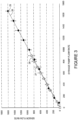
- Figure 3 illustrates the accurate operation of both the sample flow sensor 6 and sheath flow sensor 7 by comparing flow rates measured with these sensors to flow rates measured by a standard syringe pump.
- Sample fluid sensor and sheath fluid sensor used are models LG16-0150A and LG16-1000A. respectively, (Sensirion Inc., Westlake Village, CA), and the syringe pump used was model NE-1000 (New Era Pump Systems Inc., Farmingdale, NY). Closed diamonds 25 and solid line 26 show the correlation between sample flow rates measured with sample flow sensor 6 on the y-axis and the syringe pump on the x-axis, both measured in nL/min.
- the data represented by open squares 27 and dashed line 28 shows the correlation between sheath flow rates measured with sheath flow sensor 7 on the y-axis and the syringe pump on the x-axis, both measured in ⁇ L/min.
- Figure 4 illustrates the problem with the commonly made assumption that a constant applied pressure delivers a constant flow rate.
- Sample flow rate in numin shown on the left-hand y-axis corresponds to the data series represented by solid line 29
- applied pressure in psi on the right-hand y-axis corresponds to the data series represented by dotted line 30.
- Figure 4 shows that although a constant pressure is being applied to the headspace in sample reservoir 4 using sample pressure regulator 2, the measured flow rate of the sample fluid is highly variable shown by solid line 29. This change in flow rate can be caused by clogs within the system other periodic or unexpected events as described above.
- the particle concentration in solution can be calculated by determining the number of qualifying detection events that pass through the detection volume in a certain time period. Therefore, if the sample flow rate is assumed rather than measured and/or controlled over that same time period, the ultimate calculated particle concentration is affected by changes in flow rate such as those observed in Figure 4 .
- Figure 5a illustrates that applying a constant pressure with sheath pressure regulator 3 to the headspace in sheath reservoir 5 is not sufficient to deliver a constant sheath flow rate.
- the pressure applied to the headspace in sheath reservoir 5 remains constant as shown by open diamonds 31 and dashed line 32 (left-hand y-axis, measured in psi), as the volume measured in mL in the sheath reservoir is increased there is a steady increase in the flow rate measured by sheath flow sensor 7 shown by closed triangles 33 and solid line 34 (right-hand y-axis in ⁇ L/min).
- Figure 5b illustrates that flow rate measurement utilized in conjunction with a feedback loop to compensate for changes in the measured flow rate can be utilized to delivery a constant flow rate.
- Sheath flow sensor 7 was utilized to measure the sheath flow rate
- feedback loop 14 was utilized to apply changes to the headspace pressure to compensate for the measured changes in sheath flow rate.
- open diamonds 35 and dashed line 36 indicate that the applied pressure over the headspace (left-hand y-axis, measured in psi) was automatically decreased to compensate for the pressure differences that resulted from increased volume in sheath reservoir 5.
- the improvement in the flow rate delivered due to the ability of the feedback loop to provide compensation is shown by the constant measured sheath flow rate (right-hand y-axis, measured in ⁇ L/min) shown by closed triangles 37 and solid line 38.
- Figure 6 illustrates the strong correlation between sheath fluid flow rate in ⁇ L/min on the x-axis and sample fluid flow rate in nL/min on the y-axis.
- a constant pressure may be applied to the headspace over the sample fluid in sample reservoir 4 using sample pressure regulator 2
- the sample fluid flow rate also changes as illustrated by open diamonds 39 and dotted line 40 showing that sheath fluid flow rate and sample fluid flow rate are anticorrelated due to increased backpressure in the sample stream at higher sheath fluid flow rates.
- the measured sample fluid flow rate may be utilized in feedback loop 13 to change the headspace pressure in sample reservoir 4 in order to supply a sample fluid flow rate that will remain constant, regardless of the sheath fluid flow rate.
- This feedback-controlled situation is illustrated with measurements of sample flow rate represented by closed triangles 41 and solid line 42 which indicate a constant sample flow rate as the sheath fluid flow rate is varied.
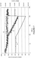
- Figure 7 shows the difference in calculated concentrations that are obtained depending on whether or not the measured sample fluid flow rate is used to correct for flow fluctuations that occurred during the time course in seconds (x-axis) of an experimental run.
- the sample pressure was set to a constant value of 1.163 ⁇ 0.006 psi.
- Solid line 43 shows that some event during the timeframe of the experiment caused an approximate 50% drop in sample flow rate (left-hand y-axis, measured in nL/min).
- the applied sample pressure is used to assume a constant sample fluid flow rate, and this constant sample fluid flow rate is in turn used to calculate the sample concentration (shown on the right-hand y-axis, measured in vpl/mL where vpl is virus-like particles)
- the calculated sample concentration over the time of the experiment shown by dotted line 44 is obtained and mimics the time profile of the sample fluid flow rate.
- solid grey line 45 illustrates the concentration measurement that is obtained if the sample fluid flow rate measured over the timeframe of the experiment is used to correct for this fluctuation in flow.
- the average particle concentration calculated for dotted line 44 is 2.1 ⁇ 10 8 vlp/ml. with a relative standard deviation of ⁇ 19% ( ⁇ 0.4 ⁇ 10 8 vlp/mL).
- the average particle concentration calculated for solid grey line 45 is 2.4 ⁇ 10 8 vlp/mL with a relative standard deviation of only ⁇ 4% ( ⁇ 0.1 ⁇ 10 8 ).
- the calculated sample concentration is more stable and relatively constant over the timeframe of the experiment with a significantly lower relative standard deviation. If the sample fluid flow rate is not controlled to be a constant, the vpl/ml result will generally be artificially high or low depending on whether the flow rate is high or low.
- This corrected concentration result is clearly an improvement over the situation where the sample fluid flow rate is not measured and/or corrected for.
- the use of a measured sample fluid flow rate to correct for flow fluctuations in calculating sample concentration was done in this case as a post-acquisition processing step. As shown by the next figure, this compensation for flow fluctuation also can be done in real time through the use of feedback loops to similarly improve particle quantification accuracy.
- Figure 8 illustrates that flow rate measurement combined with correcting for fluctuations in real-time via a feedback loop can provide an 'instantaneous' improvement in particle quantification accuracy.
- feedback loop 14 was used to control the sheath fluid flow rate by controlling the headspace pressure in sheath reservoir 5 via sheath pressure regulator 3.
- feedback loop 13 was used to control the sample fluid flow rate by controlling the headspace pressure in sample fluid reservoir 4 via sample pressure regulator 2.
- This variable applied pressure resulted in the delivery of the relatively constant sample fluid flow rate in nUmin illustrated by dotted line 47 (right-hand y-axis).
- Figure 8b illustrates the result when the measured sample fluid flow rate 47 in Figure 8a was utilized in real time to calculate the particle concentration in the sample (illustrated by solid line 48, y-axis in vpl/mL). Because the amount of fluid flowing past the excitation and detection system 9 was known, post process analysis was not necessary to qualify the results such that real time vpl may be obtained.
- the average particle concentration over the time course of this experiment is 1.6 ⁇ 10 8 vlp/mL with a relative standard deviation of ⁇ 6% ( ⁇ 0.1 ⁇ 10 8 vlp/mL). This relative standard deviation is similar to that shown in Figure 7 for the case where the concentration is calculated from the corrected sample flow rate.
- Both measuring and controlling the sample fluid flow rate in real-time through the use of a feedback loop results in particle quantification with improved accuracy compared to a situation in which an uncorrected flow rate is used to calculate particle concentration.
- correcting for sample fluid flow rate fluctuations during the run allows a concentration result to be displayed in real time, eliminating the majority of post data collection processing and decreasing overall time to result.
- using a second feedback loop to provide a constant sheath fluid flow rate has the additional advantage of stabilizing the hydrodynamic focusing effect, and further improving particle quantification.
Landscapes
- Chemical & Material Sciences (AREA)
- Dispersion Chemistry (AREA)
- Physics & Mathematics (AREA)
- Health & Medical Sciences (AREA)
- Life Sciences & Earth Sciences (AREA)
- Analytical Chemistry (AREA)
- Biochemistry (AREA)
- General Health & Medical Sciences (AREA)
- General Physics & Mathematics (AREA)
- Immunology (AREA)
- Pathology (AREA)
- Investigating Or Analysing Biological Materials (AREA)
- Investigating, Analyzing Materials By Fluorescence Or Luminescence (AREA)
Claims (15)
- Système pour déterminer le nombre de particules virales dans un volume de fluide en temps réel, comprenant :au moins une alimentation en fluide sous pression ;un réservoir à échantillon (4) contenant un fluide échantillon ayant un liquide et une pluralité de particules virales marquées par fluorescence ayant une taille inférieure à 1 micromètre, la au moins une alimentation en fluide sous pression étant en communication de fluide avec le réservoir à échantillon ;un régulateur de pression d'échantillon (2) en communication de fluide avec la au moins une alimentation en fluide sous pression et le réservoir à échantillon pour réguler la pression du réservoir à échantillon ;un réservoir de gainage (5) contenant un fluide de gainage, la au moins une alimentation en fluide sous pression étant en communication de fluide avec le réservoir de gainage ;un régulateur de pression de gainage (3) en communication de fluide avec la au moins une alimentation en fluide sous pression et le réservoir de gainage pour réguler la pression du réservoir de gainage ;une cellule d'écoulement (8), la cellule d'écoulement étant en communication de fluide avec à la fois le réservoir à échantillon et le réservoir de gainage ;un capteur d'écoulement d'échantillon (6) en communication de fluide avec le réservoir à échantillon et la cellule d'écoulement, le capteur d'écoulement d'échantillon étant couplé au régulateur de pression d'échantillon pour altérer la pression du réservoir à échantillon pour maintenir pratiquement constant, à moins de 5000 nanolitres par minute, le débit d'échantillon allant du réservoir à échantillon à la cellule d'écoulement ;un système d'excitation et de détection (9) couplé à la cellule d'écoulement pour compter, via une mesure de fluorescence, le nombre de particules virales circulant à travers la cellule d'écoulement, dans lequel le nombre total de particules virales dans le volume de fluide est indiqué en temps réel.
- Système selon la revendication 1, comprenant en outre un capteur de flux de gainage (7) en communication de fluide avec le réservoir de gainage et la cellule d'écoulement pour déterminer le débit de gainage du fluide de gainage, le capteur de gainage étant couplé au régulateur de pression de gainage pour altérer la pression du réservoir de gainage pour maintenir un débit de gainage pratiquement constant.
- Système selon la revendication 1, dans lequel le système d'excitation et de détection est couplé optiquement à la cellule d'écoulement.
- Système selon la revendication 3, dans lequel le système d'excitation et de détection comprend :une source de lumière (10), etun système de détection et d'analyse (11),dans lequel la source de lumière heurte le fluide échantillon et le système de détection et d'analyse reçoit un signal optique utilisé pour déterminer si la particule est présente.
- Système selon la revendication 4, dans lequel les virus comprennent un acide nucléique et une protéine marqués par deux espèces fluorescentes différentes capables d'être détectées de manière différenciée sur deux canaux de détection (11a, 11b), et le système de détection et d'analyse comprend deux détecteurs séparés pour détecter des signatures de fluorescence différentes des deux espèces fluorescentes différentes.
- Système selon la revendication 1, dans lequel le capteur d'écoulement d'échantillon détermine le débit de l'échantillon.
- Système selon la revendication 6, dans lequel le capteur d'écoulement d'échantillon amène le régulateur de pression d'échantillon à altérer la pression du réservoir à échantillon quand le débit de l'échantillon est en-dehors d'une plage de seuil prédéterminée.
- Système selon la revendication 1, dans lequel le capteur de flux d'échantillon est utilisé pour déterminer le taux de changement de l'écoulement d'échantillon et altère la pression du réservoir à échantillon pour maintenir un taux de changement d'écoulement d'échantillon pratiquement nul.
- Système selon la revendication 1, dans lequel le au moins un fluide sous pression est un gaz comprimé.
- Système selon l'une quelconque des revendications 1 à 9, dans lequel les particules virales ont une taille comprise entre dix et plusieurs centaines de nanomètres.
- Procédé d'utilisation d'un écoulement régulé d'un fluide échantillon pour permettre la quantification de particules virales dans le courant de fluide échantillon en temps réel, le procédé comprenant :l'obtention d'un fluide échantillon ayant un liquide et une pluralité de particules virales marquées par fluorescence ayant une taille inférieure à 1 micromètre dans un réservoir (4) en communication de fluide avec une cellule d'écoulement (8) ;la pressurisation du réservoir de fluide échantillon pour amener le fluide échantillon à s'écouler depuis le réservoir de fluide échantillon vers la cellule d'écoulement ;la mesure d'un paramètre d'écoulement du fluide échantillon s'écoulant entre le réservoir de fluide échantillon et la cellule d'écoulement ;la combinaison d'un écoulement de fluide de gainage avec le fluide échantillon avant l'entrée dans la cellule d'écoulement pour diriger l'écoulement de fluide échantillon dans la cellule d'écoulement ;la régulation de la pression du réservoir de fluide échantillon utilisant le paramètre d'écoulement mesuré pour maintenir l'écoulement de fluide échantillon à un débit pratiquement constant, inférieur à 5000 nanolitres par minute, entre le réservoir de fluide échantillon et la cellule d'écoulement ;le compte, par une mesure de fluorescence, du nombre des particules virales passant à travers la cellule d'écoulement ; etl'obtention du nombre de particules virales dans un volume de fluide en temps réel.
- Procédé selon la revendication 11, dans lequel l'étape de pressurisation du réservoir de fluide échantillon comprend le couplage d'un gaz comprimé au réservoir de fluide échantillon par l'intermédiaire d'un régulateur de pression (2).
- Procédé selon la revendication 11, comprenant en outrela disposition du fluide de gainage dans un réservoir (5) en communication de fluide avec la cellule d'écoulement ;la pressurisation du réservoir de fluide de gainage pour amener le fluide de gainage à s'écouler depuis le réservoir de fluide de gainage vers la cellule d'écoulement ;la mesure d'un paramètre d'écoulement du fluide de gainage s'écoulant entre le réservoir de fluide de gainage et la cellule d'écoulement ; etla régulation de la pression du réservoir de fluide de gainage utilisant le paramètre d'écoulement mesuré pour maintenir l'écoulement de fluide de gainage à un débit pratiquement constant.
- Procédé selon la revendication 11, dans lequel :les virus comprennent un acide nucléique et une protéine marqués par deux espèces fluorescentes différentes capables d'être détectées de manière différenciée sur deux canaux de détection (11a, 11b) ; etle comptage via une mesure de fluorescence comprend la détection de deux signatures de fluorescence différentes des deux espèces fluorescentes différentes sur deux détecteurs séparés.
- Procédé selon l'une quelconque des revendications 11 à 14, dans lequel les particules virales ont une taille comprise entre dix et plusieurs centaines de nanomètres.
Applications Claiming Priority (1)
| Application Number | Priority Date | Filing Date | Title |
|---|---|---|---|
| PCT/US2009/043811 WO2010132053A1 (fr) | 2009-05-13 | 2009-05-13 | Mesure et commande de flux pour une quantification améliorée de particules dans une cytométrie de flux |
Publications (3)
| Publication Number | Publication Date |
|---|---|
| EP2430424A1 EP2430424A1 (fr) | 2012-03-21 |
| EP2430424A4 EP2430424A4 (fr) | 2017-11-22 |
| EP2430424B1 true EP2430424B1 (fr) | 2023-04-26 |
Family
ID=43085245
Family Applications (1)
| Application Number | Title | Priority Date | Filing Date |
|---|---|---|---|
| EP09844734.5A Active EP2430424B1 (fr) | 2009-05-13 | 2009-05-13 | Mesure et commande de flux pour une quantification améliorée de particules dans une cytométrie de flux |
Country Status (4)
| Country | Link |
|---|---|
| US (2) | US10031061B2 (fr) |
| EP (1) | EP2430424B1 (fr) |
| ES (1) | ES2945686T3 (fr) |
| WO (1) | WO2010132053A1 (fr) |
Families Citing this family (30)
| Publication number | Priority date | Publication date | Assignee | Title |
|---|---|---|---|---|
| US8528427B2 (en) | 2010-10-29 | 2013-09-10 | Becton, Dickinson And Company | Dual feedback vacuum fluidics for a flow-type particle analyzer |
| EP2861957B1 (fr) * | 2012-06-14 | 2018-05-09 | Bio-rad Laboratories, Inc. | Système de distribution de gaine ajustable de manière dynamique et à débit équilibré pour réaliser une cytofluorométrie en flux |
| WO2013192401A1 (fr) | 2012-06-22 | 2013-12-27 | Bio-Rad Laboratories, Inc. | Système de mélange de liquides et de rinçage pour cytomètre à flux |
| US9372143B2 (en) | 2013-05-15 | 2016-06-21 | Captl Llc | Scanning image flow cytometer |
| CA2912925A1 (fr) | 2013-06-28 | 2014-12-31 | Virocyt, Inc. | Traitement d'un materiel biologique pour une evaluation par cytometrie en flux de particules virales |
| EP2878374B1 (fr) * | 2013-11-29 | 2021-05-12 | IMEC vzw | Procédé pour effectuer une PCR numérique |
| JP2015141115A (ja) * | 2014-01-29 | 2015-08-03 | ヤマシンフィルタ株式会社 | 測定装置、測定方法及びプログラム |
| EP3152545A2 (fr) | 2014-06-05 | 2017-04-12 | IntelliCyt Corporation | Cytomètre de flux équipé d'un ensemble système optique |
| EP3152547A4 (fr) | 2014-06-05 | 2017-05-17 | IntelliCyt Corporation | Alignement automatique d'optiques à l'intérieur d'un cytomètre de flux |
| US9903803B2 (en) | 2014-06-05 | 2018-02-27 | Intellicyt Corporation | Flow cytometer signal peak identification employing dynamic thresholding |
| US9551644B2 (en) * | 2014-07-11 | 2017-01-24 | Intellicyt | Methods and apparatus for real-time detection and clearing of a clog |
| US10900885B2 (en) | 2014-12-19 | 2021-01-26 | Captl Llc | Flow cytometry using hydrodynamically planar flow |
| CN107615065B (zh) | 2015-03-23 | 2020-07-24 | 以埃森生物科学股份有限公司的名义经营的埃森仪器股份有限公司 | 对生物材料评估腺病毒或腺相关病毒的病毒类型的非缔合的病毒尺寸颗粒 |
| US10036698B2 (en) | 2015-06-19 | 2018-07-31 | Captl Llc | Time-sequential cytometry |
| GB201609221D0 (en) | 2016-05-25 | 2016-07-06 | Oxford Nanopore Tech Ltd | Method |
| US10436697B2 (en) * | 2016-11-19 | 2019-10-08 | Cytek Biosciences, Inc. | Flow cytometery system with fluidics control system |
| JP7063683B2 (ja) * | 2018-03-30 | 2022-05-09 | シスメックス株式会社 | フローサイトメーター及び粒子検出方法 |
| WO2020028639A1 (fr) | 2018-08-01 | 2020-02-06 | Essen Instruments, Inc. D/B/A Essen Bioscience, Inc. | Procédés, kits et compositions de coloration pour l'évaluation par cytométrie de flux de particules de taille virale non associées à l'aide de multiples colorants fluorogènes |
| US11131618B2 (en) * | 2018-08-10 | 2021-09-28 | Cytek Biosciences, Inc. | Smart flow cytometers with self monitoring and self validation |
| US11137337B2 (en) | 2019-01-21 | 2021-10-05 | Essen Instruments, Inc. | Flow cytometry with data analysis for optimized dilution of fluid samples for flow cytometry investigation |
| EP3948279B1 (fr) | 2019-03-26 | 2025-06-18 | Sartorius BioAnalytical Instruments, Inc. | Évaluation par cytométrie en flux pour particules virales non enrobées non associées |
| JP7520961B2 (ja) * | 2019-10-07 | 2024-07-23 | パーティクル・メージャーリング・システムズ・インコーポレーテッド | 遠隔警報監視及び制御を有する粒子検出器 |
| US11709116B2 (en) | 2020-02-04 | 2023-07-25 | Sartorius Bioanalytical Instruments, Inc. | Liquid flourescent dye concentrate for flow cytometry evaluation of virus-size particles and related products and methods |
| EP4111176A4 (fr) * | 2020-02-26 | 2023-08-16 | Becton, Dickinson and Company | Systèmes de détection de lumière dotés d'un détecteur de diffusion de lumière secondaire et leurs procédés d'utilisation |
| EP3947970B1 (fr) * | 2020-05-19 | 2024-03-20 | Life Technologies Corporation | Système fluidique à deux étages avec pulsation réduite |
| US12203914B2 (en) | 2020-11-12 | 2025-01-21 | Sartorius Bioanalytical Instruments, Inc. | Viral clearance evaluation for biological medical product preparation processes |
| CN214895849U (zh) | 2021-01-28 | 2021-11-26 | 贝克曼库尔特生物科技(苏州)有限公司 | 气泡检测装置和样本处理仪 |
| WO2022245431A1 (fr) * | 2021-05-17 | 2022-11-24 | Becton, Dickinson And Company | Analyseurs de particules à compteurs de scintillation et procédés associés d'utilisation |
| CN115078324B (zh) * | 2022-06-30 | 2023-03-10 | 嘉兴市唯真生物科技有限公司 | 一种高通量流式荧光检测方法、智能终端及存储介质 |
| CN120214347B (zh) * | 2025-03-26 | 2026-04-21 | 青岛瑞斯凯尔生物科技股份有限公司 | 一种流式检测用样本自动分配方法 |
Citations (1)
| Publication number | Priority date | Publication date | Assignee | Title |
|---|---|---|---|---|
| US20050105077A1 (en) * | 2000-08-02 | 2005-05-19 | Aravind Padmanabhan | Miniaturized cytometer for detecting multiple species in a sample |
Family Cites Families (57)
| Publication number | Priority date | Publication date | Assignee | Title |
|---|---|---|---|---|
| US5245318A (en) * | 1987-07-24 | 1993-09-14 | Canon Kabushiki Kaisha | Particle analyzing apparatus having pressure control system |
| US5040890A (en) * | 1987-11-25 | 1991-08-20 | Becton, Dickinson And Company | Sheathed particle flow controlled by differential pressure |
| DK111990D0 (da) | 1990-05-04 | 1990-05-04 | Biometic Aps | Apparat og fremgangsmaade til analyse af en vaeskesuspension |
| JP3075367B2 (ja) | 1991-04-05 | 2000-08-14 | シスメックス株式会社 | 粒子分析方法及び装置 |
| US5395588A (en) | 1992-12-14 | 1995-03-07 | Becton Dickinson And Company | Control of flow cytometer having vacuum fluidics |
| JP3052665B2 (ja) | 1993-01-26 | 2000-06-19 | 株式会社日立製作所 | フローセル装置 |
| US5306467A (en) * | 1993-02-17 | 1994-04-26 | Hamilton-Thorn Research | Apparatus for measurement of cell concentration in a biological sample employing a magnetic slide loading apparatus |
| US5483469A (en) | 1993-08-02 | 1996-01-09 | The Regents Of The University Of California | Multiple sort flow cytometer |
| US5602039A (en) | 1994-10-14 | 1997-02-11 | The University Of Washington | Flow cytometer jet monitor system |
| DK0925494T3 (da) | 1996-09-04 | 2002-07-01 | Scandinavian Micro Biodevices | Mikrostrømningssystem til partikelseparation og analyse |
| US6183697B1 (en) | 1997-05-27 | 2001-02-06 | Sysmex Corporation | Particle measuring apparatus |
| US5895764A (en) | 1997-11-24 | 1999-04-20 | University Of New Mexico | Controlled sheath flow injection cytometry |
| US6248590B1 (en) | 1998-02-27 | 2001-06-19 | Cytomation, Inc. | Method and apparatus for flow cytometry |
| JP4215397B2 (ja) | 1998-05-14 | 2009-01-28 | ルミネックス コーポレイション | 多重分析物診断システム |
| US6110427A (en) | 1998-08-14 | 2000-08-29 | Becton, Dickinson And Company | Flow regulator to maintain controllable volumetric flow rate |
| EP1144958B1 (fr) | 1998-12-22 | 2004-03-24 | Sensirion AG | Procede et capteur pour mesurer un flux massique |
| US6256096B1 (en) | 1999-01-11 | 2001-07-03 | Softray | Flow cytometry apparatus and method |
| US6890487B1 (en) | 1999-09-30 | 2005-05-10 | Science & Technology Corporation ©UNM | Flow cytometry for high throughput screening |
| WO2001084087A1 (fr) | 2000-05-04 | 2001-11-08 | Sensirion Ag | Detecteur de debit pour fluides |
| US7978329B2 (en) | 2000-08-02 | 2011-07-12 | Honeywell International Inc. | Portable scattering and fluorescence cytometer |
| US8071051B2 (en) | 2004-05-14 | 2011-12-06 | Honeywell International Inc. | Portable sample analyzer cartridge |
| US7641856B2 (en) * | 2004-05-14 | 2010-01-05 | Honeywell International Inc. | Portable sample analyzer with removable cartridge |
| US7016022B2 (en) | 2000-08-02 | 2006-03-21 | Honeywell International Inc. | Dual use detectors for flow cytometry |
| US6597438B1 (en) | 2000-08-02 | 2003-07-22 | Honeywell International Inc. | Portable flow cytometry |
| US7420659B1 (en) * | 2000-06-02 | 2008-09-02 | Honeywell Interantional Inc. | Flow control system of a cartridge |
| US7471394B2 (en) | 2000-08-02 | 2008-12-30 | Honeywell International Inc. | Optical detection system with polarizing beamsplitter |
| US7277166B2 (en) | 2000-08-02 | 2007-10-02 | Honeywell International Inc. | Cytometer analysis cartridge optical configuration |
| US7061595B2 (en) | 2000-08-02 | 2006-06-13 | Honeywell International Inc. | Miniaturized flow controller with closed loop regulation |
| EP1466162A1 (fr) | 2002-01-10 | 2004-10-13 | Board Of Regents The University Of Texas System | Systeme de tri de flux et procedes associes |
| GB2388189B (en) | 2002-04-29 | 2006-01-11 | Robert Jeffrey Geddes Carr | Optical detection and analysis of particles |
| US6880414B2 (en) | 2002-08-08 | 2005-04-19 | Becton Dickinson And Company | Sort block and liquid collection device for sorting flow cytometer |
| US7428971B2 (en) * | 2002-11-01 | 2008-09-30 | Techno Network Shikoku Co., Ltd. | Method for sorting and recovering fine particle and apparatus for recovery |
| BRPI0408857B1 (pt) | 2003-03-28 | 2018-09-11 | Inguran Llc | aparelho, métodos e processos para separar partículas e para prover esperma de animal separado por sexo |
| KR101135138B1 (ko) | 2003-08-13 | 2012-04-16 | 루미넥스 코포레이션 | 유세포 분석기식 측정 시스템의 하나 이상의 파라미터의제어 방법 |
| US7355696B2 (en) | 2005-02-01 | 2008-04-08 | Arryx, Inc | Method and apparatus for sorting cells |
| FR2883970B1 (fr) * | 2005-03-31 | 2007-11-16 | C2 Diagnostics Sa | Dispositif hydraulique pour appareil d'analyse sanguine, procede associe et appareil d'analyse equipe d'un tel dispositif |
| US7307721B2 (en) | 2005-04-13 | 2007-12-11 | Brightwell Technologies | Particle imaging system with a varying flow rate |
| EP1875200A1 (fr) | 2005-04-29 | 2008-01-09 | Honeywell International Inc. | Procede de comptage et de mesure de la taille de cellules utilisant un cytometre |
| US20060248811A1 (en) | 2005-05-04 | 2006-11-09 | Universal Form Clamp Co., Inc. | Anchor positioning assembly |
| JP4995197B2 (ja) | 2005-07-01 | 2012-08-08 | ハネウェル・インターナショナル・インコーポレーテッド | 3d流体力学的集束を有する成形カートリッジ |
| US8303894B2 (en) | 2005-10-13 | 2012-11-06 | Accuri Cytometers, Inc. | Detection and fluidic system of a flow cytometer |
| US8017402B2 (en) | 2006-03-08 | 2011-09-13 | Accuri Cytometers, Inc. | Fluidic system for a flow cytometer |
| US7776268B2 (en) | 2005-10-13 | 2010-08-17 | Accuri Cytometers, Inc. | User interface for a fluidic system of a flow cytometer |
| US8182767B2 (en) | 2005-12-27 | 2012-05-22 | Honeywell International Inc. | Needle-septum interface for a fluidic analyzer |
| US7485153B2 (en) | 2005-12-27 | 2009-02-03 | Honeywell International Inc. | Fluid free interface for a fluidic analyzer |
| JP5431732B2 (ja) | 2005-12-29 | 2014-03-05 | ハネウェル・インターナショナル・インコーポレーテッド | マイクロ流体フォーマットにおけるアッセイ実装 |
| US8283177B2 (en) | 2006-03-08 | 2012-10-09 | Accuri Cytometers, Inc. | Fluidic system with washing capabilities for a flow cytometer |
| US7780916B2 (en) | 2006-03-08 | 2010-08-24 | Accuri Cytometers, Inc. | Flow cytometer system with unclogging feature |
| US7981661B2 (en) | 2006-04-17 | 2011-07-19 | Accuri Cytometers, Inc. | Flow cytometer system with sheath and waste fluid measurement |
| US20090105963A1 (en) | 2006-05-13 | 2009-04-23 | Jesper Laursen | Methods for Flow Cytometry Analyses of Un-Lysed Cells from Biological Fluids |
| US8715573B2 (en) | 2006-10-13 | 2014-05-06 | Accuri Cytometers, Inc. | Fluidic system for a flow cytometer with temporal processing |
| US8202733B1 (en) * | 2006-12-18 | 2012-06-19 | Shervin Javadi | System and method for obtaining a differential flow rate |
| US7817276B2 (en) | 2007-02-05 | 2010-10-19 | Palo Alto Research Center Incorporated | Distinguishing objects |
| EP2664916B1 (fr) | 2007-04-02 | 2017-02-08 | Acoustic Cytometry Systems, Inc. | Procédé de manipulation d'un fluide à l'intérieur d'une cuve à circulation à l'aide d'une focalisation acoustique |
| US7691636B2 (en) | 2007-05-23 | 2010-04-06 | Beckman Coulter, Inc. | Method and apparatus for compensating for variations in particle trajectories in electrostatic sorter for flowcell cytometer |
| US8263955B2 (en) | 2008-12-18 | 2012-09-11 | Palo Alto Research Center Incorporated | Causing relative motion |
| WO2010114858A1 (fr) | 2009-03-30 | 2010-10-07 | Trustees Of Boston University | Mélangeurs à réservoir tampon et communication de soupapes à distance pour dispositifs microfluidiques |
-
2009
- 2009-05-13 WO PCT/US2009/043811 patent/WO2010132053A1/fr not_active Ceased
- 2009-05-13 ES ES09844734T patent/ES2945686T3/es active Active
- 2009-05-13 EP EP09844734.5A patent/EP2430424B1/fr active Active
- 2009-05-13 US US13/319,662 patent/US10031061B2/en active Active
-
2018
- 2018-07-19 US US16/040,168 patent/US10705007B2/en active Active
Patent Citations (1)
| Publication number | Priority date | Publication date | Assignee | Title |
|---|---|---|---|---|
| US20050105077A1 (en) * | 2000-08-02 | 2005-05-19 | Aravind Padmanabhan | Miniaturized cytometer for detecting multiple species in a sample |
Also Published As
| Publication number | Publication date |
|---|---|
| EP2430424A4 (fr) | 2017-11-22 |
| US20190041314A1 (en) | 2019-02-07 |
| ES2945686T3 (es) | 2023-07-05 |
| EP2430424A1 (fr) | 2012-03-21 |
| WO2010132053A1 (fr) | 2010-11-18 |
| US10031061B2 (en) | 2018-07-24 |
| US10705007B2 (en) | 2020-07-07 |
| US20120070818A1 (en) | 2012-03-22 |
Similar Documents
| Publication | Publication Date | Title |
|---|---|---|
| US10705007B2 (en) | Flow measurement and control for improved quantification of particles in flow cytometry | |
| US20200150023A1 (en) | Instrument and Method for Optical Particle Sensing | |
| CN101379387B (zh) | 在一次性卡片上的差示白细胞计数 | |
| JP4621249B2 (ja) | 試料分析システム | |
| JP4621248B2 (ja) | 可搬型試料分析器カートリッジ | |
| CN102753955B (zh) | 一次性芯片型流动室与利用其的细胞分选仪 | |
| CN111257582A (zh) | 样本分析仪及其样本分析方法 | |
| US6525807B1 (en) | Particle analyzing apparatus | |
| JP6116502B2 (ja) | 検体分析装置および検体分析方法 | |
| CN113640198A (zh) | 一种单细胞计数的方法及其系统 | |
| WO2020149042A1 (fr) | Dispositif et système d'isolation de microparticules, dispositif d'isolation de gouttelettes, et dispositif et programme de commande de gouttelettes | |
| WO2017126170A1 (fr) | Dispositif de mesure de microparticules, dispositif de traitement d'informations, et procédé de traitement d'informations | |
| WO2010079586A1 (fr) | Appareil de mesures optiques et appareil d'identification et de distribution d'échantillons | |
| JP2007114026A (ja) | 粒子分析装置用標準物質。 | |
| WO2018047441A1 (fr) | Dispositif de mesure de microparticules et procédé de mesure de microparticules | |
| US20230375459A1 (en) | Particle detection device, particle detection system, and particle detection method | |
| US20210172854A1 (en) | Microparticle measuring apparatus | |
| US12517032B2 (en) | Particle analyzer and particle analysis method | |
| CN114846316B (zh) | 信息处理装置、粒子测量装置、粒子测量系统、粒子分配装置、粒子分配系统、信息处理方法、以及存储介质 | |
| US10690583B2 (en) | Microparticle measuring device and microparticle measuring method | |
| US20030073136A1 (en) | Method of and apparatus for performing flow cytometric measurements | |
| WO2024111263A1 (fr) | Dispositif d'analyse d'échantillon biologique, système d'analyse d'échantillon biologique et procédé de vérification de l'état d'un dispositif d'analyse d'échantillon biologique | |
| Fielden et al. | Microfabricated polymer sensing systems for chemical and biochemical applications: a disposable flow cytometer |
Legal Events
| Date | Code | Title | Description |
|---|---|---|---|
| PUAI | Public reference made under article 153(3) epc to a published international application that has entered the european phase |
Free format text: ORIGINAL CODE: 0009012 |
|
| 17P | Request for examination filed |
Effective date: 20111202 |
|
| AK | Designated contracting states |
Kind code of ref document: A1 Designated state(s): AT BE BG CH CY CZ DE DK EE ES FI FR GB GR HR HU IE IS IT LI LT LU LV MC MK MT NL NO PL PT RO SE SI SK TR |
|
| DAX | Request for extension of the european patent (deleted) | ||
| RAP1 | Party data changed (applicant data changed or rights of an application transferred) |
Owner name: VIROCYT, LLC |
|
| RAP1 | Party data changed (applicant data changed or rights of an application transferred) |
Owner name: VIROCYT, INC. |
|
| RAP1 | Party data changed (applicant data changed or rights of an application transferred) |
Owner name: INTELLICYT CORPORATION |
|
| RA4 | Supplementary search report drawn up and despatched (corrected) |
Effective date: 20171024 |
|
| RIC1 | Information provided on ipc code assigned before grant |
Ipc: G01N 21/31 20060101ALI20171018BHEP Ipc: G01N 15/14 20060101AFI20171018BHEP Ipc: G01N 21/63 20060101ALI20171018BHEP |
|
| RAP1 | Party data changed (applicant data changed or rights of an application transferred) |
Owner name: ESSEN INSTRUMENTS, INC. |
|
| STAA | Information on the status of an ep patent application or granted ep patent |
Free format text: STATUS: EXAMINATION IS IN PROGRESS |
|
| 17Q | First examination report despatched |
Effective date: 20210421 |
|
| RAP1 | Party data changed (applicant data changed or rights of an application transferred) |
Owner name: SARTORIUS BIOANALYTICAL INSTRUMENTS, INC |
|
| RAP3 | Party data changed (applicant data changed or rights of an application transferred) |
Owner name: SARTORIUS BIOANALYTICAL INSTRUMENTS, INC. |
|
| GRAP | Despatch of communication of intention to grant a patent |
Free format text: ORIGINAL CODE: EPIDOSNIGR1 |
|
| STAA | Information on the status of an ep patent application or granted ep patent |
Free format text: STATUS: GRANT OF PATENT IS INTENDED |
|
| INTG | Intention to grant announced |
Effective date: 20221017 |
|
| GRAJ | Information related to disapproval of communication of intention to grant by the applicant or resumption of examination proceedings by the epo deleted |
Free format text: ORIGINAL CODE: EPIDOSDIGR1 |
|
| STAA | Information on the status of an ep patent application or granted ep patent |
Free format text: STATUS: EXAMINATION IS IN PROGRESS |
|
| GRAP | Despatch of communication of intention to grant a patent |
Free format text: ORIGINAL CODE: EPIDOSNIGR1 |
|
| STAA | Information on the status of an ep patent application or granted ep patent |
Free format text: STATUS: GRANT OF PATENT IS INTENDED |
|
| INTC | Intention to grant announced (deleted) | ||
| INTG | Intention to grant announced |
Effective date: 20221214 |
|
| GRAS | Grant fee paid |
Free format text: ORIGINAL CODE: EPIDOSNIGR3 |
|
| GRAA | (expected) grant |
Free format text: ORIGINAL CODE: 0009210 |
|
| STAA | Information on the status of an ep patent application or granted ep patent |
Free format text: STATUS: THE PATENT HAS BEEN GRANTED |
|
| AK | Designated contracting states |
Kind code of ref document: B1 Designated state(s): AT BE BG CH CY CZ DE DK EE ES FI FR GB GR HR HU IE IS IT LI LT LU LV MC MK MT NL NO PL PT RO SE SI SK TR |
|
| REG | Reference to a national code |
Ref country code: GB Ref legal event code: FG4D |
|
| REG | Reference to a national code |
Ref country code: CH Ref legal event code: EP |
|
| REG | Reference to a national code |
Ref country code: DE Ref legal event code: R096 Ref document number: 602009064817 Country of ref document: DE |
|
| REG | Reference to a national code |
Ref country code: AT Ref legal event code: REF Ref document number: 1563147 Country of ref document: AT Kind code of ref document: T Effective date: 20230515 |
|
| REG | Reference to a national code |
Ref country code: IE Ref legal event code: FG4D |
|
| P01 | Opt-out of the competence of the unified patent court (upc) registered |
Effective date: 20230526 |
|
| REG | Reference to a national code |
Ref country code: ES Ref legal event code: FG2A Ref document number: 2945686 Country of ref document: ES Kind code of ref document: T3 Effective date: 20230705 |
|
| REG | Reference to a national code |
Ref country code: LT Ref legal event code: MG9D |
|
| REG | Reference to a national code |
Ref country code: NL Ref legal event code: MP Effective date: 20230426 |
|
| REG | Reference to a national code |
Ref country code: AT Ref legal event code: MK05 Ref document number: 1563147 Country of ref document: AT Kind code of ref document: T Effective date: 20230426 |
|
| PG25 | Lapsed in a contracting state [announced via postgrant information from national office to epo] |
Ref country code: NL Free format text: LAPSE BECAUSE OF FAILURE TO SUBMIT A TRANSLATION OF THE DESCRIPTION OR TO PAY THE FEE WITHIN THE PRESCRIBED TIME-LIMIT Effective date: 20230426 |
|
| PG25 | Lapsed in a contracting state [announced via postgrant information from national office to epo] |
Ref country code: SE Free format text: LAPSE BECAUSE OF FAILURE TO SUBMIT A TRANSLATION OF THE DESCRIPTION OR TO PAY THE FEE WITHIN THE PRESCRIBED TIME-LIMIT Effective date: 20230426 Ref country code: PT Free format text: LAPSE BECAUSE OF FAILURE TO SUBMIT A TRANSLATION OF THE DESCRIPTION OR TO PAY THE FEE WITHIN THE PRESCRIBED TIME-LIMIT Effective date: 20230828 Ref country code: NO Free format text: LAPSE BECAUSE OF FAILURE TO SUBMIT A TRANSLATION OF THE DESCRIPTION OR TO PAY THE FEE WITHIN THE PRESCRIBED TIME-LIMIT Effective date: 20230726 Ref country code: AT Free format text: LAPSE BECAUSE OF FAILURE TO SUBMIT A TRANSLATION OF THE DESCRIPTION OR TO PAY THE FEE WITHIN THE PRESCRIBED TIME-LIMIT Effective date: 20230426 |
|
| PG25 | Lapsed in a contracting state [announced via postgrant information from national office to epo] |
Ref country code: PL Free format text: LAPSE BECAUSE OF FAILURE TO SUBMIT A TRANSLATION OF THE DESCRIPTION OR TO PAY THE FEE WITHIN THE PRESCRIBED TIME-LIMIT Effective date: 20230426 Ref country code: LV Free format text: LAPSE BECAUSE OF FAILURE TO SUBMIT A TRANSLATION OF THE DESCRIPTION OR TO PAY THE FEE WITHIN THE PRESCRIBED TIME-LIMIT Effective date: 20230426 Ref country code: LT Free format text: LAPSE BECAUSE OF FAILURE TO SUBMIT A TRANSLATION OF THE DESCRIPTION OR TO PAY THE FEE WITHIN THE PRESCRIBED TIME-LIMIT Effective date: 20230426 Ref country code: IS Free format text: LAPSE BECAUSE OF FAILURE TO SUBMIT A TRANSLATION OF THE DESCRIPTION OR TO PAY THE FEE WITHIN THE PRESCRIBED TIME-LIMIT Effective date: 20230826 Ref country code: HR Free format text: LAPSE BECAUSE OF FAILURE TO SUBMIT A TRANSLATION OF THE DESCRIPTION OR TO PAY THE FEE WITHIN THE PRESCRIBED TIME-LIMIT Effective date: 20230426 Ref country code: GR Free format text: LAPSE BECAUSE OF FAILURE TO SUBMIT A TRANSLATION OF THE DESCRIPTION OR TO PAY THE FEE WITHIN THE PRESCRIBED TIME-LIMIT Effective date: 20230727 |
|
| PG25 | Lapsed in a contracting state [announced via postgrant information from national office to epo] |
Ref country code: FI Free format text: LAPSE BECAUSE OF FAILURE TO SUBMIT A TRANSLATION OF THE DESCRIPTION OR TO PAY THE FEE WITHIN THE PRESCRIBED TIME-LIMIT Effective date: 20230426 |
|
| PG25 | Lapsed in a contracting state [announced via postgrant information from national office to epo] |
Ref country code: SK Free format text: LAPSE BECAUSE OF FAILURE TO SUBMIT A TRANSLATION OF THE DESCRIPTION OR TO PAY THE FEE WITHIN THE PRESCRIBED TIME-LIMIT Effective date: 20230426 |
|
| PG25 | Lapsed in a contracting state [announced via postgrant information from national office to epo] |
Ref country code: MC Free format text: LAPSE BECAUSE OF FAILURE TO SUBMIT A TRANSLATION OF THE DESCRIPTION OR TO PAY THE FEE WITHIN THE PRESCRIBED TIME-LIMIT Effective date: 20230426 |
|
| REG | Reference to a national code |
Ref country code: DE Ref legal event code: R097 Ref document number: 602009064817 Country of ref document: DE |
|
| REG | Reference to a national code |
Ref country code: BE Ref legal event code: MM Effective date: 20230531 |
|
| PG25 | Lapsed in a contracting state [announced via postgrant information from national office to epo] |
Ref country code: SK Free format text: LAPSE BECAUSE OF FAILURE TO SUBMIT A TRANSLATION OF THE DESCRIPTION OR TO PAY THE FEE WITHIN THE PRESCRIBED TIME-LIMIT Effective date: 20230426 Ref country code: RO Free format text: LAPSE BECAUSE OF FAILURE TO SUBMIT A TRANSLATION OF THE DESCRIPTION OR TO PAY THE FEE WITHIN THE PRESCRIBED TIME-LIMIT Effective date: 20230426 Ref country code: MC Free format text: LAPSE BECAUSE OF FAILURE TO SUBMIT A TRANSLATION OF THE DESCRIPTION OR TO PAY THE FEE WITHIN THE PRESCRIBED TIME-LIMIT Effective date: 20230426 Ref country code: LU Free format text: LAPSE BECAUSE OF NON-PAYMENT OF DUE FEES Effective date: 20230513 Ref country code: EE Free format text: LAPSE BECAUSE OF FAILURE TO SUBMIT A TRANSLATION OF THE DESCRIPTION OR TO PAY THE FEE WITHIN THE PRESCRIBED TIME-LIMIT Effective date: 20230426 Ref country code: DK Free format text: LAPSE BECAUSE OF FAILURE TO SUBMIT A TRANSLATION OF THE DESCRIPTION OR TO PAY THE FEE WITHIN THE PRESCRIBED TIME-LIMIT Effective date: 20230426 Ref country code: CZ Free format text: LAPSE BECAUSE OF FAILURE TO SUBMIT A TRANSLATION OF THE DESCRIPTION OR TO PAY THE FEE WITHIN THE PRESCRIBED TIME-LIMIT Effective date: 20230426 |
|
| REG | Reference to a national code |
Ref country code: IE Ref legal event code: MM4A |
|
| PLBE | No opposition filed within time limit |
Free format text: ORIGINAL CODE: 0009261 |
|
| STAA | Information on the status of an ep patent application or granted ep patent |
Free format text: STATUS: NO OPPOSITION FILED WITHIN TIME LIMIT |
|
| 26N | No opposition filed |
Effective date: 20240129 |
|
| PG25 | Lapsed in a contracting state [announced via postgrant information from national office to epo] |
Ref country code: IE Free format text: LAPSE BECAUSE OF NON-PAYMENT OF DUE FEES Effective date: 20230513 |
|
| PG25 | Lapsed in a contracting state [announced via postgrant information from national office to epo] |
Ref country code: IE Free format text: LAPSE BECAUSE OF NON-PAYMENT OF DUE FEES Effective date: 20230513 |
|
| PG25 | Lapsed in a contracting state [announced via postgrant information from national office to epo] |
Ref country code: SI Free format text: LAPSE BECAUSE OF FAILURE TO SUBMIT A TRANSLATION OF THE DESCRIPTION OR TO PAY THE FEE WITHIN THE PRESCRIBED TIME-LIMIT Effective date: 20230426 |
|
| PG25 | Lapsed in a contracting state [announced via postgrant information from national office to epo] |
Ref country code: SI Free format text: LAPSE BECAUSE OF FAILURE TO SUBMIT A TRANSLATION OF THE DESCRIPTION OR TO PAY THE FEE WITHIN THE PRESCRIBED TIME-LIMIT Effective date: 20230426 Ref country code: BE Free format text: LAPSE BECAUSE OF NON-PAYMENT OF DUE FEES Effective date: 20230531 |
|
| PG25 | Lapsed in a contracting state [announced via postgrant information from national office to epo] |
Ref country code: BG Free format text: LAPSE BECAUSE OF FAILURE TO SUBMIT A TRANSLATION OF THE DESCRIPTION OR TO PAY THE FEE WITHIN THE PRESCRIBED TIME-LIMIT Effective date: 20230426 |
|
| PG25 | Lapsed in a contracting state [announced via postgrant information from national office to epo] |
Ref country code: BG Free format text: LAPSE BECAUSE OF FAILURE TO SUBMIT A TRANSLATION OF THE DESCRIPTION OR TO PAY THE FEE WITHIN THE PRESCRIBED TIME-LIMIT Effective date: 20230426 |
|
| PGFP | Annual fee paid to national office [announced via postgrant information from national office to epo] |
Ref country code: DE Payment date: 20250519 Year of fee payment: 17 |
|
| PGFP | Annual fee paid to national office [announced via postgrant information from national office to epo] |
Ref country code: GB Payment date: 20250522 Year of fee payment: 17 Ref country code: ES Payment date: 20250616 Year of fee payment: 17 |
|
| PGFP | Annual fee paid to national office [announced via postgrant information from national office to epo] |
Ref country code: IT Payment date: 20250530 Year of fee payment: 17 |
|
| PGFP | Annual fee paid to national office [announced via postgrant information from national office to epo] |
Ref country code: FR Payment date: 20250521 Year of fee payment: 17 |
|
| PGFP | Annual fee paid to national office [announced via postgrant information from national office to epo] |
Ref country code: CH Payment date: 20250601 Year of fee payment: 17 |
|
| PG25 | Lapsed in a contracting state [announced via postgrant information from national office to epo] |
Ref country code: HU Free format text: LAPSE BECAUSE OF FAILURE TO SUBMIT A TRANSLATION OF THE DESCRIPTION OR TO PAY THE FEE WITHIN THE PRESCRIBED TIME-LIMIT; INVALID AB INITIO Effective date: 20090513 |
|
| PG25 | Lapsed in a contracting state [announced via postgrant information from national office to epo] |
Ref country code: CY Free format text: LAPSE BECAUSE OF FAILURE TO SUBMIT A TRANSLATION OF THE DESCRIPTION OR TO PAY THE FEE WITHIN THE PRESCRIBED TIME-LIMIT; INVALID AB INITIO Effective date: 20090513 |
|
| PG25 | Lapsed in a contracting state [announced via postgrant information from national office to epo] |
Ref country code: TR Free format text: LAPSE BECAUSE OF FAILURE TO SUBMIT A TRANSLATION OF THE DESCRIPTION OR TO PAY THE FEE WITHIN THE PRESCRIBED TIME-LIMIT Effective date: 20230426 |