EP2430470B1 - Distribution et traitement vidéo numérique des données d'un récepteur radar haute fidélité - Google Patents
Distribution et traitement vidéo numérique des données d'un récepteur radar haute fidélité Download PDFInfo
- Publication number
- EP2430470B1 EP2430470B1 EP09779454.9A EP09779454A EP2430470B1 EP 2430470 B1 EP2430470 B1 EP 2430470B1 EP 09779454 A EP09779454 A EP 09779454A EP 2430470 B1 EP2430470 B1 EP 2430470B1
- Authority
- EP
- European Patent Office
- Prior art keywords
- azimuth
- radar data
- digital
- data
- antenna
- Prior art date
- Legal status (The legal status is an assumption and is not a legal conclusion. Google has not performed a legal analysis and makes no representation as to the accuracy of the status listed.)
- Active
Links
Images


Classifications
-
- G—PHYSICS
- G01—MEASURING; TESTING
- G01S—RADIO DIRECTION-FINDING; RADIO NAVIGATION; DETERMINING DISTANCE OR VELOCITY BY USE OF RADIO WAVES; LOCATING OR PRESENCE-DETECTING BY USE OF THE REFLECTION OR RERADIATION OF RADIO WAVES; ANALOGOUS ARRANGEMENTS USING OTHER WAVES
- G01S7/00—Details of systems according to groups G01S13/00, G01S15/00, G01S17/00
- G01S7/003—Transmission of data between radar, sonar or lidar systems and remote stations
-
- G—PHYSICS
- G01—MEASURING; TESTING
- G01S—RADIO DIRECTION-FINDING; RADIO NAVIGATION; DETERMINING DISTANCE OR VELOCITY BY USE OF RADIO WAVES; LOCATING OR PRESENCE-DETECTING BY USE OF THE REFLECTION OR RERADIATION OF RADIO WAVES; ANALOGOUS ARRANGEMENTS USING OTHER WAVES
- G01S13/00—Systems using the reflection or reradiation of radio waves, e.g. radar systems; Analogous systems using reflection or reradiation of waves whose nature or wavelength is irrelevant or unspecified
- G01S13/003—Bistatic radar systems; Multistatic radar systems
-
- G—PHYSICS
- G01—MEASURING; TESTING
- G01S—RADIO DIRECTION-FINDING; RADIO NAVIGATION; DETERMINING DISTANCE OR VELOCITY BY USE OF RADIO WAVES; LOCATING OR PRESENCE-DETECTING BY USE OF THE REFLECTION OR RERADIATION OF RADIO WAVES; ANALOGOUS ARRANGEMENTS USING OTHER WAVES
- G01S7/00—Details of systems according to groups G01S13/00, G01S15/00, G01S17/00
- G01S7/02—Details of systems according to groups G01S13/00, G01S15/00, G01S17/00 of systems according to group G01S13/00
- G01S7/28—Details of pulse systems
- G01S7/285—Receivers
- G01S7/295—Means for transforming co-ordinates or for evaluating data, e.g. using computers
- G01S7/298—Scan converters
Definitions
- This disclosure generally relates to radar systems and radar signal processing and more particularly to a system and method for full fidelity radar receiver digital video distribution and processing.
- Radar is a system that uses electromagnetic waves to identify the range, altitude, direction, or speed of both moving and fixed objects, such as aircraft, ships, and terrain.
- a radar system has a transmitter that emits either microwave or radio wave signals that are reflected by the target and detected by a receiver.
- Radar signals may be distributed to a variety of radar displays. Radar signal distribution has been implemented with a central analog radar switchboard that accepts analog signals from multiple radars and provides outputs to a number of dedicated radar display consoles.
- the analog signals are transported from the radar receiver to the base of a ship for digitization. Such an arrangement requires the use of several analog cables throughout the ship and the use of specialized electronics within each display console to digitize the information.
- US 5,923,285 A discloses a system for the distribution of digitized radar video over a digital network.
- the digital network is located at the low data rate point in the radar scan conversion process resulting in low network bandwidth with no loss of video fidelity.
- the conversion from analog to digital distribution allows for a totally integrated information network eliminating the need for a dedicated radar distribution network. This approach broadens the use of radar data from traditionally dedicated consoles to all network users.
- the radar and display system architecture consists of one or more radars and displays. Each radar has a video digitizer and azimuth decoder that is coupled to receive radar analog signals representative of radar data in polar coordinates or other format, which are constructed to provide digital signals representative of said analog signals.
- Azimuth and range compressors are coupled to receive the decoded digital signals, which are constructed to provide range and azimuth data compression to the decoded digital signals.
- a window detector is coupled to receive the output of the compressors and is constructed to provide a window-detected output signal to conform to the display screen.
- the video signals are transferred to the display systems over a digital network, which is inserted between the output of the window detectors and the display systems.
- Each display system contains a video display configured for Cartesian coordinate display data and a scan converter, which converts digital data from the window detectors of selected radar processors from polar coordinate data format into Cartesian coordinate data format.
- WO 2006/110973 discloses distribution of raw full fidelity radar data over a network.
- EP 1 712 931 and US 2004/056791 both disclose a radar system embedded in the pedestal of the antenna.
- a radar distribution system may be desired that allows for the distribution of full fidelity digital radar video to multiple display consoles, obviating the need for specialized electronics within each display console while preserving the benefits of accessing unprocessed, full fidelity radar video.
- a processing device for providing radar data onto a local area network comprising:
- a system for providing radar data onto a local area network comprising a plurality of antennas, each antenna including the processing device according to the first aspect, a plurality of computer and display units operable to process and display digital radar data generated by the processing devices; and a local area network coupling the processing devices and the computer and display units.
- a method for providing radar data onto a local area network comprising:
- a processing device for providing radar data onto a local area network includes an analog-to-digital converter operable to receive analog radar data from an antenna and converter operable to convert the analog radar data into digital radar data.
- An interference rejector removes radar signals of other antennas from the digital radar data.
- a range bin decimator limits the digital radar data to a threshold number of range bins.
- a trigger-to-azimuth converter associates the digital radar data to particular azimuths of rotation of the antenna.
- a local area network manager places the digital radar data onto a local area network.
- the processing device may be located in the pedestal with the antenna.
- a plurality of processing devices associated with a plurality of antennas may provide digital radar data onto the local area network.
- a plurality of computers may be connected to the local area network and each computer can process the digital radar data from one or more processing devices to present a radar image on a display.
- a potential technical advantage of some embodiments of the invention is the ability to minimize the cost of installing multiple navigation radars and displays aboard a ship.
- Another potential technical advantage of some embodiments of the invention is the ability to provide full fidelity digital video to each radar display console to allow each display console full capability for sensing and tuning the radar signal.
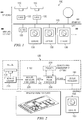
- FIGURE 1 shows the environment within which one embodiment of a radar system for full fidelity radar receiver digital video distribution and processing may operate.
- radar system 100 includes antennas 110 that propagate electromagnetic signals that are later received by transceivers. Each transceiver passes the received analog signals to a radar scan converter 120, which digitizes and processes the signals for distribution to multiple Commercial Off-The-Shelf (COTS) computers and monitors 130 over a digital network 140.
- COTS Commercial Off-The-Shelf
- the radar scan converter performs minimal pre-processing such that each COTS computer and monitor receives full fidelity digital radar video.
- Antennas 110 send out pulses of microwave or radio wave signals that are reflected by an object and detected by a transceiver.
- the distance from the object to the transceiver is related to the time it takes for the reflected waves to return to the transceiver.
- Antennas may be designed to emit signals at a variety of timing intervals, with the pattern of pulses known as pulse repetition frequency (PRF).
- PRF pulse repetition frequency
- PRF pulse repetition frequency
- Antennas 110 may be used as part of a radar, phased array, or similar apparatus.
- an antenna scans the 360 degree rotation at a rate no less than 12 revolutions per minute (RPM).
- RPM revolutions per minute
- ARPA Automatic Radar Plotting Aid
- HSC High Speed Craft
- Many military surface search radar antennas use scan rates up to 60 RPM. Thus, different scan rates will need to be taken into account.
- Radar system 100 may support a set of range scales in a geometric series that doubles (or halves) with each increment (decrement). Typical range scales are 1.5, 3, 6, 12, 24, and 48 nautical miles, with the set of range scales extensible on both ends. On a display, the physical size of the radar image (PPI) stays fixed with the distance represented by each pixel changing with the range scale.
- PPI radar image
- the radar scan converter 120 allows for the signal processing to be migrated to the COTS computers and displays 130 by providing radar signals received by an antenna onto the digital network 140. Radar scan converter 120 provides high bandwidth information or imagery over a broadcast network for simultaneous use by a large number of COTS computers and displays 130.
- Digital network 140 represents any suitable combination and arrangement of components supporting communications between radar scan converters 120 and COTS computers and displays 130.
- digital network 140 may be an Ethernet within a local area network (LAN) or components in other suitable communications networks.
- LAN local area network
- the digital signal is generated using a 20 MHz ADC with 12 bits. This is determined from the shortest pulse width of IMO radar antennas being between 50 and 100 nanoseconds.
- the PRF corresponding to the shortest pulse widths is usually around 3 kHz providing an unambiguous range of about 27 nautical miles or 6662 ADC samples (range bins) every 0.333 milliseconds.
- the electronics are calibrated to use some of the lower ADC bits for receiver noise. For example, 3 bits may be used for the mean noise so that the 5 sigma noise level is around ADC level 48 (more than 5 bits). To prevent saturation by sea clutter, and loss of short range target detection, more than 8 bits in each ADC sample are needed. While 10 or 11 bits may suffice, the standard is 12 bits. If the 5 sigma noise level is attenuated below 4 bits, then the noise and long rang small targets will be undetectable.
- the network usage for a single antenna/display system is multiplied by the number of antennas and the number of displays.
- Each COTS computer and display 130 may be able to access signals from a several radar scan converters 120.
- COTS computer and display 130a may be able to access the signal from radar scan converter 120a for a certain period of time, and it may be able to access the signal from radar scan converter 120b for a certain other period of time.
- COTS computers and displays 130 may not need specialized electronics to process the signals received from the radar scan converters 120.
- COTS computers and displays 130 may be able to receive unprocessed radar video such that each COTS computer and display 130 can process the radar signal at any range scale, target sensitivity, and false alarm rate as desired.
- Each COTS computer and display 130 may only require software to render the radar video on display and to accept and transmit operator controls to the transceiver.
- one COTS computer and display 130 may be the sole controller of the radar. In such an embodiment, one COTS computer and display 130 may be able to activate the radar and change pulse width modes. However, other COTS computers and displays 130 may still be able to process the data at any range scale desired.
- Each COTS computer and display 130 is contemplated to support IMO standards for range and azimuth resolution.
- a sufficient number of pixels are needed in the PPI display area to support this standard.
- Typical super video graphics array (SVGA) graphics can support a PPI display area of 1024x1024 pixels, which an satisfy the IMO standard.
- a range of video intensity colors or Shades of Green (SOG) also enhances the ability to resolve targets on the display.
- Common color schemes use 8 or 16 SOG (3 bits or 4 bits per pixel).
- FIGURE 2 illustrates a diagram showing an embodiment of a data flow and major processing blocks for a particular antenna 110 in a radar system 100 for full fidelity radar receiver digital video distribution and processing.
- Radar signals received by antenna 110 are processed by a transceiver 210 that provides analog signals to radar scan converter 120.
- Radar scan converter 120 includes an analog to LAN processor 220, a digital pulse processor 230, a display processor 240, and a tracker processor 250.
- Analog to LAN processor 220 performs analog to LAN processing and outputs digital signals onto digital network 140.
- Digital pulse processor 230 performs clutter reduction processing, combines data from multiple antennas, and formats the radar video into color codes.
- Display processor 240 provides the presentation capabilities for displaying radar data on COTS computer and display 130.
- radar scan converter 120 provides the abstraction between antenna 110 and COTS computer and display 130. Abstraction is accomplished by having a modular analog pre-processor that adapts the transceiver 210 for antenna 110 to the digital pulse processor 220.
- a tracker processor 250 provides for tracking of detected targets.
- Analog to LAN processor 220 is coupled to receive analog signals from transceiver 210 and formats radar transceiver information into digital streams of data for distribution to a variety of COTS computers and monitors. Each analog to LAN processor 220 outputs digitized signals after minimal processing. Analog to LAN processor 220 may use a modular circuit board to adapt the radar transceiver output for the digital processing needed to format the signal for coordinate conversion. Analog to LAN processor 220 outputs a continual stream of digital vectors associated with each digital azimuth.
- each analog to LAN processor 220 may be hosted on a digital board that hosts a Field Programmable Gate Array (FPGA).
- the FPGA may perform digital processing in very high speed integrated circuits (VHSIC) Hardware Description Language (VHDL).
- VHSIC very high speed integrated circuits
- VHDL Hardware Description Language
- the inputs for each analog to LAN processor 220 may be maritime radar transceiver analog signals, such as video, trigger, and azimuth.
- Azimuth is a representation of the antenna position and indicates the direction of the radar pulse.
- Trigger indicates the time at which the radar pulse is fired, and the amplitude of the radar video represents a measure of the radar echo return signal.
- the output of each radar scan converter 120 is digital radar video.
- Each analog to LAN processor 220 is contemplated to be a FPGA included in the pedestal of a Transmit/Receiver Up-Mast (TR-Up) radar of a corresponding antenna and may be installed with just two cables - one for power and one for the digital network 140.
- TR-Up Transmit/Receiver Up-Mast
- a control interface serial line for control signaling may also be used though such signaling may be incorporated into the digital network 140.
- the functions of Digital Pulse Processor 230 and Display Processor 240 are contemplated to be performed at COTS computer and display 130, but could also be implemented in a FPGA elsewhere within radar system 100.
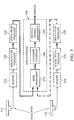
- FIGURE 3 shows an embodiment of transceiver 210 and analog to LAN processor 220 that may format radar transceiver information into digital streams of data that can be processed by a COTS computer and display 130.
- Transceiver 210 includes a RF channel selector and RF amplifier 310, a down converter and bandwidth filter 320, and a log-amp detector 330.
- Analog to LAN processor 220 may include a gain amplifier and DC bias controller 340, an analog-to-digital converter (ADC) 350, an interference rejector 360, a range bin decimator 370, a trigger-to-azimuth converter 380, and a LAN interface manager 390.
- ADC analog-to-digital converter
- transceiver 210 From each pulse emitted by the transceiver 210 at antenna 110, transceiver 210 receives echoes that are converted to a radar video signal.
- the radar video signal is a rapidly fluctuating voltage whose larger voltage peaks represent targets or clutter of some form.
- Each pulse of the transceiver 210 is associated with a direction by the antenna's azimuth (or bearing) measurement devices.
- the rate of pulses. or pulse repetition intervals (PRI triggers) is asynchronous with antenna motion, resulting in an arbitrary relationship between a number of PRI triggers per azimuth step by the antenna.
- the pulse repetition frequency (PRF) may vary from 3 KHz to 750 Hz for long range surveillance.
- Inputs provided to analog to LAN processor 220 from transceiver 210 may include composite trigger, antenna azimuth, and log-amp signals. A set of start/stop azimuths in which sector blanking is set may be included as well. Control, gain, and bias signals may also by provided. Analog to LAN processor 220 will generate a PRI estimate upon receiving triggers. Upon receiving azimuth data, analog to LAN processor 220 will estimate the antenna turn rate. Processing decisions will be made based on these measured parameters. If these parameters are under operator control, messages can be generated based on significant differences between measured and commanded values.
- Gain amplifier and bias controller 340 may prepare the radar transceiver signals to fit within the range of the ADC 350.
- the gain and bias settings may depend on the mode of the radar transceiver 210 or the settings may be constant for a particular radar transceiver 210 yet be variable depending on the type of radar transceiver.
- signals are prepared to fit within a 12-bit ADC 350 running at 40 MHz.
- Gain and bias control prior to analog to digital conversion is important to small target detection. Gain and bias set so low that receiver noise fluctuations can be seen in an ADC output will miss detection of small targets. In order to provide small target detection, gain and bias should be set so that the minimum noise level is output at approximately ADC level 8.
- ADC 350 receives the analog signals from gain amplifier and bias control 340 and converts the analog signals to digital signals. With each trigger at the antenna, the ADC may be given a fresh buffer in which to output as many as 64,000 samples. The output to the subsequent functions of the radar scan converter is an azimuth list indexed by range bins. With each rotation of the antenna, ADC 350 may produce a 2-dimensional array of 12-bit integers indexed by range and azimuth. In some embodiments, ADC 350 may operate at 40 MHz, which may allow for full fidelity radar signals to a single COTS computer and display to fit into the bandwidth provided by a standard gigabit Ethernet.
- Interference rejector 360 filters unwanted signals, such as those from another radar antenna. As the time between the pulses of a radar antenna may vary, large pulses from another radar antenna may show up as large outliers in the digital bins of the ADC 350. Interference rejection 360 filters the signals on a pulse-by-pulse basis. Three prior PRIs of digital range bins are buffered to process with the currently arriving PRI. A selectable threshold is used to determine if a middle return is an outlier. If the threshold is exceeded, the outlier return is replaced by a median of its neighbors. If the threshold is not exceeded, no replacement is performed.
- Range bin decimator 370 receives the signals from interference rejection 360 and reduces the amount of data to be processed. Range bin decimator 370 may be used to limit the data processed to 8,000 range bins per azimuth. Radars have multiple pulse width modes at which they send out pulses of wave signals, and the range extent of each range bin is a function of the pulse width mode in use. If a long pulse width mode is in use, the range bin decimator 370 may collapse a group of range bins into one large range bin such that only 8,000 range bins per azimuth are processed. If the PRF is less than 1600 Hz, another down-sampling is performed using a maximum of adjacent pairs of range bins.
- the trigger-to-azimuth converter 380 receives the signals from range bin decimator 370 and reconfigures the return pulse data into azimuth bins due to the fact that there is not necessarily a relationship between antenna pulse triggers and the antenna azimuth steps.
- the radar may produce redundant data at high pulse range frequencies.
- multiple azimuth steps may occur between triggers.
- the trigger-to-azimuth converter 380 may be used to replicate data for radar antennas operating at low pulse range frequencies and perform data reduction for radar antennas operating at high pulse range frequencies. Added complications come from blanking sectors where the antenna still rotates but pulse triggers may not be generated by transceiver 210. During a blanking sector, the output range/azimuth buffer is filled even when no triggers are received. Zero value amplitudes are placed into the buffer during a blanking sector.
- the prior azimuth of data is propagated to the next processing stage, associated with the prior azimuth, and the current PRI of range bins is stored for the new azimuth. If the change in azimuth is m times the selected azimuth increment, the prior azimuth of data is written out m times artificially incremented by one azimuth step associated with each copy of the output. If a subsequent PRI trigger is associated with a same azimuth as stored data of a previous PRI trigger, then an averaging is performed. This approach emphasizes the last PRI trigger received, but does not have to anticipate how many PRI triggers at any given azimuth will be received.
- Radar Relative Azimuth is a 12-bit word ranging in value from 0 to 4096 indicating the antenna position relative to the Bearing Change Pulse or Heading Flash or Ship's Bow.
- Range Samples are 12-bit unsigned integers indicating an array of ADC samples of radar video from each azimuth step. Status is a descriptor indicating valid data and a heartbeat.
- Range Bin Size is an unsigned integer with value between 3.75 and 60 meters indicating a range step per ADC sample.
- N is an unsigned integer ranging from 100 to 8000 indicating a number of range bins per PRI.
- Azimuth mode is a 2-bit descriptor indicating 12-bit, 11-bit, or 10-bit azimuths.
- Average PRI is an unsigned integer ranging in value from 20 to 200 indicating a low pass filtered time between triggers.
- AZ Rate is an 8-bit unsigned integer indicating a low pass filtered time between azimuth steps.
- FIGURE 4 shows an embodiment of digital pulse processor 230 that may format radar transceiver information that can be processed by a COTS computer and display 130.
- Digital pulse processor 230 performs clutter reduction processing such as Sensitivity Time Control (STC), combines video from multiple antennas, and formats the radar data into color codes.
- Digital pulse processor 230 includes a sensor data manager 410, a sensitivity time controller 420, a fast time constant (FTC) processor 430, a scan-to-scan correlator 440, a constant false alarm rate (CFAR) data extractor 450, and a color threshold and data compressor 460.
- STC Sensitivity Time Control
- FTC fast time constant
- CFAR constant false alarm rate
- Sensor data manager 410 receives the outputs generated form each analog to LAN processor 220. Other inputs received by sensor data manager 410 include ship speed and heading, pulse width mode, and STC and FTC control. Allowances in processing may be made for lost UDP/IP packets. Lost azimuth packets can be filled in using trigger to azimuth conversion performed in analog to LAN processor 220. When analog to LAN processor 220 provides an indication that the data is not valid, digital pulse processor 230 can continue to process the data but will provide a warning to the display processor 240 that the data is not proper for normal operation. Sensor data manager 410 also combines data from multiple antennas by writing azimuth data from an appropriate antenna into the appropriate locations of a polar data buffer.
- sensor data manager 410 For antennas that are not right on top of each other, sensor data manager 410 performs range/azimuth adjustments such that the data in the polar data buffer is consistent to a common reference. Different priorities can be assigned to different antennas in determining what data is placed into the polar data buffer. Data from a second antenna may be used by sensor data manager 510 to overwrite data from a first antenna if the second antenna has the latest update from a particular sector. Sensor data manager 510 can also provide azimuth encoding, range bin size/number, amplitude encoding, and clutter filtering adjustments when antennas are considerably different in their data formats.
- Sensitivity time controller 420 performs STC processing based on operator control indicating sea state, a clutter model associated with the sea state, and attenuator hardware.
- the data can be analyzed to provide automatic STC adjustments while the display is provided with clutter filtered images.
- the problem with automatic STC adjustment is in the detection of rain or land clutter that corrupts the estimated sea clutter profile. Large deviations from a best fit can alert an operator to resort back to manual STC.
- Two types of STC that can be performed include multiplicative STC and subtractive STC. Multiplicative STC reduces near range clutter fluctuations while also reducing mean clutter level. Subtractive STC eliminates mean clutter bias but does not reduce clutter fluctuations. However, in the digital domain, subtractive STC is less processor intensive.
- FTC processor 430 performs a subtraction of a sliding window mean signal estimator.
- the sampling index need not increment by 1 range bin at a time in order to get independent samples in the estimator but requires knowledge of the ratio of the transmitted pulse width to the range bin size to do so.
- Signal samples for FTC processing can be started in front of the range bin being modified. At some range, it will be desirable to switch around so that the front of rising coastlines is not suppressed by FTC. By performing FTC processing after STC processing, incorrect settings in STC processing can be compensated.
- FTC processing is performed before scan-to-scan correlation as non-linear effects in scan-to-scan correlation may make FTC processing less effective in bringing targets out of residual clutter originally left so high as to correlate over many scans.
- scan-to-scan correlation is the most significant contributor to sea clutter reduction.
- scan-to-scan correlation occurs after coordinate conversion.
- a scan-to-scan correlator 440 is positioned before coordinate conversion (in display processor 240) when the data is in a polar format.
- ship motion must be accounted for as the signals are not yet stabilized.
- Ship motion is based on constant velocity which makes for linear processing in Cartesian coordinates but non-linear processing in polar coordinates.
- Adjustments needed to combine polar-formatted data from separated locations can be calculated exactly and can also be approximated by simple formulas.
- scan-to-scan correlation is not performed beyond the horizon of the antenna.
- scan-to-scan correlation is not performed beyond the smaller of the range to the physical horizon and the range at which sea clutter return falls below the noise level A threshold can be set so that very high new video returns are not diminished by the correlation process.
- Color thresholding and data compressor 450 provides a transfer function from ADC levels to color levels. Color thresholding determines the Shade of Green to be used on the display.
- a look-up table is used for converting ADC levels to pixel colors and a simple table look up is performed for each range bin at every azimuth. The look-up table is established by dropping bits from the bottom of the signal representing mean noise and determining the minimum non-black color form the operator's gain setting (thought of as greater than mean noise).
- the operator gain setting determines the minimum ADC level to get a non-black color. The operator gain setting is then mapped linearly between minimum and maximum values.
- CFAR data extractor 450 performs data extraction for the Tracker before any loss of signal fidelity due to signal thresholding for color. Data extraction results in, for each azimuth, a list of pairs of 16-bit integers for each contiguous detection. Each pair represents the range bin index of the start of a contact's threshold crossing and the number of contiguous range bins above the threshold. The maximum number of such pairs per azimuth can be configured to preserve processing power.
- a constant false alarm rate technique for threshold generation can be used in CFAR data extractor 450. Input of graphical zones is permitted in which the threshold can be arbitrarily modified higher or lower. A slight rise in the data extraction threshold is justified near the range where mean sea clutter becomes lower than noise because sea clutter fluctuations are spikier than noise fluctuations.
- CFAR data extractor 450 provides the pairs of numbers to tracker processor 250.
- Tracker processor 250 processes the number pairs in groupings of consecutive azimuths and overlapping ranges of detections that allow some false alarm reductions when the processed groupings are too small or too large. Centroiding is performed on the number pairs and the centroids are converted to tracker coordinates and correlated to a track filter update. Real targets will correlate over 10 azimuths or more. For example, 100 detections per azimuth leads to as many as 100 contacts per beam or 36,000 centroids to process per scan. To control the amount of data for correlation and preserve detection processing power, the maximum tracking range for collision avoidance and minimum tracker range for coastal surveillance are restricted. Such control can be accomplished by setting the minimum/maximum range bin index for processing or by artificially raising the threshold to the maximum allowed value over the ranges of no interest.
- Digital pulse processor 230 outputs a status word indicating a data valid status and the azimuth reference of the output, an azimuth step code indicates whether azimuth processing is 12-bits, 11-bits, or 10-bits, a range bin size indicates a range size between 3.5 and 60 meters per sample, a two-dimensional array of colors indexed by range bin and true/relative azimuth, and data extraction pairs indicating range start and run length of video exceeding CFAR thresholds. Other than the extraction pairs, these outputs are provided to display processor 240.
- FIGURE 5 shows an embodiment of display processor 240 that presents processed radar transceiver information at a COTS computer and display 130.
- Display processor 240 accounts for presentation capabilities such as offset PPI, true/relative motion, persistence or afterglow, and combination of video from antennas installed far apart.
- Fixed offset in the PPI can be accomplished in coordinate conversion by specifying a PPI center point other than the pixel corresponding to the monitor center point, assuming that the number of pixels in coordinate conversion is sufficient to extend the PPI farther in one direction than in its reciprocal direction.
- a large PPI offset is a useful capability for judging the alignment of the radar installation.
- Persistence is achieved by selecting a color scheme for each time of day for the afterglow. Each PPI update causes a low pass filter to operate on the color.
- the time constant of the low pass filter determines the amount of time the afterglow persists on the display. Time constraints up to infinity are useful so that a bright return stays on the PPI until manual control resets the whole display. Virtually undetectable targets can be observed on the PPI with infinite persistence by a tell-tale wake in the clutter. Fast moving targets can leave a straight line wake on the display even though they move too fast for tracker correlation.
- Display processor 240 includes a mode manager 510, a coordinate converter 520, and a buffer and drawing manager 530.
- Display processor 240 receives inputs provided by digital pulse processor 230 as well as a display range scale indicating a distance represented by a pixel and a display mode indicating orientations such as north-up, head-up, course-up, persistence, and color scheme.
- Mode manager 510 knows the display mode settings for each antenna input from any number of digital pulse processors 230. From the known latitude and longitude of each antenna at the time of image processing, mode manager 510 determines the pixel location of multiple antennas' imagery relative to either the corresponding Electronic Chart Display and Information System (ECDIS) or the common reference point of the display relative to the ship's central reference point (CRP). Mode manager 510 processes offsets of antenna inputs from ship reference points. Mode manager 510 determines pixel offsets from ship speed and course based on a time difference since the last monitor update. Mode manager 510 can convert the range bin color amplitudes into primary scan colors and persistence or afterglow colors. Mode manager 510 provides antenna masks to combine multiple images from a number of antennas into a single image with desired priority for display.
- ECDIS Electronic Chart Display and Information System
- CPP central reference point
- Mode manager 510 processes offsets of antenna inputs from ship reference points.
- Mode manager 510 determines pixel offsets from ship speed and course based on a time
- Coordinate converter 520 processes two types of azimuths - relative if scan-to-scan correlation is not performed and true if can-to-scan correlation is performed. Adjustments are made for the stabilization mode requested by the display. Coordinate converter 520 converts natural radar coordinates of range and azimuth (i.e. polar coordinates) into Cartesian coordinates of the display pixels. Coordinate converter 520 takes the two-dimensional array of colors indexed by range bin and azimuth and assigns each color to a corresponding pixel row and column. Coordinate converter 520 generates a time-tagged array of pixel intensities with a status that indicates the range scale, orientation, and geodetic coordinates of the PPI center associated with antenna position. This array is indexed in relative pixel coordinates so that location on the display will depend on the addition of the pixel coordinates of some reference point such as center or upper left-hand corner.
- the buffer and drawer manager 530 is responsible for painting the PPI on the display monitor. Buffer and drawer manager 530 generates the impression of a smooth PPI sweep rotation on the display for a single antenna system at the rate of antenna rotation. Buffer and drawer manager 530 provides the persistence or afterglow for the display using a low pass filter acting on the pixel coordinates of the images as well as by adjusting color selection for the trail to provide a contrast from the last scan. For combining data from antennas that are geographically separated by many miles, buffer and drawer manager 530 uses a pixel mask to determine which antenna's data will write on each pixel.
- Any suitable logic comprising software, hardware, other logic, or any suitable combination of the preceding may perform the functions of radar system 100 and the elements within radar system 100.
- the logic may be embodied on a circuit board or on a computer readable medium and may operate on one or more computers.
- specific numbers and parameters are provided, such specificity is purely for example purposes as those skilled in the art would readily recognize that other values could be used in the implementation of radar system 100.
Landscapes
- Engineering & Computer Science (AREA)
- Radar, Positioning & Navigation (AREA)
- Remote Sensing (AREA)
- Computer Networks & Wireless Communication (AREA)
- Physics & Mathematics (AREA)
- General Physics & Mathematics (AREA)
- Radar Systems Or Details Thereof (AREA)
Claims (15)
- Dispositif de traitement (220) destiné à fournir des données radar sur un réseau local (14), comprenant :un convertisseur analogique-numérique (350) exploitable de manière à recevoir des données radar analogiques en provenance d'une antenne (110) en réponse à une impulsion générée, le convertisseur analogique-numérique (350) étant exploitable de manière à convertir les données radar analogiques en données radar numériques ;un circuit réjecteur d'interférences (360) exploitable de manière à retirer des signaux radar d'autres antennes (110) des données radar numériques ;un décimateur de cellules de distance (370) exploitable de manière à limiter les données radar numériques à un nombre seuil de cellules de distance ;un convertisseur de déclenchement en azimut (380) exploitable de manière à associer les données radar numériques à des azimuts particuliers de rotation de l'antenne (110) ; etun gestionnaire de réseau local (390) exploitable de manière à recevoir des données radar numériques traitées en provenance du convertisseur de déclenchement en azimut (380) et à placer les données radar numériques traitées sur un réseau local (140) ;caractérisé en ce que
le dispositif de traitement (220) est fourni de manière à être positionné dans un piédestal de l'antenne (110) ; et
le convertisseur de déclenchement en azimut (380) est exploitable de manière à détecter un changement d'azimut de l'antenne (110) dans lequel, à chaque fois qu'un changement d'azimut est détecté dans lequel un intervalle de répétition d'impulsions de cellules de distance est arrivé marqué par un nouvel azimut, un azimut antérieur de données est propagé vers un étage de traitement suivant, associée à l'azimut antérieur, et l'intervalle de répétition d'impulsions courant de cellules de distance est stocké pour le nouvel azimut, et, si le changement d'azimut correspond à « m » fois un incrément d'azimut sélectionné, l'azimut antérieur de données est écrit « m » fois, artificiellement incrémenté d'un pas d'azimut associé à chaque copie de la sortie, et, si un déclencheur d'intervalle de répétition d'impulsions subséquent est associé à un même azimut que des données stockées d'un déclencheur d'intervalle de répétition d'impulsions précédent, un calcul de moyenne des données radar numériques pour chaque impulsion associée à un azimut particulier est mis en oeuvre. - Dispositif de traitement selon la revendication 1, comprenant en outre :
un amplificateur de gain et contrôleur de polarisation (340) exploitable de manière à régler un gain et une polarisation afin de permettre que des fluctuations de bruit soient vues dans les données radar numériques pour des détections de petites cibles. - Dispositif de traitement selon l'une quelconque des revendications précédentes, dans lequel le décimateur de cellules de distance (370) est exploitable de manière à mettre en oeuvre un sous-échantillonnage afin de réduire davantage un nombre de cellules de distance.
- Dispositif de traitement selon la revendication 3, dans lequel le sous-échantillonnage est mis en oeuvre sur la base de la fréquence des transmissions des impulsions à partir de l'antenne (110).
- Dispositif de traitement selon la revendication 3, dans lequel le sous-échantillonnage est mis en oeuvre de multiples fois en fonction de la fréquence des transmissions des impulsions à partir de l'antenne (110).
- Dispositif de traitement selon l'une quelconque des revendications précédentes, dans lequel le gestionnaire de réseau local (390) fournit les données radar numériques sur le réseau local (140) sous la forme d'un réseau bidimensionnel de valeurs en coordonnées polaires indexées par distance et azimut.
- Système destiné à fournir des données radar sur un réseau local (140), comprenant :une pluralité d'antennes (110), chaque antenne incluant le dispositif de traitement (220) selon l'une quelconque des revendications précédentes ;une pluralité d'unités d'ordinateur et d'affichage (130) exploitable de manière à traiter et afficher des données radar numériques générées par les dispositifs de traitement (220) ; etun réseau local (140) couplant les dispositifs de traitement (220) et les unités d'ordinateur et d'affichage (130).
- Système selon la revendication 7, dans lequel chaque unité d'ordinateur et d'affichage (130) met en oeuvre une commande de variation du gain en fonction du temps, une constante de temps-rapide, une corrélation par balayages successifs et un traitement de seuil de chrominance sur des données radar numériques sélectionnées générées par la pluralité de dispositifs de traitement.
- Système selon la revendication 7 ou 8, dans lequel chaque unité d'ordinateur et d'affichage (130) met en oeuvre une gestion de tracé et de conversion de coordonnées pour présenter une image radar des données radar numériques.
- Système de distribution vidéo radar comprenant :un ou plusieurs écrans d'affichage (130) ;une ou plusieurs antennes (110), dont chacune est exploitable de manière à produire des données radar analogiques ;un ou plusieurs dispositifs de traitement (220) selon l'une quelconque des revendications 1 à 6, dans lequel le dispositif de traitement (220) est positionné dans un piédestal d'une antenne (110) ; etun réseau local (140) couplé entre le dispositif de traitement (220) et l'au moins un écran d'affichage (130), dans lequel le réseau (140) est exploitable de manière à recevoir les données radar numériques traitées en provenance du gestionnaire de réseau local (390), et à transmettre les données radar numériques traitées à l'au moins un écran d'affichage (130).
- Système selon la revendication 10, dans lequel chaque écran d'affichage (130) est exploitable de manière à recevoir des signaux numériques en provenance de l'un quelconque des un ou plusieurs dispositifs de traitement (220).
- Procédé de fourniture de données radar sur un réseau local, comprenant :recevoir des données radar analogiques en provenance d'une antenne (110) ;convertir les données radar analogiques en données radar numériques ;retirer des signaux radar d'autres antennes (110) des données radar numériques ;limiter les données radar numériques à un nombre seuil de cellules de distance ;associer les données radar numériques à des azimuts particuliers de rotation de l'antenne (110) ; etplacer les données radar numériques sur un réseau local (140) ;caractérisé en ce que
le procédé est mis en oeuvre dans un piédestal de l'antenne (110) ; et
l'étape consistant à associer les données radar numériques à des azimuts particuliers de rotation de l'antenne (110) comprend une étape de détection d'un changement d'azimut de l'antenne (110) dans lequel, à chaque fois qu'un changement d'azimut est détecté dans lequel un intervalle de répétition d'impulsions de cellules de distance est arrivé marqué par un nouvel azimut, un azimut antérieur de données est propagé vers un étage de traitement suivant, associé à l'azimut antérieur, et l'intervalle de répétition d'impulsions courant de cellules de distance est stocké pour le nouvel azimut, et, si le changement d'azimut correspond à « m » fois un incrément d'azimut sélectionné, l'azimut antérieur de données est écrit « m » fois, artificiellement incrémenté d'un pas d'azimut associé à chaque copie de la sortie, et, si un déclencheur d'intervalle de répétition d'impulsions subséquent est associé à un même azimut que des données stockées d'un déclencheur d'intervalle de répétition d'impulsions précédent, un calcul de moyenne des données radar numériques pour chaque impulsion associée à un azimut particulier est mis en oeuvre. - Procédé selon la revendication 12, comprenant en outre :
régler un gain et une polarisation afin de permettre que des fluctuations de bruit soient vues dans les données radar numériques pour des détections de petites cibles. - Procédé selon la revendication 12 ou 13, comprenant en outre :
mettre en oeuvre un sous-échantillonnage afin de réduire davantage un nombre de cellules de distance. - Procédé selon l'une quelconque des revendications 12 à 14, dans lequel les données radar numériques sont fournies sur le réseau local sous la forme d'un réseau bidimensionnel de valeurs en coordonnées polaires indexées par distance et azimut.
Applications Claiming Priority (1)
| Application Number | Priority Date | Filing Date | Title |
|---|---|---|---|
| PCT/EP2009/055730 WO2010130287A1 (fr) | 2009-05-12 | 2009-05-12 | Distribution et traitement vidéo numérique des données d'un récepteur radar haute fidélité |
Publications (2)
| Publication Number | Publication Date |
|---|---|
| EP2430470A1 EP2430470A1 (fr) | 2012-03-21 |
| EP2430470B1 true EP2430470B1 (fr) | 2018-09-12 |
Family
ID=41694729
Family Applications (1)
| Application Number | Title | Priority Date | Filing Date |
|---|---|---|---|
| EP09779454.9A Active EP2430470B1 (fr) | 2009-05-12 | 2009-05-12 | Distribution et traitement vidéo numérique des données d'un récepteur radar haute fidélité |
Country Status (5)
| Country | Link |
|---|---|
| US (1) | US9024811B2 (fr) |
| EP (1) | EP2430470B1 (fr) |
| CN (1) | CN102439476B (fr) |
| DK (1) | DK2430470T3 (fr) |
| WO (1) | WO2010130287A1 (fr) |
Families Citing this family (14)
| Publication number | Priority date | Publication date | Assignee | Title |
|---|---|---|---|---|
| CN102053243A (zh) * | 2010-12-16 | 2011-05-11 | 徐洪 | 导航雷达信号数字处理、显示及控制系统 |
| JP6250404B2 (ja) * | 2012-02-08 | 2017-12-20 | 古野電気株式会社 | レーダ信号処理装置、レーダ装置、及びレーダ信号処理方法 |
| CN103033187A (zh) * | 2012-12-25 | 2013-04-10 | 天津七六四通信导航技术有限公司 | 基于dsp测距电路的数据处理方法 |
| US10120064B2 (en) * | 2015-03-19 | 2018-11-06 | Nxp Usa, Inc. | Radar system and method with saturation detection and reset |
| JP6692129B2 (ja) * | 2015-07-10 | 2020-05-13 | ルネサスエレクトロニクス株式会社 | 半導体装置 |
| CN106547237B (zh) * | 2016-10-24 | 2019-11-05 | 华中光电技术研究所(中国船舶重工集团公司第七一七研究所) | 一种基于异构多核架构的导航解算装置 |
| EP3327460B1 (fr) * | 2016-11-28 | 2021-05-05 | Nxp B.V. | Radar |
| EP3710852B1 (fr) * | 2017-11-13 | 2025-03-19 | Robin Radar Facilities BV | Système basé sur un radar et procédé de détection d'un objet et de génération de tracés contenant des données de vitesse radiale, et système de détection et de classification de véhicules aériens sans pilote (uav) |
| CN112748405A (zh) * | 2020-12-22 | 2021-05-04 | 联通(浙江)产业互联网有限公司 | 雷达信号采集终端、方法及系统 |
| US12038500B2 (en) | 2021-08-25 | 2024-07-16 | Rockwell Collins, Inc. | Airborne sensor to sensor information sharing technique |
| US12498468B2 (en) * | 2021-12-15 | 2025-12-16 | Waymo Llc | Lower power linearization of lidar signals |
| US12560702B2 (en) * | 2022-01-26 | 2026-02-24 | Nvidia Corporation | Sampling radar signals for automotive radar perception |
| KR102684561B1 (ko) * | 2023-11-10 | 2024-07-12 | 삼영이엔씨 (주) | 알파 레이더 시스템 |
| CN120891466B (zh) * | 2025-10-10 | 2025-12-09 | 中交第一航务工程勘察设计院有限公司 | 一种vts雷达站抗干扰方法、装置、设备及存储介质 |
Citations (6)
| Publication number | Priority date | Publication date | Assignee | Title |
|---|---|---|---|---|
| EP0780700A2 (fr) * | 1995-12-21 | 1997-06-25 | Cardion, Inc. | Procédé et appareil de fonctionnement d'un radar de surveillance pour aéroport employant transmissions d'impulsions agiles en fréquence |
| WO1998022834A1 (fr) * | 1996-11-22 | 1998-05-28 | Itt Manufacturing Enterprises, Inc. | Dispositif d'affichage integre pour radar d'approche de precision |
| US20040056791A1 (en) * | 2002-09-20 | 2004-03-25 | Alford James Larry | Simultaneous dual polarization radar system |
| US20050093734A1 (en) * | 2002-09-20 | 2005-05-05 | Alford James L. | Simultaneous dual polarization radar system |
| EP1712931A1 (fr) * | 2005-04-14 | 2006-10-18 | Qinetiq Limited | Méthode et appareil pour détecter une cible dans une scène |
| WO2006110973A1 (fr) * | 2005-04-20 | 2006-10-26 | Sicom Systems, Ltd. | Reseaux de radars a faible cout et a haute performance |
Family Cites Families (4)
| Publication number | Priority date | Publication date | Assignee | Title |
|---|---|---|---|---|
| US5923285A (en) * | 1998-03-30 | 1999-07-13 | Lockheed Martin Corporation | Low bandwidth digital radar video distribution system |
| US6633253B2 (en) * | 2001-04-02 | 2003-10-14 | Thomas J. Cataldo | Dual synthetic aperture radar system |
| US6806825B2 (en) | 2002-05-09 | 2004-10-19 | Lockheed Martin Corporation | Thin client radar and multimedia networking |
| US6738011B1 (en) * | 2003-05-16 | 2004-05-18 | Honeywell International Inc. | Ground elimination technique in vertical profile radar displays |
-
2009
- 2009-05-12 WO PCT/EP2009/055730 patent/WO2010130287A1/fr not_active Ceased
- 2009-05-12 CN CN200980159299.2A patent/CN102439476B/zh not_active Expired - Fee Related
- 2009-05-12 EP EP09779454.9A patent/EP2430470B1/fr active Active
- 2009-05-12 US US13/319,996 patent/US9024811B2/en active Active
- 2009-05-12 DK DK09779454.9T patent/DK2430470T3/en active
Patent Citations (6)
| Publication number | Priority date | Publication date | Assignee | Title |
|---|---|---|---|---|
| EP0780700A2 (fr) * | 1995-12-21 | 1997-06-25 | Cardion, Inc. | Procédé et appareil de fonctionnement d'un radar de surveillance pour aéroport employant transmissions d'impulsions agiles en fréquence |
| WO1998022834A1 (fr) * | 1996-11-22 | 1998-05-28 | Itt Manufacturing Enterprises, Inc. | Dispositif d'affichage integre pour radar d'approche de precision |
| US20040056791A1 (en) * | 2002-09-20 | 2004-03-25 | Alford James Larry | Simultaneous dual polarization radar system |
| US20050093734A1 (en) * | 2002-09-20 | 2005-05-05 | Alford James L. | Simultaneous dual polarization radar system |
| EP1712931A1 (fr) * | 2005-04-14 | 2006-10-18 | Qinetiq Limited | Méthode et appareil pour détecter une cible dans une scène |
| WO2006110973A1 (fr) * | 2005-04-20 | 2006-10-26 | Sicom Systems, Ltd. | Reseaux de radars a faible cout et a haute performance |
Also Published As
| Publication number | Publication date |
|---|---|
| DK2430470T3 (en) | 2018-10-22 |
| CN102439476B (zh) | 2015-07-08 |
| WO2010130287A1 (fr) | 2010-11-18 |
| US20120218138A1 (en) | 2012-08-30 |
| EP2430470A1 (fr) | 2012-03-21 |
| CN102439476A (zh) | 2012-05-02 |
| US9024811B2 (en) | 2015-05-05 |
Similar Documents
| Publication | Publication Date | Title |
|---|---|---|
| EP2430470B1 (fr) | Distribution et traitement vidéo numérique des données d'un récepteur radar haute fidélité | |
| JP5415145B2 (ja) | レーダ装置 | |
| US8264395B2 (en) | Radar device and rain/snow area detecting device | |
| JP5398195B2 (ja) | レーダ装置 | |
| EP2677342B1 (fr) | Dispositif radar et procédé de traitement d'un signal de réflexion | |
| JP2014002085A (ja) | 信号処理装置、レーダ装置、信号処理方法、およびプログラム | |
| EP0943105A1 (fr) | Dispositif d'affichage integre pour radar d'approche de precision | |
| JP2015079005A (ja) | デジタルレーダーまたはソナー装置 | |
| JP4787482B2 (ja) | レーダ装置および画像データ生成装置 | |
| CN110109067B (zh) | 一种陆基fmcw区域监控雷达数据处理方法 | |
| US20130127656A1 (en) | Radar filter | |
| JP7337575B2 (ja) | レーダ監視装置及び方法 | |
| JP2008070217A (ja) | レーダ装置 | |
| KR102053881B1 (ko) | 지상배열안테나 시스템 및 지상배열안테나 시스템에서 상공의 탐지 영역의 이미지를 획득하는 방법 | |
| JPH05203733A (ja) | レーダ装置 | |
| CN102439477B (zh) | 增大雷达平面位置指示器(ppi)显示器上的雷达捕捉尺寸 | |
| JP3339470B2 (ja) | ウエザデータ表示システム | |
| JPH10206524A (ja) | 目標検出装置 | |
| Hinz et al. | Scan-by-scan averaging and adjacent detection merging to improve ship detection in HFSWR | |
| JPH08160121A (ja) | マルチprf法を用いた測距装置および測距方法 | |
| JPH10288661A (ja) | レーダ装置 | |
| JP2025080955A (ja) | 物標探知装置および探知画像処理方法 | |
| JP2024103448A (ja) | 物標探知装置および探知画像処理方法 | |
| KR20250024304A (ko) | 펄스 레이더를 이용한 표적 탐지 방법 및 장치 | |
| KR20030005074A (ko) | 레이더 영상 분배장치 |
Legal Events
| Date | Code | Title | Description |
|---|---|---|---|
| PUAI | Public reference made under article 153(3) epc to a published international application that has entered the european phase |
Free format text: ORIGINAL CODE: 0009012 |
|
| 17P | Request for examination filed |
Effective date: 20111212 |
|
| AK | Designated contracting states |
Kind code of ref document: A1 Designated state(s): AT BE BG CH CY CZ DE DK EE ES FI FR GB GR HR HU IE IS IT LI LT LU LV MC MK MT NL NO PL PT RO SE SI SK TR |
|
| RIN1 | Information on inventor provided before grant (corrected) |
Inventor name: KROEGER, STEFFEN Inventor name: WOHLGEMUTH, MEINHARD Inventor name: REITER, CARSTEN Inventor name: WOOD, THOMAS, EDWARD |
|
| DAX | Request for extension of the european patent (deleted) | ||
| 17Q | First examination report despatched |
Effective date: 20131101 |
|
| GRAP | Despatch of communication of intention to grant a patent |
Free format text: ORIGINAL CODE: EPIDOSNIGR1 |
|
| STAA | Information on the status of an ep patent application or granted ep patent |
Free format text: STATUS: GRANT OF PATENT IS INTENDED |
|
| INTG | Intention to grant announced |
Effective date: 20180323 |
|
| GRAS | Grant fee paid |
Free format text: ORIGINAL CODE: EPIDOSNIGR3 |
|
| GRAA | (expected) grant |
Free format text: ORIGINAL CODE: 0009210 |
|
| STAA | Information on the status of an ep patent application or granted ep patent |
Free format text: STATUS: THE PATENT HAS BEEN GRANTED |
|
| AK | Designated contracting states |
Kind code of ref document: B1 Designated state(s): AT BE BG CH CY CZ DE DK EE ES FI FR GB GR HR HU IE IS IT LI LT LU LV MC MK MT NL NO PL PT RO SE SI SK TR |
|
| REG | Reference to a national code |
Ref country code: GB Ref legal event code: FG4D |
|
| REG | Reference to a national code |
Ref country code: CH Ref legal event code: EP |
|
| REG | Reference to a national code |
Ref country code: IE Ref legal event code: FG4D |
|
| REG | Reference to a national code |
Ref country code: DE Ref legal event code: R096 Ref document number: 602009054492 Country of ref document: DE |
|
| REG | Reference to a national code |
Ref country code: AT Ref legal event code: REF Ref document number: 1041273 Country of ref document: AT Kind code of ref document: T Effective date: 20181015 |
|
| REG | Reference to a national code |
Ref country code: DK Ref legal event code: T3 Effective date: 20181015 |
|
| REG | Reference to a national code |
Ref country code: NL Ref legal event code: FP |
|
| REG | Reference to a national code |
Ref country code: SE Ref legal event code: TRGR |
|
| REG | Reference to a national code |
Ref country code: LT Ref legal event code: MG4D |
|
| PG25 | Lapsed in a contracting state [announced via postgrant information from national office to epo] |
Ref country code: FI Free format text: LAPSE BECAUSE OF FAILURE TO SUBMIT A TRANSLATION OF THE DESCRIPTION OR TO PAY THE FEE WITHIN THE PRESCRIBED TIME-LIMIT Effective date: 20180912 Ref country code: LT Free format text: LAPSE BECAUSE OF FAILURE TO SUBMIT A TRANSLATION OF THE DESCRIPTION OR TO PAY THE FEE WITHIN THE PRESCRIBED TIME-LIMIT Effective date: 20180912 Ref country code: GR Free format text: LAPSE BECAUSE OF FAILURE TO SUBMIT A TRANSLATION OF THE DESCRIPTION OR TO PAY THE FEE WITHIN THE PRESCRIBED TIME-LIMIT Effective date: 20181213 Ref country code: BG Free format text: LAPSE BECAUSE OF FAILURE TO SUBMIT A TRANSLATION OF THE DESCRIPTION OR TO PAY THE FEE WITHIN THE PRESCRIBED TIME-LIMIT Effective date: 20181212 |
|
| REG | Reference to a national code |
Ref country code: NO Ref legal event code: T2 Effective date: 20180912 |
|
| PG25 | Lapsed in a contracting state [announced via postgrant information from national office to epo] |
Ref country code: LV Free format text: LAPSE BECAUSE OF FAILURE TO SUBMIT A TRANSLATION OF THE DESCRIPTION OR TO PAY THE FEE WITHIN THE PRESCRIBED TIME-LIMIT Effective date: 20180912 Ref country code: HR Free format text: LAPSE BECAUSE OF FAILURE TO SUBMIT A TRANSLATION OF THE DESCRIPTION OR TO PAY THE FEE WITHIN THE PRESCRIBED TIME-LIMIT Effective date: 20180912 Ref country code: ES Free format text: LAPSE BECAUSE OF FAILURE TO SUBMIT A TRANSLATION OF THE DESCRIPTION OR TO PAY THE FEE WITHIN THE PRESCRIBED TIME-LIMIT Effective date: 20180912 |
|
| REG | Reference to a national code |
Ref country code: AT Ref legal event code: MK05 Ref document number: 1041273 Country of ref document: AT Kind code of ref document: T Effective date: 20180912 |
|
| PG25 | Lapsed in a contracting state [announced via postgrant information from national office to epo] |
Ref country code: CZ Free format text: LAPSE BECAUSE OF FAILURE TO SUBMIT A TRANSLATION OF THE DESCRIPTION OR TO PAY THE FEE WITHIN THE PRESCRIBED TIME-LIMIT Effective date: 20180912 Ref country code: RO Free format text: LAPSE BECAUSE OF FAILURE TO SUBMIT A TRANSLATION OF THE DESCRIPTION OR TO PAY THE FEE WITHIN THE PRESCRIBED TIME-LIMIT Effective date: 20180912 Ref country code: AT Free format text: LAPSE BECAUSE OF FAILURE TO SUBMIT A TRANSLATION OF THE DESCRIPTION OR TO PAY THE FEE WITHIN THE PRESCRIBED TIME-LIMIT Effective date: 20180912 Ref country code: IS Free format text: LAPSE BECAUSE OF FAILURE TO SUBMIT A TRANSLATION OF THE DESCRIPTION OR TO PAY THE FEE WITHIN THE PRESCRIBED TIME-LIMIT Effective date: 20190112 Ref country code: EE Free format text: LAPSE BECAUSE OF FAILURE TO SUBMIT A TRANSLATION OF THE DESCRIPTION OR TO PAY THE FEE WITHIN THE PRESCRIBED TIME-LIMIT Effective date: 20180912 Ref country code: PL Free format text: LAPSE BECAUSE OF FAILURE TO SUBMIT A TRANSLATION OF THE DESCRIPTION OR TO PAY THE FEE WITHIN THE PRESCRIBED TIME-LIMIT Effective date: 20180912 |
|
| PG25 | Lapsed in a contracting state [announced via postgrant information from national office to epo] |
Ref country code: SK Free format text: LAPSE BECAUSE OF FAILURE TO SUBMIT A TRANSLATION OF THE DESCRIPTION OR TO PAY THE FEE WITHIN THE PRESCRIBED TIME-LIMIT Effective date: 20180912 Ref country code: PT Free format text: LAPSE BECAUSE OF FAILURE TO SUBMIT A TRANSLATION OF THE DESCRIPTION OR TO PAY THE FEE WITHIN THE PRESCRIBED TIME-LIMIT Effective date: 20190112 |
|
| REG | Reference to a national code |
Ref country code: DE Ref legal event code: R097 Ref document number: 602009054492 Country of ref document: DE |
|
| PLBE | No opposition filed within time limit |
Free format text: ORIGINAL CODE: 0009261 |
|
| STAA | Information on the status of an ep patent application or granted ep patent |
Free format text: STATUS: NO OPPOSITION FILED WITHIN TIME LIMIT |
|
| 26N | No opposition filed |
Effective date: 20190613 |
|
| PG25 | Lapsed in a contracting state [announced via postgrant information from national office to epo] |
Ref country code: SI Free format text: LAPSE BECAUSE OF FAILURE TO SUBMIT A TRANSLATION OF THE DESCRIPTION OR TO PAY THE FEE WITHIN THE PRESCRIBED TIME-LIMIT Effective date: 20180912 |
|
| REG | Reference to a national code |
Ref country code: CH Ref legal event code: PL |
|
| PG25 | Lapsed in a contracting state [announced via postgrant information from national office to epo] |
Ref country code: LI Free format text: LAPSE BECAUSE OF NON-PAYMENT OF DUE FEES Effective date: 20190531 Ref country code: CH Free format text: LAPSE BECAUSE OF NON-PAYMENT OF DUE FEES Effective date: 20190531 Ref country code: MC Free format text: LAPSE BECAUSE OF FAILURE TO SUBMIT A TRANSLATION OF THE DESCRIPTION OR TO PAY THE FEE WITHIN THE PRESCRIBED TIME-LIMIT Effective date: 20180912 |
|
| REG | Reference to a national code |
Ref country code: BE Ref legal event code: MM Effective date: 20190531 |
|
| PG25 | Lapsed in a contracting state [announced via postgrant information from national office to epo] |
Ref country code: LU Free format text: LAPSE BECAUSE OF NON-PAYMENT OF DUE FEES Effective date: 20190512 |
|
| PG25 | Lapsed in a contracting state [announced via postgrant information from national office to epo] |
Ref country code: TR Free format text: LAPSE BECAUSE OF FAILURE TO SUBMIT A TRANSLATION OF THE DESCRIPTION OR TO PAY THE FEE WITHIN THE PRESCRIBED TIME-LIMIT Effective date: 20180912 |
|
| PG25 | Lapsed in a contracting state [announced via postgrant information from national office to epo] |
Ref country code: IE Free format text: LAPSE BECAUSE OF NON-PAYMENT OF DUE FEES Effective date: 20190512 |
|
| PG25 | Lapsed in a contracting state [announced via postgrant information from national office to epo] |
Ref country code: BE Free format text: LAPSE BECAUSE OF NON-PAYMENT OF DUE FEES Effective date: 20190531 |
|
| PG25 | Lapsed in a contracting state [announced via postgrant information from national office to epo] |
Ref country code: CY Free format text: LAPSE BECAUSE OF FAILURE TO SUBMIT A TRANSLATION OF THE DESCRIPTION OR TO PAY THE FEE WITHIN THE PRESCRIBED TIME-LIMIT Effective date: 20180912 |
|
| PG25 | Lapsed in a contracting state [announced via postgrant information from national office to epo] |
Ref country code: HU Free format text: LAPSE BECAUSE OF FAILURE TO SUBMIT A TRANSLATION OF THE DESCRIPTION OR TO PAY THE FEE WITHIN THE PRESCRIBED TIME-LIMIT; INVALID AB INITIO Effective date: 20090512 Ref country code: MT Free format text: LAPSE BECAUSE OF FAILURE TO SUBMIT A TRANSLATION OF THE DESCRIPTION OR TO PAY THE FEE WITHIN THE PRESCRIBED TIME-LIMIT Effective date: 20180912 |
|
| PG25 | Lapsed in a contracting state [announced via postgrant information from national office to epo] |
Ref country code: MK Free format text: LAPSE BECAUSE OF FAILURE TO SUBMIT A TRANSLATION OF THE DESCRIPTION OR TO PAY THE FEE WITHIN THE PRESCRIBED TIME-LIMIT Effective date: 20180912 |
|
| PGFP | Annual fee paid to national office [announced via postgrant information from national office to epo] |
Ref country code: NL Payment date: 20220518 Year of fee payment: 14 |
|
| PGFP | Annual fee paid to national office [announced via postgrant information from national office to epo] |
Ref country code: SE Payment date: 20220523 Year of fee payment: 14 Ref country code: FR Payment date: 20220523 Year of fee payment: 14 |
|
| P01 | Opt-out of the competence of the unified patent court (upc) registered |
Effective date: 20230526 |
|
| REG | Reference to a national code |
Ref country code: SE Ref legal event code: EUG |
|
| REG | Reference to a national code |
Ref country code: NL Ref legal event code: MM Effective date: 20230601 |
|
| PG25 | Lapsed in a contracting state [announced via postgrant information from national office to epo] |
Ref country code: SE Free format text: LAPSE BECAUSE OF NON-PAYMENT OF DUE FEES Effective date: 20230513 |
|
| PG25 | Lapsed in a contracting state [announced via postgrant information from national office to epo] |
Ref country code: NL Free format text: LAPSE BECAUSE OF NON-PAYMENT OF DUE FEES Effective date: 20230601 |
|
| PG25 | Lapsed in a contracting state [announced via postgrant information from national office to epo] |
Ref country code: FR Free format text: LAPSE BECAUSE OF NON-PAYMENT OF DUE FEES Effective date: 20230531 |
|
| PGFP | Annual fee paid to national office [announced via postgrant information from national office to epo] |
Ref country code: DE Payment date: 20250606 Year of fee payment: 17 |
|
| PGFP | Annual fee paid to national office [announced via postgrant information from national office to epo] |
Ref country code: GB Payment date: 20250522 Year of fee payment: 17 Ref country code: DK Payment date: 20250521 Year of fee payment: 17 |
|
| PGFP | Annual fee paid to national office [announced via postgrant information from national office to epo] |
Ref country code: NO Payment date: 20250520 Year of fee payment: 17 |
|
| PGFP | Annual fee paid to national office [announced via postgrant information from national office to epo] |
Ref country code: IT Payment date: 20250530 Year of fee payment: 17 |
|
| REG | Reference to a national code |
Ref country code: DE Ref legal event code: R081 Ref document number: 602009054492 Country of ref document: DE Owner name: ANSCHUETZ GMBH, DE Free format text: FORMER OWNER: RAYTHEON ANSCHUETZ GMBH, 24106 KIEL, DE |