EP2431205A2 - Befestigungsvorrichtung für einen Planenaufbau eines Nutzfahrzeugs, Nutzfahrzeugaufbau und Nutzfahrzeug mit einer derartigen Befestigungsvorrichtung - Google Patents
Befestigungsvorrichtung für einen Planenaufbau eines Nutzfahrzeugs, Nutzfahrzeugaufbau und Nutzfahrzeug mit einer derartigen Befestigungsvorrichtung Download PDFInfo
- Publication number
- EP2431205A2 EP2431205A2 EP20110181328 EP11181328A EP2431205A2 EP 2431205 A2 EP2431205 A2 EP 2431205A2 EP 20110181328 EP20110181328 EP 20110181328 EP 11181328 A EP11181328 A EP 11181328A EP 2431205 A2 EP2431205 A2 EP 2431205A2
- Authority
- EP
- European Patent Office
- Prior art keywords
- commercial vehicle
- carrier
- outer frame
- staple
- fastening device
- Prior art date
- Legal status (The legal status is an assumption and is not a legal conclusion. Google has not performed a legal analysis and makes no representation as to the accuracy of the status listed.)
- Granted
Links
- 238000010276 construction Methods 0.000 claims description 9
- 125000006850 spacer group Chemical group 0.000 description 6
- 238000000034 method Methods 0.000 description 4
- 230000008569 process Effects 0.000 description 4
- 230000008901 benefit Effects 0.000 description 3
- 239000000969 carrier Substances 0.000 description 2
- 239000000463 material Substances 0.000 description 2
- 229920002334 Spandex Polymers 0.000 description 1
- 238000004873 anchoring Methods 0.000 description 1
- 230000008859 change Effects 0.000 description 1
- 238000006073 displacement reaction Methods 0.000 description 1
- 230000000694 effects Effects 0.000 description 1
- 210000004013 groin Anatomy 0.000 description 1
- 230000006872 improvement Effects 0.000 description 1
- 230000007246 mechanism Effects 0.000 description 1
- 230000035515 penetration Effects 0.000 description 1
- 230000000717 retained effect Effects 0.000 description 1
- 239000004759 spandex Substances 0.000 description 1
- 239000013585 weight reducing agent Substances 0.000 description 1
Images
Classifications
-
- B—PERFORMING OPERATIONS; TRANSPORTING
- B60—VEHICLES IN GENERAL
- B60J—WINDOWS, WINDSCREENS, NON-FIXED ROOFS, DOORS, OR SIMILAR DEVICES FOR VEHICLES; REMOVABLE EXTERNAL PROTECTIVE COVERINGS SPECIALLY ADAPTED FOR VEHICLES
- B60J5/00—Doors
- B60J5/04—Doors arranged at the vehicle sides
- B60J5/06—Doors arranged at the vehicle sides slidable; foldable
- B60J5/062—Doors arranged at the vehicle sides slidable; foldable for utility vehicles or public transport
- B60J5/065—Doors arranged at the vehicle sides slidable; foldable for utility vehicles or public transport with non-rigid elements, e.g. side curtains
Definitions
- the invention relates to a fastening device for a tarpaulin structure of a commercial vehicle and to a commercial vehicle body and a commercial vehicle with such a fastening device.
- the fastening device is used for fastening a tarpaulin, such as a lateral sliding curtain as it is found on a truck or truck trailer, and includes a so-called Krampenanschlagsang whose particular design provides a significant improvement over the known from the prior art fastening systems for tarpaulin structures.
- tarpaulin structures for trucks, their trailers and other conceivable loading areas are known in principle.
- a tarpaulin extends as a cover from above above roof bars or the like and is to be releasably secured to an upper edge of an outer frame of the load-bearing structure of the utility vehicle or on an upwardly extending side wall.
- This basic system is identical for cargo areas of different sizes.
- the DE 29 20 644 A1 describes a side wall for the construction of commercial vehicles, wherein a plane eyelet profile formed with at least one guide slot is, in a plan eyelet or the like can be inserted.
- the tarpaulin pole can be equipped with several staples that are riveted to the tarpaulin rod, for example, welded or bolted.
- a locking device for a tarpaulin is described. This comprises on the tarpaulin fastened straps, tensioning hooks and at least one tensioning device between the tension straps and the tensioning hooks, wherein the tensioning hooks are arranged on a common shaft which is mounted in the frame of a vehicle and connected to the tensioning device.
- the EP 1 710 108 A2 described a curtain arrangement for vehicles with side tarpaulin, wherein the side curtain is connected via a spring with a plurality of fastening means.
- the fastening means are arranged by means of rollers displaceable in a rail.
- the present invention is based on a known arrangement that a lower, horizontally extending region of the tarpaulin to be secured is connected to the outer frame of the commercial vehicle.
- a bar is provided on the outer frame, on which fasteners are located. These may be formed, for example in the form of staples, which protrude largely perpendicular to the bar from this.
- these protruding staples can pass through openings in the tarpaulin, which are arranged along a lower, horizontally extending strip-shaped region of the tarpaulin.
- securing means are attached to the staples, which prevent slipping of the tarpaulin from the staples.
- the staples are preferably mounted at regular intervals along the bar.
- the applied tarpaulin in turn has openings at appropriate intervals, which are sufficiently dimensioned to be pushed over the staples.
- the mentioned securing means consist in known cases of individual securing means which secure each staple separately, or preferably from a continuous line or the like, which is pushed or pulled along the outer frame by the staples. The tarpaulin is then between the line and the bar or the outer frame.
- the horizontal area on which the staples project from the groin are often referred to as the "staple band", “staple stop” or “staple stop band”.
- staple band The horizontal area on which the staples project from the groin are often referred to as the "staple band", “staple stop” or “staple stop band”.
- staple stop band The horizontal area on which the staples project from the groin.
- the upper edges or the loading edge of the outer frame often have elevations relative to the loading area.
- such increases in the loaded and ready to transport state although a clear advantage in securing the charge on;
- such an increase is an obstacle to, for example, a forklift or other loading devices. This can also cause damage to the loading devices and also to the load.
- the invention has for its object to provide a coordinated commercial vehicle body and a commercial vehicle with such a commercial vehicle body or such a fastening device.
- the invention is based on the idea of specifying a fastening device for a tarpaulin structure of a commercial vehicle.
- the attachment device includes a staple band having a plurality of staples protruding from the staple band.
- the fastening device on at least one carrier and at least one connecting the carrier with the staple belt movement element.
- the movement element interacts with the staple band and with the carrier in such a way that the staple band can be pivoted into a loading position from a closure position in which the staple band rests against the carrier or at least partially aligns with the carrier, in which the staple band is deflected relative to the carrier is, in particular aligned with the carrier.
- the idea underlying the invention is based on specifying a fastening device comprising a staple band that can be swung out of its position necessary for the fastening operation. This is preferably done by at least one movement means, which allows pivoting of the staple belt around an axis running along the staple belt at the lower end, so that in the pivoted-down state, the staples are no longer arranged in a protruding from the outer frame direction, but now a flat back the Krampenbandes outwardly and arranged on the staple belt staples are directed towards the outer frame or the loading area below the loading edge.
- the carrier may be positioned in the closed position both laterally next to the staple band (aligned arrangement) and between the staple band and an outer frame of a commercial vehicle (adjacent assembly).
- the advantage of the fastening device according to the invention is that the staple belt for loading and unloading of the utility vehicle is hinged, so that damage to the staples by a loading device or damage to the loading device is avoided.
- the fastening device according to the invention thus enables a simple and quick fixation of a tarpaulin of the commercial vehicle on the outer frame and at the same time an efficient loading and unloading, since in the folded-down loading position a startup of a loading device is made possible directly to the loading edge or the outer frame of the commercial vehicle body.
- the carrier can be connected to a commercial vehicle, in particular to an outer frame of a commercial vehicle.
- the staple band may include a front surface and a back surface.
- the staples are preferably arranged on the front surface.
- the back surface may abut in the closed position on an outer surface of the carrier.
- the front face points away from the outer frame or the loading area of the commercial vehicle, so that the staples protrude outward from the utility vehicle.
- the back surface which is preferably arranged parallel to the front surface, lies flush in the closed position on the outer surface of the carrier (carrier between staple belt and commercial vehicle) or aligned with the inner surface of the carrier (carrier laterally next to staple belt).
- both the front surface and the back surface run parallel along the outer frame of the utility vehicle.
- the back surface In the loading position, the back surface can be aligned with the outer surface of the wearer.
- the back surface in the loading position is preferably arranged in the same plane as the outer surface of the carrier.
- the back surface and the outer surface together form a stop surface, which is arranged parallel to the outer frame of the commercial vehicle.
- a loading device such as a forklift or the like, can be brought up to the stop surface during loading and unloading of the commercial vehicle.
- the carrier has a fastening arm, which is adapted for gripping around a loading edge of the outer frame. This ensures that at least a portion of the carrier in an interior of the commercial vehicle or commercial vehicle body protrudes. When the tarpaulin is closed, at least this section of the carrier is thus no longer accessible from the outside, so that the attachment arm enables a customs-secure fixing of the carrier to a commercial vehicle or an outer frame.
- the staple band may further have a height corresponding at most to the height of the wearer. This avoids that the staple tape protrudes in the closed position over the carrier or projects beyond the carrier. In the arrangement of the fastening device to an outer frame of a commercial vehicle is ensured in this way that the entire loading port of the commercial vehicle is accessible even in the closed position of the staple tape.
- the staple ribbon may have a height that is greater than the height of the wearer.
- the staple tape can project beyond the carrier. If the fastening device is attached to a commercial vehicle, in particular an outer frame of a commercial vehicle, the staple belt in the closed position can be used in addition to load securing, in particular as a pallet stop. It is advantageously provided that the staple band can be locked in the closed position.
- the invention is based on the idea of specifying a commercial vehicle structure comprising a previously described fastening device.
- the commercial vehicle structure is characterized in a preferred embodiment in that the carrier of the fastening device has at least one fastening means which connects the carrier fixed to an outer frame of the commercial vehicle body.
- fastening means in particular screws or rivets are provided.
- the connection between the carrier and the outer frame can also be done by a weld.
- the carrier may further comprise at least one securing means which is arranged in the region of the fastening arm.
- the securing means can tamper-proof connect the carrier to the outer frame.
- the securing means is designed as a rivet.
- the carrier has a fastening arm which engages around a loading edge of the outer frame.
- the securing means fixes the fastening arm on the outer frame, wherein the securing means is preferably inaccessible from outside the commercial vehicle when the tarpaulin is closed.
- the securing means is inaccessible and / or exclusively destructively detachable from outside a loading space of the commercial vehicle body.
- the securing means is arranged in the attachment portion, which is also not accessible by a passing through the tarp, is achieved in this way a customs-safe anchoring of the staple ribbon or generally the fastening device.
- the arranged in the attachment portion securing means thus prevents unauthorized release of the fastening device and thus unauthorized access to the load.
- the fastening device specifically the securing means, is adapted such that disassembly of the fastening device is prevented without leaving visible traces.
- the securing means can be used or fixed only by an interior of the utility vehicle.
- the fastening device is fixed with a new securing means on the outer frame.
- the tarpaulin can be opened to release the person bringing the new securing means out of the hold.
- this would damage a customs seal, which is usually attached to the lead through the seal and the staple leash, so that it can be seen in retrospect, if an unauthorized access to the load or in the hold was done.
- the staples of the staple band in the closed position project away from the outer frame of the commercial vehicle body and are arranged in the loading position below the outer frame. The staples do not interfere with the loading and unloading process in the loading position.
- the staple band in particular the staples, are always arranged below a loading edge of the commercial vehicle body, in particular of the outer frame. This ensures that the tarpaulin in the closed state, the entire loading opening of the commercial vehicle body covered. On the one hand, this contributes to weight savings because it eliminates the need for rigid side walls and, on the other hand, enables flexible opening of the commercial vehicle body so that parts of the load can be loaded and unloaded quickly and efficiently. Even with only partial opening of the tarpaulin, especially side tarp or curtainsider, the commercial vehicle body, the full loading height is available, so that individual parts of the load can be loaded and unloaded quickly and efficiently.
- the staple band in the closed position protrudes vertically over the loading edge of the commercial vehicle body, in particular of the outer frame.
- the staples can be arranged both in the closed position and in the loading position of the staple band below the loading edge.
- the staple band protruding vertically over the loading sill in the closed position can serve to secure the load, in particular as a pallet stop.
- the invention is based on the idea of specifying a commercial vehicle with a fastening device explained at the outset or a commercial vehicle structure described above.
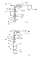
- FIG. 1 shown view perpendicular to the outer frame 60 and thus transverse to the longitudinal direction of a staple belt 10 in the mounting position shows the fastening device according to the invention.
- the tarpaulin to be fastened is not shown.
- the commercial vehicle with the loading area which would be located in the representation to the right of the fastening device and would therefore be loaded from the left side.
- the fastening device comprises a staple band 10 with staples 11, wherein in the illustration only one staple 11 can be seen.
- the staple band 10 further includes spacer brackets 12, the function of which will be described later.
- the staple band 10 is pivotally connected via a movement element 13 with a carrier 20.
- the carrier 20 is connected to the outer frame 60 via fastening means 30, 50.
- the outer frame 60 is provided with an upwardly directed nose 61 to which the carrier 20 correspondingly has a fastening arm 21 extending over the upwardly directed nose 61.
- the nose 61 essentially forms a loading edge 62 of the utility vehicle or of the outer frame 60, which surrounds the attachment arm 21.
- the attachment arm 21 is adapted directly to the shape of the loading edge or the outer frame 60.
- the carrier 20 has a substantially hook-shaped profile, wherein an upper, beveled portion of the carrier 20 forms the attachment arm 21.
- a lower portion of the carrier 20 is formed flat and is flush with a vertical outer wall of the outer frame 60 at.
- the lower portion of the carrier 20 has an outer surface 22 which extends substantially parallel to the outer frame 60 and to a vertical portion of the outer frame 60, respectively.
- the fastening means 30, 50 are arranged in the lower vertical portion of the carrier 20 and the outer frame 60.
- the fastening means preferably comprise screws or rivets. Alternatively it can be provided that the carrier 20 is welded to the outer frame 60.
- the outer frame 60 is preferably designed as a hole outer frame.
- recesses or holes are formed in the vertical section of the outer frame 60 at regular intervals, which on the one hand contribute to weight reduction and on the other hand serve as retaining elements for lashing means.
- the carrier 20 may extend over the entire outside of the outer frame 60 or, as shown in the figures, a comparatively narrow one Cover area of the outer frame 60, so that the carrier 20 can be arranged laterally next to a staple band 10 or between two staple bands 10.
- the attachment arm 21 covers the lug 61 of the outer frame 60, so that the attachment arm 21 is arranged substantially inside the commercial vehicle body.
- the mounting arm 21 extends into an interior of the commercial vehicle body, in particular into the cargo space of the commercial vehicle body. In the closed state of the tarpaulin of the commercial vehicle body of the mounting arm 21 is therefore arranged substantially inaccessible in the interior of the commercial vehicle body.
- the fastening device preferably has two carriers 20 which are arranged laterally next to the staple band 10 and are connected to the staple band 10 by the movement element 13. It is also possible for more than two carriers 20 to be provided, wherein, for example, a third carrier 20 may be arranged centrally between two sections of the staple band 10.
- the utility vehicle body or frame 60 may include a plurality of attachment devices.
- the movement element 13 forms an axis of rotation or pivot axis for the staple band 10, so that the staple band 10 can be pivoted over the carrier 20.
- the pivoting is preferably carried out automatically by releasing the tarpaulin from the staples 11.
- a locking of the staple tape 10 in the closed position is not provided.
- the staple band 10 may have on a back surface 15 magnetic elements that hold the staple band 10 in the closed position on the outer frame 60.
- locking elements, latches or fittings may be provided which are suitable for locking the staple tape 10 in the closed position.
- the staple band 10 has a front surface 14 from which the staples 11 rise.
- the front surface 14 points in the closed position away from the commercial vehicle body or forms a visible side surface of the commercial vehicle body.
- the back surface 15 of the spandex band 10 is disposed opposite the front surface 14.
- the back surface 15 extends parallel to the front surface 14.
- the carrier 20 is arranged in the closed position of the staple band 10 between the staple band 10 and the outer frame 60.
- the back surface 15 of the staple tape 10 then lies flush in the closed position on an outer surface 23 of the carrier 20.
- the carrier is preferably arranged laterally next to the staple band 10 in the closed position.
- the back surface 15 of the staple band 10 is aligned with an inner surface 22 of the carrier 20, wherein the inner surface 22 is flush with the outer frame 60.
- the carrier 20 and the staple band 10 may have the same material thickness so that the front surface 14 of the staple band 10 in the closed position is aligned with the outer surface 23 of the carrier.
- the loading position is preferably formed by the staple strap 10 facing the carrier 20 in such a way is deflected that the back surface 15 of the staple tape 10 is aligned with the outer surface 23 of the carrier 20, as in FIG. 2 shown. Accordingly, with the same material thicknesses, the front surface 14 of the staple band 10 can be aligned with the inner surface 22 of the carrier 20.
- Fig. 2 shows the identical arrangement, wherein the staple belt 10 is pivoted about the moving member 13 by 180 °.
- the staples 11 are therefore directed in the direction of the commercial vehicle body and the outer frame 60 and are therefore no longer contrary to the load coming from the left in the representation.
- a loading device In this lowered-down position, it is possible for a loading device to be moved up to the carrier 20 or the outer frame 60. As a result, the loading and unloading process is facilitated and yet prevents damage to both the staples 11 and such a loading device.
- spacer stirrups 12 can be provided, which provide mainly for increased stability of the staple ribbon 10.
- the tarpaulin is in the closed state on the spacer bracket 12, so that a uniform voltage of the tarpaulin achieved and the staple tape 10 is held in the closed position by the tarpaulin on the outer frame 60.
- the staple belt 10 fulfills a customs security function.
- a rope or a leash is guided and sealed by the staples 11 of the staple band 10, so that the eyelets of the tarpaulin passed over the staples 11 can not be released from the staples 11 without damaging the seal or the lead.
- the mechanical attachment or clamping of the tarpaulin is carried out by known tensioner, which are in the outer frame 60, in particular a lower edge of the outer frame 60, hooked.
- the staple band 10 is provided continuously along the outer frame 60 as a hinged-down element.
- the carrier 20 may consist of a single base plate which is connected to the outer frame 60 at several points, or of a plurality of support elements which are arranged at intervals along the curb and at the lower end of the movement member 13 is pivotally mounted.
- the movement element 13 can also be composed of separate movement means, such as a plurality of hinges.
- the staple strip 10 is dimensioned higher, so that it extends beyond the level of the loading edge 62 and loading area in the folded-up state. As a result, a lateral displacement of cargo, which is located on the bed, regardless of other safety measures prevented.
- the staple tape 10 is releasably fixed in its folded-up position via further - not shown in the figures - locking means.
- such locking means are also applicable to the other described embodiments.
- the carrier 20 is fixed on the one hand with fastening means 30, 50 on the outer frame 60. It is further provided that the mounting arm 21 of the carrier 20 is additionally fixed with a securing means 40 on the outer frame 60, in particular on the nose 61.
- the securing means may comprise a rivet.
- the securing means 40 may be formed according to the fastening means 30, 50. The securing means 40 is preferably accessible only from the loading space of the commercial vehicle body. As in FIG.
- the securing means 40 thus offers, in conjunction with the fastening arm 21, which projects into the cargo space of the commercial vehicle body, the possibility of providing a tamper-proof fastening device, so that a duty-proof closure of the commercial vehicle body is made possible.
Landscapes
- Engineering & Computer Science (AREA)
- Mechanical Engineering (AREA)
- Emergency Lowering Means (AREA)
- Connection Of Plates (AREA)
- Fittings On The Vehicle Exterior For Carrying Loads, And Devices For Holding Or Mounting Articles (AREA)
Abstract
Description
- Die Erfindung bezieht sich auf eine Befestigungsvorrichtung für einen Planenaufbau eines Nutzfahrzeugs sowie auf einen Nutzfahrzeugaufbau und ein Nutzfahrzeug mit einer derartigen Befestigungsvorrichtung.
- Die erfindungsgemäße Befestigungsvorrichtung dient zur Befestigung einer Plane, beispielsweise einer seitlichen Schiebegardine wie man sie an einem LKW oder LKW-Anhänger findet, und umfasst eine sogenannte Krampenanschlagsleiste, deren besondere Ausgestaltung eine deutliche Verbesserung gegenüber den aus dem Stand der Technik bekannten Befestigungssysteme für Planenaufbauten bietet.
- Aus dem Stand der Technik sind Planenaufbauten für LKWs, deren Anhänger und sonstige denkbare Ladeflächen grundsätzlich bekannt. Es gibt verschiedene Ausführungen, denen aber gemeinsam ist, dass sich eine Plane als Abdeckung von oben herab über Dachholme oder dergleichen erstreckt und an einer oberen Kante eines Außenrahmens der tragenden Struktur des Nutzfahrzeugs oder an einer sich aufwärts erstreckenden Bordwand lösbar befestigt werden soll. Dieses grundlegende System ist für Ladeflächen unterschiedlicher Größe identisch.
- Die
DE 29 20 644 A1 beschreibt eine Bordwand für den Aufbau von Nutzfahrzeugen, wobei ein Planösenprofil mit mindestens einem Führungsschlitz ausgebildet ist, in den eine Planösenstange oder dergleichen eingeschoben werden kann. Hierbei ist die Planösenstange mit mehreren Krampen bestückbar, die mit der Planösenstange beispielsweise vernietet, verschweißt oder verschraubt sind. Auch in derEP 0 825 049 B1 wird eine Verriegelungsvorrichtung für eine Plane beschrieben. Diese umfasst an der Plane befestigte Spanngurte, Spannhaken und mindestens eine Spannvorrichtung zwischen den Spanngurten und den Spannhaken, wobei die Spannhaken an einer gemeinsamen Welle angeordnet sind, die im Rahmen eines Fahrzeugs gelagert und mit der Spannvorrichtung verbunden ist. Ferner wird in derEP 1 710 108 A2 eine Vorhanganordnung für Fahrzeuge mit Seitenplane beschrieben, wobei die Seitenplane über eine Feder mit mehreren Befestigungsmitteln verbunden ist. Die Befestigungsmittel sind mittels Rollen verschiebbar in einer Schiene angeordnet. - Die vorliegende Erfindung geht von einer bekannten Anordnung aus, dass ein unterer, horizontal verlaufender Bereich der zu sichernden Plane mit dem Außenrahmen des Nutzfahrzeugs verbunden wird. Hierzu ist am Außenrahmen eine Leiste vorgesehen, auf der sich Befestigungsmittel befinden. Diese können beispielsweise in Gestalt von Krampen ausgebildet sein, die weitestgehend senkrecht zur Leiste aus dieser herausragen. Im befestigten Zustand der Plane können diese abstehenden Krampen durch Öffnungen in der Plane hindurchreichen, die entlang eines unteren, horizontal verlaufenden streifenförmigen Bereichs der Plane angeordnet sind. Im befestigten Zustand der Plane sind dann Sicherungsmittel an den Krampen angebracht, die ein Abgleiten der Plane von den Krampen verhindern. Um eine gleichmäßige Befestigung der Plane an der Leiste bzw. dem Außenrahmen zu gewährleisten, sind die Krampen vorzugsweise in regelmäßigen Abständen entlang der Leiste angebracht. Die aufzubringende Plane wiederum weist Öffnungen in entsprechenden Abständen auf, die ausreichend dimensioniert sind, um über die Krampen geschoben zu werden.
- Die erwähnten Sicherungsmittel bestehen in bekannten Fällen aus einzelnen Sicherungsmitteln, die jede Krampe separat absichern, oder vorzugsweise aus einer durchlaufenden Leine oder dergleichen, die entlang des Außenrahmens durch die Krampen hindurchgeschoben bzw. -gezogen wird. Die Plane befindet sich dann zwischen der Leine und der Leiste bzw. dem Außenrahmen.
- Der horizontal verlaufende Bereich, auf dem die aus der Leiste herausragenden Krampen angebracht sind, wird oftmals auch als "Krampenband", "Krampenanschlag" oder "Krampenanschlagsband" bezeichnet. Beim Beladen oder Entladen kommt es durch die exponierte Position der Krampen, die aus dem Krampenband herausragen, oftmals zu unerwünschten Beschädigungen sowohl an den Krampen als auch möglicherweise an den Beladungsvorrichtungen. Nachteilig ist außerdem, dass eine Beladungsvorrichtung gar nicht ganz bis an den Außenrahmen bzw. die Ladekante herangefahren werden kann.
- Um ein seitliches Verrutschen von Ladegut zusätzlich zu dessen Sicherung zu verhindern, weisen die oberen Kanten bzw. die Ladekante des Außenrahmens oftmals Erhöhungen gegenüber der Ladefläche auf. In jedem Fall weisen derartige Erhöhungen im beladenen und transportfertigen Zustand zwar eine klaren Vorteil hinsichtlich der Sicherung der Ladung auf; beim Vorgang des Beladens und des Entladens stellt eine derartige Erhöhung jedoch ein Hindernis für beispielsweise einen Gabelstapler oder sonstige Beladungsvorrichtungen dar. Auch hierdurch kann es zu Beschädigungen bei den Beladungsvorrichtungen und darüber hinaus auch am Ladegut kommen.
- Der Nachteil der aus der Praxis bekannten Befestigungsvorrichtungen, insbesondere Krampenbänder, besteht also darin, dass die funktionsbedingt notwendigen, aus dem Krampenband herausragenden Krampen leicht beschädigt werden und ebenso leicht Beschädigungen an den Beladungsvorrichtungen hervorrufen. Zu einer Sicherung des Ladegutes können sie generell nicht beitragen.
- Es ist somit Aufgabe der vorliegenden Erfindung, eine Befestigungsvorrichtung aufzuzeigen, die die beschriebenen Beschädigungen weitgehend verhindert. Gleichzeitig ist es ein weiteres Ziel, die bekannten Erhöhungen der Ladekanten zur Sicherung von Ladungsgut so zu integrieren, dass der Sicherungseffekt erhalten bleibt, jedoch die nachteilige Behinderung beim Be- und Entladungsvorgang entfällt.
- Ferner liegt der Erfindung die Aufgabe zugrunde, einen darauf abgestimmten Nutzfahrzeugaufbau und ein Nutzfahrzeug mit einem derartigen Nutzfahrzeugaufbau bzw. einer derartigen Befestigungsvorrichtung anzugeben.
- Erfindungsgemäß wird diese Aufgabe im Hinblick auf die Befestigungsvorrichtung durch den Gegenstand des Anspruchs 1, im Hinblick auf den Nutzfahrzeugaufbau durch den Gegenstand des Anspruchs 8 und im Hinblick auf das Nutzfahrzeug durch den Gegenstand des Anspruchs 15 gelöst.
- Die Erfindung beruht auf den Gedanken, eine Befestigungsvorrichtung für einen Planenaufbau eines Nutzfahrzeugs anzugeben. Die Befestigungsvorrichtung umfasst ein Krampenband mit einer Mehrzahl von Krampen, die aus dem Krampenband herausragen. Ferner weist die Befestigungsvorrichtung mindestens einen Träger und mindestens ein den Träger mit dem Krampenband verbindendes Bewegungselement auf. Das Bewegungselement wirkt mit dem Krampenband und mit dem Träger derart zusammen, dass das Krampenband von einer Verschlussposition, in der das Krampenband an dem Träger anliegt oder zumindest abschnittsweise mit dem Träger fluchtet, in eine Ladeposition verschwenkbar ist, in der das Krampenband gegenüber dem Träger ausgelenkt ist, insbesondere mit dem Träger fluchtet.
- Die der Erfindung zugrunde liegende Idee beruht darauf, eine Befestigungsvorrichtung umfassend ein Krampenband anzugeben, dass aus seiner für den Befestigungsvorgang notwendigen Position herausgeschwenkt werden kann. Dies geschieht vorzugsweise durch wenigstens ein Bewegungsmittel, das ein Schwenken des Krampenbandes um eine entlang des Krampenbandes an dessen unteren Ende verlaufende Achse ermöglicht, so dass im herabgeschwenkten Zustand die Krampen nicht mehr in einer von dem Außenrahmen abstehenden Richtung angeordnet sind, sondern nunmehr eine flache Rückseite des Krampenbandes auswärts zeigt und die auf dem Krampenband angeordneten Krampen in Richtung des Außenrahmens bzw. der Ladefläche unterhalb der Ladekante gerichtet sind. Der Träger kann in der Verschlussposition sowohl seitlich neben dem Krampenband (fluchtende Anordnung), als auch zwischen dem Krampenband und einem Außenrahmen eines Nutzfahrzeugs (anliegende Anordnung) positioniert sein.
- Der Vorteil der erfindungsgemäßen Befestigungsvorrichtung besteht darin, dass das Krampenband zum Be- und Entladen des Nutzfahrzeugs abklappbar ist, so dass eine Beschädigung der Krampen durch eine Beladungsvorrichtung oder die Beschädigung der Beladungsvorrichtung vermieden wird. Durch den Schwenkmechanismus, der den Wechsel zwischen der Verschlussposition und der Ladeposition des Krampenbandes bewirkt, ist eine einfache Handhabung sichergestellt. Die erfindungsgemäße Befestigungsvorrichtung ermöglicht also eine einfache und schnelle Fixierung einer Plane des Nutzfahrzeugs am Außenrahmen und gleichzeitig einen effizienten Be- und Entladevorgang, da in der abgeklappten Ladeposition ein Anfahren einer Beladungsvorrichtung direkt an die Ladekante bzw. den Außenrahmen des Nutzfahrzeugaufbaus ermöglicht ist.
- Die vorgenannten Vorteile kommen insbesondere dann zum Tragen, wenn der Träger gemäß einer bevorzugten Ausgestaltung der Erfindung mit einem Nutzfahrzeug, insbesondere mit einem Außenrahmen eines Nutzfahrzeugs, verbindbar ist.
- Konkret kann das Krampenband eine Frontfläche und eine Rückenfläche umfassen. Die Krampen sind vorzugsweise an der Frontfläche angeordnet. Die Rückenfläche kann in der Verschlussposition an einer Außenfläche des Trägers anliegen. Die Frontfläche weist also in der Verschlussposition von dem Außenrahmen bzw. der Ladefläche des Nutzfahrzeugs weg, so dass die Krampen nach außen vom Nutzfahrzeug abstehen. Die Rückenfläche, die vorzugsweise parallel zur Frontfläche angeordnet ist, liegt in der Verschlussposition bündig an der Außenfläche des Trägers an (Träger zwischen Krampenband und Nutzfahrzeug) oder fluchtet mit der Innenfläche des Trägers (Träger seitlich neben Krampenband). Vorzugsweise verlaufen sowohl die Frontfläche, als auch die Rückenfläche parallel entlang des Außenrahmens des Nutzfahrzeugs.
- In der Ladeposition kann die Rückenfläche mit der Außenfläche des Trägers fluchten. Mit anderen Worten ist die Rückenfläche in der Ladeposition vorzugsweise in derselben Ebene wie die Außenfläche des Trägers angeordnet. Dabei können die Rückenfläche und die Außenfläche gemeinsam eine Anschlagfläche bilden, die parallel zum Außenrahmen des Nutzfahrzeugs angeordnet ist. Eine Beladungsvorrichtung, beispielsweise ein Gabelstapler oder dergleichen, kann beim Be- und Entladen des Nutzfahrzeugs bis an die Anschlagfläche herangeführt werden.
- Gemäß einer bevorzugten Ausführungsform der erfindungsgemäßen Befestigungsvorrichtung weist der Träger einen Befestigungsarm auf, der zum Umgreifen einer Ladekante des Außenrahmens angepasst ist. Damit wird erreicht, dass zumindest ein Abschnitt des Trägers in einen Innenraum des Nutzfahrzeugs bzw. Nutzfahrzeugaufbaus hineinragt. Bei geschlossener Plane ist somit zumindest dieser Abschnitt des Trägers von außen nicht mehr erreichbar, so dass der Befestigungsarm eine zoll sichere Fixierung des Trägers an einem Nutzfahrzeug bzw. einem Außenrahmen ermöglicht.
- Das Krampenband kann ferner eine Höhe aufweisen, die höchstens die Höhe des Trägers entspricht. Dadurch wird vermieden, dass das Krampenband in der Verschlussposition über den Träger vorsteht bzw. den Träger überragt. Bei Anordnung der Befestigungsvorrichtung an einen Außenrahmen eines Nutzfahrzeugs wird auf diese Weise sichergestellt, dass die gesamte Ladeöffnung des Nutzfahrzeugs auch in der Verschlussposition des Krampenbands zugänglich ist.
- Alternativ kann das Krampenband eine Höhe aufweisen, die größer als die Höhe des Trägers ist. Das Krampenband kann den Träger überragen. Wenn die Befestigungsvorrichtung an einem Nutzfahrzeug, insbesondere einem Außenrahmen eines Nutzfahrzeugs angebracht ist, kann das Krampenband in der Verschlussposition zusätzlich zur Ladungssicherung, insbesondere als Palettenanschlag, genutzt werden. Dabei ist vorteilhafterweise vorgesehen, dass das Krampenband in der Verschlussposition arretierbar ist.
- Gemäß einem nebengeordneten Aspekt beruht die Erfindung auf dem Gedanken, einen Nutzfahrzeugaufbau umfassend eine zuvor beschriebene Befestigungsvorrichtung anzugeben.
- Der Nutzfahrzeugaufbau zeichnet sich in einer bevorzugten Ausgestaltung dadurch aus, dass der Träger der Befestigungsvorrichtung wenigstens ein Befestigungsmittel aufweist, das den Träger fest mit einem Außenrahmen des Nutzfahrzeugaufbaus verbindet. Als Befestigungsmittel sind insbesondere Schrauben oder Nieten vorgesehen. Die Verbindung zwischen dem Träger und dem Außenrahmen kann auch durch eine Schweißnaht erfolgen.
- Der Träger kann ferner wenigstens ein Sicherungsmittel aufweisen, das im Bereich des Befestigungsarms angeordnet ist. Das Sicherungsmittel kann den Träger manipulationssicher mit dem Außenrahmen verbinden. Vorzugsweise ist das Sicherungsmittel als Niet ausgebildet. Konkret ist vorgesehen, dass der Träger einen Befestigungsarm aufweist, der eine Ladekante des Außenrahmens umgreift.
- Das Sicherungsmittel fixiert den Befestigungsarm am Außenrahmen, wobei das Sicherungsmittel vorzugsweise von außerhalb des Nutzfahrzeugs bei geschlossener Plane unzugänglich ist.
- Insbesondere ist vorteilhafterweise vorgesehen, dass das Sicherungsmittel von außerhalb eines Laderaums des Nutzfahrzeugaufbaus unzugänglich und/oder ausschließlich zerstörend lösbar ist. Da das Sicherungsmittel zusätzlich im Befestigungsabschnitt angeordnet ist, der auch durch ein Hindurchgreifen der Plane im Wesentlichen nicht erreichbar ist, wird auf diese Weise eine zollsichere Verankerung des Krampenbands bzw. allgemein der Befestigungsvorrichtung erreicht. Das im Befestigungsabschnitt angeordnete Sicherungsmittel verhindert somit das unbefugte Lösen der Befestigungsvorrichtung und somit einen unbefugten Zugang zum Ladegut. Insbesondere ist die Befestigungsvorrichtung, konkret das Sicherungsmittel, derart angepasst, dass eine Demontage der Befestigungsvorrichtung ohne das Hinterlassen sichtbarer Spuren verhindert ist. Dazu ist vorgesehen, dass das Sicherungsmittel nur von einem Innenraum des Nutzfahrzeugs einsetzbar bzw. fixierbar ist. Somit wird verhindert, dass nach einer unbefugten Demontage der Befestigungsvorrichtung bei geschlossener Plane, wobei das Sicherungsmittel zerstört wird, die Befestigungsvorrichtung mit einem neuen Sicherungsmittel am Außenrahmen fixiert wird. Dies wäre nur möglich, wenn die Plane geöffnet werden kann, um die das neue Sicherungsmittel einbringenden Person aus dem Laderaum zu entlassen. Damit würde jedoch eine Zollplombe beschädigt werden, die üblicherweise an der durch die Plombe und die Krampen geführten Leine angebracht ist, so dass im Nachhinein erkennbar ist, falls ein unbefugter Zugriff auf das Ladegut bzw. in den Laderaum erfolgt ist.
- Bei einer weiteren bevorzugten Ausführungsform ist vorgesehen, dass die Krampen des Krampenbands in der Verschlussposition vom Außenrahmen des Nutzfahrzeugaufbaus wegragen und in der Ladeposition unterhalb des Außenrahmens angeordnet sind. Die Krampen behindern damit in der Ladeposition den Be- und Entladevorgang nicht.
- In einer besonders bevorzugten Ausgestaltung ist das Krampenband, insbesondere sind die Krampen, stets unterhalb einer Ladekante des Nutzfahrzeugaufbaus, insbesondere des Außenrahmens, angeordnet. Somit ist sichergestellt, dass die Plane im geschlossenen Zustand die gesamte Ladeöffnung des Nutzfahrzeugaufbaus überdeckt. Dies trägt einerseits zu einer Gewichtsersparnis bei, da auf starre Bordwände verzichtet werden kann, und ermöglicht andererseits eine flexible Öffnung des Nutzfahrzeugaufbaus, so dass Teile des Ladeguts schnell und effizient be- und entladen werden können. Auch bei nur teilweise Öffnung der Plane, insbesondere Seitenplane bzw. Schiebeplane, des Nutzfahrzeugaufbaus ist die vollständige Ladehöhe verfügbar, so dass einzelne Teile der Ladung schnell und effizient be- und entladen werden können.
- Alternativ kann vorgesehen sein, dass das Krampenband in der Verschlussposition vertikal über die Ladekante des Nutzfahrzeugaufbaus, insbesondere des Außenrahmens, vorsteht. Dabei können die Krampen sowohl in der Verschlussposition, als auch in der Ladeposition des Krampenbands unterhalb der Ladekante angeordnet sein. Das in der Verschlussposition vertikal über die Ladekante vorstehende Krampenband kann zur Ladungssicherung, insbesondere als Palettenanschlag, dienen.
- Gemäß einem weiteren nebengeordneten Aspekt beruht die Erfindung auf dem Gedanken, ein Nutzfahrzeug mit einer eingangs erläuterten Befestigungsvorrichtung oder einem zuvor beschriebenen Nutzfahrzeugaufbau anzugeben.
- Die Erfindung wird im Folgenden anhand von Ausführungsbeispielen unter Bezugnahme auf die beigefügten, schematischen Zeichnungen näher erläutert. Darin zeigen
-
Fig. 1 eine Querschnittsansicht einer erfindungsgemäßen Befestigungsvorrichtung gemäß einem bevorzugten Ausführungsbeispiel in Verbindung mit einem Außenrahmen eines Nutzfahrzeugaufbaus, wobei das Krampenband in der Verschlussposition angeordnet ist; und -
Fig. 2 eine Querschnittsansicht der Befestigungsvorrichtung gemäßFigur 1 , wobei das Krampenband in der Ladeposition angeordnet ist. - In der nachfolgenden Beschreibung werden für gleiche und gleich wirkende Teile dieselben Bezugsziffern verwendet.
- Die in
Fig. 1 gezeigte Ansicht senkrecht zum Außenrahmen 60 und somit quer zur Längsrichtung eines Krampenbandes 10 in Montageposition zeigt die erfindungsgemäße Befestigungsvorrichtung. Die zu befestigende Plane ist dabei nicht dargestellt. Ebenso nicht gezeigt ist das Nutzfahrzeug mit der Ladefläche, die sich in der Darstellung rechts von der Befestigungsvorrichtung befinden würde und demzufolge von der linken Seite zu beladen wäre. Die Befestigungsvorrichtung umfasst ein Krampenband 10 mit Krampen 11, wobei in der Darstellung nur eine Krampe 11 erkennbar ist. Das Krampenband 10 weist ferner Abstandsbügel 12 auf, deren Funktion später beschrieben wird. Das Krampenband 10 ist über ein Bewegungselement 13 mit einem Träger 20 schwenkbar verbunden. Der Träger 20 ist mit dem Außenrahmen 60 über Befestigungsmittel 30, 50 verbunden. In der Darstellung derFig. 1 ist der Außenrahmen 60 mit einer aufwärtsgerichteten Nase 61 versehen, zu der korrespondierend der Träger 20 einen über die aufwärts gerichtete Nase 61 reichenden Befestigungsarm 21 aufweist. Die Nase 61 bildet im Wesentlichen eine Ladekante 62 des Nutzfahrzeugs bzw. des Außenrahmens 60, die der Befestigungsarm 21 umgreift. Der Befestigungsarm 21 ist direkt an die Form der Ladekante bzw. des Außenrahmens 60 angepasst. - Insgesamt weist der Träger 20 ein im Wesentlichen hakenförmiges Profil auf, wobei ein oberer, abgekanteter Abschnitt des Trägers 20 den Befestigungsarm 21 bildet. Ein unterer Abschnitt des Trägers 20 ist flach ausgebildet und liegt bündig an einer vertikalen Außenwand des Außenrahmens 60 an. Der untere Abschnitt des Trägers 20 weist eine Außenfläche 22 auf, die sich im Wesentlichen parallel zum Außenrahmen 60 bzw. zu einem vertikalen Abschnitt des Außenrahmens 60 erstreckt. Ferner sind im unteren vertikalen Abschnitt des Trägers 20 bzw. des Außenrahmens 60 die Befestigungsmittel 30, 50 angeordnet. Die Befestigungsmittel umfassen vorzugsweise Schrauben oder Nieten. Alternativ kann vorgesehen sein, dass der Träger 20 mit dem Außenrahmen 60 verschweißt ist.
- Der Außenrahmen 60 ist vorzugsweise als Lochaußenrahmen ausgeführt. Dabei sind im vertikalen Abschnitt des Außenrahmens 60 in regelmäßigen Abständen Ausnehmungen bzw. Löcher ausgebildet, die einerseits zur Gewichtsreduktion beitragen und andererseits als Halteelemente für Verzurrmittel dienen.
- Der Träger 20 kann sich über die gesamte Außenseite des Außenrahmens 60 erstrecken, oder, wie in den Figuren dargestellt, einen vergleichsweise schmalen Bereich des Außenrahmens 60 abdecken, so dass der Träger 20 seitlich neben einem Krampenband 10 oder zwischen zwei Krampenbändern 10 anordenbar ist. Der Befestigungsarm 21 überdeckt die Nase 61 des Außenrahmens 60, so dass der Befestigungsarm 21 im Wesentlichen innerhalb des Nutzfahrzeugaufbaus angeordnet ist. Konkret erstreckt sich der Befestigungsarm 21 in einen Innenraum des Nutzfahrzeugaufbaus, insbesondere in den Laderaum des Nutzfahrzeugaufbaus, hinein. Im geschlossenen Zustand der Plane des Nutzfahrzeugaufbaus ist der Befestigungsarm 21 daher im Wesentlichen unzugänglich im Innenraum des Nutzfahrzeugaufbaus angeordnet.
- Vorzugsweise weist die Befestigungsvorrichtung zwei Träger 20 auf, die seitlich neben dem Krampenband 10 angeordnet und mit dem Krampenband 10 durch das Bewegungselement 13 verbunden sind. Es ist auch möglich, dass mehr als zwei Träger 20 vorgesehen sind, wobei beispielsweise ein dritter Träger 20 mittig zwischen zwei Abschnitten des Krampenbands 10 angeordnet sein kann. Der Nutzfahrzeug-aufbau bzw. der Außenrahmen 60 kann mehrere Befestigungsvorrichtungen umfassen.
- Das Bewegungselement 13 bildet eine Drehachse bzw. Schwenkachse für das Krampenband 10, so dass das Krampenband 10 über dem Träger 20 verschwenkbar ist. Das Verschwenken erfolgt vorzugsweise selbsttätig durch Lösen der Plane von den Krampen 11. Eine Arretierung des Krampenbandes 10 in der Verschlussposition ist nicht vorgesehen. Es ist jedoch durchaus möglich, eine Arretierung des Krampenbands 10 in der Verschlussposition durch geeignete Maßnahmen zu erreichen. Beispielsweise kann das Krampenband 10 an einer Rückenfläche 15 magnetische Elemente aufweisen, die das Krampenband 10 in der Verschlussposition am Außenrahmen 60 halten. Alternativ können Rastelemente, Riegel oder Beschläge vorgesehen sein, die zur Arretierung des Krampenbands 10 in der Verschlussposition geeignet sind.
- Das Krampenband 10 weist eine Frontfläche 14 auf, aus der sich die Krampen 11 erheben. Die Frontfläche 14 weist in der Verschlussposition vom Nutzfahrzeugaufbau weg bzw. bildet eine sichtbare Seitenfläche des Nutzfahrzeugaufbaus. Die Rückenfläche 15 des Krampenbands 10 ist der Frontfläche 14 gegenüber angeordnet. Insbesondere erstreckt sich die Rückenfläche 15 parallel zur Frontfläche 14. In der Verschlussposition liegt die Rückenfläche 15 bündig am Außenrahmen 60, insbesondere an einer vertikalen Außenwand des Außenrahmens 60 an, wie in
Figur 1 gezeigt. Alternativ kann vorgesehen sein, dass der Träger 20 in der Verschlussposition des Krampenbands 10 zwischen dem Krampenband 10 und dem Außenrahmen 60 angeordnet ist. Die Rückenfläche 15 des Krampenbandes 10 liegt dann in der Verschlussposition bündig an einer Außenfläche 23 des Trägers 20 an. - Vorzugsweise ist der Träger jedoch seitlich neben den Krampenband 10 in der Verschlussposition angeordnet. Dabei fluchtet die Rückenfläche 15 des Krampenbands 10 mit einer Innenfläche 22 des Trägers 20, wobei die Innenfläche 22 bündig am Außenrahmen 60 anliegt. Der Träger 20 und das Krampenband 10 können dieselbe Materialstärke aufweisen, so dass die Frontfläche 14 des Krampenbands 10 in der Verschlussposition mit der Außenfläche 23 des Trägers fluchtet.
- Bei beiden vorgenannten Varianten, wobei der Träger 20 entweder seitlich neben dem Krampenband 10 angeordnet ist oder sich der Träger 20 in der Verschlussposition zwischen den Krampenband und dem Außenrahmen 60 erstreckt, ist die Ladeposition vorzugsweise dadurch gebildet, dass das Krampenband 10 gegenüber dem Träger 20 derart ausgelenkt ist, dass die Rückenfläche 15 des Krampenbands 10 mit der Außenfläche 23 des Trägers 20 fluchtet, wie in
Figur 2 dargestellt. Entsprechend kann, bei gleichen Materialstärken, die Frontfläche 14 des Krampenbands 10 mit der Innenfläche 22 des Trägers 20 fluchten. -
Fig. 2 zeigt die identische Anordnung, wobei das Krampenband 10 über das Bewegungselement 13 um 180° herabgeschwenkt ist. Die Krampen 11 sind daher in Richtung des Nutzfahrzeugaufbaus bzw. des Außenrahmens 60 gerichtet und stehen demzufolge nicht mehr der in der Darstellung von links kommenden Beladung entgegen. In dieser herabgeschwenkten Position ist es möglich, dass eine Beladungsvorrichtung bis an den Träger 20 bzw. den Außenrahmen 60 herangefahren wird. Dadurch wird der Beladungs- und Entladungsvorgang erleichtert und dennoch eine Beschädigung sowohl der Krampen 11 als auch einer solchen Beladungsvorrichtung verhindert. Um zu vermeiden, dass die Krampen 11 im herabgeklappten Zustand direkt am Außenrahmen 60 anliegen können Abstandsbügel 12 vorgesehen sein, die hauptsächlich für eine erhöhte Stabilität des Krampenbands 10 sorgen. Ferner liegt die Plane im geschlossenen Zustand an dem Abstandsbügel 12 an, so dass eine gleichmäßige Spannung der Plane erreicht und das Krampenband 10 in der Verschlussposition durch die Plane am Außenrahmen 60 gehalten wird. - Im Allgemeinen ist vorgesehen, dass das Krampenband 10 eine Zollsicherheitsfunktion erfüllt. Konkret wird durch die Krampen 11 des Krampenbands 10 ein Seil oder eine Leine geführt und verplombt, so dass die über die Krampen 11 geführten Ösen der Plane nicht ohne eine Beschädigung der Plombe oder der Leine von den Krampen 11 gelöst werden können. Die mechanische Befestigung bzw. das Spannen der Plane erfolgt durch an sich bekannte Planenspanner, die in den Außenrahmen 60, insbesondere eine untere Kante des Außenrahmens 60, eingehakt werden.
- Grundsätzlich ist das Krampenband 10 zwar durchlaufend entlang des Außenrahmens 60 als ein herunterklappbares Element vorgesehen. Dies bedeutet aber nicht, dass auch der Träger 20 zwingend aus einem durchlaufenden Streifen bestehen muss. Vielmehr kann der Träger 20 zwar aus einer einzigen Grundplatte bestehen, die an mehreren Stellen mit dem Außenrahmen 60 verbunden ist, oder aber aus mehreren Trägerelementen, die in Abständen entlang der Bordkante angeordnet sind und an deren unteren Ende das Bewegungselement 13 schwenkbar befestigt ist. Auch das Bewegungselement 13 kann sich aus separaten Bewegungsmitteln, wie beispielsweise mehreren Scharnieren, zusammensetzen.
- In einer weiteren, in den Figuren nicht erkennbaren, Ausführungsform ist das Krampenband 10 höher dimensioniert, so dass es im heraufgeklappten Zustand über das Niveau der Ladekante 62 bzw. Ladefläche hinausreicht. Dadurch wird ein seitliches Verschieben von Ladegut, das sich auf der Ladefläche befindet, unabhängig von sonstigen Sicherungsmaßnahmen verhindert. Hierfür wird das Krampenband 10 über weitere - in den Figuren nicht dargestellte- Arretierungsmittel in seiner heraufgeklappten Position lösbar fixiert. Derartige Arretierungsmittel sind jedoch auch für die anderen beschriebenen Ausführungsformen einsetzbar.
- Wie in den
Figuren 1 und 2 zu erkennen ist, ist der Träger 20 einerseits mit Befestigungsmitteln 30, 50 an dem Außenrahmen 60 fixiert. Ferner ist vorgesehen, dass der Befestigungsarm 21 des Trägers 20 zusätzlich mit einem Sicherungsmittel 40 am Außenrahmen 60, insbesondere an der Nase 61, fixiert ist. Das Sicherungsmittel kann einen Niet umfassen. Im Allgemeinen kann das Sicherungsmittel 40 entsprechend den Befestigungsmitteln 30, 50 ausgebildet sein. Das Sicherungsmittel 40 ist vorzugsweise ausschließlich vom Laderaum des Nutzfahrzeugaufbaus zugänglich. Wie inFigur 1 gut erkennbar ist, bildet der Abstandsbügel 12 in der Verschlussposition des Krampenbands 10 nicht nur einen Abstandshalter für die Plane des Nutzfahrzeugaufbaus, sondern dient gleichzeitig als Durchgriffschutz, so dass ein unbefugter Zugriff auf das Sicherungsmittel 40 im geschlossenen Zustand des Nutzfahrzeugaufbaus, also bei geschlossener Plane, verhindert ist. Das Sicherungsmittel 40 bietet somit in Verbindung mit den Befestigungsarm 21, der in den Laderaum des Nutzfahrzeugaufbaus hineinragt, die Möglichkeit, eine manipulationssichere Befestigungsvorrichtung vorzusehen, so dass ein zollsicherer Verschluss des Nutzfahrzeugaufbaus ermöglicht ist. -
- 10
- Krampenband
- 11
- Krampe
- 12
- Abstandsbügel
- 13
- Bewegungselement
- 14
- Frontfläche
- 15
- Rückenfläche
- 20
- Träger
- 21
- Befestigungsarm
- 22
- Innenfläche
- 23
- Außenfläche
- 30, 50
- Befestigungsmittel
- 40
- Sicherungsmittel
- 60
- Profilelement
- 61
- Nase
- 62
- Ladekante
Claims (15)
- Befestigungsvorrichtung für einen Planenaufbau eines Nutzfahrzeugs, wobei die Befestigungsvorrichtung ein Krampenband (10) mit einer Mehrzahl von Krampen (11) umfasst, die aus dem Krampenband (10) herausragen, gekennzeichnet durch
mindestens einen Träger (20) und mindestens ein den Träger (20) mit dem Krampenband (10) verbindendes Bewegungselement (13) zum Verschwenken des Krampenbands (10) von einer Verschlussposition, in der das Krampenband (10) an dem Träger (20) anliegt oder zumindest abschnittsweise mit dem Träger (20) fluchtet, in eine Ladeposition, in der das Krampenband (10) gegenüber dem Träger (20) ausgelenkt ist. - Befestigungsvorrichtung nach Anspruch 1,
dadurch gekennzeichnet, dass
der Träger (20) mit einem Nutzfahrzeug, insbesondere mit einem Außenrahmen (60) eines Nutzfahrzeugs, verbindbar ist. - Befestigungsvorrichtung nach Anspruch 1 oder 2,
dadurch gekennzeichnet, dass
das Krampenband (10) eine Frontfläche (14) und eine Rückenfläche (15) umfasst, wobei die Krampen (11) an der Frontfläche angeordnet sind und die Rückenfläche in der Verschlussposition mit einer Innenfläche (22) des Trägers (20) fluchtet oder an einer Außenfläche (23) des Trägers bündig anliegt. - Befestigungsvorrichtung nach Anspruch 3,
dadurch gekennzeichnet, dass
die Rückenfläche (15) in der Ladeposition mit einer Außenfläche (23) des Trägers (20) fluchtet. - Befestigungsvorrichtung nach einem der Ansprüche 1 bis 4,
dadurch gekennzeichnet, dass
der Träger (20) einen Befestigungsarm (21) aufweist, der zum Umgreifen einer Ladekante (62) des Außenrahmens (60) angepasst ist. - Befestigungsvorrichtung nach einem der Ansprüche 1 bis 5,
dadurch gekennzeichnet, dass
das Krampenband (10) eine Höhe aufweist, die höchstens der Höhe des Trägers (20) entspricht. - Befestigungsvorrichtung nach einem der Ansprüche 1 bis 5,
dadurch gekennzeichnet, dass
das Krampenband (10) eine Höhe aufweist, die größer als die Höhe des Trägers (20) ist. - Nutzfahrzeugaufbau umfassend eine Befestigungsvorrichtung nach einem der Ansprüche 1 bis 4.
- Nutzfahrzeugaufbau nach Anspruch 8,
dadurch gekennzeichnet, dass
der Träger (20) wenigstens ein Befestigungsmittel (30, 50) aufweist, das den Träger (20) fest mit einem Außenrahmen (60) des Nutzfahrzeugaufbaus verbindet. - Nutzfahrzeugaufbau nach Anspruch 8 oder 9,
dadurch gekennzeichnet, dass
der Träger (20) wenigstens ein Sicherungsmittel (40) aufweist, das im Bereich des Befestigungsarms (21) angeordnet ist und den Träger (20) manipulationssicher mit dem Außenrahmen (60) verbindet. - Nutzfahrzeugaufbau nach Anspruch 10,
dadurch gekennzeichnet, dass
das Sicherungsmittel (40) von außerhalb eines Laderaums des Nutzfahrzeugaufbaus unzugänglich und/oder ausschließlich zerstörend lösbar ist. - Nutzfahrzeugaufbau nach einem der Ansprüche 8 bis 11,
dadurch gekennzeichnet, dass
die Krampen (11) des Krampenbands (10) in der Verschlussposition vom Außenrahmen (60) des Nutzfahrzeugaufbaus wegragen und in der Ladeposition unterhalb des Außenrahmens (60) angeordnet sind. - Nutzfahrzeugaufbau nach einem der Ansprüche 8 bis 12,
dadurch gekennzeichnet, dass
das Krampenband (10), insbesondere die Krampen (11), stets unterhalb einer Ladekante (62) des Nutzfahrzeugaufbaus, insbesondere des Außenrahmens (60), angeordnet ist. - Nutzfahrzeugaufbau nach einem der Ansprüche 8 bis 12,
dadurch gekennzeichnet, dass
das Krampenband (10) in der Verschlussposition vertikal über eine Ladekante (62) des Nutzfahrzeugaufbaus, insbesondere des Außenrahmens (60), vorsteht. - Nutzfahrzeug mit einer Befestigungsvorrichtung nach einem der Ansprüche 1 bis 7 oder einem Nutzfahrzeugaufbau nach einem der Ansprüche 8 bis 14.
Applications Claiming Priority (1)
| Application Number | Priority Date | Filing Date | Title |
|---|---|---|---|
| DE102010045524A DE102010045524A1 (de) | 2010-09-15 | 2010-09-15 | Befestigungsvorrichtung für einen Planenaufbau eines Nutzfahrzeugs, Nutzfahrzeugaufbau und Nutzfahrzeug mit einer derartigen Befestigungsvorrichtung |
Publications (3)
| Publication Number | Publication Date |
|---|---|
| EP2431205A2 true EP2431205A2 (de) | 2012-03-21 |
| EP2431205A3 EP2431205A3 (de) | 2015-05-27 |
| EP2431205B1 EP2431205B1 (de) | 2016-05-04 |
Family
ID=44651316
Family Applications (1)
| Application Number | Title | Priority Date | Filing Date |
|---|---|---|---|
| EP11181328.3A Active EP2431205B1 (de) | 2010-09-15 | 2011-09-15 | Befestigungsvorrichtung für einen Planenaufbau eines Nutzfahrzeugs, Nutzfahrzeugaufbau und Nutzfahrzeug mit einer derartigen Befestigungsvorrichtung |
Country Status (3)
| Country | Link |
|---|---|
| EP (1) | EP2431205B1 (de) |
| DE (1) | DE102010045524A1 (de) |
| PL (1) | PL2431205T3 (de) |
Cited By (1)
| Publication number | Priority date | Publication date | Assignee | Title |
|---|---|---|---|---|
| EP3398811A1 (de) * | 2017-03-14 | 2018-11-07 | "WIELTON" Spolka Akcyjna | Funktionsprofil für ein kraftfahrzeug |
Families Citing this family (1)
| Publication number | Priority date | Publication date | Assignee | Title |
|---|---|---|---|---|
| DE102012016861B4 (de) * | 2012-08-25 | 2015-03-05 | Man Truck & Bus Ag | Anordnung einer Anbauplatten-Abdeckung an einer Frontanbauplatte eines Fahrzeugs, insbesondere eines Nutzfahrzeugs |
Citations (3)
| Publication number | Priority date | Publication date | Assignee | Title |
|---|---|---|---|---|
| DE2920644A1 (de) | 1979-05-22 | 1980-12-04 | Krone Bernhard Gmbh Maschf | Bordwand fuer den fahrzeugaufbau von nutzfahrzeugen |
| EP0825049B1 (de) | 1996-08-21 | 2002-05-15 | MBFL Fliegl GmbH | Verriegelungsvorrichtung für eine Plane |
| EP1710108A2 (de) | 2005-04-07 | 2006-10-11 | Schmitz Cargobull (UK) Limited | Vorhanganordnung für Fahrzeug mit Seitenplane |
Family Cites Families (3)
| Publication number | Priority date | Publication date | Assignee | Title |
|---|---|---|---|---|
| GB1256892A (de) * | 1968-03-01 | 1971-12-15 | ||
| ATE106045T1 (de) * | 1990-07-05 | 1994-06-15 | Alusuisse Lonza Services Ag | Planenkrampe. |
| DE20110543U1 (de) * | 2001-06-26 | 2001-10-25 | Sommer Fahrzeugbau GmbH + Co KG, 33649 Bielefeld | Lastfahrzeug-Aufbau |
-
2010
- 2010-09-15 DE DE102010045524A patent/DE102010045524A1/de not_active Withdrawn
-
2011
- 2011-09-15 EP EP11181328.3A patent/EP2431205B1/de active Active
- 2011-09-15 PL PL11181328.3T patent/PL2431205T3/pl unknown
Patent Citations (3)
| Publication number | Priority date | Publication date | Assignee | Title |
|---|---|---|---|---|
| DE2920644A1 (de) | 1979-05-22 | 1980-12-04 | Krone Bernhard Gmbh Maschf | Bordwand fuer den fahrzeugaufbau von nutzfahrzeugen |
| EP0825049B1 (de) | 1996-08-21 | 2002-05-15 | MBFL Fliegl GmbH | Verriegelungsvorrichtung für eine Plane |
| EP1710108A2 (de) | 2005-04-07 | 2006-10-11 | Schmitz Cargobull (UK) Limited | Vorhanganordnung für Fahrzeug mit Seitenplane |
Cited By (1)
| Publication number | Priority date | Publication date | Assignee | Title |
|---|---|---|---|---|
| EP3398811A1 (de) * | 2017-03-14 | 2018-11-07 | "WIELTON" Spolka Akcyjna | Funktionsprofil für ein kraftfahrzeug |
Also Published As
| Publication number | Publication date |
|---|---|
| PL2431205T3 (pl) | 2016-11-30 |
| EP2431205A3 (de) | 2015-05-27 |
| EP2431205B1 (de) | 2016-05-04 |
| DE102010045524A1 (de) | 2012-03-15 |
Similar Documents
| Publication | Publication Date | Title |
|---|---|---|
| EP0925975B1 (de) | Fahrzeugaufbau für Nutzfahrzeuge | |
| DE202008016326U1 (de) | Vorrichtung zur Sicherung von Ladung | |
| DE19756865B4 (de) | Nutzfahrzeugaufbau | |
| DE102013201003A1 (de) | Längsgurt für Schiebeverdeckstruktur und Schiebeverdeckstruktur | |
| DE202012104195U1 (de) | Nutzfahrzeugaufbau mit mindestens einer Seitenplane | |
| EP2330020B1 (de) | Seitenabdeckung eines Nutzfahrzeugaufbaus | |
| DE102015108782B4 (de) | Fahrzeugaufbau, insbesondere für Nutzfahrzeuge, Nutzfahrzeug mit einem solchen Fahrzeugaufbau und Herstellungsverfahren | |
| DE102010012685B4 (de) | Fahrzeugaufbau | |
| EP2431205B1 (de) | Befestigungsvorrichtung für einen Planenaufbau eines Nutzfahrzeugs, Nutzfahrzeugaufbau und Nutzfahrzeug mit einer derartigen Befestigungsvorrichtung | |
| EP2266825B1 (de) | Transportfahrzeug mit Zollverschlussvorrichtung | |
| DE102008019162B4 (de) | Fahrzeugaufbau | |
| EP3170721A1 (de) | Spriegelkonstruktion, aufbau für nutzfahrzeuge, wechselbrücke, und nutzfahrzeug mit aufbau | |
| DE10226067A1 (de) | Lastfahrzeug-Aufbau | |
| EP3398811B1 (de) | Funktionsprofil für ein kraftfahrzeug | |
| EP4267431B1 (de) | Plane und nutzfahrzeug mit einer solchen plane | |
| DE102019101047B4 (de) | Nutzfahrzeugaufbau und Nutzfahrzeug mit einem derartigen Nutzfahrzeugaufbau | |
| DE102013201004A1 (de) | Rollenwagen und modulares Baukastensystem für einen Rollenwagen für eine Schiebeverdeckstruktur eines Lastwagens | |
| EP3015311B1 (de) | Nutzfahrzeugaufbau und Verfahren zum Sichern der Lage eines Transportguts auf einer Ladefläche eines Nutzfahrzeugs | |
| EP3069929B1 (de) | Verwendung eines Lochs in einem Querträger | |
| EP2218657B1 (de) | Planenaufbau eines Nutzfahrzeugs | |
| DE102016115786B4 (de) | Ladungssicherungseinrichtung für Nutzfahrzeuge | |
| DE102011117441A1 (de) | Vorrichtung zur Halterung von wenigstens einem Transportsicherungsnetz, in einem Fahrzeug | |
| DE102017129531B4 (de) | Nutzfahrzeugaufbau und Nutzfahrzeug mit einem solchen Nutzfahrzeugaufbau | |
| DE202006006168U1 (de) | Ladegutsicherung an Transportfahrzeugen | |
| EP3546260B1 (de) | Planenverschlusselement, plane und fahrzeugaufbau |
Legal Events
| Date | Code | Title | Description |
|---|---|---|---|
| PUAI | Public reference made under article 153(3) epc to a published international application that has entered the european phase |
Free format text: ORIGINAL CODE: 0009012 |
|
| AK | Designated contracting states |
Kind code of ref document: A2 Designated state(s): AL AT BE BG CH CY CZ DE DK EE ES FI FR GB GR HR HU IE IS IT LI LT LU LV MC MK MT NL NO PL PT RO RS SE SI SK SM TR |
|
| AX | Request for extension of the european patent |
Extension state: BA ME |
|
| PUAL | Search report despatched |
Free format text: ORIGINAL CODE: 0009013 |
|
| AK | Designated contracting states |
Kind code of ref document: A3 Designated state(s): AL AT BE BG CH CY CZ DE DK EE ES FI FR GB GR HR HU IE IS IT LI LT LU LV MC MK MT NL NO PL PT RO RS SE SI SK SM TR |
|
| AX | Request for extension of the european patent |
Extension state: BA ME |
|
| RIC1 | Information provided on ipc code assigned before grant |
Ipc: B60J 5/06 20060101AFI20150417BHEP |
|
| 17P | Request for examination filed |
Effective date: 20150610 |
|
| RBV | Designated contracting states (corrected) |
Designated state(s): AL AT BE BG CH CY CZ DE DK EE ES FI FR GB GR HR HU IE IS IT LI LT LU LV MC MK MT NL NO PL PT RO RS SE SI SK SM TR |
|
| GRAP | Despatch of communication of intention to grant a patent |
Free format text: ORIGINAL CODE: EPIDOSNIGR1 |
|
| INTG | Intention to grant announced |
Effective date: 20151130 |
|
| GRAS | Grant fee paid |
Free format text: ORIGINAL CODE: EPIDOSNIGR3 |
|
| GRAA | (expected) grant |
Free format text: ORIGINAL CODE: 0009210 |
|
| AK | Designated contracting states |
Kind code of ref document: B1 Designated state(s): AL AT BE BG CH CY CZ DE DK EE ES FI FR GB GR HR HU IE IS IT LI LT LU LV MC MK MT NL NO PL PT RO RS SE SI SK SM TR |
|
| REG | Reference to a national code |
Ref country code: GB Ref legal event code: FG4D Free format text: NOT ENGLISH |
|
| REG | Reference to a national code |
Ref country code: CH Ref legal event code: EP |
|
| REG | Reference to a national code |
Ref country code: AT Ref legal event code: REF Ref document number: 796580 Country of ref document: AT Kind code of ref document: T Effective date: 20160515 |
|
| REG | Reference to a national code |
Ref country code: IE Ref legal event code: FG4D Free format text: LANGUAGE OF EP DOCUMENT: GERMAN |
|
| REG | Reference to a national code |
Ref country code: DE Ref legal event code: R096 Ref document number: 502011009638 Country of ref document: DE |
|
| REG | Reference to a national code |
Ref country code: NL Ref legal event code: MP Effective date: 20160504 |
|
| REG | Reference to a national code |
Ref country code: LT Ref legal event code: MG4D |
|
| PG25 | Lapsed in a contracting state [announced via postgrant information from national office to epo] |
Ref country code: LT Free format text: LAPSE BECAUSE OF FAILURE TO SUBMIT A TRANSLATION OF THE DESCRIPTION OR TO PAY THE FEE WITHIN THE PRESCRIBED TIME-LIMIT Effective date: 20160504 Ref country code: NL Free format text: LAPSE BECAUSE OF FAILURE TO SUBMIT A TRANSLATION OF THE DESCRIPTION OR TO PAY THE FEE WITHIN THE PRESCRIBED TIME-LIMIT Effective date: 20160504 Ref country code: NO Free format text: LAPSE BECAUSE OF FAILURE TO SUBMIT A TRANSLATION OF THE DESCRIPTION OR TO PAY THE FEE WITHIN THE PRESCRIBED TIME-LIMIT Effective date: 20160804 Ref country code: FI Free format text: LAPSE BECAUSE OF FAILURE TO SUBMIT A TRANSLATION OF THE DESCRIPTION OR TO PAY THE FEE WITHIN THE PRESCRIBED TIME-LIMIT Effective date: 20160504 |
|
| PG25 | Lapsed in a contracting state [announced via postgrant information from national office to epo] |
Ref country code: PT Free format text: LAPSE BECAUSE OF FAILURE TO SUBMIT A TRANSLATION OF THE DESCRIPTION OR TO PAY THE FEE WITHIN THE PRESCRIBED TIME-LIMIT Effective date: 20160905 Ref country code: RS Free format text: LAPSE BECAUSE OF FAILURE TO SUBMIT A TRANSLATION OF THE DESCRIPTION OR TO PAY THE FEE WITHIN THE PRESCRIBED TIME-LIMIT Effective date: 20160504 Ref country code: ES Free format text: LAPSE BECAUSE OF FAILURE TO SUBMIT A TRANSLATION OF THE DESCRIPTION OR TO PAY THE FEE WITHIN THE PRESCRIBED TIME-LIMIT Effective date: 20160504 Ref country code: LV Free format text: LAPSE BECAUSE OF FAILURE TO SUBMIT A TRANSLATION OF THE DESCRIPTION OR TO PAY THE FEE WITHIN THE PRESCRIBED TIME-LIMIT Effective date: 20160504 Ref country code: HR Free format text: LAPSE BECAUSE OF FAILURE TO SUBMIT A TRANSLATION OF THE DESCRIPTION OR TO PAY THE FEE WITHIN THE PRESCRIBED TIME-LIMIT Effective date: 20160504 Ref country code: SE Free format text: LAPSE BECAUSE OF FAILURE TO SUBMIT A TRANSLATION OF THE DESCRIPTION OR TO PAY THE FEE WITHIN THE PRESCRIBED TIME-LIMIT Effective date: 20160504 Ref country code: GR Free format text: LAPSE BECAUSE OF FAILURE TO SUBMIT A TRANSLATION OF THE DESCRIPTION OR TO PAY THE FEE WITHIN THE PRESCRIBED TIME-LIMIT Effective date: 20160805 |
|
| PG25 | Lapsed in a contracting state [announced via postgrant information from national office to epo] |
Ref country code: DK Free format text: LAPSE BECAUSE OF FAILURE TO SUBMIT A TRANSLATION OF THE DESCRIPTION OR TO PAY THE FEE WITHIN THE PRESCRIBED TIME-LIMIT Effective date: 20160504 Ref country code: EE Free format text: LAPSE BECAUSE OF FAILURE TO SUBMIT A TRANSLATION OF THE DESCRIPTION OR TO PAY THE FEE WITHIN THE PRESCRIBED TIME-LIMIT Effective date: 20160504 Ref country code: RO Free format text: LAPSE BECAUSE OF FAILURE TO SUBMIT A TRANSLATION OF THE DESCRIPTION OR TO PAY THE FEE WITHIN THE PRESCRIBED TIME-LIMIT Effective date: 20160504 Ref country code: SK Free format text: LAPSE BECAUSE OF FAILURE TO SUBMIT A TRANSLATION OF THE DESCRIPTION OR TO PAY THE FEE WITHIN THE PRESCRIBED TIME-LIMIT Effective date: 20160504 |
|
| REG | Reference to a national code |
Ref country code: DE Ref legal event code: R097 Ref document number: 502011009638 Country of ref document: DE |
|
| PG25 | Lapsed in a contracting state [announced via postgrant information from national office to epo] |
Ref country code: BE Free format text: LAPSE BECAUSE OF NON-PAYMENT OF DUE FEES Effective date: 20160930 Ref country code: SM Free format text: LAPSE BECAUSE OF FAILURE TO SUBMIT A TRANSLATION OF THE DESCRIPTION OR TO PAY THE FEE WITHIN THE PRESCRIBED TIME-LIMIT Effective date: 20160504 |
|
| PLBE | No opposition filed within time limit |
Free format text: ORIGINAL CODE: 0009261 |
|
| STAA | Information on the status of an ep patent application or granted ep patent |
Free format text: STATUS: NO OPPOSITION FILED WITHIN TIME LIMIT |
|
| 26N | No opposition filed |
Effective date: 20170207 |
|
| PG25 | Lapsed in a contracting state [announced via postgrant information from national office to epo] |
Ref country code: MC Free format text: LAPSE BECAUSE OF FAILURE TO SUBMIT A TRANSLATION OF THE DESCRIPTION OR TO PAY THE FEE WITHIN THE PRESCRIBED TIME-LIMIT Effective date: 20160504 |
|
| REG | Reference to a national code |
Ref country code: CH Ref legal event code: PL |
|
| GBPC | Gb: european patent ceased through non-payment of renewal fee |
Effective date: 20160915 |
|
| PG25 | Lapsed in a contracting state [announced via postgrant information from national office to epo] |
Ref country code: SI Free format text: LAPSE BECAUSE OF FAILURE TO SUBMIT A TRANSLATION OF THE DESCRIPTION OR TO PAY THE FEE WITHIN THE PRESCRIBED TIME-LIMIT Effective date: 20160504 |
|
| REG | Reference to a national code |
Ref country code: IE Ref legal event code: MM4A |
|
| REG | Reference to a national code |
Ref country code: FR Ref legal event code: ST Effective date: 20170531 |
|
| PG25 | Lapsed in a contracting state [announced via postgrant information from national office to epo] |
Ref country code: CH Free format text: LAPSE BECAUSE OF NON-PAYMENT OF DUE FEES Effective date: 20160930 Ref country code: LI Free format text: LAPSE BECAUSE OF NON-PAYMENT OF DUE FEES Effective date: 20160930 Ref country code: IE Free format text: LAPSE BECAUSE OF NON-PAYMENT OF DUE FEES Effective date: 20160915 Ref country code: GB Free format text: LAPSE BECAUSE OF NON-PAYMENT OF DUE FEES Effective date: 20160915 Ref country code: FR Free format text: LAPSE BECAUSE OF NON-PAYMENT OF DUE FEES Effective date: 20160930 |
|
| PG25 | Lapsed in a contracting state [announced via postgrant information from national office to epo] |
Ref country code: LU Free format text: LAPSE BECAUSE OF NON-PAYMENT OF DUE FEES Effective date: 20160915 |
|
| REG | Reference to a national code |
Ref country code: BE Ref legal event code: MM Effective date: 20160930 |
|
| PG25 | Lapsed in a contracting state [announced via postgrant information from national office to epo] |
Ref country code: HU Free format text: LAPSE BECAUSE OF FAILURE TO SUBMIT A TRANSLATION OF THE DESCRIPTION OR TO PAY THE FEE WITHIN THE PRESCRIBED TIME-LIMIT; INVALID AB INITIO Effective date: 20110915 Ref country code: CY Free format text: LAPSE BECAUSE OF FAILURE TO SUBMIT A TRANSLATION OF THE DESCRIPTION OR TO PAY THE FEE WITHIN THE PRESCRIBED TIME-LIMIT Effective date: 20160504 |
|
| PG25 | Lapsed in a contracting state [announced via postgrant information from national office to epo] |
Ref country code: MK Free format text: LAPSE BECAUSE OF FAILURE TO SUBMIT A TRANSLATION OF THE DESCRIPTION OR TO PAY THE FEE WITHIN THE PRESCRIBED TIME-LIMIT Effective date: 20160504 Ref country code: IS Free format text: LAPSE BECAUSE OF FAILURE TO SUBMIT A TRANSLATION OF THE DESCRIPTION OR TO PAY THE FEE WITHIN THE PRESCRIBED TIME-LIMIT Effective date: 20160504 Ref country code: MT Free format text: LAPSE BECAUSE OF FAILURE TO SUBMIT A TRANSLATION OF THE DESCRIPTION OR TO PAY THE FEE WITHIN THE PRESCRIBED TIME-LIMIT Effective date: 20160504 |
|
| PG25 | Lapsed in a contracting state [announced via postgrant information from national office to epo] |
Ref country code: BG Free format text: LAPSE BECAUSE OF FAILURE TO SUBMIT A TRANSLATION OF THE DESCRIPTION OR TO PAY THE FEE WITHIN THE PRESCRIBED TIME-LIMIT Effective date: 20160504 |
|
| PG25 | Lapsed in a contracting state [announced via postgrant information from national office to epo] |
Ref country code: AL Free format text: LAPSE BECAUSE OF FAILURE TO SUBMIT A TRANSLATION OF THE DESCRIPTION OR TO PAY THE FEE WITHIN THE PRESCRIBED TIME-LIMIT Effective date: 20160504 |
|
| REG | Reference to a national code |
Ref country code: DE Ref legal event code: R082 Ref document number: 502011009638 Country of ref document: DE Representative=s name: MEISSNER BOLTE PATENTANWAELTE RECHTSANWAELTE P, DE Ref country code: DE Ref legal event code: R081 Ref document number: 502011009638 Country of ref document: DE Owner name: KOEGEL TRAILER GMBH, DE Free format text: FORMER OWNER: KOEGEL TRAILER GMBH & CO. KG, 89349 BURTENBACH, DE |
|
| REG | Reference to a national code |
Ref country code: AT Ref legal event code: PC Ref document number: 796580 Country of ref document: AT Kind code of ref document: T Owner name: KOEGEL TRAILER GMBH, DE Effective date: 20200831 |
|
| PGFP | Annual fee paid to national office [announced via postgrant information from national office to epo] |
Ref country code: DE Payment date: 20240930 Year of fee payment: 14 |
|
| PGFP | Annual fee paid to national office [announced via postgrant information from national office to epo] |
Ref country code: CZ Payment date: 20240903 Year of fee payment: 14 |
|
| PGFP | Annual fee paid to national office [announced via postgrant information from national office to epo] |
Ref country code: AT Payment date: 20240917 Year of fee payment: 14 |
|
| PGFP | Annual fee paid to national office [announced via postgrant information from national office to epo] |
Ref country code: PL Payment date: 20240820 Year of fee payment: 14 |
|
| PGFP | Annual fee paid to national office [announced via postgrant information from national office to epo] |
Ref country code: IT Payment date: 20240924 Year of fee payment: 14 |
|
| PGFP | Annual fee paid to national office [announced via postgrant information from national office to epo] |
Ref country code: TR Payment date: 20240826 Year of fee payment: 14 |