EP2431722A2 - Capteur MEMS capable de détecter l'accélération et la pression - Google Patents
Capteur MEMS capable de détecter l'accélération et la pression Download PDFInfo
- Publication number
- EP2431722A2 EP2431722A2 EP10189638A EP10189638A EP2431722A2 EP 2431722 A2 EP2431722 A2 EP 2431722A2 EP 10189638 A EP10189638 A EP 10189638A EP 10189638 A EP10189638 A EP 10189638A EP 2431722 A2 EP2431722 A2 EP 2431722A2
- Authority
- EP
- European Patent Office
- Prior art keywords
- bridges
- center portion
- mems sensor
- top layer
- pressure sensing
- Prior art date
- Legal status (The legal status is an assumption and is not a legal conclusion. Google has not performed a legal analysis and makes no representation as to the accuracy of the status listed.)
- Withdrawn
Links
- 230000001133 acceleration Effects 0.000 title claims abstract description 36
- 238000005259 measurement Methods 0.000 abstract description 3
- 235000012431 wafers Nutrition 0.000 description 56
- 238000005530 etching Methods 0.000 description 6
- 238000004519 manufacturing process Methods 0.000 description 5
- 230000035945 sensitivity Effects 0.000 description 4
- 238000010276 construction Methods 0.000 description 3
- 238000000034 method Methods 0.000 description 3
- 238000009530 blood pressure measurement Methods 0.000 description 2
- 238000005516 engineering process Methods 0.000 description 2
- 238000004544 sputter deposition Methods 0.000 description 2
- XUIMIQQOPSSXEZ-UHFFFAOYSA-N Silicon Chemical compound [Si] XUIMIQQOPSSXEZ-UHFFFAOYSA-N 0.000 description 1
- 239000000853 adhesive Substances 0.000 description 1
- 230000001070 adhesive effect Effects 0.000 description 1
- XAGFODPZIPBFFR-UHFFFAOYSA-N aluminium Chemical compound [Al] XAGFODPZIPBFFR-UHFFFAOYSA-N 0.000 description 1
- 229910052782 aluminium Inorganic materials 0.000 description 1
- 238000005229 chemical vapour deposition Methods 0.000 description 1
- 238000004891 communication Methods 0.000 description 1
- 230000004927 fusion Effects 0.000 description 1
- 238000009434 installation Methods 0.000 description 1
- 238000005498 polishing Methods 0.000 description 1
- 230000001681 protective effect Effects 0.000 description 1
- 229910052710 silicon Inorganic materials 0.000 description 1
- 239000010703 silicon Substances 0.000 description 1
- 238000003631 wet chemical etching Methods 0.000 description 1
Images





Classifications
-
- G—PHYSICS
- G01—MEASURING; TESTING
- G01P—MEASURING LINEAR OR ANGULAR SPEED, ACCELERATION, DECELERATION, OR SHOCK; INDICATING PRESENCE, ABSENCE, OR DIRECTION, OF MOVEMENT
- G01P15/00—Measuring acceleration; Measuring deceleration; Measuring shock, i.e. sudden change of acceleration
- G01P15/02—Measuring acceleration; Measuring deceleration; Measuring shock, i.e. sudden change of acceleration by making use of inertia forces using solid seismic masses
- G01P15/08—Measuring acceleration; Measuring deceleration; Measuring shock, i.e. sudden change of acceleration by making use of inertia forces using solid seismic masses with conversion into electric or magnetic values
- G01P15/125—Measuring acceleration; Measuring deceleration; Measuring shock, i.e. sudden change of acceleration by making use of inertia forces using solid seismic masses with conversion into electric or magnetic values by capacitive pick-up
-
- B—PERFORMING OPERATIONS; TRANSPORTING
- B81—MICROSTRUCTURAL TECHNOLOGY
- B81C—PROCESSES OR APPARATUS SPECIALLY ADAPTED FOR THE MANUFACTURE OR TREATMENT OF MICROSTRUCTURAL DEVICES OR SYSTEMS
- B81C1/00—Manufacture or treatment of devices or systems in or on a substrate
- B81C1/00015—Manufacture or treatment of devices or systems in or on a substrate for manufacturing microsystems
- B81C1/00134—Manufacture or treatment of devices or systems in or on a substrate for manufacturing microsystems comprising flexible or deformable structures
- B81C1/00158—Diaphragms, membranes
-
- G—PHYSICS
- G01—MEASURING; TESTING
- G01L—MEASURING FORCE, STRESS, TORQUE, WORK, MECHANICAL POWER, MECHANICAL EFFICIENCY, OR FLUID PRESSURE
- G01L19/00—Details of, or accessories for, apparatus for measuring steady or quasi-steady pressure of a fluent medium insofar as such details or accessories are not special to particular types of pressure gauges
- G01L19/0092—Pressure sensor associated with other sensors, e.g. for measuring acceleration or temperature
-
- G—PHYSICS
- G01—MEASURING; TESTING
- G01L—MEASURING FORCE, STRESS, TORQUE, WORK, MECHANICAL POWER, MECHANICAL EFFICIENCY, OR FLUID PRESSURE
- G01L9/00—Measuring steady of quasi-steady pressure of fluid or fluent solid material by electric or magnetic pressure-sensitive elements; Transmitting or indicating the displacement of mechanical pressure-sensitive elements, used to measure the steady or quasi-steady pressure of a fluid or fluent solid material, by electric or magnetic means
- G01L9/0041—Transmitting or indicating the displacement of flexible diaphragms
- G01L9/0042—Constructional details associated with semiconductive diaphragm sensors, e.g. etching, or constructional details of non-semiconductive diaphragms
- G01L9/0045—Diaphragm associated with a buried cavity
-
- G—PHYSICS
- G01—MEASURING; TESTING
- G01L—MEASURING FORCE, STRESS, TORQUE, WORK, MECHANICAL POWER, MECHANICAL EFFICIENCY, OR FLUID PRESSURE
- G01L9/00—Measuring steady of quasi-steady pressure of fluid or fluent solid material by electric or magnetic pressure-sensitive elements; Transmitting or indicating the displacement of mechanical pressure-sensitive elements, used to measure the steady or quasi-steady pressure of a fluid or fluent solid material, by electric or magnetic means
- G01L9/0041—Transmitting or indicating the displacement of flexible diaphragms
- G01L9/0051—Transmitting or indicating the displacement of flexible diaphragms using variations in ohmic resistance
- G01L9/0052—Transmitting or indicating the displacement of flexible diaphragms using variations in ohmic resistance of piezoresistive elements
- G01L9/0054—Transmitting or indicating the displacement of flexible diaphragms using variations in ohmic resistance of piezoresistive elements integral with a semiconducting diaphragm
-
- G—PHYSICS
- G01—MEASURING; TESTING
- G01L—MEASURING FORCE, STRESS, TORQUE, WORK, MECHANICAL POWER, MECHANICAL EFFICIENCY, OR FLUID PRESSURE
- G01L9/00—Measuring steady of quasi-steady pressure of fluid or fluent solid material by electric or magnetic pressure-sensitive elements; Transmitting or indicating the displacement of mechanical pressure-sensitive elements, used to measure the steady or quasi-steady pressure of a fluid or fluent solid material, by electric or magnetic means
- G01L9/0041—Transmitting or indicating the displacement of flexible diaphragms
- G01L9/0072—Transmitting or indicating the displacement of flexible diaphragms using variations in capacitance
- G01L9/0073—Transmitting or indicating the displacement of flexible diaphragms using variations in capacitance using a semiconductive diaphragm
-
- G—PHYSICS
- G01—MEASURING; TESTING
- G01P—MEASURING LINEAR OR ANGULAR SPEED, ACCELERATION, DECELERATION, OR SHOCK; INDICATING PRESENCE, ABSENCE, OR DIRECTION, OF MOVEMENT
- G01P15/00—Measuring acceleration; Measuring deceleration; Measuring shock, i.e. sudden change of acceleration
- G01P15/02—Measuring acceleration; Measuring deceleration; Measuring shock, i.e. sudden change of acceleration by making use of inertia forces using solid seismic masses
- G01P15/08—Measuring acceleration; Measuring deceleration; Measuring shock, i.e. sudden change of acceleration by making use of inertia forces using solid seismic masses with conversion into electric or magnetic values
- G01P15/12—Measuring acceleration; Measuring deceleration; Measuring shock, i.e. sudden change of acceleration by making use of inertia forces using solid seismic masses with conversion into electric or magnetic values by alteration of electrical resistance
- G01P15/123—Measuring acceleration; Measuring deceleration; Measuring shock, i.e. sudden change of acceleration by making use of inertia forces using solid seismic masses with conversion into electric or magnetic values by alteration of electrical resistance by piezo-resistive elements, e.g. semiconductor strain gauges
-
- B—PERFORMING OPERATIONS; TRANSPORTING
- B81—MICROSTRUCTURAL TECHNOLOGY
- B81B—MICROSTRUCTURAL DEVICES OR SYSTEMS, e.g. MICROMECHANICAL DEVICES
- B81B2201/00—Specific applications of microelectromechanical systems
- B81B2201/02—Sensors
- B81B2201/0228—Inertial sensors
- B81B2201/0235—Accelerometers
-
- B—PERFORMING OPERATIONS; TRANSPORTING
- B81—MICROSTRUCTURAL TECHNOLOGY
- B81B—MICROSTRUCTURAL DEVICES OR SYSTEMS, e.g. MICROMECHANICAL DEVICES
- B81B2201/00—Specific applications of microelectromechanical systems
- B81B2201/02—Sensors
- B81B2201/0264—Pressure sensors
-
- B—PERFORMING OPERATIONS; TRANSPORTING
- B81—MICROSTRUCTURAL TECHNOLOGY
- B81B—MICROSTRUCTURAL DEVICES OR SYSTEMS, e.g. MICROMECHANICAL DEVICES
- B81B2203/00—Basic microelectromechanical structures
- B81B2203/01—Suspended structures, i.e. structures allowing a movement
- B81B2203/0127—Diaphragms, i.e. structures separating two media that can control the passage from one medium to another; Membranes, i.e. diaphragms with filtering function
-
- G—PHYSICS
- G01—MEASURING; TESTING
- G01P—MEASURING LINEAR OR ANGULAR SPEED, ACCELERATION, DECELERATION, OR SHOCK; INDICATING PRESENCE, ABSENCE, OR DIRECTION, OF MOVEMENT
- G01P15/00—Measuring acceleration; Measuring deceleration; Measuring shock, i.e. sudden change of acceleration
- G01P15/02—Measuring acceleration; Measuring deceleration; Measuring shock, i.e. sudden change of acceleration by making use of inertia forces using solid seismic masses
- G01P15/08—Measuring acceleration; Measuring deceleration; Measuring shock, i.e. sudden change of acceleration by making use of inertia forces using solid seismic masses with conversion into electric or magnetic values
- G01P2015/0805—Measuring acceleration; Measuring deceleration; Measuring shock, i.e. sudden change of acceleration by making use of inertia forces using solid seismic masses with conversion into electric or magnetic values being provided with a particular type of spring-mass-system for defining the displacement of a seismic mass due to an external acceleration
- G01P2015/0822—Measuring acceleration; Measuring deceleration; Measuring shock, i.e. sudden change of acceleration by making use of inertia forces using solid seismic masses with conversion into electric or magnetic values being provided with a particular type of spring-mass-system for defining the displacement of a seismic mass due to an external acceleration for defining out-of-plane movement of the mass
- G01P2015/084—Measuring acceleration; Measuring deceleration; Measuring shock, i.e. sudden change of acceleration by making use of inertia forces using solid seismic masses with conversion into electric or magnetic values being provided with a particular type of spring-mass-system for defining the displacement of a seismic mass due to an external acceleration for defining out-of-plane movement of the mass the mass being suspended at more than one of its sides, e.g. membrane-type suspension, so as to permit multi-axis movement of the mass
Definitions
- the present invention relates generally to a micro-electro-mechanical system (hereinafter referred to as "MEMS") sensor having a moveable sensing element and more particularly, to a multifunctional MEMS sensor capable of sensing acceleration and pressure simultaneously.
- MEMS micro-electro-mechanical system
- MEMS sensors including but not limited to inertia sensors, such as accelerometers and gyroscopes, pressure sensors and gas sensors, are intensively used in many fields, such as cars, computers, consumer electronic devices, communication devices and etc.
- Many MEMS sensors include one or more moveable sensing elements, which are so-called "proof masses.”
- US Patent No. 4,905,523 disclosed a force detector and a moment detector. By means of detecting the value changes of the resistances representing the stress-strain variation caused by movement of the proof mass, the change of the external force can be indirectly detected.
- two or more sensors may be used.
- a pressure sensor and an accelerometer may be equipped inside a laptop for sensing the ambient pressure and the posture of the laptop simultaneously.
- a certain space will be occupied for the installation of the two individual sensors in an electronic product.
- the aforesaid nowadays design can not fulfill the market demand for small, thin and light electronic product.
- using two individual sensors also increases the costs of the electronic product.
- the present invention has been accomplished in view of the above-noted circumstances. It is therefore an object of the present invention to provide a MEMS sensor, which is capable of sensing acceleration and pressure simultaneously.
- the MEMS sensor provided by the present invention comprises a frame, a proof mass and flexible bridges connected between the frame and the proof mass in such a way that the proof mass is suspended inside the frame.
- the proof mass has a pressure sensing diaphragm and a sealed chamber beneath the pressure sensing diaphragm.
- the proof mass can be served as a pressure sensing element as well as a moveable sensing element for acceleration measurement.
- the acceleration and pressure sensing functions are integrated in a single sensor, dramatically minimize its size compared to the prior art that needs to adopt two individual sensors.
- the MEMS sensor has a two-layered construction comprising a bottom layer and a top layer bonded on the bottom layer.
- the top layer comprises the flexible bridges and a center portion that is connected with the flexible bridges and provided with the pressure sensing diaphragm.
- the bottom layer comprises a center portion corresponding to the center portion of the top layer such that the center portions of the top and bottom layers form the proof mass and the sealed chamber is formed between the pressure sensing diaphragm of the center portion of the top layer and the center portion of the bottom layer.
- the MEMS sensor is realized as a three-axis accelerometer comprising a first pair of bridges linearly arranged on two opposite sides of the proof mass, and a second pair of bridges linearly arranged on another two opposite sides of the proof mass and extending along a direction that is orthogonal to a direction along which the first pair of bridges extend.
- the above-mentioned MEMS sensor can be a piezo-resistive type or a capacity type.
- a piezo-resistive type MEMS sensor a plurality of resistances for measuring acceleration are arranged on the flexible bridges and a plurality of resistances for measuring pressure are arranged on the pressure sensing diaphragm.
- the resistances for measuring acceleration comprises a first set of four resistances arranged on the first pair of bridges, and a second set of four resistances and a third set of four resistances arranged on the second pair of bridges.
- the resistance for measuring pressure comprises a set of four resistances arranged on the pressure sensing diaphragm.
- the top layer is further provided with an ambient portion connected around the center portion thereof.
- a plurality of capacity electrodes for measuring acceleration are arranged on the center and ambient portions of the top layer, and a capacity electrode for measuring pressure are arranged on the pressure sensing diaphragm.
- the MEMS sensor further comprises a cap bonded on the top layer and provided with a ground electrode facing the capacity electrodes for measuring acceleration and pressure.
- the thickness of the bridges is equal to the thickness of the pressure sensing diaphragm, such that the bridges and the pressure sensing diaphragm have a same sensitivity of deformation.
- the thicknesses of the bridges and the pressure sensing diaphragm can be different, i.e. the thickness of the bridges may be greater or less than that of the diaphragm subject to the practical need, such that the bridges can have a sensitivity different from that of the diaphragm.
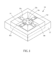
- a MEMS sensor denoted by numeral reference 10 and provided according to a first preferred embodiment of the present invention, is realized as a piezo-resistive type MEMS sensor capable of sensing three-axis acceleration and an absolute pressure.
- a MEMS sensor denoted by numeral reference 10 and provided according to a first preferred embodiment of the present invention, is realized as a piezo-resistive type MEMS sensor capable of sensing three-axis acceleration and an absolute pressure.
- the technical feature of the present invention can be applied on various MEMS sensors containing a moveable sensing element, including but not limited to the aforesaid one.
- the MEMS sensor 10 comprises mainly a frame 12, a proof mass 14 and four flexible bridges 16a to 16d integrally connected between the frame 12 and the proof mass 14 in such a way that the proof mass 14 is suspended inside the frame 12.
- the proof mass 14 is provided with a pressure sensing diaphragm 14a at a top surface thereof, and a sealed chamber 14b beneath the pressure sensing diaphragm 14a.
- the MEMS sensor 10 is a two-layered construction including a bottom layer 20 and a top layer 22 bonded on the bottom layer 20.
- a bottom layer 20 and a top layer 22 bonded on the bottom layer 20.
- Four sides of the bottom and top layers 20 and 22 form the hollow rectangular frame 12 of the MEMS sensor 10.
- the method of manufacturing the MEMS sensor it will be described in the following paragraphs.
- the top layer 22 has the aforesaid flexible bridges 16a to 16d and a rectangular center portion 22a on which the rectangular pressure sensing diaphragm 14a is defined.
- the four flexible bridges 16a to 16d each have an end integrally connected with a middle of one of four sides of the frame of the top layer 22, and the other end integrally connected with a middle of one of the four sides of the center portion 22a of the top layer 22. More specifically speaking, the four flexible bridges 16a to 16d can be divided into a first pair of bridges 16a and 16b, and a second pair of bridges 16c and 16d.
- the first pair of bridges 16a and 16b are linearly arranged on two opposite sides of the center portion 22a of the top layer 22, and the second pair of bridges 16c and 16d are linearly arranged on the other two opposite sides of the center portion 22a of the top layer 22 in such a way that the direction along which the first pair of bridges 16a and 16b extend is orthogonal to the direction along which the second pair of bridges 16e and 16d extend.
- the bottom layer 20 further comprises a center portion 20a corresponding in configuration to the center portion 22a of the top layer 22, such that the center portion 22a of the top layer 22 and the center portion 20a of the bottom layer 20 together form the above-mentioned proof mass 14.
- the center portion 20a of the bottom layer 20 is provided with a recess 20b, such that the above-mentioned sealed chamber 14b can be formed in between the pressure sensing diaphragm 14a of the center portion 22a of the top layer 22 and the center portion 20a of the bottom layer 20.
- the mechanical construction of the MEMS sensor 10 has been detailedly described in the foregoing paragraphs, and the electronic part of the MEMS sensor 10 for enabling three-axis acceleration and pressure measurement will be recited hereunder.
- a plurality of piezoresistances that can form three Wheatstone bridges for measuring accelerations in X-axis, Y-axis and Z-axis directions are implanted on the top surfaces of the flexible bridges 16a to 16d, and a plurality of piezoresistances that can form a Wheatstone bridge for measuring pressure are implanted on the top surface of the pressure sensing diaphragm 14a.
- a first set of four resistances R Y1 to R Y4 are arranged on the first pair of bridges 16a and 16b
- a second set of four resistances R X1 to R X4 and a third set of four resistances R Z1 to R Z4 are arranged on the second pair of bridges 16c and 16d
- a set of four resistances R P1 to R P4 are arranged on the pressure sensing diaphragm 14a. Since the structure and operation principle of the accelerometer of this kind are well-known to a person skilled in the arts including but not limited to US patent No. 4,905,523 and using piezoresistances to measure pressure is also a well-known prior art, a detailed description thereof needs not to be recited hereinafter.
- the MEMS sensor 10 can be served as an accelerometer, and in addition, the MEMS sensor can also be served as a pressure sensor thanks to the pressure sensing diaphragm, the sealed chamber and the pressure measuring resistances provided in the proof mass. Further, since the pressure sensing elements are integrated with the proof mass which is the moveable sensing element provided in a conventional accelerometer, the MEMS sensor that is capable of sensing acceleration and pressure and provided by the present invention can have a small size equal to the size of the conventional accelerometer.
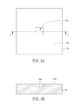
- the first step is to form a recess 30b on the top surface 30a of a silicon wafer 30 (hereinafter referred to as "the first wafer") by etching.
- the first wafer 30 may have a thickness of about 400 ⁇ m, and the recess 30b may have an area of about 500 ⁇ m by 500 ⁇ m, and a depth of about 1.0-50 ⁇ m.
- an n-type Si wafer 32 (hereinafter referred to as "the second wafer") is bonded on the top surface 30a of the first wafer 30.
- the second wafer For the way of bonding the two wafers, a fusion bonding or other appropriate way can be used.
- the second wafer 32 is thinned to about 5-10 ⁇ m, such that the portion of the second wafer 32, which corresponds in location and shape to the recess 30b, becomes the pressure sensing diaphragm 14a, and the sealed chamber 14b is formed in between the pressure sensing diaphragm 14a and the recess 30b.
- the crosssection of the sealed chamber 14b i.e. the shape of the diaphragm 14a, is not limited to square. Circle or other appropriate shape can be used.
- any suitable thinning technology including but not limited to mechanical grinding, chemical-mechanical polishing and wet chemical etching, can be used to thin the second wafer 32.
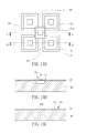
- FIGS. 7A and 7B show that resistances R X1 to R X4 , R Y1 to R Y4 , R Z1 to R Z4 and R P1 , to R P4 are implanted on predetermined locations of the second wafer 32.
- the detailed description about the way of forming the resistances can be found in US Patent No. 4,905,523 .
- the next step in the process is to form four openings 32a on the second wafer 32 by etching, as shown in FIGS. 8A and 8B .
- These openings 32a are equiangularly spaced around the centre portion of the second wafer 32.
- these openings 32a penetrate through the top and bottom surfaces of the second wafer 32 and have a predetermined configuration in such a way that four bridges 16a to 16d and a center portion 22a integrally connected with the bridges 16a to 16d are formed on the second wafer 32.
- a backside etching is carried out to remove the portions of the first wafer 30 that correspond in location and shape to the openings 32a so as to obtain the resistive-type MEMS sensor 10 of the first preferred embodiment of the present invention, which is capable of measuring acceleration and pressure.
- the first wafer 30 becomes eventually the bottom layer 20 of the MEMS sensor 10 and the second wafer 32 becomes the top layer 22 of the MEMS sensor 10.
- the bridges 16a to 16d have a thickness equal to the thickness of the pressure sensing diaphragm 14a, such that the bridges 16a to 16d and the pressure sensing diaphragm 14a have a same sensitivity of deformation.
- the thicknesses of the bridges and the pressure sensing diaphragm can be designed to be different, such that the bridges can have a sensitivity different from that of the diaphragm subject to the practical need. For example, as shown in FIG.
- the bottom surface of the center portion of the top layer 22 is provided by etching with a recess in alignment with the recess of the center portion of the bottom layer 20 such that the recesses of the center portions of the top and bottom layers 22 and 20 form the sealed chamber 14b of the proof mass 14 and the bridges 16c and 16d have a thickness greater than that of the diaphragm 14a.
- FIG. 11 shows an alternate form of the MEMS sensor, in which the thickness of the bridges 16c and 16d is smaller than that of the diaphragm 14a.
- the technical feature disclosed in the present invention can not only be applied on the above-mentioned piezo-resistive type accelerometer but also any kind of MEMS sensors having a moveable sensing element, e.g. a capacity type MEMS sensor capable of measuring acceleration and pressure as shown in FIG. 18 .
- a capacity type MEMS sensor capable of measuring acceleration and pressure as shown in FIG. 18 .
- the fabrication of the capacity type MEMS sensor in accordance a second preferred embodiment of the present invention will be described hereunder in accompaniment with FIGS. 12-18 .
- a sputtering process is carried out to form aluminum capacity electrodes C 1 to C 6 for measuring acceleration and pressure on the predetermined locations of the top surface of the second wafer 32, as shown in FIGS. 12A to 12C .
- the next step in the process is to form four openings 32a on the second wafer 32 by etching. As shown in FIGS. 13A to 13C . these openings 32a are equiangularly spaced around the center portion of the second wafer 32, penetrate through the top and bottom surfaces of the second wafer 32 and have a predetermined configuration in such a way that four bridges 16a to 16d, a rectangular center portion 22a integrally connected with the bridges 16a to 16d, and an ambient portion 32c containing four areas surrounded respectively by the four openings 32a are formed on the second wafer 32. It can be seen from the drawings that one capacity electrode is deposited on each of the areas of the ambient portion. The four areas of the ambient portion 32c of the second wafer 32 are integrally connected with and equiangularly spaced around the center portion 22a of the second wafer 32.
- a backside etching is carried out to remove the portions of the first wafer 30 that correspond in location and shape to the openings 32a of the second wafer 32 so as to obtain a main structure of capacity-type MEMS sensor of the second preferred embodiment of the present invention, which is capable of measuring acceleration and pressure.
- the first wafer 30 becomes eventually the bottom layer 20 of the MEMS sensor and the second wafer 32 becomes the top layer 22 of the MEMS sensor.
- the bottom layer 20 has a center portion 20a corresponding to the center portion 22a of the top layer 22, and an ambient portion 30c corresponding to the ambient portion 32c of the top layer 22 such that the center portions 20a and 22a and the ambient portions 30c and 32c of the bottom and top layers 20 and 22 form the proof mass and the sealed chamber 14b is formed in between the diaphragm 14a of the center portion 22a of the top layer 22 and the center portion 20a of the bottom layer 20.
- FIGS. 15 and 16 show a third wafer 40, on the bottom surface of which is provided with a ground electrode GND by sputtering, chemical vapor deposition or other suitable technology.
- the third wafer 40 is bonded on the top surface of the second wafer 32 by adhesive 42 such that the third wafer 40 can be served as a protective cap connected on the top layer 22 of the MEMS sensor.
- the third wafer 40 is bonded on the second wafer 32 in such a way that the ground electrode GND spacedly faces the capacity electrodes C 1 to C 6 so as to form six capacities therebetween.
- a pressure measuring capacity set and three capacity sets for measuring X-, Y- and Z-axis accelerations can be formed. It will be appreciated that the positions where the capacity electrodes are formed are not limited to the design disclosed in this preferred embodiment. Any suitable layout of the capacity electrodes that can achieve the acceleration and pressure measurement can be used in cooperation with the technical feature of the present invention.
- the MEMS sensor of the present invention is characterized in that the sealed chamber and the pressure sensing diaphragm for measuring pressure are integrated into the proof mass for measuring acceleration such that the MEMS sensor provided by the present invention is capable of measuring acceleration and pressure simultaneously.
- the MEMS sensor of the present invention has the advantages of low cost and small size.
Landscapes
- Physics & Mathematics (AREA)
- General Physics & Mathematics (AREA)
- Engineering & Computer Science (AREA)
- Chemical & Material Sciences (AREA)
- Analytical Chemistry (AREA)
- Manufacturing & Machinery (AREA)
- Microelectronics & Electronic Packaging (AREA)
- Pressure Sensors (AREA)
- Measuring Fluid Pressure (AREA)
Applications Claiming Priority (1)
| Application Number | Priority Date | Filing Date | Title |
|---|---|---|---|
| TW099130544A TWI414478B (zh) | 2010-09-09 | 2010-09-09 | 可同時量測加速度及壓力之微機電感測器 |
Publications (2)
| Publication Number | Publication Date |
|---|---|
| EP2431722A2 true EP2431722A2 (fr) | 2012-03-21 |
| EP2431722A3 EP2431722A3 (fr) | 2015-11-11 |
Family
ID=45554927
Family Applications (1)
| Application Number | Title | Priority Date | Filing Date |
|---|---|---|---|
| EP10189638.9A Withdrawn EP2431722A3 (fr) | 2010-09-09 | 2010-11-02 | Capteur MEMS capable de détecter l'accélération et la pression |
Country Status (3)
| Country | Link |
|---|---|
| US (1) | US8468888B2 (fr) |
| EP (1) | EP2431722A3 (fr) |
| TW (1) | TWI414478B (fr) |
Cited By (2)
| Publication number | Priority date | Publication date | Assignee | Title |
|---|---|---|---|---|
| TWI513981B (zh) * | 2014-11-13 | 2015-12-21 | Ind Tech Res Inst | 具多重氣密空腔的微機電裝置及其製作方法 |
| CN108370474A (zh) * | 2015-12-18 | 2018-08-03 | 美商楼氏电子有限公司 | 声感测设备及其制造方法 |
Families Citing this family (30)
| Publication number | Priority date | Publication date | Assignee | Title |
|---|---|---|---|---|
| DE102011076393A1 (de) * | 2011-05-24 | 2012-11-29 | Robert Bosch Gmbh | Mikromechanischer Drehbeschleunigungssensor und Verfahren zur Messung einer Drehbeschleunigung |
| US9323010B2 (en) | 2012-01-10 | 2016-04-26 | Invensas Corporation | Structures formed using monocrystalline silicon and/or other materials for optical and other applications |
| US8757897B2 (en) | 2012-01-10 | 2014-06-24 | Invensas Corporation | Optical interposer |
| FI124794B (fi) * | 2012-06-29 | 2015-01-30 | Murata Manufacturing Co | Parannettu resonaattori |
| US9611139B2 (en) | 2012-06-29 | 2017-04-04 | Murata Manufacturing Co., Ltd. | Resonator |
| US9606191B2 (en) * | 2013-03-15 | 2017-03-28 | Invensense, Inc. | Magnetometer using magnetic materials on accelerometer |
| US9239340B2 (en) * | 2013-12-13 | 2016-01-19 | Intel Corporation | Optomechanical sensor for accelerometry and gyroscopy |
| JP6258977B2 (ja) * | 2014-01-28 | 2018-01-10 | 京セラ株式会社 | センサおよびその製造方法 |
| US9581614B2 (en) | 2014-06-02 | 2017-02-28 | Meggit (Orange County), Inc. | High-output MEMS accelerometer |
| US9625486B2 (en) | 2014-07-17 | 2017-04-18 | Meggitt (Orange County), Inc. | MEMS accelerometer |
| US10466119B2 (en) | 2015-06-10 | 2019-11-05 | Nextinput, Inc. | Ruggedized wafer level MEMS force sensor with a tolerance trench |
| TW201728905A (zh) * | 2016-02-03 | 2017-08-16 | 智動全球股份有限公司 | 加速度計 |
| JP2017187447A (ja) * | 2016-04-08 | 2017-10-12 | アルプス電気株式会社 | センサ装置 |
| US11243125B2 (en) | 2017-02-09 | 2022-02-08 | Nextinput, Inc. | Integrated piezoresistive and piezoelectric fusion force sensor |
| EP4701393A2 (fr) | 2017-02-09 | 2026-02-25 | Nextinput, Inc. | Capteurs de force numériques intégrés et procédés de fabrication associés |
| DE102017203384B3 (de) | 2017-03-02 | 2018-01-18 | Robert Bosch Gmbh | Mikromechanischer Drucksensor |
| DE102017208048B3 (de) * | 2017-05-12 | 2018-09-27 | Robert Bosch Gmbh | Mikromechanischer Drucksensor |
| EP3655740A4 (fr) | 2017-07-19 | 2021-07-14 | Nextinput, Inc. | Empilement de transfert de contrainte dans un capteur de force mems |
| WO2019023309A1 (fr) | 2017-07-25 | 2019-01-31 | Nextinput, Inc. | Capteur de force et d'empreintes digitales intégré |
| US11243126B2 (en) | 2017-07-27 | 2022-02-08 | Nextinput, Inc. | Wafer bonded piezoresistive and piezoelectric force sensor and related methods of manufacture |
| US11579028B2 (en) | 2017-10-17 | 2023-02-14 | Nextinput, Inc. | Temperature coefficient of offset compensation for force sensor and strain gauge |
| US11385108B2 (en) | 2017-11-02 | 2022-07-12 | Nextinput, Inc. | Sealed force sensor with etch stop layer |
| WO2019099821A1 (fr) | 2017-11-16 | 2019-05-23 | Nextinput, Inc. | Atténuateur de force pour capteur de force |
| US11186481B2 (en) | 2017-11-30 | 2021-11-30 | Taiwan Semiconductor Manufacturing Company, Ltd. | Sensor device and manufacturing method thereof |
| CN108627287A (zh) * | 2018-06-06 | 2018-10-09 | 上海天沐自动化仪表有限公司 | 一体化硅压阻式传感器芯片 |
| CN109341932B (zh) * | 2018-11-09 | 2024-02-02 | 青岛歌尔微电子研究院有限公司 | 一种压力传感器芯片及其制造方法 |
| US10962427B2 (en) | 2019-01-10 | 2021-03-30 | Nextinput, Inc. | Slotted MEMS force sensor |
| CN110545511B (zh) * | 2019-08-16 | 2021-05-07 | 瑞声声学科技(深圳)有限公司 | 压电式mems麦克风 |
| JP7080372B1 (ja) * | 2021-03-30 | 2022-06-03 | 三菱電機株式会社 | 半導体圧力センサ及び圧力センサ装置 |
| CN117836598A (zh) * | 2021-08-31 | 2024-04-05 | 株式会社村田制作所 | 压力传感器元件及压力传感器 |
Citations (1)
| Publication number | Priority date | Publication date | Assignee | Title |
|---|---|---|---|---|
| US4905523A (en) | 1987-04-24 | 1990-03-06 | Wacoh Corporation | Force detector and moment detector using resistance element |
Family Cites Families (6)
| Publication number | Priority date | Publication date | Assignee | Title |
|---|---|---|---|---|
| JP2003232803A (ja) * | 2002-02-12 | 2003-08-22 | Hitachi Metals Ltd | 半導体型加速度センサ |
| WO2005062060A1 (fr) * | 2003-12-24 | 2005-07-07 | Hitachi Metals, Ltd. | Capteur d'acceleration a 3 axes de type a semi-conducteur |
| JP2006201041A (ja) * | 2005-01-20 | 2006-08-03 | Oki Electric Ind Co Ltd | 加速度センサ |
| JP2006349613A (ja) * | 2005-06-20 | 2006-12-28 | Micro Precision Kk | 容量検出型加速度センサ |
| DE102005055473A1 (de) * | 2005-11-22 | 2007-05-24 | Robert Bosch Gmbh | Mikromechanische Vorrichtung und Verfahren zur Herstellung einer mikromechanischen Vorrichtung |
| US7508040B2 (en) * | 2006-06-05 | 2009-03-24 | Hewlett-Packard Development Company, L.P. | Micro electrical mechanical systems pressure sensor |
-
2010
- 2010-09-09 TW TW099130544A patent/TWI414478B/zh not_active IP Right Cessation
- 2010-11-02 EP EP10189638.9A patent/EP2431722A3/fr not_active Withdrawn
- 2010-11-22 US US12/951,738 patent/US8468888B2/en not_active Expired - Fee Related
Patent Citations (1)
| Publication number | Priority date | Publication date | Assignee | Title |
|---|---|---|---|---|
| US4905523A (en) | 1987-04-24 | 1990-03-06 | Wacoh Corporation | Force detector and moment detector using resistance element |
Cited By (4)
| Publication number | Priority date | Publication date | Assignee | Title |
|---|---|---|---|---|
| TWI513981B (zh) * | 2014-11-13 | 2015-12-21 | Ind Tech Res Inst | 具多重氣密空腔的微機電裝置及其製作方法 |
| US9586815B2 (en) | 2014-11-13 | 2017-03-07 | Industrial Technology Research Institute | Micro-electromechanical apparatus with multiple chambers and method for manufacturing the same |
| CN108370474A (zh) * | 2015-12-18 | 2018-08-03 | 美商楼氏电子有限公司 | 声感测设备及其制造方法 |
| CN108370474B (zh) * | 2015-12-18 | 2019-08-09 | 美商楼氏电子有限公司 | 声感测设备及麦克风 |
Also Published As
| Publication number | Publication date |
|---|---|
| EP2431722A3 (fr) | 2015-11-11 |
| TW201215558A (en) | 2012-04-16 |
| US20120060605A1 (en) | 2012-03-15 |
| TWI414478B (zh) | 2013-11-11 |
| US8468888B2 (en) | 2013-06-25 |
Similar Documents
| Publication | Publication Date | Title |
|---|---|---|
| US8468888B2 (en) | MEMS sensor capable of sensing acceleration and pressure | |
| KR101145999B1 (ko) | 변환기 및 변환기 제조 방법 | |
| EP2411817B1 (fr) | Transducteur mems d'accélération intégré verticalement | |
| US7368312B1 (en) | MEMS sensor suite on a chip | |
| US10371714B2 (en) | Teeter-totter type MEMS accelerometer with electrodes on circuit wafer | |
| US8925384B2 (en) | MEMS sensor with stress isolation and method of fabrication | |
| US20130205899A1 (en) | Combo Transducer and Combo Transducer Package | |
| US20180074090A1 (en) | Multiple degree of freedom mems sensor chip and method for fabricating the same | |
| US10371715B2 (en) | MEMS accelerometer with proof masses moving in an anti-phase direction | |
| EP2284545B1 (fr) | Masses sismiques coplanaires permettant de détecter une accélération le long de trois axes | |
| US20110067495A1 (en) | Micromachined accelerometer with monolithic electrodes and method of making the same | |
| US20220144624A1 (en) | Electrode layer partitioning | |
| JP2005249454A (ja) | 容量型加速度センサ | |
| WO2015042702A1 (fr) | Dispositif mems comprenant une structure de support et méthode de fabrication | |
| CN102408089A (zh) | 可同时量测加速度及压力的微机电传感器 | |
| US20160341759A1 (en) | Sensor and method of manufacturing same | |
| JP5292600B2 (ja) | 加速度センサ | |
| EP1365211B1 (fr) | Gyroscope intégré fabriqué en matière semi-conductrice avec au moins un axe sensible dans le plan du capteur | |
| JP2010107240A (ja) | 1軸加速度センサ及びそれを用いた3軸加速度センサ | |
| US20150007657A1 (en) | Inertial sensor and method of manufacturing the same | |
| KR20140028991A (ko) | 중첩형 관성 센서 및 그 제어 방법 |
Legal Events
| Date | Code | Title | Description |
|---|---|---|---|
| PUAI | Public reference made under article 153(3) epc to a published international application that has entered the european phase |
Free format text: ORIGINAL CODE: 0009012 |
|
| AK | Designated contracting states |
Kind code of ref document: A2 Designated state(s): AL AT BE BG CH CY CZ DE DK EE ES FI FR GB GR HR HU IE IS IT LI LT LU LV MC MK MT NL NO PL PT RO RS SE SI SK SM TR |
|
| AX | Request for extension of the european patent |
Extension state: BA ME |
|
| PUAL | Search report despatched |
Free format text: ORIGINAL CODE: 0009013 |
|
| AK | Designated contracting states |
Kind code of ref document: A3 Designated state(s): AL AT BE BG CH CY CZ DE DK EE ES FI FR GB GR HR HU IE IS IT LI LT LU LV MC MK MT NL NO PL PT RO RS SE SI SK SM TR |
|
| AX | Request for extension of the european patent |
Extension state: BA ME |
|
| RIC1 | Information provided on ipc code assigned before grant |
Ipc: G01L 9/00 20060101AFI20151006BHEP Ipc: G01P 15/12 20060101ALI20151006BHEP Ipc: G01L 19/00 20060101ALI20151006BHEP Ipc: G01P 15/125 20060101ALI20151006BHEP Ipc: G01P 15/08 20060101ALI20151006BHEP |
|
| STAA | Information on the status of an ep patent application or granted ep patent |
Free format text: STATUS: THE APPLICATION IS DEEMED TO BE WITHDRAWN |
|
| 18D | Application deemed to be withdrawn |
Effective date: 20160512 |