EP2432242A2 - Appareil d'affichage d'images, panneau d'affichage - Google Patents
Appareil d'affichage d'images, panneau d'affichage Download PDFInfo
- Publication number
- EP2432242A2 EP2432242A2 EP11181200A EP11181200A EP2432242A2 EP 2432242 A2 EP2432242 A2 EP 2432242A2 EP 11181200 A EP11181200 A EP 11181200A EP 11181200 A EP11181200 A EP 11181200A EP 2432242 A2 EP2432242 A2 EP 2432242A2
- Authority
- EP
- European Patent Office
- Prior art keywords
- pixel
- aperture
- displaying
- region
- observing point
- Prior art date
- Legal status (The legal status is an assumption and is not a legal conclusion. Google has not performed a legal analysis and makes no representation as to the accuracy of the status listed.)
- Withdrawn
Links
- 230000001154 acute effect Effects 0.000 claims abstract description 34
- 238000000926 separation method Methods 0.000 claims description 61
- 230000003287 optical effect Effects 0.000 claims description 60
- 239000011159 matrix material Substances 0.000 claims description 23
- 238000009826 distribution Methods 0.000 abstract description 51
- 239000004973 liquid crystal related substance Substances 0.000 description 60
- 230000000694 effects Effects 0.000 description 49
- 239000011295 pitch Substances 0.000 description 34
- 239000000758 substrate Substances 0.000 description 32
- 230000008859 change Effects 0.000 description 15
- 238000000034 method Methods 0.000 description 15
- 230000005684 electric field Effects 0.000 description 13
- 239000003086 colorant Substances 0.000 description 8
- 238000012545 processing Methods 0.000 description 8
- 230000009467 reduction Effects 0.000 description 8
- 230000004888 barrier function Effects 0.000 description 7
- 230000007423 decrease Effects 0.000 description 7
- 230000006866 deterioration Effects 0.000 description 7
- 238000002834 transmittance Methods 0.000 description 7
- 230000006872 improvement Effects 0.000 description 6
- 238000004519 manufacturing process Methods 0.000 description 6
- 239000003795 chemical substances by application Substances 0.000 description 5
- 230000002411 adverse Effects 0.000 description 4
- 239000011521 glass Substances 0.000 description 4
- 230000015572 biosynthetic process Effects 0.000 description 3
- 239000003990 capacitor Substances 0.000 description 3
- 230000002542 deteriorative effect Effects 0.000 description 3
- 239000000463 material Substances 0.000 description 3
- 238000005259 measurement Methods 0.000 description 3
- 239000004065 semiconductor Substances 0.000 description 3
- 239000010409 thin film Substances 0.000 description 3
- XLOMVQKBTHCTTD-UHFFFAOYSA-N Zinc monoxide Chemical compound [Zn]=O XLOMVQKBTHCTTD-UHFFFAOYSA-N 0.000 description 2
- 208000003464 asthenopia Diseases 0.000 description 2
- 230000003190 augmentative effect Effects 0.000 description 2
- 229910052799 carbon Inorganic materials 0.000 description 2
- 239000012141 concentrate Substances 0.000 description 2
- 238000005401 electroluminescence Methods 0.000 description 2
- 238000005516 engineering process Methods 0.000 description 2
- 210000003811 finger Anatomy 0.000 description 2
- 210000003128 head Anatomy 0.000 description 2
- 238000003754 machining Methods 0.000 description 2
- 229910052751 metal Inorganic materials 0.000 description 2
- 239000002184 metal Substances 0.000 description 2
- 239000002245 particle Substances 0.000 description 2
- 229910021420 polycrystalline silicon Inorganic materials 0.000 description 2
- 229920005591 polysilicon Polymers 0.000 description 2
- OKTJSMMVPCPJKN-UHFFFAOYSA-N Carbon Chemical compound [C] OKTJSMMVPCPJKN-UHFFFAOYSA-N 0.000 description 1
- 230000001464 adherent effect Effects 0.000 description 1
- 229910021417 amorphous silicon Inorganic materials 0.000 description 1
- 239000002131 composite material Substances 0.000 description 1
- 230000003247 decreasing effect Effects 0.000 description 1
- 238000013461 design Methods 0.000 description 1
- 230000003292 diminished effect Effects 0.000 description 1
- 230000003467 diminishing effect Effects 0.000 description 1
- 239000010408 film Substances 0.000 description 1
- 238000003384 imaging method Methods 0.000 description 1
- 238000010348 incorporation Methods 0.000 description 1
- 239000007788 liquid Substances 0.000 description 1
- 150000002739 metals Chemical class 0.000 description 1
- 238000012986 modification Methods 0.000 description 1
- 230000004048 modification Effects 0.000 description 1
- 229910021421 monocrystalline silicon Inorganic materials 0.000 description 1
- 238000000465 moulding Methods 0.000 description 1
- 239000011368 organic material Substances 0.000 description 1
- SLIUAWYAILUBJU-UHFFFAOYSA-N pentacene Chemical compound C1=CC=CC2=CC3=CC4=CC5=CC=CC=C5C=C4C=C3C=C21 SLIUAWYAILUBJU-UHFFFAOYSA-N 0.000 description 1
- 238000000206 photolithography Methods 0.000 description 1
- 238000007517 polishing process Methods 0.000 description 1
- 230000008569 process Effects 0.000 description 1
- 230000000630 rising effect Effects 0.000 description 1
- 230000002195 synergetic effect Effects 0.000 description 1
- 210000003813 thumb Anatomy 0.000 description 1
- 230000007704 transition Effects 0.000 description 1
- 238000007514 turning Methods 0.000 description 1
- 239000011787 zinc oxide Substances 0.000 description 1
- -1 zinc oxide Chemical class 0.000 description 1
Images


Classifications
-
- G—PHYSICS
- G02—OPTICS
- G02B—OPTICAL ELEMENTS, SYSTEMS OR APPARATUS
- G02B30/00—Optical systems or apparatus for producing three-dimensional [3D] effects, e.g. stereoscopic images
- G02B30/20—Optical systems or apparatus for producing three-dimensional [3D] effects, e.g. stereoscopic images by providing first and second parallax images to an observer's left and right eyes
- G02B30/26—Optical systems or apparatus for producing three-dimensional [3D] effects, e.g. stereoscopic images by providing first and second parallax images to an observer's left and right eyes of the autostereoscopic type
- G02B30/30—Optical systems or apparatus for producing three-dimensional [3D] effects, e.g. stereoscopic images by providing first and second parallax images to an observer's left and right eyes of the autostereoscopic type involving parallax barriers
- G02B30/31—Optical systems or apparatus for producing three-dimensional [3D] effects, e.g. stereoscopic images by providing first and second parallax images to an observer's left and right eyes of the autostereoscopic type involving parallax barriers involving active parallax barriers
-
- G—PHYSICS
- G02—OPTICS
- G02B—OPTICAL ELEMENTS, SYSTEMS OR APPARATUS
- G02B30/00—Optical systems or apparatus for producing three-dimensional [3D] effects, e.g. stereoscopic images
-
- G—PHYSICS
- G02—OPTICS
- G02B—OPTICAL ELEMENTS, SYSTEMS OR APPARATUS
- G02B30/00—Optical systems or apparatus for producing three-dimensional [3D] effects, e.g. stereoscopic images
- G02B30/20—Optical systems or apparatus for producing three-dimensional [3D] effects, e.g. stereoscopic images by providing first and second parallax images to an observer's left and right eyes
- G02B30/26—Optical systems or apparatus for producing three-dimensional [3D] effects, e.g. stereoscopic images by providing first and second parallax images to an observer's left and right eyes of the autostereoscopic type
- G02B30/27—Optical systems or apparatus for producing three-dimensional [3D] effects, e.g. stereoscopic images by providing first and second parallax images to an observer's left and right eyes of the autostereoscopic type involving lenticular arrays
-
- H—ELECTRICITY
- H04—ELECTRIC COMMUNICATION TECHNIQUE
- H04N—PICTORIAL COMMUNICATION, e.g. TELEVISION
- H04N13/00—Stereoscopic video systems; Multi-view video systems; Details thereof
-
- H—ELECTRICITY
- H04—ELECTRIC COMMUNICATION TECHNIQUE
- H04N—PICTORIAL COMMUNICATION, e.g. TELEVISION
- H04N13/00—Stereoscopic video systems; Multi-view video systems; Details thereof
- H04N13/30—Image reproducers
- H04N13/302—Image reproducers for viewing without the aid of special glasses, i.e. using autostereoscopic displays
- H04N13/305—Image reproducers for viewing without the aid of special glasses, i.e. using autostereoscopic displays using lenticular lenses, e.g. arrangements of cylindrical lenses
Definitions
- the present invention relates to an image display apparatus and display panel for displaying different images intended for multiple observing points and particularly to a display panel displaying three-dimensional images in higher quality.
- image display apparatuses As cell-phones and information terminals have been advanced, image display apparatuses become smaller and finer. On the other hand, as new value-added image display apparatuses, attention has been drawn to image display apparatuses allowing the observer to view different images depending on the observing point, namely image display apparatuses making different images visible at multiple observing points, and to three-dimensional image display apparatuses presenting different images as parallax images and allowing the observer to view a three-dimensional image.
- Techniques of providing different images to multiple observing points consist of merging image data for different observing points and displaying them on a display panel, separating the displayed composite image by an optical separation means such as a lens and a barrier having slits (a screen), and providing the images to individual observing points.
- images are separated by an optical means such as a barrier having slits and a lens so as to limit each image to a direction of observing point.
- a parallax barrier consisting of a barrier having many slits in a stripe pattern or a lenticular lens consisting of an array of cylindrical lenses having lens effect in one directional is generally used as the image separation means.
- a three-dimensional image display apparatus having an optical image separation means is suitable for installing in terminal devices such as cell-phones because it does not require wearing special glasses and eliminates annoyance of wearing glasses.
- Cell-phones carrying a three-dimensional display apparatus consisting of a liquid crystal panel and a parallax barrier are already commercialized (for example, see NIKKEI Electronics, January 6, 2003, No. 838 (Non-Patent Literature 1, hereafter), pp 26-27 ).
- the above technology namely a three-dimensional image display apparatus providing different images to multiple observing points using an optical separation means sometimes causes the observer to see a dark boundary between images when he/she shifts the observing point and the observed image is switched.
- This phenomenon occurs when a non-display region between pixels for different observing points (a shielding part generally called a black matrix in a liquid crystal panel) is viewed.
- This phenomenon accompanying shift of the observing point of the observer does not occur with a general three-dimensional display apparatus without an optical separation means. Therefore, the observer experiences discomfort or senses deterioration in the display quality from the above phenomenon occurring with a multi-viewpoint three-dimensional display apparatus or three-dimensional display apparatus with an optical separation means.
- the 3D moire is a periodically appearing uneven luminance (sometimes referred to as uneven color) caused by displaying different images in different angular directions. Furthermore, the 3D moire is luminance angular fluctuation and large luminance angular fluctuation has adverse effect on three-dimensional observation.
- FIG. 37 is a plane view showing the display panel of the display apparatus disclosed in Patent Literature 1.
- the shielding part the wire 1070 and shielding part 1076
- aperture are provided nearly at a fixed ratio in a cross-section of the display panel in the vertical direction 1011 perpendicular to the direction of the array of cylindrical lenses 1003a.
- the shielding part viewed is nearly at the fixed ratio. In other words, it does not happen to the observer to see only the shielding part in a specific direction or to see a darker display. Then, deterioration in the display quality caused by the shielding region is prevented.
- FIG. 38 is a schematic illustration showing pixels of the three-dimensional display apparatus disclosed in the Patent Literature 2.
- FIG. 38 (A) is a plane view showing the pixel arrangement of the three-dimensional display apparatus disclosed in the Patent Literature 2 and
- FIG. 38 (B) is an enlarged view of a pixel thereof.
- the total vertical dimension of horizontally adj acent pixels is constant at any position in the horizontal direction in the overlapping region.
- the total dimension is equal to the vertical dimension of a rectangular region B. Therefore, horizontally continuous and substantially uniform luminance is provided and substantially constant luminance is maintained all over.
- FIG. 36 is an illustration schematically showing a prior art pixel structure disclosed in the Patent Literature 1 and 2.
- a display unit 4 consisting of a pair of a right-eye pixel 4R and a left-eye pixel 4L is shown.
- the aperture of each pixel has an isosceles trapezoid shape.
- a sub-pixel When the focus is on one of the minimum unit pixels (the right-eye pixel 4R or the left-eye pixel 4L) constituting the display unit 4, it is referred to as "a sub-pixel" without particular distinction.
- the display unit 4 comprises at least the right-eye pixel 4R and left-eye pixel 4L as two sub-pixels adjacent to each other in the X-axis direction.
- the three-dimensional image display apparatus comprises a cylindrical lens 1003a as an optical means for separating light emerging from the apertures of sub-pixels into separated images in the X-axis direction.
- the image separation direction is defined as the X-axis direction and the direction perpendicular thereto is defined as the Y-axis direction.
- the term "vertical aperture” refers to the width of an aperture in the direction perpendicular to the image separation direction (which corresponds to the Y-axis in the case of FIG. 37 ).
- the smaller base is referred to as the upper base and the larger base is referred to as the lower base.
- the aperture of the right-eye pixel 4R and the aperture of the left-eye pixel 4L are provided next to each other in the X-axis direction. There is a region on their border where these apertures overlap with each other in the Y-axis direction. The region where these apertures overlap with each other is termed "the overlapping region" and the width of such a region in the X-axis direction is defined as an overlapping region width Xct1.
- the non-overlapping region a region in the center of the aperture where the aperture of the right-eye pixel 4R and the aperture of the left-eye pixel 4L do not overlap with each other is termed "the non-overlapping region” and the width of such a region in the X-axis direction is defined as a non-overlapping region width X1.
- the pitch Xdot of sub-pixels in the X-axis direction is equal to the sum of the overlapping region width Xctl and non-overlapping region width X1.
- the aperture of a sub-pixel is in the shape of an isosceles trapezoid symmetric about a line b-b' parallel to the Y-axis and passing through the center of the sub-pixel and having upper and lower bases parallel to the X-axis.
- a shielding line having a finite width W is provided on the oblique sides of the trapezoid.
- the oblique side makes an angle ⁇ with respect to the Y-axis.
- the shielding line is termed "the oblique wire.”
- Points A and A' are the vertexes of the lower bases of the trapezoidal apertures of the sub-pixels.
- Points B and B' are the vertexes of the upper bases of the trapezoidal apertures of the sub-pixels.
- the points A and A' and points B and B' are inflexion points where the vertical aperture width of a sub-pixel starts to change in the X-axis direction.
- a point C is a point where a line parallel to the Y-axis and passing through the point B and the lower base of the trapezoidal aperture intersect and so is a point C' with regard to the point B'.
- the line connecting the points A and B and the line connecting the points A' and B' are parallel to each other. Then, the total of the vertical aperture widths of the right-eye pixel 4R and left-eye pixel 4L in the overlapping region is always constant in the X-axis direction. Furthermore, the points A and B' and points A' and B are situated on the same line parallel to the Y-axis, respectively, so that the vertical aperture width in the non-overlapping region and the total of the vertical aperture widths of the apertures of the right-eye pixel 4R and left-eye pixel 4L in the overlapping regions are equal. In this way, the vertical aperture width is constant from the overlapping region to the non-overlapping region and always constant throughout a sub-pixel in the X-axis direction.
- the display unit 4 has an oblique wire making an angle ⁇ with respect to the Y-axis and having a display wire width W.
- the sides of the oblique wire are connected to the lower bases of the trapezoidal apertures at the points A and A' and connected to the upper bases of the trapezoidal apertures at the points B and B'.
- the oblique wire is connected to a shielding part at the trapezoid upper base. This shielding part has a width Y2 in the Y-axis direction and provides a region where, for example, transistors and capacitors for operating the sub-pixel are formed.
- the total of the vertical aperture widths of adjacent sub-pixels is constant in the X-axis direction. Therefore, assuming that lights equal in luminance are emitted from the aperture region in the overlapping region and the aperture region in the non-overlapping region, the luminance is maintained constant at observation positions parallel to the X-axis. Then, there is no luminance angular fluctuation, in other words 3D moire is not visible to the observer.
- a triangular region formed by connecting the points A, B, and C and a triangular region formed by connecting the points A', B', and C' of the display unit 4 are right triangles and situated within the overlapping region width Xct1.
- This is a crosstalk region where lights emitted from the right-eye pixel 4R and left-eye pixel 4L overlap with each other.
- the prior art pixel structure has to form at least such a crosstalk region to have a constant vertical aperture width in the X-axis direction, thereby causing 3D crosstalk (the rate of a right-eye or left-eye image leaking into the other) upon three-dimensional display.
- 3D moire or “3D crosstalk” will be described in detail.
- periodically appearing uneven luminance (sometimes referred to as uneven color) caused by displaying different images in different angular directions, particularly luminance angular fluctuation is defined as “3D moire.”
- 3D moire the rate of a right-eye or left-eye image leaking into the other is defined as “3D crosstalk.”
- the moire fringes are interference fringes appearing depending on the periodicity or pitch of structures.
- the 3D moire is uneven luminance caused by the image-forming property of an image separation means. Therefore, the 3D moire is distinguished from the moire fringes in this specification.
- the 3D moire may not be a problem in some observation positions.
- large luminance angular fluctuation presumably has some adverse effect on three-dimensional observation. Therefore, it is desirable that the magnitude of luminance fluctuation is equal to or lower than a given value.
- the aperture ratio AP 3D crosstalk 3Dct, and 3D moire 3Dmoire are defined as follows. From the pixel shown, the aperture ratio AP can be defined by the following formula from the area ratio between the shielding part and aperture.
- 3D crosstalk contributes to a region as large as the sub-pixel pitch Xdot
- 3D crosstalk (3Dct) can be defined by the following formula from the area ratio between the aperture region and overlapping region.
- 3D moire can be defined by the following formula from the ratio between the vertical aperture width Y1 in the non-overlapping region and the total of the vertical aperture widths of the right-eye and left-eye pixels 4R and 4L in the overlapping region.
- the overlapping region width Xct1 is determined by the inclination ⁇ of the oblique wire and 3D crosstalk (3Dct) is significant as the angle ⁇ is increased.
- the display panel of a display apparatus is required to have a smaller pixel pitch in order to improve the fineness and have a higher so-called aperture ratio determined by the area ratio between the aperture and shielding part and contributing to the display luminance in order to improve the display luminance. This also applies to a three-dimensional display apparatus.
- a liquid crystal display apparatus undergoes increase in the shielding region, namely decrease in the aperture ratio, because of limitation accompanying higher fineness, having a problem that the display apparatus overall uses light less efficiently. In other words, improving the image quality by finer pixels leads to less efficient use of light. Therefore, it is an issue with a liquid crystal display apparatus to realize a finer image and realize a high quality and highly efficient image display apparatus.
- a three-dimensional display panel having two or more observing points as in the three-dimensional image display apparatuses disclosed in the Patent Literature 1 and 2 has multiple sub-pixels corresponding to the number of observing points in one pixel. Therefore, the area involved in wires and switching elements in one pixel is increased. Particularly, a finer pixel has a significantly decreased aperture ratio and therefore, improvement in the aperture ratio is an important issue.
- a finer pixel has to be designed with priority at least on the aperture ratio in order to ensure a desired transmittance.
- the wire angle ⁇ in the boundary region must be increased.
- the overlapping region width Xct1 is also increased, whereby 3D crosstalk becomes so significant that the visibility of thee-dimensional display is adversely affected.
- a sub-pixel becomes very small in the Y-axis direction depending on the number of colors.
- the spot diameter should be reduced to improve the separation performance of the lens in order to increase the region in which a three-dimensional image is comfortably observed.
- advanced lens processing techniques allow for application of lenses having a spot diameter in the order of several microns.
- the spot diameter is reduced, slight geometric change due to the processing accuracy of production process is augmented even in a pixel structure designed to have a nearly constant vertical aperture width in the image separation direction as in the prior art technology shown in FIG. 36 . Consequently, uneven luminance locally occurs, significantly deteriorating the image quality.
- a sub-pixel has an isosceles trapezoid aperture. It is obvious that the near parallelogram pixel structure disclosed in the Patent Literature 2 has the same problems.
- the present invention is invented in view of the above circumstances and an exemplary object of the present invention is to provide an image display apparatus and display panel having 3D crosstalk reduced and the aperture ratio improved while minimizing the influence of 3D moire so as to improve the three-dimensional display quality.
- the image display apparatus includes:
- the image display apparatus includes:
- the image display apparatus includes:
- the image display apparatus includes:
- the display panel according to a first exemplary aspect of the present invention is a display panel having a plurality of display units which are arranged in a matrix and include at least a pixel displaying a first observing point image and a pixel displaying a second observing point image, wherein:
- An exemplary object of the present invention is to provide an image display apparatus and display panel having the 3D crosstalk reduced and the aperture ratio improved while minimizing the influence of 3D moire asp as to improve the three-dimensional display quality.
- FIG. 1 is a plane view showing a pixel of the display panel according to this embodiment.
- a display panel 2 is a three-dimensional display panel of two observing points comprising pixels displaying a first observing point image and pixels displaying a second observing point image.
- the first observing point pixels are left-eye pixels 4L and the second observing point pixels are right-eye pixels 4R.
- a pair of a left-eye pixel 4L and a right-eye pixel 4R constitutes a display unit 4.
- a sub-pixel When the focus is on one of the minimum unit pixels constituting a display unit 4 (a left-eye pixel 4L or a right-eye pixel 4R), it is referred to as "a sub-pixel.”
- the sub-pixels are arranged in a matrix.
- a cylindrical lens 3a is a one-dimensional lens having a dome-shaped convex part.
- the cylindrical lens 3a extends or lengthens in the direction perpendicular to the array direction in the display plane.
- the cylindrical lens 3a has no lens effect in the extending direction; it has lens effect only in the array direction perpendicular thereto.
- FIG. 2 is a cross-sectional view showing the image display apparatus according to the present invention.
- An image display apparatus 1 is composed of a display panel 2 using liquid crystal molecules as an electrooptical element, a lenticular lens 3, and a backlight 15.
- the lenticular lens 3 is a lens array consisting of many cylindrical lenses 3a arranged in one dimension.
- the cylindrical lenses 3a have lens effect only in the array direction.
- the array direction of the cylindrical lenses 3a is equal to the direction the left-eye pixels 4L and right-eye pixels 4R are arranged alternately.
- a cylindrical lens 3a is situated in accordance with a display unit 4.
- the cylindrical lens 3a serves as a light beam separation means separating light of the left-eye pixel 4L and light of the right-eye pixel 4R into different directions. Then, the cylindrical lens 3a can separate an image displayed by the left-eye pixel 4L and an image displayed by the right-eye pixel 4R in different directions.
- the lenticular lens 3 is an optical member serving as an image separation means or an image sorting means.
- the cylindrical lens 3a has a focal point between the principal point or vertex of the cylindrical lens 3a and the pixel surface or the plane of the left-eye pixel 4L or right-eye pixel 4R.
- a XYX Cartesian coordinate system is defined as follows for convenience.
- the first direction from the right-eye pixel 4R to the left-eye pixel 4L is defined as the +X direction and the opposite direction is defined as the -X direction.
- the +X direction and -X direction are collectively termed the X-axis direction.
- the lengthwise direction of the cylindrical lens 3a is the second direction and defined as the Y-axis direction.
- the third direction perpendicular both to the X-axis direction and to the Y-axis direction is defined as the Z-axis direction.
- the direction from the plane of the left-eye pixel 4L or right-eye pixel 4R to the lenticular lens 3 is defined as the +Z direction and the opposite direction is defined as the -Z direction.
- the +Z direction extends forward or to the observer. The observer views the display panel 2 on the side facing in the +Z direction.
- the +Y direction is the direction a right-handed coordinate system is established. In other words, when the thumb of the right hand of a person is directed in the +X direction and the index finger is directed in the +Y direction, the middle finger is directed in the +Z direction.
- the cylindrical lenses 3a are arranged in the X-axis direction and the left-eye image and right-eye image are separated in the X-axis direction.
- the display units 4 are lined up in the Y-axis direction.
- the display units 4 and cylindrical lenses 3a are arranged at the same pitch in the X-axis direction.
- the cylindrical lenses 3a are each situated in accordance with a column of display units 4 arranged in the Y-axis direction.
- a line of sub-pixels in the X-axis is referred to as a row and a line of sub-pixels in the Y-axis is referred to as a column.
- a display unit 4 consists of a right-eye pixel 4R and a left-eye pixel 4L and a display unit 4' consists of a right-eye pixel 4R' and a left-eye pixel 4L'.
- one pixel consists of three display units.
- Each display unit 4 is colored in red, green, or blue.
- Red, green, and blue color filters extend in the X-axis direction and create a stripe pattern repeated in the Y-axis direction.
- the order of colors is not restricted to the above and red, green, and blue colors are combined in any order.
- one pixel can consist of a combination of three or more display units. In such a case, the colors are not restricted to the above and three or more colors can be used.
- a display panel 2 has a small space between a TFT (thin film transistor) substrate 2a and an opposite substrate 2b, in which a liquid crystal layer 5LC is provided.
- the TFT substrate 2a is provided on the side of the display panel 2 facing in the -Z direction and the opposite substrate 2b is provided on the side facing in the +Z direction.
- the lenticular lens 3 is provided on the side of the opposite substrate 2b facing further in the +Z direction.
- Polarizing plates 11 are applied to the side of the TFT substrate 2a facing in the +Z direction and to the side of the opposite substrate 2b facing in the -Z direction.
- the color filters and a shielding part 76 shown in FIG. 1 are provided to the opposite substrate 2b. However, this is not restrictive.
- a shielding layer provided to the TFT substrate 2a is also included in the shielding part 76.
- the pixel structure of the image display apparatus 1 according to this embodiment will be described in detail with reference to FIG. 1 .
- the sub-pixels of the display panel 2 have a hexagonal aperture consisting of a combination of two trapezoids in a plane view. More specifically, the aperture shape is formed by providing a first trapezoid bilaterally symmetric about a line b-b' parallel to the Y-axis and passing through the center of the sub pixel and a second trapezoid having a lower base equal in length to the lower base of the first trapezoid with their lower bases in contact with each other.
- the bases of a trapezoid the larger base is referred to as the lower base and the smaller base is referred to as the upper base.
- the hexagonal shape can be considered to be substantially a nearly trapezoidal shape.
- a hexagonal sub-pixel is referred to as a nearly trapezoidal pixel.
- the larger base is referred to as the lower base and the smaller base is referred to as the upper base.
- a shielding part is provided around the nearly trapezoidal aperture.
- the above-described sub-pixel of the display panel 2 has a nearly trapezoidal aperture having upper and lower bases nearly parallel to the X-axis and two oblique sides oblique in directions different from the Y-axis direction, and nearly triangular shielding parts (for example, a triangle ADE) are provided at the acute angle parts of the nearly trapezoidal shape.
- nearly triangular shielding parts for example, a triangle ADE
- the aperture has oblique sides bilaterally symmetric about the line b-b'. Therefore, the oblique sides constituting the aperture consist of a pair of sides oblique in opposite directions to each other with respect to the Y-axis direction and extending at the same angle with respect to the Y-axis.
- Sub-pixels adjacent to each other in the X-axis direction are symmetry with respect to the center O.
- the aperture of the right-eye pixel 4R and the aperture of the left-eye pixel 4L are provided in the manner that their centers are at different levels in the Y-axis direction.
- Sub-pixels adjacent to each other in the Y-axis direction are arranged in the manner that their upper bases or lower bases face each other.
- the aperture of the right-eye pixel 4R and the aperture of the left-eye pixel 4L overlap with each other in the Y-axis direction.
- Such a region is referred to as "an overlapping region” and its width in the X-axis direction is defined as an overlapping region width Xct2.
- the width Xct2 is a width of a region of the aperture that is situated between the outermost points E and E' in the X-axis direction.
- a region of the aperture of the right-eye pixel 4R or left-eye pixel 4L that does not overlap is referred to as "a non-overlapping region” and its width in the X-axis direction is defined as a non-overlapping region width X1.
- the width Xdot of a sub-pixel in the X-axis direction is equal to the sum of the overlapping region width Xct2 and non-overlapping region width X1.
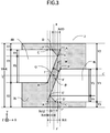
- FIG. 3 is an enlarged view of a pixel of the display panel according to this embodiment.
- a shielding line having a finite width W is provided at the trapezoid oblique sides.
- the oblique sides make an angle ⁇ with respect to the Y-axis direction. In this specification, the angle is zero in the +Y-axis direction and increases clockwise.
- a line parallel to the Y-axis and passing through the outermost point E of the aperture of the right-eye pixel 4R forms a boundary line between the non-overlapping region and overlapping region.
- the boundary line between the shielding part and aperture is parallel to the X-axis.
- Points F are an intersection between the boundary line at the lower base and a line parallel to the Y-axis and passing through the point E' and an intersection between the oblique side of the right-eye pixel 4 and a line parallel to the Y-axis and passing through the point E'.
- a point A is an intersection between an extended line connecting a point B that is a vertex of the upper base of the nearly trapezoidal aperture of the right-eye pixel 4R and the point E and an extended line of the lower base of the nearly trapezoidal aperture.
- a point A' is an intersection similarly obtained for the left-eye pixel 4L.
- the points A and B' are on the same line parallel to the Y-axis and so are the points A' and B.
- a point C is an intersection between an extended line connecting the points A' and B and the lower base of the nearly trapezoidal aperture of the right-eye pixel 4R.
- a point C' is an intersection similarly obtained for the left-eye pixel 4L.
- a point D is situated between the points A and F and within the overlapping region width Xct2.
- a line connecting the points D and E and a line connecting the points D' and E' are oblique with respect to the Y-axis direction and intersect the center line a-a' of the display unit 4.
- a sub-pixel has a nearly trapezoidal aperture; the acute angle parts at the lower base of the trapezoid are shielded by a triangle enclosed by the points A, D, and E or a triangle enclosed by the points A', D', and E', making a hexagonal aperture.
- a right triangle enclosed by the points A, B, and C and a right triangle enclosed by the points A', B', and C' overlap with each other in the Y-axis direction, forming an overlapping region having an overlapping width Xct in the X-axis direction.
- the aperture of a sub-pixel is shielded by the triangle enclosed by the points A, D, and E or the triangle enclosed by the points A', D', and E', the overlapping region width Xct2 is smaller than Xct.
- the points A, B, and C and points A', B', and C' have the same positional relationship as the points A, B, and C and points A', B', and C' in the pixel shown in FIG. 36 .
- the area Sct2 of a triangle enclosed by the points A, D, and E is set so that the overlapping region width Xct2 is present and smaller than the area Sct1 of a triangle enclosed by the points A, B, and C.
- WX1 W / cos ⁇ .
- WY1 W / sin ⁇ .
- FIG. 4 is a graphical representation showing the distribution of vertical aperture width of the display panel 2 according to this embodiment.
- the total of the vertical aperture widths of the apertures of the right-eye and left-eye pixels 4R and 4L of the display unit 4 is not constant in the X-axis direction. It fluctuates in the center part of the display unit 4, namely near the overlapping region width Xct2.
- the vertical aperture width decreases from the region Xct toward the center of the display unit 4, has a minimal value, and then increases toward the overlapping region width Xct2.
- the distance between the flexion points 61R and 61L is Xct.
- the total of the vertical aperture widths of the sub-pixels is constant in the center part of the sub-pixels, decreases from the line segments B-C and B'-C' and increases from the points E and E' toward the center line a-a' of the display unit 4.
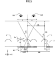
- FIG. 5 is a cross-sectional view showing an optical model using a lenticular lens.
- the image sorting means has to sort lights emitted from pixels in directions different from each other along the first direction in which the left-eye pixel 4L and right-eye pixel 4R are arranged, namely along the X-axis direction.
- the distance between a principal point or vertex of the lenticular lens 3 and a pixel is H
- the lenticular lens 3 has a refractive index n
- the lens pitch is L.
- the array pitch Xunit in the X-axis direction of display units 4 consisting of a left-eye pixel 4L or right-eye pixel 4R is equal to 2 x Xdot.
- the distance between the lenticular lens 3 and the observer is an optimum observation distance OD.
- the pixels enlarge and project images at intervals e.
- images are projected from left-eye and right-eye pixels 4L and 4R at intervals e on a virtual plane that is parallel to the lens and at a distance OD from the lens.
- the distance between the center of a cylindrical lens 3a at the center of the lenticular lens 3 and the center of a cylindrical lens 3a at the end of the lenticular lens 3 in the X-axis direction is WL.
- the distance between the center of a pixel consisting of left-eye and right-eye pixels 4L and 4R at the center of the display panel 2 and the center of a display pixel at the end of the display panel 2 in the X-axis direction is WP.
- the angles of light entering and emerging from a cylindrical lens 3a at the center of the lenticular lens 3 are ⁇ and ⁇ , respectively.
- the angles of light entering and emerging from a cylindrical lens 3a at the end of the lenticular lens 3 in the X-axis direction are ⁇ and ⁇ , respectively.
- the difference between the distances WL and WP is C and there are 2m sub-pixels in the region along the distance WP.
- the array pitch L of cylindrical lenses 3a and the array pitch Xdot of sub-pixels are related to each other. Therefore, the designer will determine one in accordance with the other.
- the lenticular lens 3 is designed in accordance with the display panel. Then, here, the array pitch Xdot of sub-pixels is treated as a constant.
- the refractive index n is determined by selection of the material of the lenticular lens 3.
- the distance OD between the lens and observer and the intervals e of images enlarged/projected by pixels are set to desired values. Using these values, the distance H between the lens vertex and pixel and the lens pitch L are determined. Then, the following mathematical formulae are established from Snell's law and geometric relations.
- the image sorting effect is maximized when the distance H between the vertex of the lenticular lens 3 and the pixel is equal to the focal length f of the lenticular lens 3. Assuming that the lens has a radius of curvature r, the radius of curvature r is obtained by the following mathematical formula.
- the above parameters are summarized as follows.
- the array pitch Xdot of sub-pixels is determined in accordance with the display panel 2.
- the observation distance OD and interval e of images enlarged/projected by pixels are determined in accordance with settings of the image display apparatus.
- the refractive index n is determined by the material of the lens.
- the lens array pitch L derived from the above and the distance H between the lens and pixel are parameters for determining the position at which light from pixels is projected on the observation plane.
- the radius of curvature r of the lens is a parameter changing the image sorting effect. In other words, when the distance H between the lens and pixel is constant and the radius of curvature r is deviated from the ideal state, images from right and left pixels are blurred and not clearly separated.
- the radius of curvature r is set between the maximum and minimum values with which images are effectively separated.
- FIG. 6 is an illustration showing an optical model of the minimum radius of curvature for calculating the image separation conditions of the lenticular lens.
- a triangle having a base given by the lens pitch L and a height given by the focal length f and a triangle having a base given by the width SP allowing for effective separation and a height H-f must be homologous. If so, the following mathematical formula is established and the minimum focal length value fmin can be obtained.
- the radius of curvature r is calculated from the focal length.
- the minimum value rmin of the radius of curvature r can be obtained from the following mathematical formula.
- FIG. 7 is an illustration showing an optical model of the maximum radius of curvature for calculating the image separation conditions of the lenticular lens.
- a triangle having a base given by the lens pitch L and a height given by the focal length f and a triangle having a base given by the width SP allowing for effective separation and a height H-f must be homologous. If so, the following mathematical formula is established and the maximum focal length value fmax can be obtained.
- the radius of curvature r is calculated from the focal length.
- the maximum value rmax of the radius of curvature can be obtained from the following mathematical formula.
- the lens in order for a lens to have the image sorting effect, the lens has to have a radius of curvature between the minimum and maximum values presented by the mathematical formulae obtained above.
- the range in which the radius of curvature r of a lens should be can be obtained using the following mathematical formula.
- the image display apparatus 1 of two observing points having a left-eye pixel 4L and a right-eye pixel 4R is described.
- the present invention is not restricted thereto.
- the present invention is similarly applicable to an image display apparatus of N observing points.
- N x m pixels are included in the region along the above-described distance WP.
- the spot diameter the width in the X-axis direction of a region in which blurring occurs according to the effective width of the above separation effect (SP in FIGS. 6 and 7 ) is termed "the spot diameter."
- the spot diameter is reduced, fluctuation in the vertical aperture at the boundary between right and left pixels is enhanced.
- the present invention shifts the focal point of the lens from the pixel plane as shown in FIGS. 6 and 7 so that local fluctuation in luminance of the vertical aperture is effectively reduced for higher image quality.
- defocusing effect the technique of shifting the focal point of the lens from the pixel plane to establish a blurring region for higher image quality.
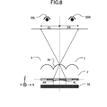
- FIG. 8 is an illustration showing an optical model using the image display apparatus 1 according to this embodiment.
- the display panel 2 As a backlight 15 emits light, the light emitted from the backlight 15 enters the display panel 2.
- the display panel 2 is driven by a control device (not shown) and the left-eye and right-eye pixels 4L and 4R display left-eye and right-eye images, respectively.
- the left-eye and right-eye images are parallax images forming a three-dimensional image.
- Light entering the left-eye and right-eye pixels 4L and 4R of the display panel 2 is transmitted through the apertures of these pixels, refracted by the lenticular lens 3, and directed toward regions EL and ER.
- the observer places his/her left eye 55L in the region EL and his/her right eye 55R in the region ER, whereby the observer can view the left-eye image with the left eye and the right-eye image with the right eye. In this way, the observer can view a three-dimensional image.
- FIG. 9 is a graphical representation showing an exemplary distribution of luminance in the image display apparatus of the present invention.
- the observation position X on the abscissa indicates the observation position of the observer in the image separation direction.
- the position 0 is where the midpoint between the two eyes of the observer is on a line vertically extended from the center of the display plane.
- Brightness Y is plotted as ordinate.
- the distribution of luminance corresponding to an image output to the left-eye appears on the -X side of the observer's position and the distribution of luminance corresponding to an image output to the right-eye appears on the +X side.
- the dotted lines present the distribution of luminance when an image is output to only one of the right-eye and left-eye pixels 4R and 4L.
- Y presents the distribution of luminance measured when the right pixel displays white and the left pixel displays black.
- Y presents the distribution of luminance measured when the right pixel displays black and the left pixel displays white.
- a bold line Y presents the distribution of luminance measured when the two pixels display the same image (the right pixel displays white and the left pixel displays white).
- Y (LBRB) presents the distribution of luminance measured when the two pixels display black.
- the distance between the points (X1, Y1) and (XR2, YR2) in the X-axis direction is equal to the width eR of a projected right-eye image.
- the distance between the points (X1, Y1) and (XL2, YL2) in the X-axis direction is equal to the width eL of a projected left-eye image.
- Reduction in luminance near the point (X0, Y0) is caused by the shielding part at the boundary between sub-pixels adjacent to each other in the X-axis direction. This reduction in luminance appears as 3D moire and ⁇ Yc and ⁇ Y/ ⁇ X, which will be described later, are used as indices of 3D moire assessment in this specification.
- a point (XL1, YL1) is where the luminance has the maximum value in the width eL of the projected left-eye image.
- a point (XR1, YR1) is where the luminance has the maximum value in the width eR of the projected right-eye image.
- the point (X0, Y0) is the minimum value of the distribution of luminance near the boundary between the width eL of the projected left-eye image and the width eR of the projected right-eye image.
- the 3D moire can be expressed by the following mathematical formulae from the ratio of the average luminance value of the points (XL1, YL1) and (XR1, YR2) to the point (X0, Y0).
- YC YL ⁇ 1 + YR ⁇ 1 / 2
- ⁇ Yc YC - Y ⁇ 0 / YC
- ⁇ Y / ⁇ X ⁇ Yc / XR ⁇ 1 - XL ⁇ 1
- the left-eye image mixes in the width eR of the projected right-eye image and the right-eye image mixes in the width eL of the projected left-eye image.
- the 3D crosstalk in the +X region can be presented by the following mathematical formula.
- the 3D crosstalk in the -X region can be presented by the following mathematical formula.
- 3D crosstalk 3DCT (X) is maximized at the points (X1, Y1), (XL2, YL2) and (XR2, YR2) and reaches a value of 100 %.
- the distributions of luminance Y (LWRB) and Y (LBRW) have the minimum values at points (XL3, YL3) and (XR3, YR3) and 3D crosstalk has a minimum value 3DCTmin.
- the minimum 3D crosstalk value 3Dmin is defined by the following mathematical formula and used as an index of assessment.
- FIG. 10 is a schematic illustration showing the relationship between the direction of light emitted from sub-pixels and 3D crosstalk.
- An angular range ⁇ s corresponds to the right-eye observation width eR in FIG. 9 , namely to (XR2 - X1).
- 3D crosstalk is low in an angular range ⁇ t and the observer can view stable three-dimensional display.
- 3D crosstalk is high in angular ranges ⁇ r1 and ⁇ r2 and the observer may experience discomfort in observation.
- the angular range ⁇ t in which excellent three-dimensional effect is obtained is formed by light emitted from a region near the center of a sub-pixel. Therefore, there is less influence from the sub-pixels adjacent in the X-axis direction and influence of 3D crosstalk is low.
- the angular ranges ⁇ r1 and ⁇ r2 are formed by light emitted from the ends of a sub-pixel. Therefore, light mixing in from the sub-pixels adjacent in the X-axis direction increases influence of 3D crosstalk. Consequently, the observer cannot have excellent three-dimensional effect.
- 3D crosstalk continuously increases from the angular range ⁇ s to the angular range ⁇ r1 while fluctuating, and the three-dimensional image quality drops.
- 3D crosstalk continuously increases from the angular range ⁇ s to the angular range ⁇ r2 while fluctuating, and the three-dimensional image quality drops. Then, 3D crosstalk reaches 100 % near the centers of the angular ranges ⁇ r1 and ⁇ r2.
- ⁇ r1 and ⁇ r2 are nearly equal.
- the ratio of the distance Xr to the sub-pixel pitch Xdot corresponds to the relation of the angular range ⁇ r ( ⁇ r1 or ⁇ r2) to the angular range ⁇ s of the three-dimensional observation range angle.
- the following mathematical formula is established.
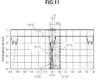
- FIG. 11 is a graphical representation showing the relationship between the distribution of vertical aperture width of a pixel and the spot diameter.
- 3D crosstalk can analytically be obtained by calculating the area ratio between the area Sl (X) to which the aperture of the left-eye pixel 4L contributes and the area Sr (X) to which the aperture region of the right-eye pixel 4R contributes. Assuming that the distance between the center line of the display unit 4 and the center of the spot diameter SP in the X-axis direction is Xr, the following mathematical formula is established.
- 3D crosstalk is equal to or lower than a given value, the observer does not experience subjective discomfort. Therefore, it is desirable that the angular range in which 3D crosstalk is equal to or lower than a given value is as large as possible.
- 3D crosstalk can be measured by, for example, a conoscope, goniometer, or Fourier system.
- a measuring device having such a system can measure the distribution of luminance with respect to view field angles and 3D crosstalk can be calculated by a method described later. There is no major difference in qualitative results from any measuring device; however, quantitative numeric values vary depending on measuring systems and device specifications.
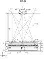
- the observer observed a three-dimensional image with the head fixed within the three-dimensional observation range as shown in FIG. 17 or with the head shifted outside the three-dimensional observation range.
- Subjective discomfort experienced by multiple observers was recorded according to the criteria. In other words, the average "visible quality" was recorded.
- the region to which a left-eye image is output and the region to which a right-eye image is output are formed by optically separating light emitted from each pixel and deflecting the light as shown by light beams 16.
- the three-dimensional observation range can be obtained by the relationship between such regions and the distance between the right and left eyes 55R and 55L.
- the three-dimensional visibility at the boundary between right and left images in the above three-dimensional observation range is deteriorated under the influence of 3D crosstalk. Therefore, the region in which 3D moire and 3D crosstalk are equal to or lower than given values can be defined as the three-dimensional visible range or three-dimensional observation range.
- an EZ Contrast is used to obtain measurements of the image display apparatus.
- This is not restrictive and any measuring device capable of measuring the distribution of luminance in angular directions can be used. In such a case, it is desirable that comparison is made with subjective three-dimensional observation range results from observers and a given value of 3D crosstalk is determined for the measuring device.
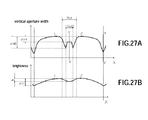
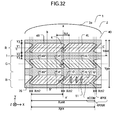
- FIG. 12 (A) is a graphical representation showing the relationship between the distribution of luminance in the X-axis direction of a pixel according to this embodiment and the spot diameter SP.
- FIG. 12 (B) is a graphical representation showing a part of FIG. 12 (A) .
- FIG. 13 (A) is a graphical representation showing the distribution of vertical aperture width of a pixel according to this embodiment and
- FIG. 13 (B) is a graphical representation showing the distribution of brightness.
- the pixel according to this embodiment has a gentle distribution of luminance as the spot diameter SP is increased because of augmented defocusing effect.
- the spot diameter SP becomes larger than Xct / 2
- two separate minimal values near the overlapping region are combined into one minimal value.
- the following mathematical formula is established from FIG. 13 .
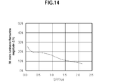
- FIG. 14 is a graphical representation showing the relationship between the spot diameter SP and the magnitude of luminance fluctuation ⁇ Yc in a pixel according to this embodiment.
- FIG. 15 is a graphical representation showing the relationship between the spot diameter SP and the gradient of luminance change ⁇ Y/ ⁇ X in a pixel according to this embodiment.
- FIG. 16 is a graphical representation showing the relationship between the spot diameter SP in a pixel according to this embodiment and the three-dimensional observation range.
- the region in which 3D crosstalk is equal to or lower than 7.5 % is the three-dimensional observation range.
- the spot diameter SP is 2 x Xct, 70 % or more of the three-dimensional observation range is ensured.
- the spot diameter SP is larger than Xct / 2,
- the spot diameter SP on the pixel plane is preferably in a range between WX1 / 2 and 2 x Xct.
- the spot diameter SP is WX1 / 2
- the oblique side region of the trapezoidal aperture is a marginal region where blurring occurs. Therefore, it is preferable that the spot diameter SP is larger than that.
- the spot diameter SP is 2 x Xct
- the blurring region is extended to the aperture region where the vertical aperture width is constant.
- the radius of curvature of the lens can be set within the range given by the following two formulae.
- the image display apparatus uses the spot diameter SP set in a range WX1 / 2 ⁇ SP ⁇ 2 x Xct, whereby defocusing effect is effectively applied and acute change in luminance within the spot diameter SP is leveled off so that a gentle distribution of luminance is obtained, 3D moire becomes less visible, and high quality three-dimensional images can be provided. Furthermore, even if the spot diameter SP is increased to obtain a gentle distribution of luminance, 3D moire becomes less visible without deteriorating 3D crosstalk because the overlapping region width Xct2 is smaller than Xct.
- the triangular shielding part enclosed by the points A, D, and E serves to reduce 3D moire and 3D crosstalk and contributes to improving the image quality.
- the shielding part has a large area and the overlapping region width Xct2 cannot be established, the aperture ratio will significantly reduce.
- the ratio of the area of the triangular shielding part enclosed by the points A, D, and E to the area of a triangle enclosed by the points A, B, and C has to be equal to or lower than a given value provided that the overlapping region width Xct2 can be established. This was found from the subjective assessment results. More specifically, the area of the triangular shielding part enclosed by the points A, D, and E is desirably equal to or smaller than 50 % of the area of a triangle enclosed by the points A, B, and C, and desirably equal to or smaller than 30 % for minimizing reduction in the aperture ratio.
- the vertical aperture width of a sub-pixel is not constant in the X-axis direction (see FIGS. 4 and 13 ). It decreases once from the region Xct toward the center of the display unit, has a minimal value, and then increases toward the overlapping region width Xct2. Therefore, fluctuation in the aperture width can be reduced with respect to shift in the X-axis direction.
- the points D and D' should be situated between the points A and F and between the points A' and F', respectively, namely within the overlapping region. This structure can accept larger shape variation due to the processing accuracy, improving the production yield and contributing to lower cost.
- Fluctuation in the Y-axis direction of the oblique wire having a width W is 1 / sin ⁇ with respect to fluctuation in the X-axis direction due to the processing accuracy of the production process and alignment variation between the TFT substrate and opposite substrate. Therefore, in the pixel structure of this embodiment, the angle ⁇ of the oblique wire can be increased to improve the aperture ratio and increase the margin of fluctuation in the Y-axis direction with respect to fluctuation in the X-axis direction. Furthermore, even if the angle ⁇ of the oblique wire is increased, 3D crosstalk is not deteriorated and, simultaneously, 3D moire can be less visible.
- the structure of the present invention is preferably applicable to a highly fine pixel having a sub-pixel pitch Xdot of 100 ⁇ m or smaller in which the angle ⁇ is preferably increased to improve the aperture ratio. From the subjective assessment results, the optimum angle ⁇ of the oblique wire is necessary to at least 17 degrees or larger.
- the wire angle is an acute angle
- the electric field tends to concentrate at the corners of the lower base of a nearly trapezoidal shape and distract the alignment of liquid crystal, causing light from the backlight to leak.
- the acute angle part is shielded, reducing leak light and improving the contrast.
- multiple observing points are set on the observation plane and light is emitted from the pixels for the observing points of all display units on the display plane toward the observing points.
- a light collection system Such a system because light for a specific observing point is collected to the corresponding observing point.
- FIG. 17 is a conceptual illustration showing the light collection of the image display apparatus according to this embodiment.
- a light collection system is characterized by reproducing light beams entering the eye of the observer for display.
- the present invention can effectively be applied to such a light collection system.
- FIG. 18 is a conceptual illustration of a spatial image system.
- a spatial image system does not set particular observing points. The difference from light collection systems is that light emitted from an object in the space is reproduced for display.
- An integral photography system, integral videography system, and integral imaging system fall under the category of spatial image systems.
- the observer at any position does not view only the pixels for the same observing point on the entire image plane.
- the observing point does not means “a point in the display region the user gazes at (viewing point)” but does mean “a position from which the user views the image display apparatus (observation position)” or "a point or region at/in which the eye of the user is situated.”
- the polarizing plate 11 does not need to be attached to the installed liquid crystal display panel; it can be provided outside the lenticular lens 3. In this way, the distance H between the pixels and lens can be reduced for the thickness of the polarizing plate 11. Then, a polishing process for thinning the glass can be eliminated. Furthermore, this placement allows for a larger room in designing the distance H between the pixels and lens, improving the degree of freedom in designing the three-dimensional observation range. Particularly, the three-dimensional display panel installed in a small device is designed to have the optimum observation distance of the three dimensional display near the panel, for example within reach of a hand. With the distance between the pixels and lens being reduced, the three-dimensional observation range width can more efficiently be improved. Furthermore, the above placement is effective in highly fine items having a pixel pitch Xunit of smaller than 100 ⁇ m.
- the cylindrical lens 3a of the display panel according to this embodiment can have the lens surface oriented to the opposite substrate 2b.
- this structure is effective in improving the degree of freedom of the optimum observation distance and in highly fine items.
- the image separation means can consist of an electrooptical element controlling the distribution of refractive index by liquid crystal molecules or an electrooptical element consisting of a combination of a concave-convex substrate having lens effect and liquid crystal molecules and using the liquid crustal molecules for switching.
- a parallax barrier consisting of transparent domains and opaque domains arranged alternately is applicable.
- the parallax barrier can be an electrooptical element in which the transparent and opaque domains are switched by liquid crystal molecules.
- the color filters of the same color continue in the X-axis direction. In this way, there is no need of shielding the same color region of the color filters and the color filter can be rectangular. Then, the color filter can easily be produced and the image display apparatus achieves lower cost.
- the color filter and shielding part can be provided to the TFT substrate 2a.
- the overlapping accuracy can be improved, whereby the width of the shielding part is reduced and the aperture efficiency is improved.
- 3D moire can be reduced, whereby the display quality is improved.
- defocusing effect serves to level off acute change in the distribution of luminance due to alignment variation, whereby a gentle distribution of luminance is obtained and 3D moire becomes less visible, providing high quality three-dimensional images.
- the shielding part 76 can be provided to a wire on the TFT substrate 2a, not in the region between a pair of sides oblique with respect to the Y-axis direction.
- the aperture ratio is less affected.
- this structure allows for a larger positional margin in the X-axis and a higher aperture ratio. This structure is particularly effective when the shielding part is formed on the substrate facing a substrate on which wires are formed.
- the first observing point pixel is the left-eye pixel 4L and the second observing point pixel is the right-eye pixel 4R.
- the first observing point pixel is the right-eye pixel 4R and the second observing point pixel is the left-eye pixel 4L.
- the three-dimensional display can be viewed in the same manner as in the original position by changing the order of image data.
- recent portable devices have a rotatable display screen for improved operability, requiring information to be provided regardless of the orientation of the image display apparatus 1 in the hand.
- the liquid crystal panel installed in the image display apparatus of this embodiment is not restricted to a TN mode liquid crystal drive system and other liquid crystal drive modes are applicable.
- the horizontal electric field mode include IPS (in-plane switching), FFS (fringe field switching), and AFFS (advanced fringe field switching) systems.
- the vertical alignment mode include MVA (multidomain vertical alignment) of which the multidomain scheme serves to reduce dependency on the field angle, PVA (patterned vertical alignment), and ASV (advanced super V) systems.
- liquid crystal display panels of an OCB (optically compensated bend) system or film compensated TN mode can preferably be used.
- the display panel 2 is a liquid crystal display panel using liquid crystal molecules as an electrooptical element.
- Applicable liquid crystal display panels include not only transmissive liquid crystal display panels but also reflective liquid crystal display panels, semitransmissive liquid crystal display panels, microreflective liquid crystal display panels in which the transmissive region is present at a larger ratio than the reflective region, and micrortransmissive liquid crystal display panels in which the reflective region is present at a larger ratio than the transmissive region.
- the display panel drive method is preferably applicable to TFT systems.
- Applicable thin film transistors of TFT systems include not only those of amorphous silicon, low temperature polysilicon, high temperature polysilicon, and monocrystalline silicon, but also those of organic materials such as pentacene, oxide metals such as zinc oxide, and carbon nanotubeb.
- the present invention is preferably applicable to thin film transistors of bottom gate, top gate, staggering, and reversed-staggering types regardless of their structure.
- the display panel 2 according to this embodiment is applicable to display panels other than those of liquid crystal types such as organic electroluminescence display panels, or PALC (plasma address liquid crystal).
- the non-emission region serves as the shielding region. Therefore, the same effect can be obtained by applying the structure of the shielding part of the present invention to the non-emission region.
- the terminal device is a cell-phone by way of example.
- the present invention is not restricted thereto. It is applicable to various portable terminal devices such as PDA, personal TVs, game machines, digital cameras, digital video cameras, and note type personal computers. Furthermore, it is applicable not only to portable terminal devices but also to various fixed terminal devices such as cash dispensers, automated vending machines, monitors, and television receivers.
- FIG. 19 is a plane view showing a pixel of the display panel according to this modified embodiment.
- the sub-pixel according to this embodiment is trapezoidal.
- the aperture is nearly trapezoidal and provided with a nearly triangular shielding part consisting of a polygon at the acute angle part.
- the nearly triangular shielding part consists of a quadrangle defined by points A, D, E, and F or points A', D', E, and F'.
- the point F of the sub pixel is situated in the overlapping region Xct2 and inside a triangle defined by the points A, E, and D.
- a line connecting the points F and D intersects a line a-a' that is the center line of the display panel.
- the angle between the line connecting the points F and D and the line a-a' is larger than the angle between the line connecting the points E and F and the line a-a'.
- the point D is situated outside a triangular region enclosed by the points A, B, and C.
- the point D' is situated outside a triangular region enclosed by the points A', B', and C'. Consequently, the points D and D' are flexion points where the vertical aperture width fluctuates in the X-axis direction. From these flexion points, the vertical aperture width decreases toward the center of the display unit 4.
- the width between the points D and D' in the X-axis direction is Xct3.
- the image display apparatus 1 of this modified embodiment is the same in structure and behavior as the image display apparatus 1 of Embodiment 1 except for the above-described matters.
- the line connecting the points F and D has a gradient smaller than the line connecting the points F and E. Fluctuation in the vertical aperture width from the point D to point F is smaller than fluctuation in the vertical aperture width from the point F to point E. Therefore, change in derivatives from the point D to point E is smaller. For this reason, with this structure, fluctuation in the distribution of luminance and in the distribution of brightness in the X-axis direction is reduced, 3D moire becomes less visible, and the shielding region including the points A, E, F, and D serves to reduce 3D crosstalk.
- the shielding part has blunt angles. Rounded corners due to the method of forming the shielding part can be minimized. Reduction in the aperture ratio due to the production method can be prevented. Furthermore, with this structure, there is no need of allying a highly accurate machining process for forming an acute angle part, achieving lower cost. Particularly, there are only blunt angles within the width Xct; shape variation due to the processing accuracy of the production process is reduced and local fluctuation in the vertical aperture width is reduced.
- the shielding region including the points A, E, F, and D can be used to adjust the overlapping region Xct2 as appropriate so as to achieve an acceptable level of 3D crosstalk and 3D moire to the observer.
- the degree of freedom of design can be increased even for a highly fine pixel consisting of sub-pixels of 100 ⁇ m or smaller.
- the nearly triangular shielding part at the acute angle part of the nearly trapezoidal aperture can consist of a polygon having four or more sides.
- the vertexes other than the point F being situated inside a triangular region defined by the points A, D, and E, the oblique side from the point D to point E has a gentle transition. In this way, fluctuation in the vertical aperture width is gentle and 3D moire becomes less visible.
- FIG. 20 is a plane view showing a pixel according to this embodiment.
- the display unit 4 of a pixel consists of sub-pixels for multiple observing points.
- a display unit 4 consists of four sub-pixels 4S arranged in the X-axis direction.
- Display units 4' and 4" each also consist of four sub-pixels 4S arranged in the X-axis direction.
- a pixel 40 consists of three display units 4, 4', and 4" arranged in the Y-axis direction and arranged in a matrix in the display region.
- the display units 4 in a single pixel are provided in the manner that red R, green G, and blue B color filters extend in the X-axis direction.
- Four columns of sub-pixels VX1, VX2, VX3, and VX4 can sort and output images for four observing points to the XZ plane as display units.
- the order of colors is not restricted to the above.
- a combination of red R, green G, and blue B can randomly be arranged.
- one pixel is not restricted to the above and can consist of three or more display units. In such a case, three or more colors can be used.
- the sub-pixels corresponding to the first observing point are provided in the column VX1; the sub-pixels corresponding to the second observing point, in the column VX2; the sub-pixels corresponding to the third observing point, in the column VX3; and the sub-pixels corresponding to the fourth observing point, in the column VX4.
- the columns VX1, VX2, VX3, and VX4 are provided with their respective pitches. This is not restrictive and can be set as appropriate.
- the aperture of a sub-pixel has a similar shape to that of the pixel of the display panel according to Embodiment 1.
- a shielding line oblique in a direction different from the Y-axis direction is provided in their boundary region.
- the oblique wire is provided between sub-pixels 4S adjacent to each other in the X-axis direction.
- the overlapping region where their apertures overlap with each other in the Y-axis direction is situated between sub-pixels 4S adjacent to each other in the X-axis direction and has an overlapping width Xct2.
- Nearly triangular shielding parts are provided at the acute angle parts of the nearly trapezoidal aperture of a sub-pixel, whereby the overlapping region width Xct2 can be set to a desired width as appropriate.
- 3D crosstalk is defined as crosstalk between the eyes.
- 3D crosstalk may be defined as crosstalk between images in the sense that "an image for an observing point leaks into an image for an adjacent observing point" and this is termed "inter-image crosstalk.”
- inter-image crosstalk In the case of two observing points as described in Embodiment 1, "3D crosstalk" between the eyes and "inter-image crosstalk” are the same and 3D crosstalk is desirably lower.
- presence of "inter-image crosstalk” contributes to yielding smooth interlocking parallax although it causes a double image; it is not always desirable that "inter-image crosstalk” is lower.
- the image display apparatus 1 of this modified embodiment is the same in structure and behavior as the image display apparatus 1 of Embodiment 1 except for the above-described matters.
- the image display apparatus 1 according to this modified embodiment has the equivalent effect to the image display apparatus 1 according to Embodiment 1.
- the sub-pixels become much finer as the number of observing points is increased. Therefore, leak light due to distracted alignment of the liquid crystal caused by electric field concentration accompanying the acute wire angle and reduction in the aperture ratio due to the shielding part formation method become obvious.
- the sub-pixel of this modified embodiment serves to reduce "inter-image crosstalk”
- the nearly triangular shielding parts at the acute angle parts serve for shielding, contributing to improvement in the contrast.
- all angles are blunt or right angles, whereby reduction in the aperture ratio due to the shielding part formation method can be prevented.
- an image display apparatus consisting of display units having four observing points is described.
- This modified embodiment is applicable to a three-dimensional display panel having N observing points in a display unit.
- An image display apparatus of N observing points can display a three-dimensional image with the addition of optimum three-dimensional information for each observing point, whereby a range in which an excellent three-dimensional image is viewed can be extended.
- FIG. 21 is a plane view showing a pixel of the display panel according to this embodiment.
- the sub-pixel of the display panel according to this embodiment consists of a nearly trapezoidal aperture and a trapezoidal shielding part enclosing it.
- the shielding part at the acute angle parts of a trapezoid has an inner edge curved outward from the aperture.
- the edge of the shielding part is formed so that the aperture is curved outward from the point D to point E.
- the curve has a curvature of an ellipse.
- the minor axis a of an ellipse E1 has a width Y2 and the major axis b has a width equal to a half of the aperture width WXR, namely (X1 + 2 x Xct2) / 2.
- Ellipses E1, E2, E1', and E2' are equal in the major and minor axes. In other words, the ellipses E1, E2, E1', and E2' are identical to each other and the shielding parts provided at the acute angle parts of the nearly trapezoidal shapes have the same curvature.
- the width of the minor axis a is smaller than the width Y1 of the aperture in the Y-axis direction and the width of the major axis b is (X1 + 2 x Xct2) / 2 or larger.
- the aperture widths WXR and WXL of sub-pixels in the X-axis direction are the maximum values of the aperture width in the X-axis direction in a sub-pixel and presented by X1 + 2 x Xct1 in the prior art structure (see FIG. 36 ).
- the ellipse E1 is inscribed to the nearly trapezoidal aperture at the point D. Therefore, the derivative of the vertical aperture width with respect to the X-axis direction is continuous at the point D.
- the point D is situated outside a triangular region enclosed by the points A, B, and C and so is the point D'. Consequently, the points D and D' are flexion points where the vertical aperture width fluctuates in the X-axis direction. From these flexion points, the vertical aperture width decreases toward the center of the display unit 4.
- the distance between the points D and D' in the X-axis direction is Xct3.
- the image display apparatus 1 of this embodiment is the same in structure and behavior as the image display apparatus 1 of Embodiment 1 except for the above-described matters.
- the derivative of the vertical aperture width with respect to the X-axis direction is continuous at the point D; therefore, fluctuation in the vertical aperture width at the point D is gentle. Therefore, fluctuation in the distribution of brightness and luminance is also gentle, whereby 3D moire becomes less visible.
- the acute angle part of the nearly trapezoidal aperture is not restricted to a curvature of an ellipse and a high-order function can apply to yield a curvature.
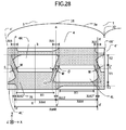
- FIG. 22 is a plane view showing a pixel of the display panel according to this embodiment.
- the pixel of the display panel according to this embodiment is nearly trapezoidal and is shielded by the upper and lower bases of a nearly trapezoidal aperture that are curved outward.
- a sub-pixel has an aperture consisting of three ellipses and four tangent lines tangent to them.
- the ellipses are an ellipse E5 or E5' having the center in the center part of the aperture and two ellipses E3 or E3' and E4 or E4' at the lower base of the nearly trapezoidal shape.
- the ellipses E5 and E5' are identical.
- the ellipses E3 and E3' and ellipses E4 and E4' are identical, respectively.
- the points D, E, and F are tangent points between a line and an ellipse. At each point, the derivative of the vertical aperture width with respect to the X-axis direction is continuous.
- the minor axis c of the ellipse E3 is larger than the vertical aperture width Y1.
- the vertical aperture width is maximized at the center line of the sub-pixel.
- the oblique width perpendicular to the Y-axis at the lower base of the nearly trapezoidal aperture is constant. This is not restrictive.
- the oblique width can be changed according to change in the vertical aperture width.
- a trapezoid connecting the four points A, B, A", and B" in the right-eye pixel 4R is referred to as a reference trapezoid T.
- a shielding region connecting the three points A, D, and E (Sa, hereafter) and a shielding region connecting the three points A", D", and E" (Sa', hereafter) are formed at the acute angle parts of the reference trapezoid T.
- a shielding region connecting the three points B, G, and F (Tb, hereafter) and a shielding region connecting the three points B", G", and F" (Sb', hereafter) are formed at the blunt angle parts of the reference trapezoid T.
- a region beyond the vertical aperture width Y1 at the upper base of the reference trapezoid T, namely a region enclosed by the points G, I, and G" (Sc, hereafter) is an aperture region newly provided outside the reference trapezoid T and contributes to improvement in the aperture ratio.
- the region Sc is larger than the total area of the above shielding regions. In other words, Sc > Sa + Sa' + Sb + Sb'. Therefore, as a whole, the aperture ratio of a sub-pixel is improved. The same applies to the left-eye pixel 4L.
- the image display apparatus 1 of this embodiment is the same in structure and behavior as the image display apparatus 1 of Embodiment 1 except for the above-described matters.
- the derivatives of the vertical aperture width with respect to the X-axis direction are continuous at the points where the ellipses contact lines; therefore, fluctuation in the vertical aperture width at the contact points is gentle. Therefore, fluctuation in the distribution of brightness and luminance is also gentle, whereby 3D moire becomes less visible.
- the pixel of the prior art embodiment is referred to as "Prior Art Pixel,” and the pixel of Embodiment 1 is referred to as “Pixel Level 1"; the pixel of Embodiment 2, as “Pixel Level 2”; and the pixel of Embodiment 3, as “Pixel Level 3.”
- FIG. 23 is a graphical representation showing the distribution of vertical aperture width in each pixel level, in which the vertical aperture width is plotted as ordinate and the position in the X-axis direction is plotted as abscissa.
- the difference ⁇ H33 between the maximum and minimum values of the vertical aperture width of the Pixel Level 3 is nearly equal to the difference ⁇ H22 between the maximum and minimum values of the vertical aperture width of the Pixel Level 2. Compared with those, the difference ⁇ H11 between the maximum and minimum values of the vertical aperture width of the Pixel Level 1 is smaller.
- the Prior Art Pixel has no fluctuation in the vertical aperture width.
- FIG. 24 is a graphical representation showing the derivatives with respect to the X-axis direction of the distribution of vertical aperture width of the pixel levels shown in FIG. 23 .
- the derivatives of the Pixel Level 3 with respect to the X-axis direction fluctuate less than the derivatives of the Pixel Level 2 with respect to the X-axis direction.
- the derivatives of the Pixel Levels 1 and 2 drastically fluctuate toward the center position.
- the derivatives of Pixel Levels 3 do not drastically fluctuate toward the center position; they continuously fluctuate.
- the derivatives of the vertical aperture width of the Pixel Level 3 with respect to the X-axis direction are continuous at the points E, C, and D (see FIG. 22 ); therefore, fluctuation in the vertical aperture width is gentle at these points, whereby 3D moire becomes less visible.
- FIG. 25 is a table showing the results of assessing the image display apparatuses to which the pixels of the above pixel levels are applied.
- the symbols double circle, O, ⁇ , x present subjective assessment results.
- the "double circle” indicates that no 3D crosstalk/3D moire is visible during observation and no sense of discomfort.
- the symbol “O” indicates a little 3D crosstalk/3D moire is visible during observation but no sense of discomfort.
- the symbol " ⁇ ” indicates that no sense of discomfort as long as three-dimensional display is observed within a 3D crosstalk/3D moire-optimized observation range.
- the symbol "x” indicates that 3D crosstalk/3D moire causes significant sense of discomfort and the visibility drops.
- the Prior Art Pixel successfully reduced 3D moire but failed to reduce 3D crosstalk, deteriorating the image quality.
- the pixels according to the present invention not only reduce 3D moire but also reduce 3D crosstalk, realizing a balanced image and improving the image quality.
- FIG. 26 is a plane view showing a pixel of the display panel according to this modified embodiment.
- a sub-pixel is asymmetric about a line b-b' and symmetric about the center O of the display unit 4.
- the aperture of a sub-pixel is curved outward at the upper and lower bases of a nearly trapezoidal pixel and has a maximal value maximizing the vertical aperture ratio.
- FIG. 27 (A) shows the distribution of vertical aperture ratio according to this modified embodiment
- FIG. 27 (B) shows the distribution of brightness of a pixel according to this modified embodiment.
- the vertical aperture width is maximized on the side near the lens convex part that is the lens principal axis and the brightness is simultaneously maximized.
- the image display apparatus 1 of this modified embodiment is the same in structure and behavior as the image display apparatus 1 of Embodiment 1 except for the above-described matters.
- the vertical aperture width has maximum values I and I' on the side near the lens principal axis. Therefore, the fluctuation ⁇ L in brightness of Xct2 defined by the lens separation effective width, namely the spot diameter SP becomes relatively smaller and 3D moire is reduced.
- the lenticular lens 3 is produced by metal molding, photolithography, or an inkjet technique.
- metal molding, photolithography, or an inkjet technique With any technique, a given shape is more ensured for a lens convex part 31 of a cylindrical lens 3a than for a lens trough part 32 of an adjacent cylindrical lens 3a, and the lens convex part 31 has a better optical performance. Furthermore, it is more difficult to remove any residue or adherent foreign materials from the lens trough part 32 than from the lens convex part 31, lowering the optical separation effect of the lens trough part 32.
- the concave-convex substrate has a steep convex part corresponding to the lens trough part 32, lowering the optical separation effect.
- the vertical aperture width is increased on the side near the lens convex part 31, whereby light emitted from a sub-pixel can be assigned to the lens convex part 31 with a high optical separation performance. Therefore, the pixel according to this modified embodiment prevents deterioration in three-dimensional image quality caused by an optical means such as a lenticular lens and an electrooptical element using liquid crystal, whereby light is further efficiently used, contributing to improvement in the transmittance and three-dimensional image quality.
- an optical means such as a lenticular lens and an electrooptical element using liquid crystal
- FIG. 28 is a plane view showing a pixel of the display panel according to this embodiment.
- the sub-pixel according to this embodiment is trapezoidal and has a nearly trapezoidal aperture. Nearly triangular shielding parts provided at the acute angle parts of the nearly trapezoidal shape of a sub-pixel have different structures in the respective acute angle parts. In this way, the aperture is asymmetric about the center line b-b' of a sub-pixel and symmetric about the center O of the display unit 4.
- the lenticular lens 3 consists of the cylindrical lenses 3a arranged in the X-axis direction and forming lens trough parts 32 between lens convex parts 31.
- the lens convex parts 31 and lens trough parts 32 are arranged alternately in the X-axis direction.
- the optical means can be a lens consisting of an electrooptical element using liquid crystal.
- the oblique wire corresponding to the end of the display unit 4 is provided at the lens trough part 32.
- the oblique wire at the center of the display unit 4 is provided at the lens convex part 31.
- the nearly triangular shielding part provided at the acute angle part at the end of the display unit 4 is different from the nearly triangular shielding part provided at the acute angle part at the center of the display unit 4.
- the pixel according to this embodiment prevents deterioration in three-dimensional image quality caused by an optical means such as a lenticular lens and an electrooptical element using liquid crystal as described above.
- the overlapping region width Xct2' or Xct2" where the display units 4 are adjacent to each other is smaller than the overlapping region width Xct2 at the center of the display unit 4.
- the overlapping region width Xct2' or Xct2" at the lens trough part 32 with a low optical separation performance is smaller than the overlapping region width Xct2 at the lens convex part 31 and is expressed by the following mathematical formula.
- the image display apparatus 1 of this embodiment is the same in structure and behavior as the image display apparatus 1 of Embodiment 1 except for the above-described matters.
- the spot diameter SP is large and the optical separation performance is low at the lens trough part 32.
- the overlapping region width Xct2' or Xct2" being smaller, the balance with the lens convex part 31 can be adjusted.
- the image display apparatus prevents deterioration in three-dimensional image quality caused by an optical means such as a lenticular lens and an electrooptical element using liquid crystal. Light can be used more efficiently, contributing to improvement in the transmittance and three-dimensional image quality.
- the nearly triangular shielding parts provided at the acute angle parts of a sub-pixel serve to make 3D moire less visible and reduce 3D crosstalk.
- FIG. 29 is a plane view showing a pixel of the display panel according to this embodiment.
- the sub-pixel according to this embodiment is trapezoidal and has a nearly trapezoidal aperture.
- the aperture is symmetric about the center O of the display unit 4.
- the nearly triangular shielding parts provided at the acute angle parts of the nearly trapezoidal shape have different structures at their respective acute angle parts of the trapezoid.
- the overlapping region width Xct2' or Xct2" of a part where the display units 4 are adjacent to each other is larger than the overlapping region width Xct2 at the center of a display unit 4.
- the overlapping region width Xct2' or Xct2" at the lens trough part 32 with a low optical separation performance is larger than the overlapping region width Xct2 at the lens convex part 31 and is expressed by the following mathematical formula.
- FIG. 30 is a schematic illustration showing an optical model of the image display apparatus 1 according to this embodiment.
- the display panel 2 has larger observation width eR' and EL' compared with those in the above-described embodiments.
- the refractive index n of the lenticular lens 3 and the distance H between the cylindrical lens 3a and pixels are adjusted to obtain a desired width.
- a nearly triangular shielding part is provided at the acute angle part of the nearly trapezoidal aperture at the center of the display unit 4.
- the overlapping region width Xct2 is smaller than Xct. Furthermore, in the overlapping region between display units adjacent to each other in the X-axis direction, no shielding part is provided at the acute angle part of the nearly trapezoidal aperture, whereby Xct2' and Xct2" are increased to improve the aperture ratio.
- ⁇ r2 is larger than ⁇ r1.
- the distance H is reduced to increase the observation widths eR' and eL'. Therefore, it is ensured that the light beam angle ⁇ t contributing to the three-dimensional observation range has a given value, not impairing the three-dimensional observation range.
- the image display apparatus 1 of this embodiment is the same in structure and behavior as the image display apparatus 1 of Embodiment 1 except for the above-described matters.
- the image display apparatus 1 has a shielding part at the center of the display unit 4, whereby excellent display properties including balanced 3D crosstalk and 3D moire at the center part of the three-dimensional view field are obtained. Furthermore, since the observation widths are increased and there is no shielding part between display units adjacent to each other in the X-axis direction, the aperture ratio can be improved without impairing the three-dimensional observation range.
- the observer may experience a so-called "reversed" state in which a right-eye image and a left-eye image are accidentally switched if he/she observes the screen from somewhere not right in front.
- the observation in the reversed state is not preferable because it causes eye fatigue or discomfort.
- three-dimensional observation is obviously difficult in the angular range ⁇ r2 and this angular range is large; therefore, the above reversed observation can be prevented. Therefore, highly safe three-dimensional images can be provided.
- the first observing point pixel 4L and second observing point pixel 4R constitute a display unit and the high optical separation performance region of the optical means is situated within a display unit and the low optical separation performance region is situated between display units.
- the shielding parts can be different in shape depending on whether it is within a display unit or between display units. Such a structure can prevent deterioration in three-dimensional image quality due to the optical means and allow for further efficient use of light, thereby contributing to improvement in the transmittance and three-dimensional image quality.
- FIG. 31 is a plane view showing a pixel of the display panel according to this embodiment.
- the sub-pixel according to this embodiment has a parallelogram shape.
- the sub-pixel has a near parallelogram aperture consisting of two sides nearly parallel to the X-axis and two oblique sides having an angle ⁇ with respect to the Y-axis direction.
- the sub-pixels are arranged in a matrix in the X-axis direction and in the Y-axis direction.
- the oblique sides of any sub-pixel are always at the same inclination ⁇ . Therefore, unlike the pixel structure described in Embodiment 1, the display unit 4 is not symmetric about a line b-b' parallel to the Y-axis and passing through the center of the sub-pixel. However, it is symmetric about the center O of the display unit 4 and has an equivalent layout structure after rotated by 180 degrees in the XY plane.
- a pixel 40 consists of three display units 4, 4', and 4" arranged in the Y-axis direction.
- the display units are colored in red R, green G, or blue B.
- the pixel 40 is square and arranged in a matrix with a pitch Xunit in the X-axis direction and with a pitch Ypix in the Y-axis direction in the display region. Furthermore, the pitch Xdot of sub-pixels in the X-axis direction is Xunit / 2 and the pitch Ydot of sub-pixels in the Y-axis direction is Xpix / 3.
- Red R, green G, blue color filters extend in the X-axis direction and create a nearly stripe pattern repeated in the Y-axis direction.
- the apertures of sub-pixels arranged in the X-axis direction are provided with no shift in the Y-axis direction.
- the shielding parts at the lower bases of the parallelograms are provided also with no shift in the Y-axis direction. In this way, the shielding parts at the lower bases of the parallelograms form a band of shielding part extending in the X-axis direction from one end to the other of the display region. In other words, the width Y2 of the shielding parts at the lower bases of the parallelogram pixels is nearly constant without fluctuating in the X-axis direction.
- the image display apparatus 1 of this embodiment is the same in structure and behavior as the image display apparatus 1 of Embodiment 1 except for the above-described matters.
- the image display apparatus 1 has shielding parts at the acute angle parts of the parallelogram aperture, reducing 3D crosstalk and reducing fluctuation in the vertical aperture width to male 3D moire less visible.
- An ordinary liquid crystal panel controls the rubbing on one substrate in one direction. Therefore, if each sub-pixel includes an asymmetric structure with respect to the rubbing direction, display properties change on the basis of sub-pixels, which appears as difference in display properties between observing points particularly in an image display apparatus.
- the display unit according to this embodiment consists of sub-pixels in a single outer shape, reducing difference in the staggering structure or electric field distribution structure between sub-pixels and diminishing difference in display properties between observing points that results from difference in the sub-pixel shape. Furthermore, with the above structure, with the sub-pixels being oriented equally, the liquid crystal alignment upon application of a voltage can be stabilized. In other words, difference in the image quality between observing points can be reduced and uniform images are output to the observing points to provide a high quality three-dimensional image. Furthermore, as the sub-pixels are in a single shape, the alignment of liquid crystal molecules is stabilized in each sub-pixel, reducing misalignment or leak light and improving the contrast.
- the shielding width at the lower base of the parallelogram is nearly constant in the X-axis direction, namely in the image separation direction, whereby light-dark particles according to fluctuation in the shielding width can be reduced.
- a liquid crystal drive mode using a horizontal or oblique electric field such as IPS (in-plane switching), FFS (fringe field switching), and AFFS (advanced fringe field switching) systems can improve the transmittance by using a single domain in which the liquid crystal molecules equally rotate. Therefore, the pixel structure of this embodiment is preferably applicable.
- FIG. 32 is a plane view showing a pixel of the display panel according to this embodiment.
- the sub-pixel according to this embodiment is in a parallelogram shape and has an aperture in a near parallelogram shape.
- the near parallelogram shape includes two nearly rectangular shapes consisting of two sides nearly parallel to the X-axis and two oblique sides having an inclination of - ⁇ or + ⁇ with respect to the Y-axis. Then, unlike the pixel structure described in Embodiment 1, this pixel structure is not symmetric about a line b-b' parallel to the Y-axis and passing through the center of the sub-pixel but symmetric about the center O of the display unit 4.
- the sub-pixels adjacent to each other in the Y-axis direction can align the liquid crystal molecules in different directions from each other. Then, multidomain compensation effect serves to reduce change in color tone when seen in an oblique direction.
- Near parallelogram sub-pixels having oblique sides with an inclination + ⁇ (> 0) and near parallelogram sub-pixels having oblique sides with an inclination - ⁇ ( ⁇ 0) are arranged alternately in the Y-axis direction.
- Sub-pixels having oblique sides with the same inclination are arranged in the X-axis direction.
- the oblique sides of sub-pixels arranged in the Y-axis direction are turned at every row while the oblique sides of sub-pixels arranged in the X-axis direction are inclined at the same angle.
- a pixel electrode 4PIX and an opposite electrode 4COM form an electrode pair 4PAIR arranged nearly in parallel with their lengthwise direction inclined in a direction different from the Y-axis direction.
- the inclination of the electrode pair 4PAIR with respect to the Y-axis direction is set to ⁇ or - ⁇ according to the oblique sides of the parallelogram.
- the electrode pair 4PAIR and the oblique wire at the oblique sides of a sub-pixel are parallel to each other.
- Electrodes pairs 4PAIR consisting of the pixel electrode 4PIX and opposite electrode 4COM are provided in the X-axis direction in a sub-pixel to create an electric field in the direction perpendicular to the inclination direction of the electrode pairs 4PAIR in the aperture of each sub-pixel.
- the electric field created between the pixel electrode 4PIX and opposite electrode 4COM includes at least a component neatly parallel to the substrate surface, whereby the major axis of liquid crystal molecules 51 can be rotated in a plane nearly parallel to the substrate surface.
- the pixel electrode 4PIX and opposite electrode 4COM are provided on the TFT substrate 2a (see FIG. 2 ).
- the pixel electrode 4PIX and opposite electrode 4COM apply an electric field nearly parallel to the plane to the liquid crystal molecules.
- the pixel electrode 4PIX and opposite electrode 4COM are not restricted to the above.
- An electrode on the TFT substrate 2a and an electrode on the opposite substrate 2b can be used to create an electric field nearly parallel to the substrate surface or an oblique electric field so as to drive the liquid crystal molecules.
- the pixel electrode 4PIX and opposite electrode 4COM are nearly parallel to each other and have an inclination ⁇ or - ⁇ with respect to the Y-axis direction according to the orientation of the oblique wire.
- the inclination of the pixel electrode 4PIX and the inclination of the opposite electrode 4COM are equal and an electric field created between the pixel electrode 4PIX and opposite electrode 4COM is nearly perpendicular to the oblique wire.
- the inclination ⁇ of the oblique sides of a sub-pixel and the inclination of the electrode pair 4PAIR can be different from each other.
- the pixel electrode 4PIX and opposite electrode 4COM are formed in the same layer. This is not restrictive and they can be formed in different layers.
- the liquid crystal drive mode is of an IPS (in-plane switching) system.
- IPS in-plane switching
- FFS far field switching
- AFFS advanced fringe field switching
- the above structure utilizes a positive liquid crystal agent with a positive dielectric anisotropy ( ⁇ > 0).
- the rubbing direction of the TFT substrate 2a is in the -Y direction or in the +Y direction. Therefore, the liquid crystal molecules 51 are initially aligned with their major axis nearly in parallel to the Y-axis direction.
- liquid crystal agent is not restricted to the positive type. It can be the negative type with a negative dielectric anisotropy ( ⁇ ⁇ 0).
- ⁇ ⁇ 0 negative dielectric anisotropy
- the rubbing direction is set in the -X direction or in the +X direction and the liquid crystal molecules 51 are aligned with the major axis nearly in parallel to the X-axis direction.
- the image display apparatus 1 of this embodiment is the same in structure and behavior as the image display apparatus 1 of Embodiment 1 except for the above-described matters.
- the above structure can uniformly drive the liquid crystal molecules in a sub-pixel and improve the transmittance. Furthermore, the electrode pair 4PAIR and the oblique sides of a sub-pixel are parallel to each other, whereby the pixel electrode 4PIX and opposite electrode 4COM can efficiently be provided, improving the aperture ratio.
- the sub-pixels arranged in the Y-axis direction can align the liquid crystal molecules in different directions from each other, whereby change in color tone between sub-pixels arranged in the Y-axis direction is compensated.
- multidomain compensation effect can be obtained.
- a negative liquid crystal agent when used, such a liquid crystal agent has difficulty in rising in the major axis direction for an electric field perpendicular to the substrate surface. Following the liquid crystal molecules rotating in the substrate plane, the liquid crystal molecules on the electrodes align, whereby the transmittance on the electrodes can be improved. Furthermore, difference between brightness on the electrodes and brightness between the electrodes is reduced, whereby 3D moire caused by this difference in brightness can be reduced.
- the domains are provided in a cycle of two rows by the turning direction.
- the color filters are provided in a cycle of three rows.
- the above structure yields multidomain compensation effect in every six rows.
- six rows of sub-pixels extend over a pitch of 6 x Ydot. As this pitch is increased, the image quality is deteriorated because of easily visible unevenness. For this reason, the subjective assessment revealed that it is desirable that the pixel pitch Ypix is 150 ⁇ m or smaller.
- the sub-pixel pitch in the Y-axis direction is desirably 50 ⁇ m or smaller.
- the alignment of liquid crystal may be unstable at the acute angle parts of a parallelogram because the electric field concentrates there.
- a shielding part for reducing 3D crosstalk is formed so that this unstable alignment part is shielded at the same time, improving the three-dimensional image quality and ensuring a high quality liquid crystal display panel.
- FIG. 33 is a perspective view of a fly-eye lens applicable to the image display apparatus according to this embodiment.
- An fly-eye lens 30 is applicable as the image separation means according to this embodiment.
- the fly-eye lens 30 can separate images not only in the X-axis direction but also in the Y-axis direction.
- FIG. 34 is a plane view showing a pixel of the display panel according to this embodiment.
- the display unit according to this embodiment consists of sub-pixels of multiple observing points.
- a pixel 40 consists of a total of 16 sub-pixels 4S in four rows and four columns.
- the pixel 40 is provided with red R, green G, blue B, and white W color filters.
- the four sub-pixels in VX1,VX2, VX3, or VX4 are used as a display unit to output images for four observing points.
- the four sub-pixels in VY1,VY2, VY3, or VY4 are used as a display unit to output images for four observing points.
- the colors of the color filters are not restricted to the above. For example, blue-green (cyan) or yellow can be used instead of white.
- the color filters are arranged in the manner that the same color is not duplicated in the rows and columns of a pixel.
- the shielding wire between sub-pixels is not parallel to Y-axis or to the X-axis; it is oblique.
- the shielding wire between sub-pixels is turned in every two columns in the X-axis direction and turned in every line in the Y-axis direction.
- Sub-pixels adjacent to each other in the X-axis direction overlap with each other in the Y-axis direction and the overlapping region has the same structure as in the image display apparatus 1 according to Embodiment 1.
- Sub-pixels adjacent to each other in the Y-axis direction overlap with each other in the X-axis direction and the overlapping region has the same structure as in the image display apparatus 1 according to Embodiment 1.
- the image display apparatus 1 of this embodiment is the same in structure and behavior as the image display apparatus 1 of Embodiment 1 except for the above-described matters.
- the overlapping region of sub-pixels according to this embodiment has the same structure as the overlapping region of sub-pixels according to Embodiment 1, the same effect regarding this matter is obtained.
- this structure can be installed in a mobile device having a rotatable screen.
- a mobile device 9 having a rotatable screen as shown in FIG. 35 .
- the display part of the cell-phone 9 has the above-described image display apparatus 1 installed.
- the X-axis direction of the image display apparatus 1 agrees with the vertical direction of the screen of the cell-phone 9 and the Y-axis direction of the image display apparatus 1 agrees with the horizontal direction of the screen of the cell-phone 9.
- the screen of the cell-phone 9 comprises a hinge with a rotation shaft, whereby it is rotatable. In this way, the image separation direction, namely the X-axis direction can be made nearly parallel to the line connecting the eyes of the observer for use.
- an image display apparatus composed of display units having four observing points is described.
- This embodiment is applicable to a three-dimensional display panel having N observing points in a display unit. Pixels arranged in N rows and N columns can be used in an image display apparatus having N observing points.
- Such a structure can display a three-dimensional image with the addition of three-dimensional information optimum for each observing point, whereby the range in which an excellent three-dimensional image is observed can be extended.
- the pixel provided on the +X side of a display unit is a left-eye pixel 4L and the pixel provided on the -X side of the display unit is a right-eye pixel 4R.
- the first observing point pixel is a right-eye pixel 4R and the second observing point pixel is a left-eye pixel 4L.
- the portable device 9 as shown in FIG. 35 has a rotatable display screen for improved operability, requiring information to be provided regardless of the orientation of the image display apparatus 1 in the hand. Then, the image display apparatus 1 of the present invention can effectively be used.
- An image display apparatus comprising:
- An image display apparatus comprising:
- An image display apparatus comprising:
- An image display apparatus comprising:
- a display panel having a plurality of display units which are arranged in a matrix and include at least a pixel displaying a first observing point image and a pixel displaying a second observing point image, wherein:
- a terminal device in which the image display apparatus according to any of Subjunction 1 to 24 is installed.
Landscapes
- Physics & Mathematics (AREA)
- General Physics & Mathematics (AREA)
- Optics & Photonics (AREA)
- Engineering & Computer Science (AREA)
- Multimedia (AREA)
- Signal Processing (AREA)
- Devices For Indicating Variable Information By Combining Individual Elements (AREA)
- Testing, Inspecting, Measuring Of Stereoscopic Televisions And Televisions (AREA)
- Liquid Crystal (AREA)
Applications Claiming Priority (1)
| Application Number | Priority Date | Filing Date | Title |
|---|---|---|---|
| JP2010207309A JP5796761B2 (ja) | 2010-09-15 | 2010-09-15 | 画像表示装置及び表示パネル |
Publications (2)
| Publication Number | Publication Date |
|---|---|
| EP2432242A2 true EP2432242A2 (fr) | 2012-03-21 |
| EP2432242A3 EP2432242A3 (fr) | 2016-04-20 |
Family
ID=44772787
Family Applications (1)
| Application Number | Title | Priority Date | Filing Date |
|---|---|---|---|
| EP11181200.4A Withdrawn EP2432242A3 (fr) | 2010-09-15 | 2011-09-14 | Appareil d'affichage d'images, panneau d'affichage |
Country Status (6)
| Country | Link |
|---|---|
| US (1) | US8810567B2 (fr) |
| EP (1) | EP2432242A3 (fr) |
| JP (1) | JP5796761B2 (fr) |
| KR (1) | KR101269330B1 (fr) |
| CN (1) | CN102445760B (fr) |
| TW (1) | TWI540881B (fr) |
Cited By (3)
| Publication number | Priority date | Publication date | Assignee | Title |
|---|---|---|---|---|
| EP2772785A1 (fr) * | 2013-02-27 | 2014-09-03 | NLT Technologies, Ltd. | Dispositif d'affichage d'image stéréoscopique |
| EP2713202A3 (fr) * | 2012-09-27 | 2015-11-25 | NLT Technologies, Ltd. | Élément d'affichage à cristaux liquides, appareil d'affichage d'image, procédé de commande d'appareil d'affichage d'image et dispositif portable |
| EP4068773A4 (fr) * | 2019-12-05 | 2023-12-06 | Beijing Ivisual 3D Technology Co., Ltd. | Procédé de réalisation d'affichage d'image 3d, et dispositif d'affichage 3d |
Families Citing this family (39)
| Publication number | Priority date | Publication date | Assignee | Title |
|---|---|---|---|---|
| US8797231B2 (en) * | 2009-04-15 | 2014-08-05 | Nlt Technologies, Ltd. | Display controller, display device, image processing method, and image processing program for a multiple viewpoint display |
| JP5776967B2 (ja) * | 2010-06-11 | 2015-09-09 | Nltテクノロジー株式会社 | 画像表示装置、画像表示装置の駆動方法、端末装置 |
| KR20130053103A (ko) * | 2011-11-15 | 2013-05-23 | 삼성디스플레이 주식회사 | 표시 패널 및 이를 포함하는 표시 장치 |
| US9341859B2 (en) * | 2012-07-06 | 2016-05-17 | Innolux Corporation | 3D image based alignment method |
| JP6099892B2 (ja) * | 2012-07-09 | 2017-03-22 | パナソニック インテレクチュアル プロパティ コーポレーション オブ アメリカPanasonic Intellectual Property Corporation of America | 映像表示装置 |
| JP6213812B2 (ja) | 2012-07-31 | 2017-10-18 | Tianma Japan株式会社 | 立体画像表示装置及び立体画像処理方法 |
| CN103268044B (zh) * | 2012-09-19 | 2016-04-20 | 上海天马微电子有限公司 | 一种裸眼3d液晶显示装置及其制造方法 |
| US9606367B2 (en) | 2012-10-16 | 2017-03-28 | Sharp Kabushiki Kaisha | Stereoscopic display device |
| TWI460514B (zh) * | 2012-12-27 | 2014-11-11 | Innocom Tech Shenzhen Co Ltd | 顯示裝置及其液晶顯示面板 |
| JP6277544B2 (ja) * | 2013-02-27 | 2018-02-14 | Tianma Japan株式会社 | 立体画像表示装置、端末装置 |
| CN103149730A (zh) * | 2013-03-04 | 2013-06-12 | 京东方科技集团股份有限公司 | 彩膜基板及其制作方法、液晶显示屏 |
| US20150254043A1 (en) * | 2014-03-04 | 2015-09-10 | Sung Jae Hwang | Display property determination |
| KR102181247B1 (ko) * | 2014-05-26 | 2020-11-23 | 엘지디스플레이 주식회사 | 입체 영상 표시 장치 |
| US9292926B1 (en) | 2014-11-24 | 2016-03-22 | Adobe Systems Incorporated | Depth map generation |
| US10606091B2 (en) | 2014-12-22 | 2020-03-31 | Tianma Microelectronics Co., Ltd. | Stereoscopic display device |
| US11074876B2 (en) | 2014-12-22 | 2021-07-27 | Tianma Microelectronics Co., Ltd. | Stereoscopic display device |
| TWI551846B (zh) * | 2015-04-22 | 2016-10-01 | 原相科技股份有限公司 | 感測元件及光學測距系統 |
| WO2016182502A1 (fr) | 2015-05-14 | 2016-11-17 | Medha Dharmatilleke | Boîtier/couvercle de dispositif mobile multi-usage intégré à un système de caméra et visionneur non électrique 3d/de multiples trames d'image et de vidéo pour photographie, vidéographie, et enregistrement de selfies 3d et/ou 2d de haute qualité |
| CN104965308B (zh) * | 2015-08-05 | 2017-12-22 | 京东方科技集团股份有限公司 | 三维显示装置及其显示方法 |
| JP6832064B2 (ja) * | 2016-01-13 | 2021-02-24 | 日本放送協会 | 立体像表示装置 |
| KR102522397B1 (ko) * | 2016-11-29 | 2023-04-17 | 엘지디스플레이 주식회사 | 무안경 방식의 입체영상 표시장치 |
| KR102839836B1 (ko) * | 2016-11-30 | 2025-07-30 | 엘지디스플레이 주식회사 | 표시장치 |
| KR102519065B1 (ko) | 2017-03-02 | 2023-04-07 | 삼성디스플레이 주식회사 | 유기 발광 표시 장치 |
| CN110520783B (zh) * | 2017-03-30 | 2021-09-14 | 夏普株式会社 | 显示装置 |
| KR102911854B1 (ko) * | 2018-10-05 | 2026-01-13 | 삼성전자주식회사 | 디스플레이 패널, 이를 이용한 3차원 디스플레이 장치 및 3차원 hud 장치 |
| CN111599283B (zh) | 2019-02-20 | 2022-03-15 | 财团法人工业技术研究院 | 透明显示装置 |
| US12108015B2 (en) | 2020-01-09 | 2024-10-01 | JUC Holdings Limited | 2D digital image capture system, frame speed, and simulating 3D digital image sequence |
| US11917119B2 (en) * | 2020-01-09 | 2024-02-27 | Jerry Nims | 2D image capture system and display of 3D digital image |
| US20210392314A1 (en) * | 2020-01-09 | 2021-12-16 | JUC Holdings Limited | Vehicle terrain capture system and display of 3d digital image and 3d sequence |
| US20210297647A1 (en) * | 2020-01-09 | 2021-09-23 | Jerry Nims | 2d image capture system, transmission & display of 3d digital image |
| US12106501B2 (en) * | 2020-01-09 | 2024-10-01 | JUC Holdings Limited | Subsurface imaging and display of 3D digital image and 3D image sequence |
| KR102883431B1 (ko) * | 2020-07-13 | 2025-11-07 | 엘지디스플레이 주식회사 | 표시 패널 및 렌티큘러 렌즈들을 포함하는 입체 영상 표시 장치 |
| US11467320B2 (en) | 2020-12-24 | 2022-10-11 | Microsoft Technology Licensing, Llc | Head mounted display device having dynamically addressable shutter array |
| US12126896B2 (en) * | 2021-05-28 | 2024-10-22 | Jerry Nims | 2D digital image capture system and simulating 3D digital image and sequence |
| US12598278B2 (en) * | 2021-11-12 | 2026-04-07 | Jerry Nims | Single 2D digital image capture system processing, displaying of 3D digital image sequence |
| US12593020B2 (en) * | 2024-01-17 | 2026-03-31 | Jerry Nims | Single 2D image capture system, processing and display of 3D digital image |
| KR20230102887A (ko) * | 2021-12-30 | 2023-07-07 | 엘지디스플레이 주식회사 | 입체 영상 디스플레이 패널 |
| KR102924879B1 (ko) | 2022-01-04 | 2026-02-10 | 삼성디스플레이 주식회사 | 표시 장치 및 표시 장치 구동 방법 |
| CN120447209A (zh) * | 2025-06-06 | 2025-08-08 | 武汉华星光电技术有限公司 | 显示装置及其制备方法 |
Citations (3)
| Publication number | Priority date | Publication date | Assignee | Title |
|---|---|---|---|---|
| JPH10186294A (ja) | 1996-09-30 | 1998-07-14 | Sharp Corp | 空間光変調器および方向性ディスプレイ |
| JP2005208567A (ja) | 2003-12-25 | 2005-08-04 | Nec Corp | 画像表示装置、携帯端末装置、表示パネル及びレンズ |
| JP2010207309A (ja) | 2009-03-09 | 2010-09-24 | Panasonic Corp | ドラム式洗濯機 |
Family Cites Families (12)
| Publication number | Priority date | Publication date | Assignee | Title |
|---|---|---|---|---|
| GB9513658D0 (en) | 1995-07-05 | 1995-09-06 | Philips Electronics Uk Ltd | Autostereoscopic display apparatus |
| GB9713658D0 (en) * | 1997-06-28 | 1997-09-03 | Travis Adrian R L | View-sequential holographic display |
| JP5024800B2 (ja) * | 2003-12-25 | 2012-09-12 | Nltテクノロジー株式会社 | 画像表示装置 |
| US7965365B2 (en) * | 2004-09-03 | 2011-06-21 | Nec Lcd Technologies, Ltd | Image display device, portable terminal, display panel, and lens |
| JP4778261B2 (ja) * | 2005-04-26 | 2011-09-21 | 日本電気株式会社 | 表示装置及び端末装置 |
| JP4714115B2 (ja) * | 2006-09-07 | 2011-06-29 | 株式会社東芝 | 立体映像表示装置および立体映像表示方法 |
| JP4197716B2 (ja) * | 2006-10-03 | 2008-12-17 | 株式会社東芝 | 立体映像表示装置 |
| JP4834592B2 (ja) | 2007-03-29 | 2011-12-14 | 株式会社東芝 | 三次元映像表示装置 |
| US7995166B2 (en) * | 2007-05-07 | 2011-08-09 | Nec Lcd Technologies, Ltd. | Display panel, display device, and terminal device |
| JP5224236B2 (ja) * | 2007-05-07 | 2013-07-03 | Nltテクノロジー株式会社 | 表示パネル、表示装置及び端末装置 |
| JP5665255B2 (ja) | 2007-10-15 | 2015-02-04 | Nltテクノロジー株式会社 | 表示装置とその駆動方法、端末装置及び表示パネル |
| JP5152718B2 (ja) | 2007-12-26 | 2013-02-27 | Nltテクノロジー株式会社 | 画像表示装置および端末装置 |
-
2010
- 2010-09-15 JP JP2010207309A patent/JP5796761B2/ja active Active
-
2011
- 2011-09-06 TW TW100132038A patent/TWI540881B/zh not_active IP Right Cessation
- 2011-09-12 US US13/230,493 patent/US8810567B2/en active Active
- 2011-09-14 KR KR1020110092687A patent/KR101269330B1/ko not_active Expired - Fee Related
- 2011-09-14 EP EP11181200.4A patent/EP2432242A3/fr not_active Withdrawn
- 2011-09-15 CN CN201110274090.XA patent/CN102445760B/zh active Active
Patent Citations (3)
| Publication number | Priority date | Publication date | Assignee | Title |
|---|---|---|---|---|
| JPH10186294A (ja) | 1996-09-30 | 1998-07-14 | Sharp Corp | 空間光変調器および方向性ディスプレイ |
| JP2005208567A (ja) | 2003-12-25 | 2005-08-04 | Nec Corp | 画像表示装置、携帯端末装置、表示パネル及びレンズ |
| JP2010207309A (ja) | 2009-03-09 | 2010-09-24 | Panasonic Corp | ドラム式洗濯機 |
Non-Patent Citations (1)
| Title |
|---|
| NIKKEI ELECTRONICS, 6 January 2003 (2003-01-06), pages 26 - 27 |
Cited By (6)
| Publication number | Priority date | Publication date | Assignee | Title |
|---|---|---|---|---|
| EP2713202A3 (fr) * | 2012-09-27 | 2015-11-25 | NLT Technologies, Ltd. | Élément d'affichage à cristaux liquides, appareil d'affichage d'image, procédé de commande d'appareil d'affichage d'image et dispositif portable |
| US9217872B2 (en) | 2012-09-27 | 2015-12-22 | Nlt Technologies, Ltd. | Liquid crystal display element, image display apparatus, method for driving image display apparatus, and portable device |
| EP3093704A1 (fr) * | 2012-09-27 | 2016-11-16 | NLT Technologies, Ltd. | Appareil d'affichage à cristaux liquides pour afficher des images à 2d/3d |
| EP2772785A1 (fr) * | 2013-02-27 | 2014-09-03 | NLT Technologies, Ltd. | Dispositif d'affichage d'image stéréoscopique |
| US9638924B2 (en) | 2013-02-27 | 2017-05-02 | Nlt Technologies, Ltd. | Stereoscopic image display device |
| EP4068773A4 (fr) * | 2019-12-05 | 2023-12-06 | Beijing Ivisual 3D Technology Co., Ltd. | Procédé de réalisation d'affichage d'image 3d, et dispositif d'affichage 3d |
Also Published As
| Publication number | Publication date |
|---|---|
| TW201233147A (en) | 2012-08-01 |
| CN102445760B (zh) | 2015-06-10 |
| EP2432242A3 (fr) | 2016-04-20 |
| JP2012063556A (ja) | 2012-03-29 |
| TWI540881B (zh) | 2016-07-01 |
| JP5796761B2 (ja) | 2015-10-21 |
| US20120113100A1 (en) | 2012-05-10 |
| CN102445760A (zh) | 2012-05-09 |
| KR20120028842A (ko) | 2012-03-23 |
| KR101269330B1 (ko) | 2013-05-29 |
| US8810567B2 (en) | 2014-08-19 |
Similar Documents
| Publication | Publication Date | Title |
|---|---|---|
| US8810567B2 (en) | Image display apparatus | |
| US9217872B2 (en) | Liquid crystal display element, image display apparatus, method for driving image display apparatus, and portable device | |
| CN102749714B (zh) | 图像显示装置、显示面板和终端装置 | |
| JP5776967B2 (ja) | 画像表示装置、画像表示装置の駆動方法、端末装置 | |
| JP4371012B2 (ja) | 画像表示装置、携帯端末装置、表示パネル及びレンズ | |
| US8749722B2 (en) | Display device displaying an image for a first viewpoint and an image for a second viewpoint | |
| JP5301283B2 (ja) | 表示装置 | |
| CN102636895B (zh) | 液晶显示设备 | |
| JP5761498B2 (ja) | 画像表示装置、画像表示装置の駆動方法及び端末装置 | |
| US7995166B2 (en) | Display panel, display device, and terminal device | |
| JP2007500371A (ja) | 自動立体表示装置 | |
| KR20130023029A (ko) | 3차원 영상 표시 장치 | |
| JP5224236B2 (ja) | 表示パネル、表示装置及び端末装置 | |
| JP5024800B2 (ja) | 画像表示装置 |
Legal Events
| Date | Code | Title | Description |
|---|---|---|---|
| PUAI | Public reference made under article 153(3) epc to a published international application that has entered the european phase |
Free format text: ORIGINAL CODE: 0009012 |
|
| AK | Designated contracting states |
Kind code of ref document: A2 Designated state(s): AL AT BE BG CH CY CZ DE DK EE ES FI FR GB GR HR HU IE IS IT LI LT LU LV MC MK MT NL NO PL PT RO RS SE SI SK SM TR |
|
| AX | Request for extension of the european patent |
Extension state: BA ME |
|
| PUAL | Search report despatched |
Free format text: ORIGINAL CODE: 0009013 |
|
| AK | Designated contracting states |
Kind code of ref document: A3 Designated state(s): AL AT BE BG CH CY CZ DE DK EE ES FI FR GB GR HR HU IE IS IT LI LT LU LV MC MK MT NL NO PL PT RO RS SE SI SK SM TR |
|
| AX | Request for extension of the european patent |
Extension state: BA ME |
|
| RIC1 | Information provided on ipc code assigned before grant |
Ipc: G02B 27/22 20060101ALI20160316BHEP Ipc: H04N 13/00 20060101ALI20160316BHEP Ipc: H04N 13/04 20060101AFI20160316BHEP |
|
| 17P | Request for examination filed |
Effective date: 20161020 |
|
| RBV | Designated contracting states (corrected) |
Designated state(s): AL AT BE BG CH CY CZ DE DK EE ES FI FR GB GR HR HU IE IS IT LI LT LU LV MC MK MT NL NO PL PT RO RS SE SI SK SM TR |
|
| STAA | Information on the status of an ep patent application or granted ep patent |
Free format text: STATUS: THE APPLICATION HAS BEEN WITHDRAWN |
|
| 18W | Application withdrawn |
Effective date: 20170120 |