EP2432248A2 - Dispositif de support et dispositif électronique l'utilisant - Google Patents
Dispositif de support et dispositif électronique l'utilisant Download PDFInfo
- Publication number
- EP2432248A2 EP2432248A2 EP11177138A EP11177138A EP2432248A2 EP 2432248 A2 EP2432248 A2 EP 2432248A2 EP 11177138 A EP11177138 A EP 11177138A EP 11177138 A EP11177138 A EP 11177138A EP 2432248 A2 EP2432248 A2 EP 2432248A2
- Authority
- EP
- European Patent Office
- Prior art keywords
- guide rail
- supporting
- side wall
- disposed
- sliding element
- Prior art date
- Legal status (The legal status is an assumption and is not a legal conclusion. Google has not performed a legal analysis and makes no representation as to the accuracy of the status listed.)
- Withdrawn
Links
Images


Classifications
-
- H—ELECTRICITY
- H04—ELECTRIC COMMUNICATION TECHNIQUE
- H04R—LOUDSPEAKERS, MICROPHONES, GRAMOPHONE PICK-UPS OR LIKE ACOUSTIC ELECTROMECHANICAL TRANSDUCERS; ELECTRIC HEARING AIDS; PUBLIC ADDRESS SYSTEMS
- H04R1/00—Details of transducers, loudspeakers or microphones
- H04R1/20—Arrangements for obtaining desired frequency or directional characteristics
- H04R1/32—Arrangements for obtaining desired frequency or directional characteristics for obtaining desired directional characteristic only
- H04R1/34—Arrangements for obtaining desired frequency or directional characteristics for obtaining desired directional characteristic only by using a single transducer with sound reflecting, diffracting, directing or guiding means
- H04R1/345—Arrangements for obtaining desired frequency or directional characteristics for obtaining desired directional characteristic only by using a single transducer with sound reflecting, diffracting, directing or guiding means for loudspeakers
-
- F—MECHANICAL ENGINEERING; LIGHTING; HEATING; WEAPONS; BLASTING
- F16—ENGINEERING ELEMENTS AND UNITS; GENERAL MEASURES FOR PRODUCING AND MAINTAINING EFFECTIVE FUNCTIONING OF MACHINES OR INSTALLATIONS; THERMAL INSULATION IN GENERAL
- F16M—FRAMES, CASINGS OR BEDS OF ENGINES, MACHINES OR APPARATUS, NOT SPECIFIC TO ENGINES, MACHINES OR APPARATUS PROVIDED FOR ELSEWHERE; STANDS; SUPPORTS
- F16M11/00—Stands or trestles as supports for apparatus or articles placed thereon ; Stands for scientific apparatus such as gravitational force meters
- F16M11/02—Heads
- F16M11/04—Means for attachment of apparatus; Means allowing adjustment of the apparatus relatively to the stand
- F16M11/06—Means for attachment of apparatus; Means allowing adjustment of the apparatus relatively to the stand allowing pivoting
- F16M11/10—Means for attachment of apparatus; Means allowing adjustment of the apparatus relatively to the stand allowing pivoting around a horizontal axis
-
- F—MECHANICAL ENGINEERING; LIGHTING; HEATING; WEAPONS; BLASTING
- F16—ENGINEERING ELEMENTS AND UNITS; GENERAL MEASURES FOR PRODUCING AND MAINTAINING EFFECTIVE FUNCTIONING OF MACHINES OR INSTALLATIONS; THERMAL INSULATION IN GENERAL
- F16M—FRAMES, CASINGS OR BEDS OF ENGINES, MACHINES OR APPARATUS, NOT SPECIFIC TO ENGINES, MACHINES OR APPARATUS PROVIDED FOR ELSEWHERE; STANDS; SUPPORTS
- F16M13/00—Other supports for positioning apparatus or articles; Means for steadying hand-held apparatus or articles
-
- F—MECHANICAL ENGINEERING; LIGHTING; HEATING; WEAPONS; BLASTING
- F16—ENGINEERING ELEMENTS AND UNITS; GENERAL MEASURES FOR PRODUCING AND MAINTAINING EFFECTIVE FUNCTIONING OF MACHINES OR INSTALLATIONS; THERMAL INSULATION IN GENERAL
- F16M—FRAMES, CASINGS OR BEDS OF ENGINES, MACHINES OR APPARATUS, NOT SPECIFIC TO ENGINES, MACHINES OR APPARATUS PROVIDED FOR ELSEWHERE; STANDS; SUPPORTS
- F16M2200/00—Details of stands or supports
- F16M2200/02—Locking means
- F16M2200/025—Locking means for translational movement
- F16M2200/028—Locking means for translational movement by positive interaction, e.g. male-female connections
-
- H—ELECTRICITY
- H04—ELECTRIC COMMUNICATION TECHNIQUE
- H04R—LOUDSPEAKERS, MICROPHONES, GRAMOPHONE PICK-UPS OR LIKE ACOUSTIC ELECTROMECHANICAL TRANSDUCERS; ELECTRIC HEARING AIDS; PUBLIC ADDRESS SYSTEMS
- H04R2201/00—Details of transducers, loudspeakers or microphones covered by H04R1/00 but not provided for in any of its subgroups
- H04R2201/02—Details casings, cabinets or mounting therein for transducers covered by H04R1/02 but not provided for in any of its subgroups
- H04R2201/021—Transducers or their casings adapted for mounting in or to a wall or ceiling
Definitions
- This invention relates to a supporting structure and, more particularly, to a supporting module and an electronic device using the same.
- a torque hinge structure is used for assisting in opening or closing an object.
- the conventional torque hinge structure generates a torque mainly relying on interference cooperation or a friction force of an elastic sheet, and therefore the torque hinge structure needs many components. Further, to accurately control the torque, great precision of the dimension is needed, and therefore costs of the components of the torque hinge structure are high.
- This invention is to provide a supporting module and an electronic device using the same to improve the prior art.
- the invention provides a supporting module disposed between a first body and a second body.
- the supporting module includes a guide rail, a sliding element, an elastic element, and a supporting unit.
- the guide rail is fastened to the first body and has a first side wall and a second side wall facing each other.
- the first side wall has a plurality of first recessed portions
- the second side wall has a plurality of second recessed portions in a one-to-one correspondence with the first recessed portions.
- Each of the first recessed portions and the corresponding second recessed portion are recessed in opposite directions to allow the guide rail to have different width along a first direction.
- the sliding element is slidably disposed at the guide rail along the first direction.
- the elastic element is disposed at the sliding element and is positioned between the first side wall and the second side wall of the guide rail.
- Two ends of the supporting unit are rotatably disposed at the sliding element and the second body around a second direction vertical with the first direction.
- the elastic element may be an elastic sheet.
- the supporting unit may include a supporting rod, a first shaft, and a second shaft.
- the first shaft may be disposed at one end of the supporting rod and may be rotatably disposed at the sliding element around the second direction.
- the second shaft may be disposed at the other end of the supporting rod and may be rotatably disposed at the second body around the second direction.
- the two ends of the supporting rod may have a thread portion, respectively.
- the supporting module may further include a base fastened to the second body.
- the supporting unit may be rotatably disposed at the base around the second direction.
- each of the first recessed portions and the second recessed portions may be C-shaped.
- the invention further provides an electronic device including a first body, a second body, and a supporting module.
- the supporting module is disposed between the first body and the second body, and the supporting module includes a guide rail, a sliding element, an elastic element, and a supporting unit.
- the guide rail is fastened to the first body and has a first side wall and a second side wall facing each other.
- the first side wall has a plurality of first recessed portions
- the second side wall has a plurality of second recessed portions in a one-to-one correspondence with the first recessed portions.
- Each of the first recessed portions and the corresponding second recessed portion are recessed in opposite directions to allow the guide rail to have different width along a first direction.
- the sliding element is slidably disposed at the guide rail along the first direction.
- the elastic element is disposed at the sliding element and is positioned between the first side wall and the second side wall of the guide rail.
- Two ends of the supporting unit are rotatably disposed at the sliding element and the second body around a second direction vertical with the first direction.
- the elastic element may be an elastic sheet.
- the supporting unit may include a supporting rod, a first shaft, and a second shaft.
- the first shaft may be disposed at one end of the supporting rod and may be rotatably disposed at the sliding element around the second direction.
- the second shaft may be disposed at the other end of the supporting rod and may be rotatably disposed at the second body around the second direction.
- the two ends of the supporting rod may have a thread portion, respectively.
- the supporting module may further include a base fastened to the second body.
- the supporting unit may be rotatably disposed at the base around the second direction.
- each of the first recessed portions and the second recessed portions may be C-shaped.
- the electronic device may be a wall-sticker-type speaker.
- the first body and the second body can approach or be far away from each other via the cooperation of the sliding of the sliding element in the guide rail and the rotation of the supporting unit relative to the first body and the second body.
- the sliding element can be positioned at different places of the guide rail via the cooperation of the elastic element and the first recessed portion and the second recessed portion of the guide rail, thus allowing the first body and the second body to be positioned at different angles.
- the supporting module according to the invention is simple in structure and easy to operate, and manufacture cost is low and generality is better as well. Further, due to the supporting unit, the supporting module according to the invention can avoid quivering at the location away from the axle centre when the object is opened to a certain angle.
- FIG. 1 is a schematic diagram of an electronic device according to one preferred embodiment of the invention.
- FIG. 2 is an exploded diagram of an elastic element, a sliding element, and a supporting unit of a supporting module according to one preferred embodiment of the invention
- FIG. 3 is an assembly diagram of a sliding element and a guide rail of a supporting module according to one preferred embodiment of the invention.
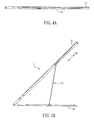
- FIG. 4A and FIG. 4B are schematic diagrams showing different angles between a first body and a second body of an electronic device according to one preferred embodiment of the invention.
- FIG. 1 is a schematic diagram of an electronic device according to one preferred embodiment of the invention.
- an electronic device 1 according to the embodiment includes a first body 11, a second body 12, and a supporting module 13.
- the electronic device 1 may be a wall-sticker-type speaker.
- the second body 12 can be fastened at the wall, and the first body 11 can approach or be far away from the second body 12.
- the volume of the electronic device 1 can be simultaneously controlled.
- the electronic device 1 can be other type of electronic device (such as a notebook computer).
- the supporting module 13 is disposed between the first body 11 and the second body 12.
- the supporting module 13 includes a guide rail 130, a sliding element 132, an elastic element 134 (shown in FIG 2 ), a supporting unit 136, and a base 138.
- the guide rail 130 is fastened to the first body 11.
- the sliding element 132 is slidably disposed at the guide rail 130 along the first direction D1.
- the elastic element 134 is disposed at the sliding element 132.
- the base 138 is fastened to the second body 12.
- Two ends of the supporting unit 136 are rotatably disposed at the sliding element 132 and the base 138 around a second direction D2.
- the second direction D2 is vertical with the first direction D1.
- FIG. 2 is an exploded diagram of an elastic element 134, a sliding element 132, and a supporting unit 136 of a supporting module 13 according to one preferred embodiment of the invention.
- FIG. 3 is an assembly diagram of a sliding element 132 and a guide rail 130 of a supporting module 13 according to one preferred embodiment of the invention. Please refer to FIG. 1 through FIG. 3 . The detailed structure of the supporting module 13 may be described hereinbelow.
- the guide rail 130 has a first side wall 1301 and a second side wall 1302 facing each other.
- the first side wall 1301 has a plurality of first recessed portions 1303, and the second side wall 1302 has a plurality of second recessed portions 1304 in a one-to-one correspondence with the first recessed portions 1303.
- Each of the first recessed portions 1303 and the corresponding second recessed portion 1304 are recessed in opposite directions to allow the guide rail 130 to have different width along the first direction D1.
- the edges of the first side wall 1301 and the second side wall 1302 are wave-shaped, respectively.
- the invention is not limited thereto.
- the first recessed portions 1303 can be recessed in different directions
- the second recessed portions 1304 can also be recessed in different directions as well.
- first recessed portion 1303 and the second recessed portion 1304 have the same shape and dimension.
- the first recessed portion 1303 and the second recessed portion 1304 are C-shaped, respectively.
- the invention is not limited thereto. In practice, the first recessed portion 1303 and the second recessed portion 1304 can have other shape (such as V-shaped or U-shaped) or dimension.
- the guide rail 130 has different width along the first direction D1.
- the maximum distance between the first recessed portion 1303 and the corresponding second recessed portion 1304 is W1
- the normal distance between the first side wall 1301 and the second side wall 1302 i.e. the distance between the first side wall 1301 and the second side wall 1302 when the first recessed portion 1303 and the second recessed portion 1304 are not disposed
- W1 and W2 the normal distance between the first side wall 1301 and the second side wall 1302
- the width of the guide rail 130 along the first direction D1 is between W1 and W2.
- the invention is not limited thereto.
- the elastic element 134 is disposed at the sliding element 132.
- the elastic element 134 may be an elastic sheet and it has a body 1340 and two elastic portions 1342 facing each other.
- the body 1340 of the elastic element 134 is U-shaped and positioned in the inside of the sliding element 132.
- the two elastic portions 1342 are U-shaped, respectively, and they protrude from the side walls of the sliding element 132 and are positioned against the first side wall 1301 and the second side wall 1302, respectively.
- the type and the shape of the elastic element 134 in the invention are not limited.
- the elastic element 134 can also be a spring.
- the sliding element 132 can be positioned in the guide rail 130 via the cooperation of the elastic element 134 and the first recessed portion 1303 and the second recessed portion 1304 of the guide rail 130.
- the elastic element 134 when the two elastic portions 1342 of the elastic element 134 are positioned against the first recessed portion 1303 and the corresponding second recessed portion 1304, respectively, the elastic element 134 is in a released state.
- the elastic element 134 can be positioned between the first recessed portion 1303 and the second recessed portion 1304 via the elastic force of the elastic element 134, thus allowing the sliding element 132 to be positioned at the guide rail 130.
- the sliding element 132 can be positioned at the guide rail 130 via the elastic force of the elastic element 134, and therefore the elastic force of the elastic element 134 needs to be overcome when the first body 11 and the second body 12 approach or are far away from each other.
- the supporting unit 136 when an external force exerts upon the first body 11 (or the second body 12) to allow the first body 11 (or the second body 12) to approach or be far away from the second body 12 (or the first body 11), the supporting unit 136 generates an reacting force to drive the sliding element 132 and the elastic element 134 to slide together.
- the elastic element 134 stops sliding and is positioned in one of the first recessed portions 1303 and the corresponding second recessed portion 1304. At this time, the elastic element 134 is in a released state, thus allowing the sliding element 132 to be positioned at the guide rail 130.
- the supporting unit 136 includes a supporting rod 1360, a first shaft 1361, and a second shaft 1362.
- the first shaft 1361 is disposed at one end of the supporting rod 1360 and is rotatably disposed at the sliding element 132 around the second direction D2.
- the second shaft 1362 is disposed at the other end of the supporting rod 1360 and is rotatably disposed at the base 138 around the second direction D2.
- the two ends of the supporting rod 1360 have a thread portion 1363, respectively.
- the first shaft 1361 and the second shaft 1362 have a threaded hole 1364, respectively.
- the two ends of the supporting rod 1360 are fastened in the threaded holes 1364 of the first shaft 1361 and the second shaft 1362, respectively. That is, the two ends of the supporting rod 1360 are screwed at the first shaft 1361 and the second shaft 1362, respectively.
- how the supporting rod 1360 is fastened to the first shaft 1361 and the second shaft 1362 is not limited in the invention.
- the supporting rod 1360 can be fastened at the first shaft 1361 and the second shaft 1362 via other methods (such as hooking or adhering), or the supporting rod 1360, the first shaft 1361, and the second shaft 1362 can be integrally formed.
- the sliding element 132 has two through holes 1321.
- the first shaft 1361 passes through the through hole 1321 and is capable of rotating relative to the sliding element 132 around the second direction D2, and therefore the supporting unit 136 can rotate relative to the first body 11 around the second direction D2.
- the relationship between the second shaft 1362 and the base 138 is the same with that between the first shaft 1361 and the sliding element 132, and it is not described for concise purpose. Therefore, the supporting unit 136 is capable of rotating relative to the second body 12 around the second direction D2.
- the invention is not limited thereto.
- the base 138 is not disposed, and the second shaft 1362 can be directly rotatably disposed at the second body 12 around the second directionD2.
- FIG. 4A and FIG. 4B are schematic diagrams showing different angles between a first body 11 and a second body 12 of an electronic device 1 according to one preferred embodiment of the invention. Please refer to FIG. 1 , FIG. 3 , FIG. 4A, and FIG. 4B .
- the supporting unit 136 rotates relative to the first body 11 and the second body 12 around the second direction D2
- the sliding element 132 slides in the guide rail 130 along the first direction D1
- the elastic element 134 is positioned between the first recessed portion 1303 and the corresponding second recessed portion 1304, thus positioning the first body 11 and the second body 12.
- the first body 11 and the second body 12 of the electronic device I form an angle between 0 and 45 degrees.
- the angle formed by the first body 11 and the second body 12 is 0 degree. That is, the first body 11 covers the second body 12.
- the sliding element 132 can slide to one end of the guide rail 130.
- the angle formed by the first body 11 and the second body 12 is 45 degrees. At this time, the sliding element 132 can slide to the other end of the guide rail 130.
- the invention is not limited thereto. In practice, the length of the guide rail 130 and the supporting rod 1360 can be disposed as needed, thus obtaining different angles between the first body 11 and the second body 12.
- the first body and the second body can approach or be far away from each other via the cooperation of the sliding of the sliding element in the guide rail and the rotation of the supporting unit relative to the first body and the second body.
- the sliding element can be positioned at different places of the guide rail via the cooperation of the elastic element and the first recessed portion and the second recessed portion of the guide rail, thus allowing the first body and the second body to be positioned at different angles.
- the supporting module according to the embodiment of the invention is simple in structure and easy to operate, and manufacture cost is low and generality is better as well. Further, due to the supporting unit, the supporting module according to the embodiment of the invention can avoid quivering at the location away from the axle centre when the object is opened to a certain angle.
Landscapes
- Engineering & Computer Science (AREA)
- General Engineering & Computer Science (AREA)
- Health & Medical Sciences (AREA)
- Otolaryngology (AREA)
- Mechanical Engineering (AREA)
- Physics & Mathematics (AREA)
- Acoustics & Sound (AREA)
- Signal Processing (AREA)
- Telephone Set Structure (AREA)
- Details Of Audible-Bandwidth Transducers (AREA)
- Casings For Electric Apparatus (AREA)
- Mounting Of Printed Circuit Boards And The Like (AREA)
Applications Claiming Priority (1)
| Application Number | Priority Date | Filing Date | Title |
|---|---|---|---|
| CN2010102886288A CN102413647A (zh) | 2010-09-21 | 2010-09-21 | 支撑模块及应用其的电子装置 |
Publications (2)
| Publication Number | Publication Date |
|---|---|
| EP2432248A2 true EP2432248A2 (fr) | 2012-03-21 |
| EP2432248A3 EP2432248A3 (fr) | 2013-08-28 |
Family
ID=44785204
Family Applications (1)
| Application Number | Title | Priority Date | Filing Date |
|---|---|---|---|
| EP11177138.2A Withdrawn EP2432248A3 (fr) | 2010-09-21 | 2011-08-10 | Dispositif de support et dispositif électronique l'utilisant |
Country Status (4)
| Country | Link |
|---|---|
| US (1) | US20120069541A1 (fr) |
| EP (1) | EP2432248A3 (fr) |
| JP (1) | JP2012070375A (fr) |
| CN (1) | CN102413647A (fr) |
Families Citing this family (1)
| Publication number | Priority date | Publication date | Assignee | Title |
|---|---|---|---|---|
| TWI515535B (zh) * | 2013-04-09 | 2016-01-01 | 和碩聯合科技股份有限公司 | 可支撐顯示裝置的結合裝置以及具有結合裝置的電子裝置 |
Family Cites Families (13)
| Publication number | Priority date | Publication date | Assignee | Title |
|---|---|---|---|---|
| US3958786A (en) * | 1974-11-27 | 1976-05-25 | Mann Gary A | Stand for musical instruments |
| US4496271A (en) * | 1982-09-30 | 1985-01-29 | East/West Industries, Inc. | Restraining fittings |
| US4753408A (en) * | 1987-04-16 | 1988-06-28 | David Warren | Adjustable attitude speaker stand |
| JP2574890Y2 (ja) * | 1991-07-30 | 1998-06-18 | 三洋電機株式会社 | スピーカボックス取付装置 |
| JPH10119659A (ja) * | 1996-10-21 | 1998-05-12 | Sony Corp | 車載用機器の取付部材 |
| JP2003093759A (ja) * | 2001-09-21 | 2003-04-02 | Kyosho Corp | 玩具用連結杆 |
| US7410143B2 (en) * | 2006-03-03 | 2008-08-12 | Hoolin Research Company Limited | Adjusting structure |
| US7925310B2 (en) * | 2007-06-05 | 2011-04-12 | Accton Technology Corporation | Communication device with stickup structure |
| WO2009154337A1 (fr) * | 2008-06-16 | 2009-12-23 | Lg Electronics Inc. | Appareil de support de dispositif d'affichage |
| TWI382733B (zh) * | 2008-08-25 | 2013-01-11 | Htc Corp | 滑蓋式電子裝置 |
| CN101725811A (zh) * | 2008-10-24 | 2010-06-09 | 鸿富锦精密工业(深圳)有限公司 | 支撑装置 |
| CN101725805B (zh) * | 2008-10-31 | 2012-03-14 | 鸿富锦精密工业(深圳)有限公司 | 支撑机构 |
| US8108970B2 (en) * | 2009-07-28 | 2012-02-07 | Shin Zu Shing Co., Ltd. | Hinge mechanism and an electronic device therewith |
-
2010
- 2010-09-21 CN CN2010102886288A patent/CN102413647A/zh active Pending
-
2011
- 2011-08-10 US US13/207,054 patent/US20120069541A1/en not_active Abandoned
- 2011-08-10 EP EP11177138.2A patent/EP2432248A3/fr not_active Withdrawn
- 2011-09-14 JP JP2011201037A patent/JP2012070375A/ja active Pending
Non-Patent Citations (1)
| Title |
|---|
| None |
Also Published As
| Publication number | Publication date |
|---|---|
| JP2012070375A (ja) | 2012-04-05 |
| US20120069541A1 (en) | 2012-03-22 |
| EP2432248A3 (fr) | 2013-08-28 |
| CN102413647A (zh) | 2012-04-11 |
Similar Documents
| Publication | Publication Date | Title |
|---|---|---|
| US20180341295A1 (en) | Hinge structure and electronic device | |
| US8634183B2 (en) | Automatic hinge opening assembly for electronic device | |
| US8959714B2 (en) | Dual-shaft synchronous motion device | |
| CN102573352A (zh) | 保护外壳及使用该保护外壳的电子设备组件 | |
| US20150160695A1 (en) | Hinge unit with simultaneous rotatable axles | |
| US9448583B1 (en) | Electronic device and hinge assembly | |
| US10571975B2 (en) | Hinge device for a portable computer | |
| US9777885B2 (en) | Support device | |
| US20200133341A1 (en) | Electronic device with flexible display | |
| US9138899B2 (en) | Suction device | |
| US9195264B2 (en) | Supporting apparatus and display device using the same | |
| CN105706019A (zh) | 用于计算装置的柔性铰链 | |
| US10392843B2 (en) | Hinge module and assembling method | |
| US20140007379A1 (en) | Hinge and an Electronic Device Incorporating the Same | |
| US20120243167A1 (en) | Mounting apparatus for data storage device | |
| CN104454906A (zh) | 螺柱结构及组装结构 | |
| US9377816B2 (en) | Docking device and electronic system therewith | |
| US20120275113A1 (en) | Electronic device with airflow guiding duct | |
| US10858869B2 (en) | Hinge assembly and electronic device using the same | |
| EP2432248A2 (fr) | Dispositif de support et dispositif électronique l'utilisant | |
| US20150108883A1 (en) | Computer host case structure | |
| US8084689B2 (en) | Hinge assembly and electronic device using the same | |
| CN203453271U (zh) | 多个止挡角度铰链 | |
| US20150035304A1 (en) | All-in-one device | |
| CN108119443B (zh) | 一种被动伸缩夹紧机构 |
Legal Events
| Date | Code | Title | Description |
|---|---|---|---|
| PUAI | Public reference made under article 153(3) epc to a published international application that has entered the european phase |
Free format text: ORIGINAL CODE: 0009012 |
|
| AK | Designated contracting states |
Kind code of ref document: A2 Designated state(s): AL AT BE BG CH CY CZ DE DK EE ES FI FR GB GR HR HU IE IS IT LI LT LU LV MC MK MT NL NO PL PT RO RS SE SI SK SM TR |
|
| AX | Request for extension of the european patent |
Extension state: BA ME |
|
| PUAL | Search report despatched |
Free format text: ORIGINAL CODE: 0009013 |
|
| AK | Designated contracting states |
Kind code of ref document: A3 Designated state(s): AL AT BE BG CH CY CZ DE DK EE ES FI FR GB GR HR HU IE IS IT LI LT LU LV MC MK MT NL NO PL PT RO RS SE SI SK SM TR |
|
| AX | Request for extension of the european patent |
Extension state: BA ME |
|
| RIC1 | Information provided on ipc code assigned before grant |
Ipc: F16M 11/10 20060101ALI20130723BHEP Ipc: F16M 13/00 20060101ALI20130723BHEP Ipc: H04R 1/34 20060101AFI20130723BHEP |
|
| STAA | Information on the status of an ep patent application or granted ep patent |
Free format text: STATUS: THE APPLICATION IS DEEMED TO BE WITHDRAWN |
|
| 18D | Application deemed to be withdrawn |
Effective date: 20140301 |