EP2433084B1 - Missile guidé - Google Patents
Missile guidé Download PDFInfo
- Publication number
- EP2433084B1 EP2433084B1 EP10784603.2A EP10784603A EP2433084B1 EP 2433084 B1 EP2433084 B1 EP 2433084B1 EP 10784603 A EP10784603 A EP 10784603A EP 2433084 B1 EP2433084 B1 EP 2433084B1
- Authority
- EP
- European Patent Office
- Prior art keywords
- missile
- wings
- fins
- set forth
- aft
- Prior art date
- Legal status (The legal status is an assumption and is not a legal conclusion. Google has not performed a legal analysis and makes no representation as to the accuracy of the status listed.)
- Not-in-force
Links
- 238000000034 method Methods 0.000 claims description 6
- 238000013461 design Methods 0.000 description 6
- 230000001133 acceleration Effects 0.000 description 5
- 238000010586 diagram Methods 0.000 description 2
- 230000000087 stabilizing effect Effects 0.000 description 2
- 241000272517 Anseriformes Species 0.000 description 1
- 238000013459 approach Methods 0.000 description 1
- 238000004891 communication Methods 0.000 description 1
- 230000001010 compromised effect Effects 0.000 description 1
- 230000003247 decreasing effect Effects 0.000 description 1
- 230000001066 destructive effect Effects 0.000 description 1
- 238000011161 development Methods 0.000 description 1
- 238000010304 firing Methods 0.000 description 1
- 231100000225 lethality Toxicity 0.000 description 1
- 238000004519 manufacturing process Methods 0.000 description 1
- 230000002035 prolonged effect Effects 0.000 description 1
- 230000001681 protective effect Effects 0.000 description 1
- 230000000007 visual effect Effects 0.000 description 1
Images


Classifications
-
- F—MECHANICAL ENGINEERING; LIGHTING; HEATING; WEAPONS; BLASTING
- F42—AMMUNITION; BLASTING
- F42B—EXPLOSIVE CHARGES, e.g. FOR BLASTING, FIREWORKS, AMMUNITION
- F42B10/00—Means for influencing, e.g. improving, the aerodynamic properties of projectiles or missiles; Arrangements on projectiles or missiles for stabilising, steering, range-reducing, range-increasing or fall-retarding
- F42B10/02—Stabilising arrangements
- F42B10/14—Stabilising arrangements using fins spread or deployed after launch, e.g. after leaving the barrel
-
- F—MECHANICAL ENGINEERING; LIGHTING; HEATING; WEAPONS; BLASTING
- F42—AMMUNITION; BLASTING
- F42B—EXPLOSIVE CHARGES, e.g. FOR BLASTING, FIREWORKS, AMMUNITION
- F42B10/00—Means for influencing, e.g. improving, the aerodynamic properties of projectiles or missiles; Arrangements on projectiles or missiles for stabilising, steering, range-reducing, range-increasing or fall-retarding
- F42B10/60—Steering arrangements
- F42B10/62—Steering by movement of flight surfaces
- F42B10/64—Steering by movement of flight surfaces of fins
Definitions
- a guided missile having a projectile body and aerodynamic surfaces that stabilize, guide, and/or lift the projectile body during various stages of a flight path.
- Range e.g ., 25 nautical miles
- accuracy e.g ., within 10 meters of identified target
- effectiveness e.g ., greater than 99% lethality
- these key factors need to be balanced within a missile design to insure that all three are optimized. For example, while range can be prolonged by faster muzzle velocity, the resulting increased setback acceleration can negatively impact crucial instrumentation and thereby shortchange accuracy and/or effectiveness.
- a missile also often inherits other variables that afford little or no liberties during design development.
- the projectile body usually must have a size/shape to accommodate an intended artillery platform and/or gun barrel (e.g ., 155 mm diameter and 1 m length).
- a missile includes a payload (e.g ., a warhead), its size, shape, and/or weight are almost always dictated primarily by mission objectives.
- a missile design is provided that reduces costs, increases reliability, and/or simplifies structure without compromising key performance parameters. Range performance is achieved by enhanced acceleration capability and improved lift-to-drag ratio, not faster muzzle velocities and/or greater launch charges. In this manner, setback acceleration is decreased, whereby the missile's instrumentation can reside in a less reliability-threatening environment. And, thanks to lower launch loads, the missile's structural-strength requirements can be relaxed.
- the missile achieves its enhanced-acceleration feature by combining the functionality of certain aerodynamic surfaces.
- the missile comprises tail fins that perform a stabilizing function during the just-launched stage of the flight path and perform a guiding function during post-ballistic stages of the flight path.
- the missile achieves its improved-lift feature by a pair of wings that are deployed from a mid portion of the projectile body. By controlled maneuvering of the wings and the fins, the missile can cruise during an apogee stage, precisely adjust direction during a midcourse trajectory stage, and/or situate itself for a near vertical angle-of-attack during terminal trajectory.
- the missile can be constructed to have a conventional projectile-body shape) and to carry a payload adequate for most mission objectives.
- the projectile body can have a diameter ( e.g ., 155 mm) and length ( e.g ., 1 m) compatible with current and future artillery platforms and/or howitzers.
- the missile can provide accurate, first round fire-for-effect capacity.
- a missile includes: a projectile body having a fore-aft axis and comprising a nose portion, and a mid portion aft of the nose portion, and a tail portion aft of the mid portion; a bearing coupler within the projectile body allowing at least a part of the tail portion to rotate freely relative to the mid portion about the fore-aft axis; a clutch within the projectile body that engages/disengages to selectively allow/prevent rotation of the at least part of the tail portion; wings, stowed within pockets in the mid portion, that extend to deployed positions outside of the projectile body; fins stored within slots in the at least part of the tail portion, wherein the fins are biased to extend radially outward in roll-stabilizing orientations; and a deflector that deflects the fins from their roll-stabilizing orientations to angularly align their leading edges relative to the aft-fore axis in direction-controlling orientations.
- a method of missile flight includes the steps of: launching a missile from a launch unit; deploying fins of the missile with their leading edges in roll-stabilizing orientations; during an initial roll-stabilized flight regime, allowing free rotation of a tail of the missile that includes the fins; after the roll-stabilized flight regime, engaging a clutch of the missile to prevent tail rotation; and deflecting leading edges of the fins using a deflector of the missile.
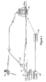
- a missile 10 is shown in a military setting as it follows a flight path from a launch unit 11 to a target 12.
- the launch unit 11 can comprise a howitzer 13, or other gun or cannon, having conventional specifications and/or capabilities.
- muzzle velocity can be 700 - 1000 m/s and the launch acceleration can be 8 - 15K.
- the illustrated flight path includes a just-launched stage (immediately after exit from the howitzer 13) and post-launch stages thereafter.
- the post-launch stages include a ballistic stage (determined primarily by muzzle velocity and launch angle), an apogee stage (upon reaching a cruise elevation), a mid-course trajectory stage (optimized for target range/arrival), and a terminal trajectory stage (optimized for target impact).
- Other flight paths are possible and contemplated. For example, if the missile 10 was on a battle-damage-assessment or other information-collecting mission, the flight path may not includes the latter trajectory stages.
- the missile's pursuit of the target 12 can be collaborated by other manned and unmanned units, such as a remote command unit 15, a field intelligence unit 16, and/or a global-positioning-system unit 17.
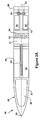
- the missile 10 comprises a projectile body 20 having a generally cylindrical shape with a fore-aft axis 21.
- the projectile body 20 can be shaped/sized to accommodate a conventional launch unit (e.g ., launch unit 11).
- the projectile body 20 can have a diameter of 155 mm and a length of 1 - 3 meters ( e.g ., 1 m, 1.55 m, 2.25 mm, etc.).
- the projectile body 20 comprises a nose portion 30, a mid portion 40 aft of the nose portion 30, and a tail portion 50 aft of the mid portion 40.
- the nose portion 30 can comprise a payload chamber 31 occupying most of its interior space.
- the midportion 40 comprises diametric wing slots 41 and can comprise instrument bays 42 occupying the space around the slots 41.
- the tail portion 50 can comprise a base part 51, a retainer part 52, a bearing coupler 53, and a clutch 54.
- the base part 51 can be fixedly mounted to the mid portion 40 and the retainer part 52 attached to the base part 51 by the bearing coupler 53.
- the retainer part 52 includes radial slots 55 ( e.g ., four) spaced circumferentially around its outer surface.
- the bearing coupler 53 allows the retainer part 52 to rotate freely relatively to the base 51 (and/or the mid portion 40) about the fore-aft axis 21.
- the clutch 54 can be engaged-disengaged to allow-prevent tail rotation.
- the entire tail portion 50 could be coupled to the mid portion 40 by the bearing coupler 53, whereby it would constitute the retainer part 52. In either event, at least part of the tail portion 50 can rotate freely relative to the mid portion 40.
- the retainer part 52 includes (has in it) the slots 55.
- the missile 10 can comprise a payload 60, contained within the chamber 31 in the nose portion 30.
- the payload 60 could comprise a warhead (e.g ., destructive munitions).
- the nose portion 30 and/or the chamber 31 can include other objects or devices, such as communication/guidance gear for actively or passively interacting with remote units 11, 15, 16, and/or 17.
- the missile 10 further comprises wings 70 and fins 80.
- the wings 70 are shown stowed within the pockets 41 in the mid portion 40 and the fins 80 are shown stored within the slots 55 in the tail portion 50.
- the wings 70 are shown in deployed positions and the fins 80 are shown in released conditions.
- the wings 70 each comprise an airfoil 71 having a leading edge 72.
- a wing deployer 73 within the mid portion 40 is operative to deploy the wings 70 from their stowed positions ( Figure 2A and Figure 3A ) to their deployed positions ( Figures 2B - 2C and Figures 3B - 3C .)
- the wings' leading edges 72 are aligned substantially parallel with the fore-aft axis 21.
- the wings' leading edges 72 extend radially outward from the fore-aft axis 21 in lift-imparting orientations.
- the wings 70 can comprise arms 74 connected to their inboard edges and the wing deployer can comprise a rod 75 to which the distal ends of the arms 74 are pivotally attached.
- the rod 75 can be located in an aft region of the mid portion 40, and the wings 70 can symmetrically move in the aft direction to deploy from the pockets 71.
- the rod 75 can be located in a fore region of the mid portion 40, and the wings 70 can symmetrically move in the fore direction to deploy from the pockets 71.
- the deployed position of the wings 70 can be rigid whereby their leading edges 72 remain at a constant deflection angle relative to the fore-aft axis 21.
- the fins 80 each comprise an airfoil 81 having a leading edge 82.
- An obturator 83 maintains the fins in their stored condition ( Figure 2A and Figure 3A ) until muzzle exit and releases them upon muzzle exit for movement to their released conditions ( Figures 2B - 2C and Figures 3B - 3C .)
- the obturator 83 is designed to break, fracture, or otherwise destruct to release the fins 80 during the just-launched stage of the flight path.
- the obturator 83 is located towards the aft end of the tail portion 50, to protect the fins 80 during firing and/or reduce pressure on protective covers (not shown).
- a fin deflector 84 within the tail portion 50, is operative to deflect the fins 80 from their roll-stabilizing orientations to angularly align their leading edges 82 relative to the aft-fore axis 81 in direction-controlling orientations.
- the missile 10 can further comprise a controller 90, such as schematically shown in Figure 4 .
- the controller 90 can comprise, for example, an output panel 91 that conveys control signals to the clutch 54, the wing deployer 73, and the fin deflector 84.
- the illustrated controller 90 also comprises an input panel 92 that receives information from onboard sensors, a GPS receiver 93, a collector 94, a command-unit receiver 95, a command-unit transmitter 96, a processor 97, and memory/storage 98.
- the controller 90 can be housed within the instrument bay 42 in the mid portion 40 and/or it can be powered by a battery 99 also housed within the instrument bay 42.
- the wings 70 Prior to launch of the missile 10, the wings 70 would be stowed within the mid portion 40, the fins 80 would be stored within the tail portion 50, and the obturator 83 would be intact. As the missile 10 exits the gun muzzle, the obturator 83 would release the fins 80 and they would move to released conditions whereat their leading edges 82 are in roll-stabilizing orientations.
- the clutch 54 would be disengaged, thereby allowing tail rotation during the ballistic stage of the path flight.
- the clutch 54 would remain disengaged, the wings 70 would stay in stowed positions, and the fins 80 would maintain roll-stabilizing orientations until the missile 10 reached the apogee stage of the flight path.
- the controller 90 can begin its contribution to the flight path. Specifically, the controller 90 can be programmed to send control signals (via its output panel 91) to the deployer 73 to deploy the wings 70.
- the wings 70 can be adapted to impart substantial lift to the projectile body 20, with little or no steering or guiding responsibilities. To this end, the tip-to-tip span of the wings 70 can be greater ( e.g ., 50% greater, 75% greater, 100% greater, 150% greater, and/or 200% greater) than the tail span of the fins 80.
- the wings' leading edge 72 can rigidly remain at a constant angle relative to the fore-aft axis 21.
- the clutch 54 can be engaged to prevent tail rotation.
- the controller 90 can signal the fin deflector 84 to deflect the fins' leading edges 82 in particular direction-determining orientations.
- the fins 80 and/or the deflector 84 are designed to deflect in a multitude of orientations (about a plurality of axes) for optimum guidance of the missile 10.
- the wings 70 can remain deployed or be returned to stowage (depending upon descent angle). And the fins 80 can continue to be maneuvered to direct the missile 10 towards the target 12.
- the wings 70 can be returned to stowed positions (if not already there) during the terminal trajectory stage, to allow a near vertical angle of attack.
- the controller 90 can ascertain the missile's stage in the flight path in a variety of ways. For example, the controller 90 can continuously obtain the missile's current global position (via its GPS receiver 93) and compare this to previously input positions ( e.g ., input prior to launch). Flight path stages can be ascertained by the altitude of the missile 10 and/or predetermined period of times. If the missile 10 and/or the controller 90 are equipped with target-seeking instrumentation ( e.g ., the collector 94), visual data concerning the target 12 can be used for this purpose. And/or a remote unit, such as the command unit 15, can receive data from and/or convey instructions to the controller 90 ( e.g ., via receiver 95 and transmitter 96).
- target-seeking instrumentation e.g ., the collector 94
- visual data concerning the target 12 can be used for this purpose.
- a remote unit such as the command unit 15, can receive data from and/or convey instructions to the controller 90 ( e.g ., via receiver 95 and transmitter 96).
- the missile 10 has design that reduces costs, increases reliability, and/or simplifies structure without compromising key performance parameters.
- the fins 80 function both as stabilizing components during the ballistic stage of the flight path and later as guiding components during post-ballistic stages of the flight path. This combined functionality removes the need for canards or other separate guiding components.
Landscapes
- Physics & Mathematics (AREA)
- Fluid Mechanics (AREA)
- Engineering & Computer Science (AREA)
- General Engineering & Computer Science (AREA)
- Aiming, Guidance, Guns With A Light Source, Armor, Camouflage, And Targets (AREA)
Claims (15)
- Missile (10) comprenant:un corps de projectile (20) présentant un axe avant-arrière (21) et comportant une partie de nez (30), et une partie centrale (40) en arrière de la partie de nez (30), et une partie de queue (50) en arrière de la partie centrale (40), un coupleur à roulement (53) à l'intérieur du corps de projectile (20) permettant à au moins une partie de la partie de queue (50) de tourner librement par rapport à la partie centrale (40) autour de l'axe avant-arrière (21);un embrayage (54) à l'intérieur du corps de projectile (20), qui s'engage/se désengage pour permettre/empêcher de façon sélective la rotation de ladite au moins une partie de la partie de queue (50);des ailerons (80) rangés à l'intérieur de fentes (55) dans ladite au moins une partie de la partie de queue (50), dans lequel les ailerons (80) sont poussés de façon à s'étendre radialement vers l'extérieur dans des orientations de stabilisation du roulis,caractérisé pardes ailes (70), rangées dans des poches (41) dans la partie centrale (40), qui s'étendent dans des positions déployées à l'extérieur du corps de projectile (20); etun déflecteur (84) qui dévie les ailerons (80) de leurs orientations de stabilisation du roulis afin d'aligner angulairement leurs bords d'attaque (82) par rapport à l'axe avant-arrière (21) dans des orientations de commande de direction.
- Missile (10) selon la revendication 1, comprenant en outre un dispositif de commande (90);
dans lequel le dispositif de commande (90) est programmé de façon à commander l'embrayage (54) pour empêcher la rotation de la queue lorsque l'on atteint un stade de guidage par ailerons de la trajectoire de vol. - Missile (10) selon la revendication 1, comprenant en outre un dispositif de commande (90);
dans lequel le dispositif de commande (90) est programmé de façon à commander un système de déploiement (73) pour déployer les ailes (70) lorsque l'on atteint un stade de déploiement des ailes de la trajectoire de vol. - Missile (10) selon la revendication 3, dans lequel le dispositif de commande (90) est programmé de façon à commander le système de déploiement (73) pour ramener les ailes (70) dans les poches (41) lorsque l'on atteint un stade de grand angle d'attaque de la trajectoire de vol.
- Missile (10) selon l'une quelconque des revendications 2 à 4, dans lequel le dispositif de commande (90) est programmé de façon à commander un déflecteur (84) pour dévier les ailerons (80) dans différents alignements angulaires dans lesquels leurs bords d'attaque (82) se trouvent dans des orientations de commande de direction.
- Missile (10) selon l'une quelconque des revendications 1 à 5, dans lequel l'envergure de bout à bout des ailes (70) est supérieure à l'envergure de queue des ailerons (80).
- Missile (10) selon l'une quelconque des revendications 1 à 5, dans lequel l'envergure de bout à bout des ailes (70) est supérieure d'au moins 50 % à l'envergure de queue des ailerons (80).
- Missile (10) selon l'une quelconque des revendications 1 à 7, comprenant en outre un obturateur (83) sur une extrémité arrière du corps de projectile (20);
dans lequel l'obturateur (83) protège les ailerons (80) pendant le lancement du missile (10). - Missile (10) selon l'une quelconque des revendications 1 à 8, comprenant en outre un système de déploiement (73), à l'intérieur de la partie centrale (40), qui déploie de façon sélective les ailes (70) hors des poches (41) jusqu'à des positions déployées.
- Missile (10) selon la revendication 9,
dans lequel le système de déploiement (73) comporte une barre (75);
dans lequel les ailes (70) comportent chacune une surface portante (71) et un bras (74) dont une extrémité est connectée à la surface portante (71) et une autre extrémité est connectée de façon pivotante à la barre (75); et
dans lequel les ailes (70) pivotent dans une direction arrière lorsqu'elles se déploient des poches (41) vers leurs positions déployées. - Missile (10) selon la revendication 9,
dans lequel le système de déploiement (73) comprend une barre (75);
dans lequel les ailes (70) comportent chacune une surface portante (71) et un bras (74) dont une extrémité est connectée à la surface portante (71) et une autre extrémité est connectée de façon pivotante à la barre (75); et
dans lequel les ailes (70) pivotent dans une direction avant lorsqu'elles se déplacent des poches (41) vers leurs positions déployées. - Procédé de vol d'un missile, le procédé comprenant les étapes suivantes:lancer un missile à partir d'une unité de lancement;déployer des ailerons du missile avec leurs bords d'attaque dans des orientations de stabilisation du roulis;pendant un régime initial de vol à roulis stabilisé, permettre la rotation libre d'une queue du missile qui comporte les ailerons;après le régime de vol à roulis stabilisé, engager un embrayage du missile pour empêcher la rotation de la queue par rapport à une partie centrale du missile;caractérisé en ce que l'on dévie les bords d'attaque des ailerons en utilisant un déflecteur du missile.
- Procédé selon la revendication 12, comprenant en outre le déploiement des ailes du missile pendant le vol.
- Procédé selon la revendication 13, dans lequel le déploiement des ailes est effectué après le commencement du régime de vol à roulis stabilisé, et avant la fin du régime de vol à roulis stabilisé.
- Procédé selon la revendication 13 ou la revendication 14, comprenant en outre, après le déploiement des ailes, le rangement des ailes alors que le missile est toujours en vol.
Applications Claiming Priority (2)
| Application Number | Priority Date | Filing Date | Title |
|---|---|---|---|
| US17939109P | 2009-05-19 | 2009-05-19 | |
| PCT/US2010/035178 WO2011019424A2 (fr) | 2009-05-19 | 2010-05-18 | Missile guidé |
Publications (2)
| Publication Number | Publication Date |
|---|---|
| EP2433084A2 EP2433084A2 (fr) | 2012-03-28 |
| EP2433084B1 true EP2433084B1 (fr) | 2013-05-08 |
Family
ID=43586715
Family Applications (1)
| Application Number | Title | Priority Date | Filing Date |
|---|---|---|---|
| EP10784603.2A Not-in-force EP2433084B1 (fr) | 2009-05-19 | 2010-05-18 | Missile guidé |
Country Status (3)
| Country | Link |
|---|---|
| US (1) | US20120068002A1 (fr) |
| EP (1) | EP2433084B1 (fr) |
| WO (1) | WO2011019424A2 (fr) |
Cited By (1)
| Publication number | Priority date | Publication date | Assignee | Title |
|---|---|---|---|---|
| WO2021170484A1 (fr) | 2020-02-27 | 2021-09-02 | Deutsches Zentrum für Luft- und Raumfahrt e.V. | Dispositif de déploiement d'ailette pour missile, missile et procédé pour faire fonctionner un missile |
Families Citing this family (14)
| Publication number | Priority date | Publication date | Assignee | Title |
|---|---|---|---|---|
| KR102396455B1 (ko) | 2009-02-02 | 2022-05-10 | 에어로바이론먼트, 인크. | 멀티모드 무인 항공기 |
| CN102596722B (zh) | 2009-09-09 | 2016-08-03 | 威罗门飞行公司 | 用于远程工作的无人驾驶航空飞行器的带有便携式rf透明发射管的抑制爆炸声的发射器的系统和设备 |
| WO2011066031A2 (fr) | 2009-09-09 | 2011-06-03 | Aerovironment, Inc. | Système de commande d'élevon |
| SE535991C2 (sv) * | 2011-07-07 | 2013-03-19 | Bae Systems Bofors Ab | Rotationsstabiliserad styrbar projektil och förfarande därför |
| KR102222167B1 (ko) * | 2012-06-07 | 2021-03-03 | 에어로바이론먼트, 인크. | 발사관 내에서 무인 항공기를 탈착가능하게 연결시키는 시스템 |
| WO2015179101A2 (fr) * | 2014-04-30 | 2015-11-26 | Bae Systems Land & Armaments L.P. | Munition tirée par un pistolet et dotée de listons |
| CA2930145A1 (fr) * | 2015-06-05 | 2016-12-05 | Lockheed Martin Corporation | Mecanisme de deploiement |
| FR3041744B1 (fr) * | 2015-09-29 | 2018-08-17 | Nexter Munitions | Projectile d'artillerie ayant une phase pilotee. |
| DE102015013913A1 (de) * | 2015-10-27 | 2017-04-27 | Deutsch Französisches Forschungsinstitut Saint Louis | Vollkalibriges, drallstabilisiertes Lenkgeschoss mit einer hohen Reichweite |
| KR101903250B1 (ko) | 2016-12-22 | 2018-10-01 | 주식회사 한화 | 정밀유도키트용 롤카나드 구동장치 및 이를 이용한 롤카나드 구동방법 |
| US11624594B1 (en) * | 2020-03-31 | 2023-04-11 | Barron Associates, Inc. | Device, method and system for extending range and improving tracking precision of mortar rounds |
| US20250361041A1 (en) * | 2021-10-27 | 2025-11-27 | Textron Systems Coporation | Modular rotorcraft and system for air-delivered effects or sensor payloads |
| US12540804B1 (en) * | 2024-09-20 | 2026-02-03 | Bae Systems Information And Electronic Systems Integration Inc. | Drag reduction fin deployment mechanism |
| CN119197205B (zh) * | 2024-11-01 | 2025-10-03 | 中国航空工业集团公司西安飞机设计研究所 | 一种内埋式挂载空空导弹及其挂载发射控制方法 |
Family Cites Families (11)
| Publication number | Priority date | Publication date | Assignee | Title |
|---|---|---|---|---|
| FR2321723A1 (fr) * | 1975-07-29 | 1977-03-18 | Thomson Brandt | Systeme de controle d'attitude et engin equipe d'un tel systeme |
| US4425785A (en) * | 1982-01-11 | 1984-01-17 | The United States Of America As Represented By The Administrator Of The National Aeronautics And Space Administration | Missile rolling tail brake torque system |
| US4565340A (en) * | 1984-08-15 | 1986-01-21 | Ford Aerospace & Communications Corporation | Guided projectile flight control fin system |
| GB2184414B (en) * | 1985-12-21 | 1989-10-18 | Plessey Co Plc | Rocket propelled vehicle |
| US5035378A (en) * | 1990-05-07 | 1991-07-30 | Spanovich Joseph P | Variable alignment mechanism |
| US5452864A (en) * | 1994-03-31 | 1995-09-26 | Alliant Techsystems Inc. | Electro-mechanical roll control apparatus and method |
| DE10130383A1 (de) * | 2001-06-23 | 2003-01-09 | Diehl Munitionssysteme Gmbh | Artillerie-Projektil mit austauschbarer Nutzlast |
| US6869044B2 (en) * | 2003-05-23 | 2005-03-22 | Raytheon Company | Missile with odd symmetry tail fins |
| US7412930B2 (en) * | 2004-09-30 | 2008-08-19 | General Dynamic Ordnance And Tactical Systems, Inc. | Frictional roll control apparatus for a spinning projectile |
| US20070018033A1 (en) * | 2005-03-22 | 2007-01-25 | Fanucci Jerome P | Precision aerial delivery of payloads |
| US7354017B2 (en) * | 2005-09-09 | 2008-04-08 | Morris Joseph P | Projectile trajectory control system |
-
2010
- 2010-05-18 EP EP10784603.2A patent/EP2433084B1/fr not_active Not-in-force
- 2010-05-18 WO PCT/US2010/035178 patent/WO2011019424A2/fr not_active Ceased
- 2010-05-18 US US12/781,868 patent/US20120068002A1/en not_active Abandoned
Cited By (3)
| Publication number | Priority date | Publication date | Assignee | Title |
|---|---|---|---|---|
| WO2021170484A1 (fr) | 2020-02-27 | 2021-09-02 | Deutsches Zentrum für Luft- und Raumfahrt e.V. | Dispositif de déploiement d'ailette pour missile, missile et procédé pour faire fonctionner un missile |
| DE102020105188A1 (de) | 2020-02-27 | 2021-09-02 | Deutsches Zentrum für Luft- und Raumfahrt e.V. | Flugkörper-Finnenausklappeinrichtung, Flugkörper und Verfahren zum Betrieb eines Flugkörpers |
| DE102020105188B4 (de) | 2020-02-27 | 2023-08-31 | Deutsches Zentrum für Luft- und Raumfahrt e.V. | Flugkörper-Finnenausklappeinrichtung, Flugkörper und Verfahren zum Betrieb eines Flugkörpers |
Also Published As
| Publication number | Publication date |
|---|---|
| US20120068002A1 (en) | 2012-03-22 |
| WO2011019424A3 (fr) | 2011-05-05 |
| EP2433084A2 (fr) | 2012-03-28 |
| WO2011019424A2 (fr) | 2011-02-17 |
Similar Documents
| Publication | Publication Date | Title |
|---|---|---|
| US20120068002A1 (en) | Guided missile | |
| US12078459B1 (en) | Methods for extended-range, enhanced-precision gun-fired rounds using g-hardened flow control systems | |
| US10788297B2 (en) | Artillery projectile with a piloted phase | |
| US6610971B1 (en) | Ship self-defense missile weapon system | |
| US8664575B2 (en) | Miniature missile | |
| US6135387A (en) | Method for autonomous guidance of a spin-stabilized artillery projectile and autonomously guided artillery projectile for realizing this method | |
| US5467940A (en) | Artillery rocket | |
| US8115149B1 (en) | Gun launched hybrid projectile | |
| US6481666B2 (en) | Method and system for guiding submunitions | |
| US11371814B2 (en) | Ground-projectile guidance system | |
| US20120048991A1 (en) | Tail thruster control for projectiles | |
| AU2020261387B2 (en) | Maneuvering aeromechanically stable sabot system | |
| US20040200375A1 (en) | Artillery projectile comprising an interchangeable payload | |
| EP2276998B1 (fr) | Appareil pour retenue et déploiement d'un aérofrein | |
| WO2020222250A1 (fr) | Conception de véhicule de ré-entrée modifiée avec système de commande de vol plané à trajectoire dynamique | |
| US20130255527A1 (en) | Projectile | |
| US20150284080A1 (en) | Special forces replenishment vehicle | |
| US10371495B2 (en) | Reaction control system | |
| US9121680B2 (en) | Air vehicle with control surfaces and vectored thrust | |
| US12209848B1 (en) | Despun wing control system for guided projectile maneuvers | |
| Geswender | Guided Projectiles Theory of Operation | |
| TROSKY | TRENDS OF PRECISION GUIDED PROJECTILES | |
| Geswender-Raytheon | Guided Projectiles Theory of Operation |
Legal Events
| Date | Code | Title | Description |
|---|---|---|---|
| PUAI | Public reference made under article 153(3) epc to a published international application that has entered the european phase |
Free format text: ORIGINAL CODE: 0009012 |
|
| 17P | Request for examination filed |
Effective date: 20111128 |
|
| AK | Designated contracting states |
Kind code of ref document: A2 Designated state(s): AL AT BE BG CH CY CZ DE DK EE ES FI FR GB GR HR HU IE IS IT LI LT LU LV MC MK MT NL NO PL PT RO SE SI SK SM TR |
|
| DAX | Request for extension of the european patent (deleted) | ||
| GRAP | Despatch of communication of intention to grant a patent |
Free format text: ORIGINAL CODE: EPIDOSNIGR1 |
|
| RIC1 | Information provided on ipc code assigned before grant |
Ipc: F42B 10/64 20060101AFI20121016BHEP Ipc: F42B 10/14 20060101ALN20121016BHEP |
|
| GRAS | Grant fee paid |
Free format text: ORIGINAL CODE: EPIDOSNIGR3 |
|
| GRAA | (expected) grant |
Free format text: ORIGINAL CODE: 0009210 |
|
| AK | Designated contracting states |
Kind code of ref document: B1 Designated state(s): AL AT BE BG CH CY CZ DE DK EE ES FI FR GB GR HR HU IE IS IT LI LT LU LV MC MK MT NL NO PL PT RO SE SI SK SM TR |
|
| REG | Reference to a national code |
Ref country code: GB Ref legal event code: FG4D |
|
| REG | Reference to a national code |
Ref country code: AT Ref legal event code: REF Ref document number: 611291 Country of ref document: AT Kind code of ref document: T Effective date: 20130515 Ref country code: CH Ref legal event code: EP |
|
| REG | Reference to a national code |
Ref country code: IE Ref legal event code: FG4D |
|
| REG | Reference to a national code |
Ref country code: DE Ref legal event code: R096 Ref document number: 602010007001 Country of ref document: DE Effective date: 20130704 |
|
| REG | Reference to a national code |
Ref country code: AT Ref legal event code: MK05 Ref document number: 611291 Country of ref document: AT Kind code of ref document: T Effective date: 20130508 |
|
| REG | Reference to a national code |
Ref country code: LT Ref legal event code: MG4D |
|
| REG | Reference to a national code |
Ref country code: NL Ref legal event code: VDEP Effective date: 20130508 |
|
| PG25 | Lapsed in a contracting state [announced via postgrant information from national office to epo] |
Ref country code: IS Free format text: LAPSE BECAUSE OF FAILURE TO SUBMIT A TRANSLATION OF THE DESCRIPTION OR TO PAY THE FEE WITHIN THE PRESCRIBED TIME-LIMIT Effective date: 20130908 Ref country code: FI Free format text: LAPSE BECAUSE OF FAILURE TO SUBMIT A TRANSLATION OF THE DESCRIPTION OR TO PAY THE FEE WITHIN THE PRESCRIBED TIME-LIMIT Effective date: 20130508 Ref country code: SE Free format text: LAPSE BECAUSE OF FAILURE TO SUBMIT A TRANSLATION OF THE DESCRIPTION OR TO PAY THE FEE WITHIN THE PRESCRIBED TIME-LIMIT Effective date: 20130508 Ref country code: GR Free format text: LAPSE BECAUSE OF FAILURE TO SUBMIT A TRANSLATION OF THE DESCRIPTION OR TO PAY THE FEE WITHIN THE PRESCRIBED TIME-LIMIT Effective date: 20130809 Ref country code: AT Free format text: LAPSE BECAUSE OF FAILURE TO SUBMIT A TRANSLATION OF THE DESCRIPTION OR TO PAY THE FEE WITHIN THE PRESCRIBED TIME-LIMIT Effective date: 20130508 Ref country code: SI Free format text: LAPSE BECAUSE OF FAILURE TO SUBMIT A TRANSLATION OF THE DESCRIPTION OR TO PAY THE FEE WITHIN THE PRESCRIBED TIME-LIMIT Effective date: 20130508 Ref country code: ES Free format text: LAPSE BECAUSE OF FAILURE TO SUBMIT A TRANSLATION OF THE DESCRIPTION OR TO PAY THE FEE WITHIN THE PRESCRIBED TIME-LIMIT Effective date: 20130819 Ref country code: LT Free format text: LAPSE BECAUSE OF FAILURE TO SUBMIT A TRANSLATION OF THE DESCRIPTION OR TO PAY THE FEE WITHIN THE PRESCRIBED TIME-LIMIT Effective date: 20130508 Ref country code: NO Free format text: LAPSE BECAUSE OF FAILURE TO SUBMIT A TRANSLATION OF THE DESCRIPTION OR TO PAY THE FEE WITHIN THE PRESCRIBED TIME-LIMIT Effective date: 20130808 Ref country code: PT Free format text: LAPSE BECAUSE OF FAILURE TO SUBMIT A TRANSLATION OF THE DESCRIPTION OR TO PAY THE FEE WITHIN THE PRESCRIBED TIME-LIMIT Effective date: 20130909 |
|
| PG25 | Lapsed in a contracting state [announced via postgrant information from national office to epo] |
Ref country code: CY Free format text: LAPSE BECAUSE OF FAILURE TO SUBMIT A TRANSLATION OF THE DESCRIPTION OR TO PAY THE FEE WITHIN THE PRESCRIBED TIME-LIMIT Effective date: 20130508 Ref country code: BG Free format text: LAPSE BECAUSE OF FAILURE TO SUBMIT A TRANSLATION OF THE DESCRIPTION OR TO PAY THE FEE WITHIN THE PRESCRIBED TIME-LIMIT Effective date: 20130808 Ref country code: HR Free format text: LAPSE BECAUSE OF FAILURE TO SUBMIT A TRANSLATION OF THE DESCRIPTION OR TO PAY THE FEE WITHIN THE PRESCRIBED TIME-LIMIT Effective date: 20130508 Ref country code: PL Free format text: LAPSE BECAUSE OF FAILURE TO SUBMIT A TRANSLATION OF THE DESCRIPTION OR TO PAY THE FEE WITHIN THE PRESCRIBED TIME-LIMIT Effective date: 20130508 |
|
| PG25 | Lapsed in a contracting state [announced via postgrant information from national office to epo] |
Ref country code: LV Free format text: LAPSE BECAUSE OF FAILURE TO SUBMIT A TRANSLATION OF THE DESCRIPTION OR TO PAY THE FEE WITHIN THE PRESCRIBED TIME-LIMIT Effective date: 20130508 |
|
| PG25 | Lapsed in a contracting state [announced via postgrant information from national office to epo] |
Ref country code: DK Free format text: LAPSE BECAUSE OF FAILURE TO SUBMIT A TRANSLATION OF THE DESCRIPTION OR TO PAY THE FEE WITHIN THE PRESCRIBED TIME-LIMIT Effective date: 20130508 Ref country code: SK Free format text: LAPSE BECAUSE OF FAILURE TO SUBMIT A TRANSLATION OF THE DESCRIPTION OR TO PAY THE FEE WITHIN THE PRESCRIBED TIME-LIMIT Effective date: 20130508 Ref country code: EE Free format text: LAPSE BECAUSE OF FAILURE TO SUBMIT A TRANSLATION OF THE DESCRIPTION OR TO PAY THE FEE WITHIN THE PRESCRIBED TIME-LIMIT Effective date: 20130508 Ref country code: CZ Free format text: LAPSE BECAUSE OF FAILURE TO SUBMIT A TRANSLATION OF THE DESCRIPTION OR TO PAY THE FEE WITHIN THE PRESCRIBED TIME-LIMIT Effective date: 20130508 Ref country code: BE Free format text: LAPSE BECAUSE OF FAILURE TO SUBMIT A TRANSLATION OF THE DESCRIPTION OR TO PAY THE FEE WITHIN THE PRESCRIBED TIME-LIMIT Effective date: 20130508 |
|
| REG | Reference to a national code |
Ref country code: IE Ref legal event code: MM4A |
|
| PG25 | Lapsed in a contracting state [announced via postgrant information from national office to epo] |
Ref country code: IT Free format text: LAPSE BECAUSE OF FAILURE TO SUBMIT A TRANSLATION OF THE DESCRIPTION OR TO PAY THE FEE WITHIN THE PRESCRIBED TIME-LIMIT Effective date: 20130508 Ref country code: MC Free format text: LAPSE BECAUSE OF FAILURE TO SUBMIT A TRANSLATION OF THE DESCRIPTION OR TO PAY THE FEE WITHIN THE PRESCRIBED TIME-LIMIT Effective date: 20130508 Ref country code: RO Free format text: LAPSE BECAUSE OF FAILURE TO SUBMIT A TRANSLATION OF THE DESCRIPTION OR TO PAY THE FEE WITHIN THE PRESCRIBED TIME-LIMIT Effective date: 20130508 Ref country code: NL Free format text: LAPSE BECAUSE OF FAILURE TO SUBMIT A TRANSLATION OF THE DESCRIPTION OR TO PAY THE FEE WITHIN THE PRESCRIBED TIME-LIMIT Effective date: 20130508 |
|
| PLBE | No opposition filed within time limit |
Free format text: ORIGINAL CODE: 0009261 |
|
| STAA | Information on the status of an ep patent application or granted ep patent |
Free format text: STATUS: NO OPPOSITION FILED WITHIN TIME LIMIT |
|
| 26N | No opposition filed |
Effective date: 20140211 |
|
| PG25 | Lapsed in a contracting state [announced via postgrant information from national office to epo] |
Ref country code: IE Free format text: LAPSE BECAUSE OF NON-PAYMENT OF DUE FEES Effective date: 20130518 |
|
| REG | Reference to a national code |
Ref country code: DE Ref legal event code: R097 Ref document number: 602010007001 Country of ref document: DE Effective date: 20140211 |
|
| REG | Reference to a national code |
Ref country code: CH Ref legal event code: PL |
|
| PG25 | Lapsed in a contracting state [announced via postgrant information from national office to epo] |
Ref country code: CH Free format text: LAPSE BECAUSE OF NON-PAYMENT OF DUE FEES Effective date: 20140531 Ref country code: LI Free format text: LAPSE BECAUSE OF NON-PAYMENT OF DUE FEES Effective date: 20140531 |
|
| PG25 | Lapsed in a contracting state [announced via postgrant information from national office to epo] |
Ref country code: MT Free format text: LAPSE BECAUSE OF FAILURE TO SUBMIT A TRANSLATION OF THE DESCRIPTION OR TO PAY THE FEE WITHIN THE PRESCRIBED TIME-LIMIT Effective date: 20130508 |
|
| PG25 | Lapsed in a contracting state [announced via postgrant information from national office to epo] |
Ref country code: SM Free format text: LAPSE BECAUSE OF FAILURE TO SUBMIT A TRANSLATION OF THE DESCRIPTION OR TO PAY THE FEE WITHIN THE PRESCRIBED TIME-LIMIT Effective date: 20130508 |
|
| PG25 | Lapsed in a contracting state [announced via postgrant information from national office to epo] |
Ref country code: TR Free format text: LAPSE BECAUSE OF FAILURE TO SUBMIT A TRANSLATION OF THE DESCRIPTION OR TO PAY THE FEE WITHIN THE PRESCRIBED TIME-LIMIT Effective date: 20130508 |
|
| PG25 | Lapsed in a contracting state [announced via postgrant information from national office to epo] |
Ref country code: MK Free format text: LAPSE BECAUSE OF FAILURE TO SUBMIT A TRANSLATION OF THE DESCRIPTION OR TO PAY THE FEE WITHIN THE PRESCRIBED TIME-LIMIT Effective date: 20130508 Ref country code: LU Free format text: LAPSE BECAUSE OF NON-PAYMENT OF DUE FEES Effective date: 20130518 Ref country code: HU Free format text: LAPSE BECAUSE OF FAILURE TO SUBMIT A TRANSLATION OF THE DESCRIPTION OR TO PAY THE FEE WITHIN THE PRESCRIBED TIME-LIMIT; INVALID AB INITIO Effective date: 20100518 |
|
| REG | Reference to a national code |
Ref country code: FR Ref legal event code: PLFP Year of fee payment: 7 |
|
| REG | Reference to a national code |
Ref country code: FR Ref legal event code: PLFP Year of fee payment: 8 |
|
| REG | Reference to a national code |
Ref country code: FR Ref legal event code: PLFP Year of fee payment: 9 |
|
| PG25 | Lapsed in a contracting state [announced via postgrant information from national office to epo] |
Ref country code: AL Free format text: LAPSE BECAUSE OF FAILURE TO SUBMIT A TRANSLATION OF THE DESCRIPTION OR TO PAY THE FEE WITHIN THE PRESCRIBED TIME-LIMIT Effective date: 20130508 |
|
| PGFP | Annual fee paid to national office [announced via postgrant information from national office to epo] |
Ref country code: DE Payment date: 20190508 Year of fee payment: 10 |
|
| PGFP | Annual fee paid to national office [announced via postgrant information from national office to epo] |
Ref country code: FR Payment date: 20190410 Year of fee payment: 10 |
|
| PGFP | Annual fee paid to national office [announced via postgrant information from national office to epo] |
Ref country code: GB Payment date: 20190515 Year of fee payment: 10 |
|
| REG | Reference to a national code |
Ref country code: DE Ref legal event code: R119 Ref document number: 602010007001 Country of ref document: DE |
|
| GBPC | Gb: european patent ceased through non-payment of renewal fee |
Effective date: 20200518 |
|
| PG25 | Lapsed in a contracting state [announced via postgrant information from national office to epo] |
Ref country code: GB Free format text: LAPSE BECAUSE OF NON-PAYMENT OF DUE FEES Effective date: 20200518 Ref country code: FR Free format text: LAPSE BECAUSE OF NON-PAYMENT OF DUE FEES Effective date: 20200531 |
|
| PG25 | Lapsed in a contracting state [announced via postgrant information from national office to epo] |
Ref country code: DE Free format text: LAPSE BECAUSE OF NON-PAYMENT OF DUE FEES Effective date: 20201201 |