EP2433095B1 - Dispositif inertiel de localisation, chaussure et equipement de la personne pourvus d'un tel dispositif - Google Patents
Dispositif inertiel de localisation, chaussure et equipement de la personne pourvus d'un tel dispositif Download PDFInfo
- Publication number
- EP2433095B1 EP2433095B1 EP10722047A EP10722047A EP2433095B1 EP 2433095 B1 EP2433095 B1 EP 2433095B1 EP 10722047 A EP10722047 A EP 10722047A EP 10722047 A EP10722047 A EP 10722047A EP 2433095 B1 EP2433095 B1 EP 2433095B1
- Authority
- EP
- European Patent Office
- Prior art keywords
- inertial unit
- support
- article
- inertial
- ground
- Prior art date
- Legal status (The legal status is an assumption and is not a legal conclusion. Google has not performed a legal analysis and makes no representation as to the accuracy of the status listed.)
- Not-in-force
Links
Images
Classifications
-
- G—PHYSICS
- G01—MEASURING; TESTING
- G01C—MEASURING DISTANCES, LEVELS OR BEARINGS; SURVEYING; NAVIGATION; GYROSCOPIC INSTRUMENTS; PHOTOGRAMMETRY OR VIDEOGRAMMETRY
- G01C21/00—Navigation; Navigational instruments not provided for in groups G01C1/00 - G01C19/00
- G01C21/10—Navigation; Navigational instruments not provided for in groups G01C1/00 - G01C19/00 by using measurements of speed or acceleration
- G01C21/12—Navigation; Navigational instruments not provided for in groups G01C1/00 - G01C19/00 by using measurements of speed or acceleration executed aboard the object being navigated; Dead reckoning
- G01C21/16—Navigation; Navigational instruments not provided for in groups G01C1/00 - G01C19/00 by using measurements of speed or acceleration executed aboard the object being navigated; Dead reckoning by integrating acceleration or speed, i.e. inertial navigation
- G01C21/166—Mechanical, construction or arrangement details of inertial navigation systems
-
- G—PHYSICS
- G01—MEASURING; TESTING
- G01C—MEASURING DISTANCES, LEVELS OR BEARINGS; SURVEYING; NAVIGATION; GYROSCOPIC INSTRUMENTS; PHOTOGRAMMETRY OR VIDEOGRAMMETRY
- G01C22/00—Measuring distance traversed on the ground by vehicles, persons, animals or other moving solid bodies, e.g. using odometers, using pedometers
- G01C22/006—Pedometers
-
- A—HUMAN NECESSITIES
- A61—MEDICAL OR VETERINARY SCIENCE; HYGIENE
- A61H—PHYSICAL THERAPY APPARATUS, e.g. DEVICES FOR LOCATING OR STIMULATING REFLEX POINTS IN THE BODY; ARTIFICIAL RESPIRATION; MASSAGE; BATHING DEVICES FOR SPECIAL THERAPEUTIC OR HYGIENIC PURPOSES OR SPECIFIC PARTS OF THE BODY
- A61H2201/00—Characteristics of apparatus not provided for in the preceding codes
- A61H2201/50—Control means thereof
- A61H2201/5058—Sensors or detectors
- A61H2201/5084—Acceleration sensors
-
- A—HUMAN NECESSITIES
- A61—MEDICAL OR VETERINARY SCIENCE; HYGIENE
- A61H—PHYSICAL THERAPY APPARATUS, e.g. DEVICES FOR LOCATING OR STIMULATING REFLEX POINTS IN THE BODY; ARTIFICIAL RESPIRATION; MASSAGE; BATHING DEVICES FOR SPECIAL THERAPEUTIC OR HYGIENIC PURPOSES OR SPECIFIC PARTS OF THE BODY
- A61H3/00—Appliances for aiding patients or disabled persons to walk about
- A61H3/06—Walking aids for blind persons
- A61H3/061—Walking aids for blind persons with electronic detecting or guiding means
-
- Y—GENERAL TAGGING OF NEW TECHNOLOGICAL DEVELOPMENTS; GENERAL TAGGING OF CROSS-SECTIONAL TECHNOLOGIES SPANNING OVER SEVERAL SECTIONS OF THE IPC; TECHNICAL SUBJECTS COVERED BY FORMER USPC CROSS-REFERENCE ART COLLECTIONS [XRACs] AND DIGESTS
- Y10—TECHNICAL SUBJECTS COVERED BY FORMER USPC
- Y10T—TECHNICAL SUBJECTS COVERED BY FORMER US CLASSIFICATION
- Y10T403/00—Joints and connections
- Y10T403/45—Flexibly connected rigid members
Definitions
- the present invention relates to an inertial locating device.
- the invention is particularly directed to the navigation of people who are unaware of the topography of the places in which they are and can not or do not wish to use the view as the main locating organ.
- the invention can thus be used by the visually impaired.
- the invention also relates to a shoe and a personal equipment provided with such a device.
- satellite navigation systems of the GPS (Global Positioning System for global positioning system) or Galileo type. These systems require the user to carry a satellite signal receiver which incorporates a computation unit arranged to calculate the position of the receiver from the satellite signals. Associated with cartographic software; these systems are particularly effective. However, it is not possible to capture the satellite signals in certain environments and especially inside certain buildings and for example in the metro.
- GPS Global Positioning System for global positioning system
- Galileo Galileo
- Navigation systems dedicated to navigation inside buildings require that the buildings are pre-equipped to allow triangulation identification of a device worn by the user. This forces the user to keep his movements in places he knows equipped.
- the investments to be made generally dissuade the organizations in charge of the administration of these buildings from installing such systems.
- the navigation of the users in the buildings thus remains generally assisted only by a signage guiding and locating.
- This mode of assistance to navigation is forbidden to the visually impaired and requires light conditions not always adapted to the circumstances (power failure for example).
- An object of the invention is to provide a means for further improving the accuracy of these systems by limiting the causes of external disturbance sensor.
- an inertial navigation device for equipping an object in intermittent contact with a surface, the device comprising an inertial unit comprising at least one inertial sensor, and mechanical connection means. from the inertial unit to the object.
- the connecting means are arranged to ensure, between the inertial unit and the object, a mechanical coupling when the object is not resting against the surface and a mechanical decoupling when the object bears against the surface of such in such a way that the inertial unit is substantially immobile with respect to the surface when the object bears against the surface.
- the surface is for example the ground.
- the object in question especially when held or worn by a user such as a shoe, can move under the voluntary or involuntary action of the user when in contact with the ground.
- the invention makes it possible to limit the transmission of these movements to the inertial unit during the phases of bearing against the ground while ensuring the transmission of the movements of the object when the object is moving relative to the ground. This allows to have a station immobility as long as possible during the phases of support of the object against the ground.
- the connecting means comprise a support defining a housing receiving the inertial central vertical sliding and having a lower surface intended to extend facing the surface when the object bears against the surface and, preferably, the lower surface is a bearing surface support against the surface.
- the support can provide protection for the inertial unit and facilitates attachment or integration of the inertial device to the object.
- the inertial unit is thus directly in contact with the ground or via a rigid plate while the support takes the support force of the device against the ground.
- the connecting means comprise a flexible wire connecting the inertial unit to the support and having a length such that the wire is taut when the object is lifted off the surface and loose when the object is in abutment against the surface and, advantageously, the wire extends in a conduit and has one end attached to the inertial unit and the opposite one end attached to a vertically slidably received counterweight in the support between a projecting position of the lower surface support to bear on the surface and a depressed position.
- the wire has a length adapted to both drive the inertial unit during the phases of "flight" where the object is off the ground and maximize the immobilization time of the inertial unit during the phases of support of the object against the ground.
- the invention also relates to a shoe in which the support forms a part of the sole and equipment of the person, such as a cane, a walker or a walking stick, equipped with a navigation device according to the invention .
- the boot 1 incorporates an inertial navigation device 10 comprising an inertial unit 11 and mechanical connection means 12 of the inertial unit 11 to the boot 1.
- the inertial unit 11 comprises, in a manner known per se, gyrometers and accelerometers connected to a calculation unit itself connected to a battery supply and to a transceiver allowing a wireless connection (preferably wireless) of the unit. computer with a digital terminal 13 incorporating a trajectory calculation program and mapping software.
- the computing unit is arranged to recover the signals coming from the gyrometers and accelerometers and to process them so as to be able to communicate to the digital terminal 13 data enabling it to determine the trajectory followed by the inertial unit 11.
- the digital terminal 13 is of the digital personal assistant (PDA) type and the mapping software makes it possible to postpone the calculated trajectory in a map of places stored in the terminal and to determine a route to follow to reach a pre-programmed arrival point.
- the digital terminal 13 further comprises a voice synthesis program enabling it to communicate to the user by voice the route to follow.
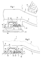
- the connecting means 12 are arranged to ensure, between the inertial unit 11 and the shoe 1, a mechanical coupling when the boot is not resting against the ground ( figure 1 ) and a mechanical decoupling when the boot is resting against the ground so that the inertial unit 11 is substantially immobile in relation to the ground when the shoe is resting against the ground ( figure 2 ).
- the connecting means 12 comprise a support 14 defining a housing 15 receiving the inertial unit 11 vertical sliding and having a lower surface 16 intended to extend facing the ground when the shoe is in position. support against the ground.
- the lower surface 16 constitutes a bearing surface of the support 14 against the ground.
- the housing 15 opens on the lower surface 16 to allow contact between the inertial unit 14 and the ground.
- the support 14 is housed in the heel 4 of the boot 1 and forms here a portion of the heel 4.
- the connecting means 12 comprise an inextensible flexible yarn 17 extending in a duct 18 of the support 14 and having one end attached to the inertial unit 11 and opposite one end attached to a counterweight 19 vertically slidably received in the support 11 between a projecting position of the lower surface 16 of the support 14 to bear on the ground and a depressed position.
- a return member 20 resiliently biasing the counterweight 19 in its projecting downward position.
- the return member 20 may be a helical compression spring or a layer of elastomeric material.
- the flexible wire 17 has a length such that the wire is stretched when the shoe is off the ground and loose when the shoe is resting against the ground.
- the counterweight 19 is projecting from the lower surface 16 and the inertial unit 11 is applied against the bottom of the housing 15 (flexible wire 17 stretched) and, when the boot is in abutment against the ground, the lower surface 16, the counterweight 19 and the inertial unit 11 are placed on the ground (loose flexible thread).
- the bottom of the housing 15 and the upper part of the inertial unit 11 preferably comprise reliefs of complementary shape to ensure a connection of the inertial unit 11 with the bottom of the housing 15 under the effect of the tension of the flexible wire 17.
- These reliefs here comprise conical bulges 21 formed on the upper surface of the inertial unit 11 to cooperate with conical recesses 22 formed in the bottom of the housing 15.
- the cap 23 to come under the heel 4 and protect the inertial device 10 when the user walks outside.
- the cap provides a seal sufficient to prevent the introduction of moisture or dirt into the housing receiving the inertial unit 11 and the counterweight 19.
- the inertial unit is also preferably dust and moisture-proof.
- the support 14 is independent of the sole 3 of the shoe 1 and is provided with temporary attachment means 24 to the sole.
- the temporary fixing means 24 are for example self-adhesive or self-gripping means such as those of the VELCRO brand.
- the inertial navigation device 10 is attached to the rear of the heel 4 and, at the figure 4 , on the side of the heel 4.
- the shoe 1 incorporates an inertial navigation device 10 which comprises a support 14 forming the heel of the sole 3 of the boot 1.
- the support 14 defines a housing 15 receiving the inertial unit 11 vertically sliding and has a lower surface 16.1 intended to extend facing the ground when the shoe is resting against the ground.
- the lower surface 16.1 here constitutes a bearing surface of the support 14 against the ground.
- the housing 15 opens on the lower surface 16.1 to allow contact between the inertial unit 11 and the ground.
- a rigid plate 25 closes the housing 15 and the inertial unit 11 is secured to the upper surface of the rigid plate 25.
- a flexible portion 26 is disposed between the support 11 and the rigid plate 25 which is integral with the inertial unit 11.
- the flexible portion 26 here has the shape of an elastically deformable sleeve surrounding the inertial unit 11.
- the flexible portion 26 is thus arranged to recall the rigid plate 25 projecting from the lower surface 16 and to limit the transmission to the inertial unit 11 of movements of the boot when the boot is resting against the ground.
- the lower surface 16.2 of the rigid plate 25 bears against the ground, the support force of the shoe on the ground is taken up by the support 14 and the flexible portion 26 decouples the inertial unit of the support and therefore of the shoe by limiting the transmission to the inertial unit 11 of movements of the shoe 1.
- a walking stick 30 whose lower end 31 is provided with an inertial navigation device 10 in all respects similar to that of the first embodiment.
- the support 14 here forms the support tip on the floor of the stick.
- the invention is applicable to any object intended to come intermittently in abutment with a surface and more particularly the ground.
- the device of the third embodiment is also usable to bear on a wall or other non-horizontal surface, gravity not involved in the decoupling.
- the flexible wire may have an end fixed to the bottom of the housing 15 and an end attached to the inertial unit 11.
- the flexible wire has a length such that it is loose when the lower face of the inertial unit 11 is flush with the lower surface 16 and extended when the inertial unit 11 is projecting from the lower surface 16.
- An elastic return member is preferably interposed between the bottom of the housing 15 and the inertial unit 11 to push the inertial unit 11 projecting from the lower surface 16.
- a fixed rigid plate can close the housing 15 and the inertial unit can be connected to the support 11 to bear against the rigid plate only when the shoe is placed on the ground.
- the inertial unit may comprise a different number of gyrometers and accelerometers.
- the digital terminal 13 may comprise a braille display and / or give voice or voice and / or visual indications.
- the navigation is optional, the invention can be used only to locate the wearer of the device.
- the flexible yarn may have some stretch as long as it does not prevent the loose thread when the counterweight and the inertial unit are placed on the ground and the wire taut when they are off the ground.
Landscapes
- Engineering & Computer Science (AREA)
- Radar, Positioning & Navigation (AREA)
- Remote Sensing (AREA)
- Physics & Mathematics (AREA)
- General Physics & Mathematics (AREA)
- Automation & Control Theory (AREA)
- Footwear And Its Accessory, Manufacturing Method And Apparatuses (AREA)
- Navigation (AREA)
Description
- La présente invention concerne un dispositif inertiel de localisation. L'invention s'adresse plus particulièrement à la navigation de personnes ignorant la topographie des lieux dans lesquels ils se trouvent et ne pouvant ou ne souhaitant pas utiliser la vue comme organe principal de repérage. L'invention peut ainsi être utilisée par les personnes malvoyantes. L'invention concerne également une chaussure et un équipement de la personne pourvus d'un tel dispositif.
- Dans le domaine de l'aide à la navigation de personne, il est connu d'utiliser des systèmes de navigation par satellites de type GPS (de l'anglais « Global Positioning System » pour système de positionnement global) ou « GALILEO ». Ces systèmes requièrent que l'utilisateur porte un récepteur de signaux satellitaires qui incorpore une unité de calcul agencée pour calculer la position du récepteur à partir des signaux satellitaires. Associés à un logiciel cartographique; ces systèmes sont particulièrement efficaces. Toutefois, il n'est pas possible de capter les signaux satellitaires dans certains environnements et notamment à l'intérieur de certains bâtiments et par exemple dans le métro.
- Les systèmes de navigation dédiés à la navigation à l'intérieur des bâtiments nécessitent que les bâtiments soient pré-équipés pour permettre un repérage par triangulation d'un dispositif porté par l'utilisateur. Ceci oblige l'utilisateur à cantonner ses déplacements dans les lieux qu'il sait équipés. En outre, les investissements à prévoir dissuadent généralement les organismes en charge de l'administration de ces bâtiments d'installer de tels systèmes.
- La navigation des utilisateurs dans les bâtiments reste ainsi généralement assistée uniquement par une signalétique de guidage et de repérage. Ce mode d'assistance à la navigation est interdit aux personnes malvoyantes et nécessite des conditions de luminosité pas toujours adaptées aux circonstances (panne d'électricité par exemple).
- Il a donc été proposé un système de navigation au moyen d'un dispositif inertiel comprenant une centrale inertielle comportant des gyromètres et des accéléromètres, et des moyens de liaison mécanique de la centrale inertielle à l'utilisateur. Connaissant le point de départ de l'utilisateur, comme l'entrée du bâtiment, il est possible de déterminer la trajectoire de l'utilisateur dans le bâtiment en intégrant les signaux d'accélération et de vitesse de rotation transmis par la centrale inertielle. Les résultats de ces systèmes de navigation se sont révélés encourageants malgré une relativement grande imprécision rendant difficile la navigation dans les bâtiments ayant un réseau de voies de circulation d'importante densité.
- Une majeure partie de cette imprécision résulte de la dérive permanente des capteurs en particulier lorsque ceux-ci sont des capteurs bas de gamme à faible coût. Pour limiter les effets de cette dérive sur le calcul de la trajectoire, il a été envisagé de fixer la centrale inertielle sur un pied de l'utilisateur de manière à stopper l'intégration des signaux lorsque le pied est au sol. Ceci permet en outre de recaler certains paramètres de fonctionnement lorsque le pied est au sol, comme le recalage du repère de la centrale inertielle sur le repère terrestre. La précision du système a ainsi été améliorée de façon significative.
US 2009/0071805 décrit un tel système, dans lequel un capteur placé dans la semelle de la chaussure détecte la partie stationnaire du pas de l'utilisateur (pose) - Un but de l'invention est de proposer un moyen pour améliorer encore la précision de ces systèmes en limitant les causes de perturbation externes au capteur.
- On s'est aperçu que le pied n'est jamais complètement immobile pendant les phases de pose :
- lorsque le pied est posé sur le sol, il peut être animé de petits mouvements, pour certains imperceptibles à l'oeil nu, transmis à la chaussure. Ces mouvements sont nécessaires à la marche et sont généralement incontrôlables. Ces mouvements entraînent une erreur qu'il est nécessaire de corriger et la correction logicielle d'une telle erreur n'est pas possible car cette erreur n'est pas quantifiable ni prédictible.
- Pour remédier à cet inconvénient, on prévoit, selon l'invention, un dispositif inertiel de navigation destiné à équiper un objet en appui intermittent avec une surface, le dispositif comprenant une centrale inertielle comportant au moins un capteur inertiel, et des moyens de liaison mécanique de la centrale inertielle à l'objet. Les moyens de liaison sont agencés pour assurer, entre la centrale inertielle et l'objet, un couplage mécanique lorsque l'objet n'est pas en appui contre la surface et un découplage mécanique lorsque l'objet est en appui contre la surface de telle manière que la centrale inertielle soit sensiblement immobile par rapport à la surface lorsque l'objet est en appui contre la surface.
- La surface est par exemple le sol. L'objet en question, en particulier lorsqu'il est tenu ou porté par un utilisateur comme par exemple une chaussure, peut bouger sous l'action volontaire ou involontaire de l'utilisateur lorsqu'il est en contact avec le sol. L'invention permet de limiter la transmission de ces mouvements à la centrale inertielle lors des phases d'appui contre le sol tout en assurant la transmission des mouvements de l'objet lorsque l'objet est en déplacement par rapport au sol. Ceci permet d'avoir une immobilité de la centrale la plus longue possible lors des phases d'appui de l'objet contre le sol.
- De préférence, les moyens de liaison comprennent un support définissant un logement recevant la centrale inertielle à coulissement vertical et ayant une surface inférieure destinée à s'étendre en regard de la surface lorsque l'objet est en appui contre la surface et, avantageusement, la surface inférieure constitue une surface d'appui du support contre la surface.
- Le support peut assurer une protection de la centrale inertielle et facilite la fixation ou l'intégration du dispositif inertiel à l'objet.
- Selon deux modes de réalisation alternatifs :
- le logement de réception de la centrale inertielle débouche sur la surface inférieure pour permettre une mise en contact de la centrale inertielle avec la surface.
- la surface inférieure appartient à une plaque rigide fermant le logement de réception de la centrale inertielle, la centrale inertielle venant en appui contre la plaque rigide au moins lorsque la plaque rigide est en contact avec la surface.
- La centrale inertielle est ainsi directement en contact avec le sol ou par l'intermédiaire d'une plaque rigide tandis que le support reprend l'effort d'appui du dispositif contre le sol.
- Selon un mode de réalisation préférentiel, les moyens de liaison comprennent un fil souple reliant la centrale inertielle au support et ayant une longueur telle que le fil est tendu lorsque l'objet est décollé de la surface et lâche lorsque l'objet est en appui contre la surface et, avantageusement, le fil s'étend dans un conduit et comporte une extrémité attachée à la centrale inertielle et à l'opposé une extrémité attachée à un contrepoids reçu à coulissement vertical dans le support entre une position en saillie de la surface inférieure du support pour prendre appui sur la surface et une position enfoncée.
- Le fil a une longueur adaptée pour à la fois entraîner la centrale inertielle pendant les phases de « vol » où l'objet est décollé du sol et maximiser la durée d'immobilisation de la centrale inertielle lors des phases d'appui de l'objet contre le sol.
- L'invention a également pour objet une chaussure dans laquelle le support forme une partie de la semelle et un équipement de la personne, comme une canne, un déambulateur ou un bâton de marche, équipé d'un dispositif de navigation conforme à l'invention.
- D'autres caractéristiques et avantages de l'invention ressortiront à la lecture de la description qui suit de modes de réalisation particuliers non limitatifs de l'invention.
- Il sera fait références aux dessins annexés, parmi lesquels :
- la
figure 1 est une vue schématique en coupe longitudinale d'une chaussure équipée d'un dispositif conforme à un premier mode de réalisation de l'invention, la chaussure étant décollée du sol, - la
figure 2 est une vue analogue à lafigure 1 de cette chaussure appliquée contre le sol, - la
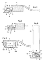
figure 3 est une vue analogue à lafigure 1 d'une chaussure équipée d'un dispositif conforme à un deuxième mode de réalisation de l'invention, - la
figure 4 est une vue schématique en coupe transversale d'une chaussure équipée de ce dispositif, lafigure 4 illustrant une variante de positionnement du dispositif, - la
figure 5 est une vue analogue à lafigure 1 d'une chaussure équipée d'un dispositif selon un troisième mode de réalisation de l'invention, - la
Figure 6 est une vue schématique partielle d'un bâton de marche équipé du dispositif conforme au deuxième mode de réalisation. - En référence aux
figures 1 à 5 , l'invention est décrite en application à une chaussure 1 comportant une tige 2 et une semelle 3 dont la partie arrière est conformée en talon 4 surélevé. - La chaussure 1 incorpore un dispositif inertiel de navigation 10 comprenant une centrale inertielle 11 et des moyens de liaison mécanique 12 de la centrale inertielle 11 à la chaussure 1.
- La centrale inertielle 11 comprend de façon connue en soi des gyromètres et des accéléromètres reliés à une unité de calcul elle-même reliée à une batterie d'alimentation et à un émetteur récepteur permettant une liaison sans fil (de préférence hertzienne) de l'unité de calcul avec un terminal numérique 13 intégrant un programme de calcul de trajectoire et un logiciel de cartographie. L'unité de calcul est agencée pour récupérer les signaux en provenance des gyromètres et des accéléromètres et effectuer un traitement de ceux-ci de manière à pouvoir communiquer au terminal numérique 13 des données lui permettant de déterminer la trajectoire suivie par la centrale inertielle 11. Le terminal numérique 13 est du type assistant personnel numérique (ou PDA) et le logiciel de cartographie permet de reporter la trajectoire calculée dans une carte des lieux mémorisée dans le terminal et de déterminer un itinéraire à suivre pour rejoindre un point d'arrivée préprogrammé. Le terminal numérique 13 comprend en outre un programme de synthèse vocale lui permettant de communiquer vocalement à l'utilisateur l'itinéraire à suivre.
- Les moyens de liaison 12 sont agencés pour assurer, entre la centrale inertielle 11 et la chaussure 1, un couplage mécanique lorsque la chaussure n'est pas en appui contre le sol (
figure 1 ) et un découplage mécanique lorsque la chaussure est en appui contre le sol de telle manière que la centrale inertielle 11 soit sensiblement immobile par rapport au sol lorsque la chaussure est en appui contre le sol (figure 2 ). - En référence plus particulièrement aux
figures 1 et 2 , et selon le premier mode de réalisation, les moyens de liaison 12 comprennent un support 14 définissant un logement 15 recevant la centrale inertielle 11 à coulissement vertical et ayant une surface inférieure 16 destinée à s'étendre en regard du sol lorsque la chaussure est en appui contre le sol. La surface inférieure 16 constitue une surface d'appui du support 14 contre le sol. Le logement 15 débouche sur la surface inférieure 16 pour permettre une mise en contact de la centrale inertielle 14 avec le sol. Le support 14 est logé dans le talon 4 de la chaussure 1 et forme ici une partie du talon 4. - Les moyens de liaison 12 comprennent un fil souple 17 inextensible s'étendant dans un conduit 18 du support 14 et comportant une extrémité attachée à la centrale inertielle 11 et à l'opposé une extrémité attachée à un contrepoids 19 reçu à coulissement vertical dans le support 11 entre une position en saillie de la surface inférieure 16 du support 14 pour prendre appui sur le sol et une position enfoncée. Un organe de rappel 20 rappel élastiquement le contrepoids 19 dans sa position descendue en saillie. L'organe de rappel 20 peut être un ressort hélicoïdal de compression ou une couche de matériau élastomère. Le fil souple 17 a une longueur telle que le fil est tendu lorsque la chaussure est décollée du sol et lâche lorsque la chaussure est en appui contre le sol. Ainsi, lorsque la chaussure est décollée du sol, le contrepoids 19 est en saillie de la surface inférieure 16 et la centrale inertielle 11 est appliquée contre le fond du logement 15 (fil souple 17 tendu) et, lorsque la chaussure est en appui contre le sol, la surface inférieure 16, le contrepoids 19 et la centrale inertielle 11 sont posés au sol (fil souple lâche).
- Le fond du logement 15 et la partie supérieure de la centrale inertielle 11 comprennent de préférence des reliefs de forme complémentaire pour assurer une solidarisation de la centrale inertielle 11 avec le fond du logement 15 sous l'effet de la tension du fil souple 17. Ces reliefs comprennent ici des bombés coniques 21 ménagés sur la surface supérieure de la centrale inertielle 11 pour coopérer avec des renfoncements coniques 22 ménagés dans le fond du logement 15. Ces reliefs assurent ici notamment une solidarisation en rotation de la centrale inertielle avec le support 11 autour d'un axe du logement 15.
- Il est prévu un capuchon 23 pour venir se mettre sous le talon 4 et protéger le dispositif inertiel 10 lorsque l'utilisateur marche à l'extérieur. Le capuchon assure une étanchéité suffisante pour empêcher l'introduction d'humidité ou de salissures dans les logements recevant la centrale inertielle 11 et le contrepoids 19. La centrale inertielle est également de préférence étanche aux poussières et à l'humidité.
- En référence aux
figures 3 et 4 et selon le deuxième mode de réalisation, le support 14 est indépendant de la semelle 3 de la chaussure 1 et est pourvu de moyens de fixation temporaire 24 à la semelle. Les moyens de fixation temporaire 24 sont par exemple des moyens autocollants ou auto-agrippants tels que ceux de la marque VELCRO. - A la
figure 3 , le dispositif inertiel de navigation 10 est fixé à l'arrière du talon 4 et, à lafigure 4 , sur le côté du talon 4. - Dans le troisième mode de réalisation de la
figure 5 , la chaussure 1 incorpore un dispositif inertiel de navigation 10 qui comporte un support 14 formant le talon de la semelle 3 de la chaussure 1. Le support 14 définit un logement 15 recevant la centrale inertielle 11 à coulissement vertical et possède une surface inférieure 16.1 destinée à s'étendre en regard du sol lorsque la chaussure est en appui contre le sol. La surface inférieure 16.1 constitue ici une surface d'appui du support 14 contre le sol. Le logement 15 débouche sur la surface inférieure 16.1 pour permettre une mise en contact de la centrale inertielle 11 avec le sol. - Une plaque rigide 25 ferme le logement 15 et la centrale inertielle 11 est solidaire de la surface supérieure de la plaque rigide 25.
- Une portion souple 26 est disposée entre le support 11 et la plaque rigide 25 dont est solidaire la centrale inertielle 11. La portion souple 26 a ici la forme d'un manchon élastiquement déformable entourant la centrale inertielle 11. La partie souple 26 est ainsi agencée pour rappeler la plaque rigide 25 en saillie de la surface inférieure 16 et pour limiter la transmission à la centrale inertielle 11 de mouvements de la chaussure lorsque la chaussure est en appui contre le sol. Lorsque la chaussure est en appui contre le sol, la surface inférieure 16.2 de la plaque rigide 25 est en appui contre le sol, l'effort d'appui de la chaussure sur le sol est repris par le support 14 et la portion souple 26 découple la centrale inertielle du support et donc de la chaussure en limitant la transmission à la centrale inertielle 11 de mouvements de la chaussure 1.
- A la
figure 6 , est représenté un bâton de marche 30 dont l'extrémité inférieure 31 est pourvue d'un dispositif inertiel de navigation 10 en tout point semblable à celui du premier mode de réalisation. Le support 14 forme ici l'embout d'appui sur le sol du bâton. - Bien entendu, l'invention n'est pas limitée aux modes de réalisation décrits mais englobe toute variante entrant dans le champ de l'invention telle que définie par les revendications.
- En particulier, l'invention est applicable à tout objet destiné à venir de manière intermittente en appui avec une surface et plus particulièrement le sol.
- Le dispositif du troisième mode de réalisation est aussi utilisable pour prendre appui sur un mur ou tout autre surface non horizontale, la gravité n'intervenant pas dans le découplage.
- Le fil souple peut avoir une extrémité fixée au fond du logement 15 et une extrémité attachée à la centrale inertielle 11. Le fil souple a une longueur telle qu'il est lâche lorsque la face inférieure de la centrale inertielle 11 affleure la surface inférieure 16 et tendu lorsque la centrale inertielle 11 est en saillie de la surface inférieure 16. Un organe de rappel élastique est de préférence interposé entre le fond du logement 15 et la centrale inertielle 11 pour repousser la centrale inertielle 11 en saillie de la surface inférieure 16.
- Une plaque rigide fixe peut fermer le logement 15 et la centrale inertielle peut être reliée au support 11 pour venir en appui de la plaque rigide seulement lorsque la chaussure est posée au sol.
- La centrale inertielle peut comprendre un nombre différent de gyromètres et d'accéléromètres.
- Le terminal numérique 13 peut comprendre un afficheur braille et/ou donner des indications sonores ou vocales et/ou visuelles.
- On notera que la navigation est optionnelle, l'invention pouvant être utilisée uniquement pour localiser le porteur du dispositif.
- Le fil souple peut présenter une certaine extensibilité tant que celle-ci n'empêche pas d'avoir le fil lâche lorsque le contrepoids et la centrale inertielle sont posés au sol et le fil tendu lorsque ceux-ci sont décollés du sol.
Claims (10)
- Dispositif inertiel de navigation (10) destiné à équiper un objet (1) en appui intermittent avec une surface, le dispositif comprenant une centrale inertielle (11) comportant au moins un capteur inertiel, et des moyens de liaison mécanique de la centrale inertielle à l'objet (12), caractérisé en ce que les moyens de liaison (12) sont agencés pour assurer, entre la centrale inertielle (11) et l'objet (11), un couplage mécanique lorsque l'objet (1) n'est pas en appui contre la surface et un découplage mécanique lorsque l'objet (1) est en appui contre la surface de telle manière que la centrale inertielle (11) soit sensiblement immobile par rapport à la surface lorsque l'objet est en appui contre la surface.
- Dispositif selon la revendication 1, dans lequel les moyens de liaison (12) comprennent un support (14) définissant un logement (15) recevant la centrale inertielle (11) à coulissement vertical et ayant une surface inférieure (16) destinée à s'étendre en regard du sol lorsque l'objet (1) est en appui contre la surface.
- Dispositif selon la revendication 2, dans lequel la surface inférieure (16) constitue une surface d'appui du support contre la surface.
- Dispositif selon la revendication 3, dans lequel le logement (14) de réception de la centrale inertielle (11) débouche sur la surface inférieure (14) pour permettre une mise en contact de la centrale inertielle (11) avec la surface.
- Dispositif selon la revendication 3, dans lequel la surface inférieure (16) appartient à une plaque rigide (25) fermant le logement de réception de la centrale inertielle (11), la centrale inertielle (11) venant en appui contre la plaque rigide (25) au moins lorsque la plaque rigide (25) est en contact avec la surface.
- Dispositif selon l'une quelconque revendication 2 à 5, dans lequel les moyens de liaison (12) comprennent un fil souple (17) reliant la centrale inertielle (11) au support (14) et ayant une longueur telle que le fil est tendu lorsque l'objet (1) est décollé du sol et lâche lorsque l'objet (1) est en appui contre la surface.
- Dispositif selon la revendication 6, dans lequel le fil (17) s'étend dans un conduitvet comporte une extrémité attachée à la centrale inertielle (11) et à l'opposé une extrémité attachée à un contrepoids (19) reçu à coulissement vertical dans le support (14) entre une position en saillie de la surface inférieure (16) du support pour prendre appui sur la surface et une position enfoncée.
- Dispositif selon l'une quelconque des revendications 2 à 5, dans lequel le support (14) comporte une portion souple (26) disposée entre le support (14) et la centrale inertielle (11) et agencée pour limiter la transmission à la centrale inertielle (11) de mouvements de l'objet (1) lorsque l'objet (1) est en appui contre la surface.
- Chaussure ayant une semelle équipée d'un dispositif conforme à l'une quelconque des revendications 2 à 8, dans laquelle le support (14) forme une partie de la semelle.
- Equipement de la personne, l'équipement étant pourvu d'un dispositif conforme à l'une quelconque des revendications 1 à 8.
Applications Claiming Priority (2)
| Application Number | Priority Date | Filing Date | Title |
|---|---|---|---|
| FR0902421A FR2945864B1 (fr) | 2009-05-19 | 2009-05-19 | Dispositif inertiel de localisation, chaussure et equipement de la personne pourvus d'un tel dispositif |
| PCT/EP2010/056743 WO2010133553A1 (fr) | 2009-05-19 | 2010-05-17 | Dispositif inertiel de localisation, chaussure et equipement de la personne pourvus d'un tel dispositif |
Publications (2)
| Publication Number | Publication Date |
|---|---|
| EP2433095A1 EP2433095A1 (fr) | 2012-03-28 |
| EP2433095B1 true EP2433095B1 (fr) | 2013-04-03 |
Family
ID=41398942
Family Applications (1)
| Application Number | Title | Priority Date | Filing Date |
|---|---|---|---|
| EP10722047A Not-in-force EP2433095B1 (fr) | 2009-05-19 | 2010-05-17 | Dispositif inertiel de localisation, chaussure et equipement de la personne pourvus d'un tel dispositif |
Country Status (5)
| Country | Link |
|---|---|
| US (1) | US8756993B2 (fr) |
| EP (1) | EP2433095B1 (fr) |
| ES (1) | ES2413084T3 (fr) |
| FR (1) | FR2945864B1 (fr) |
| WO (1) | WO2010133553A1 (fr) |
Families Citing this family (2)
| Publication number | Priority date | Publication date | Assignee | Title |
|---|---|---|---|---|
| WO2017120063A1 (fr) * | 2016-01-04 | 2017-07-13 | Sensoria Inc. | Article chaussant intégrant des capteurs, capteurs, interfaces et systèmes de capteurs pour collecter des données |
| US10758161B2 (en) | 2015-03-27 | 2020-09-01 | Firefly Medical, Inc. | Patient mobility assessment device |
Family Cites Families (12)
| Publication number | Priority date | Publication date | Assignee | Title |
|---|---|---|---|---|
| US6266623B1 (en) * | 1994-11-21 | 2001-07-24 | Phatrat Technology, Inc. | Sport monitoring apparatus for determining loft time, speed, power absorbed and other factors such as height |
| US6122340A (en) * | 1998-10-01 | 2000-09-19 | Personal Electronic Devices, Inc. | Detachable foot mount for electronic device |
| US20030009308A1 (en) * | 2000-06-24 | 2003-01-09 | Chris Kirtley | Instrumented insole |
| US6836744B1 (en) * | 2000-08-18 | 2004-12-28 | Fareid A. Asphahani | Portable system for analyzing human gait |
| US7225565B2 (en) * | 2003-03-10 | 2007-06-05 | Adidas International Marketing B.V. | Intelligent footwear systems |
| US7631382B2 (en) * | 2003-03-10 | 2009-12-15 | Adidas International Marketing B.V. | Intelligent footwear systems |
| US7607243B2 (en) * | 2006-05-03 | 2009-10-27 | Nike, Inc. | Athletic or other performance sensing systems |
| JP2008268098A (ja) * | 2007-04-24 | 2008-11-06 | Aruze Corp | 携帯ナビゲーション装置 |
| US7943874B2 (en) * | 2007-09-18 | 2011-05-17 | Honeywell International Inc. | Ground contact switch for personal navigation system |
| KR20110071728A (ko) * | 2009-12-21 | 2011-06-29 | 한국전자통신연구원 | 인솔형 네비게이션 장치 및 그 동작 방법 |
| CN102835771A (zh) * | 2012-09-28 | 2012-12-26 | 西安西达地质技术服务有限责任公司 | 一种野外导航鞋 |
| CN102871285A (zh) * | 2012-10-15 | 2013-01-16 | 南通奥斯特鞋业有限公司 | 一种改进的高跟鞋 |
-
2009
- 2009-05-19 FR FR0902421A patent/FR2945864B1/fr not_active Expired - Fee Related
-
2010
- 2010-05-17 WO PCT/EP2010/056743 patent/WO2010133553A1/fr not_active Ceased
- 2010-05-17 EP EP10722047A patent/EP2433095B1/fr not_active Not-in-force
- 2010-05-17 ES ES10722047T patent/ES2413084T3/es active Active
- 2010-05-17 US US13/318,381 patent/US8756993B2/en not_active Expired - Fee Related
Also Published As
| Publication number | Publication date |
|---|---|
| US20120060393A1 (en) | 2012-03-15 |
| FR2945864A1 (fr) | 2010-11-26 |
| US8756993B2 (en) | 2014-06-24 |
| WO2010133553A1 (fr) | 2010-11-25 |
| ES2413084T3 (es) | 2013-07-15 |
| EP2433095A1 (fr) | 2012-03-28 |
| FR2945864B1 (fr) | 2011-05-13 |
Similar Documents
| Publication | Publication Date | Title |
|---|---|---|
| EP3359915B1 (fr) | Procédé d'estimation du mouvement d'un piéton | |
| EP1984696B1 (fr) | Dispositif de capture de mouvement et procede associe | |
| EP3139348B1 (fr) | Procede et systeme de mesure d'un temps de reaction au depart d'une course | |
| EP3116691A1 (fr) | Chausson d'exosquelette | |
| FR2943869A1 (fr) | Procede et dispositif de detection et d'exclusion de pannes satellite dans un systeme hybride ins/gnss | |
| CA2644462A1 (fr) | Procede et dispositif de positionnement hybride | |
| EP2449409B1 (fr) | Procede de determination de la position d'un mobile a un instant donne et de surveillance de l'integrite de la position dudit mobile. | |
| EP2433095B1 (fr) | Dispositif inertiel de localisation, chaussure et equipement de la personne pourvus d'un tel dispositif | |
| FR2944888A1 (fr) | Procede d'aide a la navigation pour la determination de la trajectoire d'un aeronef | |
| EP3139349B1 (fr) | Procede et systeme de mesure ou de prediction d'un temps de course de haies | |
| EP2223047B1 (fr) | Procede d'alignement autonome d'unite de mesure inertielle pour instrument de bord d'aeronef. | |
| EP3724605B1 (fr) | Procédé d'estimation de données de navigation d'un véhicule terrestre utilisant des paramètres de géométrie et d'orientation de route | |
| EP2953694B1 (fr) | Fixation sécurisée de chaussure sur un ski | |
| WO2010070011A1 (fr) | Dispositif d'hybridation a filtres de kalman segreges | |
| EP3137176A1 (fr) | Dispositif de fixation securisee d'une chaussure sur un ski | |
| EP3479291A1 (fr) | Capteur, systeme d'analyse statistique et procede de determination et d'affichage de la hauteur d'un saut effectue par un sportif | |
| EP3292894B1 (fr) | Dispositif de mesure de l orientation de deux skis ou deux chaussures de ski | |
| FR3053954B1 (fr) | Pedale intuitive | |
| FR2939191A1 (fr) | Dispositif et procede d'assistance au guidage d'un pieton en difficulte de perception visuelle, telle qu'une personne aveugle | |
| Norman | Kierkegaard: la polysémie de | |
| FR3039890A1 (fr) | Dispositif de mesure de l'orientation de deux skis ou deux chaussures de ski | |
| CA3012403C (fr) | Procede d'estimation de l'activite physique d'un membre superieur | |
| Dez | Synode d'Aunis de 1777 | |
| CH703020A2 (fr) | Système pérenne de localisation 3D d'un individu en progression à l'intérieur d'un bâtiment. | |
| FR3057071A1 (fr) | Procede de localisation hybride d'un pieton |
Legal Events
| Date | Code | Title | Description |
|---|---|---|---|
| PUAI | Public reference made under article 153(3) epc to a published international application that has entered the european phase |
Free format text: ORIGINAL CODE: 0009012 |
|
| 17P | Request for examination filed |
Effective date: 20111019 |
|
| AK | Designated contracting states |
Kind code of ref document: A1 Designated state(s): AL AT BE BG CH CY CZ DE DK EE ES FI FR GB GR HR HU IE IS IT LI LT LU LV MC MK MT NL NO PL PT RO SE SI SK SM TR |
|
| RIN1 | Information on inventor provided before grant (corrected) |
Inventor name: RIWAN, ALAIN Inventor name: PETRES, CLEMENT Inventor name: LAMY-PERBAL, SYLVIE |
|
| DAX | Request for extension of the european patent (deleted) | ||
| GRAP | Despatch of communication of intention to grant a patent |
Free format text: ORIGINAL CODE: EPIDOSNIGR1 |
|
| RIN1 | Information on inventor provided before grant (corrected) |
Inventor name: PETRES, CLEMENT Inventor name: RIWAN, ALAIN Inventor name: LAMY-PERBAL, SYLVIE |
|
| GRAS | Grant fee paid |
Free format text: ORIGINAL CODE: EPIDOSNIGR3 |
|
| GRAA | (expected) grant |
Free format text: ORIGINAL CODE: 0009210 |
|
| AK | Designated contracting states |
Kind code of ref document: B1 Designated state(s): AL AT BE BG CH CY CZ DE DK EE ES FI FR GB GR HR HU IE IS IT LI LT LU LV MC MK MT NL NO PL PT RO SE SI SK SM TR |
|
| REG | Reference to a national code |
Ref country code: GB Ref legal event code: FG4D Free format text: NOT ENGLISH |
|
| REG | Reference to a national code |
Ref country code: CH Ref legal event code: EP Ref country code: AT Ref legal event code: REF Ref document number: 605006 Country of ref document: AT Kind code of ref document: T Effective date: 20130415 |
|
| REG | Reference to a national code |
Ref country code: IE Ref legal event code: FG4D Free format text: LANGUAGE OF EP DOCUMENT: FRENCH |
|
| REG | Reference to a national code |
Ref country code: DE Ref legal event code: R096 Ref document number: 602010005955 Country of ref document: DE Effective date: 20130529 |
|
| REG | Reference to a national code |
Ref country code: ES Ref legal event code: FG2A Ref document number: 2413084 Country of ref document: ES Kind code of ref document: T3 Effective date: 20130715 |
|
| REG | Reference to a national code |
Ref country code: AT Ref legal event code: MK05 Ref document number: 605006 Country of ref document: AT Kind code of ref document: T Effective date: 20130403 |
|
| PG25 | Lapsed in a contracting state [announced via postgrant information from national office to epo] |
Ref country code: SI Free format text: LAPSE BECAUSE OF FAILURE TO SUBMIT A TRANSLATION OF THE DESCRIPTION OR TO PAY THE FEE WITHIN THE PRESCRIBED TIME-LIMIT Effective date: 20130403 |
|
| REG | Reference to a national code |
Ref country code: NL Ref legal event code: VDEP Effective date: 20130403 |
|
| REG | Reference to a national code |
Ref country code: LT Ref legal event code: MG4D |
|
| PG25 | Lapsed in a contracting state [announced via postgrant information from national office to epo] |
Ref country code: LT Free format text: LAPSE BECAUSE OF FAILURE TO SUBMIT A TRANSLATION OF THE DESCRIPTION OR TO PAY THE FEE WITHIN THE PRESCRIBED TIME-LIMIT Effective date: 20130403 Ref country code: AT Free format text: LAPSE BECAUSE OF FAILURE TO SUBMIT A TRANSLATION OF THE DESCRIPTION OR TO PAY THE FEE WITHIN THE PRESCRIBED TIME-LIMIT Effective date: 20130403 Ref country code: FI Free format text: LAPSE BECAUSE OF FAILURE TO SUBMIT A TRANSLATION OF THE DESCRIPTION OR TO PAY THE FEE WITHIN THE PRESCRIBED TIME-LIMIT Effective date: 20130403 Ref country code: NO Free format text: LAPSE BECAUSE OF FAILURE TO SUBMIT A TRANSLATION OF THE DESCRIPTION OR TO PAY THE FEE WITHIN THE PRESCRIBED TIME-LIMIT Effective date: 20130703 Ref country code: PT Free format text: LAPSE BECAUSE OF FAILURE TO SUBMIT A TRANSLATION OF THE DESCRIPTION OR TO PAY THE FEE WITHIN THE PRESCRIBED TIME-LIMIT Effective date: 20130805 Ref country code: IS Free format text: LAPSE BECAUSE OF FAILURE TO SUBMIT A TRANSLATION OF THE DESCRIPTION OR TO PAY THE FEE WITHIN THE PRESCRIBED TIME-LIMIT Effective date: 20130803 Ref country code: NL Free format text: LAPSE BECAUSE OF FAILURE TO SUBMIT A TRANSLATION OF THE DESCRIPTION OR TO PAY THE FEE WITHIN THE PRESCRIBED TIME-LIMIT Effective date: 20130403 Ref country code: GR Free format text: LAPSE BECAUSE OF FAILURE TO SUBMIT A TRANSLATION OF THE DESCRIPTION OR TO PAY THE FEE WITHIN THE PRESCRIBED TIME-LIMIT Effective date: 20130704 Ref country code: SE Free format text: LAPSE BECAUSE OF FAILURE TO SUBMIT A TRANSLATION OF THE DESCRIPTION OR TO PAY THE FEE WITHIN THE PRESCRIBED TIME-LIMIT Effective date: 20130403 |
|
| PG25 | Lapsed in a contracting state [announced via postgrant information from national office to epo] |
Ref country code: CY Free format text: LAPSE BECAUSE OF FAILURE TO SUBMIT A TRANSLATION OF THE DESCRIPTION OR TO PAY THE FEE WITHIN THE PRESCRIBED TIME-LIMIT Effective date: 20130403 Ref country code: BG Free format text: LAPSE BECAUSE OF FAILURE TO SUBMIT A TRANSLATION OF THE DESCRIPTION OR TO PAY THE FEE WITHIN THE PRESCRIBED TIME-LIMIT Effective date: 20130703 Ref country code: HR Free format text: LAPSE BECAUSE OF FAILURE TO SUBMIT A TRANSLATION OF THE DESCRIPTION OR TO PAY THE FEE WITHIN THE PRESCRIBED TIME-LIMIT Effective date: 20130403 Ref country code: LV Free format text: LAPSE BECAUSE OF FAILURE TO SUBMIT A TRANSLATION OF THE DESCRIPTION OR TO PAY THE FEE WITHIN THE PRESCRIBED TIME-LIMIT Effective date: 20130403 Ref country code: PL Free format text: LAPSE BECAUSE OF FAILURE TO SUBMIT A TRANSLATION OF THE DESCRIPTION OR TO PAY THE FEE WITHIN THE PRESCRIBED TIME-LIMIT Effective date: 20130403 |
|
| BERE | Be: lapsed |
Owner name: COMMISSARIAT A L'ENERGIE ATOMIQUE ET AUX ENERGIES Effective date: 20130531 |
|
| PG25 | Lapsed in a contracting state [announced via postgrant information from national office to epo] |
Ref country code: SK Free format text: LAPSE BECAUSE OF FAILURE TO SUBMIT A TRANSLATION OF THE DESCRIPTION OR TO PAY THE FEE WITHIN THE PRESCRIBED TIME-LIMIT Effective date: 20130403 Ref country code: EE Free format text: LAPSE BECAUSE OF FAILURE TO SUBMIT A TRANSLATION OF THE DESCRIPTION OR TO PAY THE FEE WITHIN THE PRESCRIBED TIME-LIMIT Effective date: 20130403 Ref country code: DK Free format text: LAPSE BECAUSE OF FAILURE TO SUBMIT A TRANSLATION OF THE DESCRIPTION OR TO PAY THE FEE WITHIN THE PRESCRIBED TIME-LIMIT Effective date: 20130403 Ref country code: CZ Free format text: LAPSE BECAUSE OF FAILURE TO SUBMIT A TRANSLATION OF THE DESCRIPTION OR TO PAY THE FEE WITHIN THE PRESCRIBED TIME-LIMIT Effective date: 20130403 Ref country code: MC Free format text: LAPSE BECAUSE OF FAILURE TO SUBMIT A TRANSLATION OF THE DESCRIPTION OR TO PAY THE FEE WITHIN THE PRESCRIBED TIME-LIMIT Effective date: 20130403 |
|
| PLBE | No opposition filed within time limit |
Free format text: ORIGINAL CODE: 0009261 |
|
| STAA | Information on the status of an ep patent application or granted ep patent |
Free format text: STATUS: NO OPPOSITION FILED WITHIN TIME LIMIT |
|
| REG | Reference to a national code |
Ref country code: IE Ref legal event code: MM4A |
|
| PG25 | Lapsed in a contracting state [announced via postgrant information from national office to epo] |
Ref country code: RO Free format text: LAPSE BECAUSE OF FAILURE TO SUBMIT A TRANSLATION OF THE DESCRIPTION OR TO PAY THE FEE WITHIN THE PRESCRIBED TIME-LIMIT Effective date: 20130403 Ref country code: BE Free format text: LAPSE BECAUSE OF NON-PAYMENT OF DUE FEES Effective date: 20130531 |
|
| 26N | No opposition filed |
Effective date: 20140106 |
|
| REG | Reference to a national code |
Ref country code: DE Ref legal event code: R097 Ref document number: 602010005955 Country of ref document: DE Effective date: 20140106 |
|
| PG25 | Lapsed in a contracting state [announced via postgrant information from national office to epo] |
Ref country code: IE Free format text: LAPSE BECAUSE OF NON-PAYMENT OF DUE FEES Effective date: 20130517 |
|
| PGFP | Annual fee paid to national office [announced via postgrant information from national office to epo] |
Ref country code: GB Payment date: 20140521 Year of fee payment: 5 |
|
| PGFP | Annual fee paid to national office [announced via postgrant information from national office to epo] |
Ref country code: DE Payment date: 20140521 Year of fee payment: 5 Ref country code: ES Payment date: 20140528 Year of fee payment: 5 Ref country code: FR Payment date: 20140527 Year of fee payment: 5 Ref country code: IT Payment date: 20140523 Year of fee payment: 5 |
|
| REG | Reference to a national code |
Ref country code: CH Ref legal event code: PL |
|
| PG25 | Lapsed in a contracting state [announced via postgrant information from national office to epo] |
Ref country code: LI Free format text: LAPSE BECAUSE OF NON-PAYMENT OF DUE FEES Effective date: 20140531 Ref country code: CH Free format text: LAPSE BECAUSE OF NON-PAYMENT OF DUE FEES Effective date: 20140531 |
|
| PG25 | Lapsed in a contracting state [announced via postgrant information from national office to epo] |
Ref country code: MT Free format text: LAPSE BECAUSE OF FAILURE TO SUBMIT A TRANSLATION OF THE DESCRIPTION OR TO PAY THE FEE WITHIN THE PRESCRIBED TIME-LIMIT Effective date: 20130403 |
|
| REG | Reference to a national code |
Ref country code: DE Ref legal event code: R082 Ref document number: 602010005955 Country of ref document: DE Representative=s name: SCHAUMBURG & PARTNER PATENTANWAELTE GBR, DE Ref country code: DE Ref legal event code: R082 Ref document number: 602010005955 Country of ref document: DE Representative=s name: SCHAUMBURG & PARTNER PATENTANWAELTE MBB, DE |
|
| PG25 | Lapsed in a contracting state [announced via postgrant information from national office to epo] |
Ref country code: SM Free format text: LAPSE BECAUSE OF FAILURE TO SUBMIT A TRANSLATION OF THE DESCRIPTION OR TO PAY THE FEE WITHIN THE PRESCRIBED TIME-LIMIT Effective date: 20130403 |
|
| PG25 | Lapsed in a contracting state [announced via postgrant information from national office to epo] |
Ref country code: TR Free format text: LAPSE BECAUSE OF FAILURE TO SUBMIT A TRANSLATION OF THE DESCRIPTION OR TO PAY THE FEE WITHIN THE PRESCRIBED TIME-LIMIT Effective date: 20130403 |
|
| PG25 | Lapsed in a contracting state [announced via postgrant information from national office to epo] |
Ref country code: MK Free format text: LAPSE BECAUSE OF FAILURE TO SUBMIT A TRANSLATION OF THE DESCRIPTION OR TO PAY THE FEE WITHIN THE PRESCRIBED TIME-LIMIT Effective date: 20130403 Ref country code: LU Free format text: LAPSE BECAUSE OF NON-PAYMENT OF DUE FEES Effective date: 20130517 Ref country code: HU Free format text: LAPSE BECAUSE OF FAILURE TO SUBMIT A TRANSLATION OF THE DESCRIPTION OR TO PAY THE FEE WITHIN THE PRESCRIBED TIME-LIMIT; INVALID AB INITIO Effective date: 20100517 |
|
| REG | Reference to a national code |
Ref country code: DE Ref legal event code: R119 Ref document number: 602010005955 Country of ref document: DE |
|
| GBPC | Gb: european patent ceased through non-payment of renewal fee |
Effective date: 20150517 |
|
| PG25 | Lapsed in a contracting state [announced via postgrant information from national office to epo] |
Ref country code: IT Free format text: LAPSE BECAUSE OF NON-PAYMENT OF DUE FEES Effective date: 20150517 |
|
| REG | Reference to a national code |
Ref country code: FR Ref legal event code: ST Effective date: 20160129 |
|
| PG25 | Lapsed in a contracting state [announced via postgrant information from national office to epo] |
Ref country code: GB Free format text: LAPSE BECAUSE OF NON-PAYMENT OF DUE FEES Effective date: 20150517 Ref country code: DE Free format text: LAPSE BECAUSE OF NON-PAYMENT OF DUE FEES Effective date: 20151201 |
|
| PG25 | Lapsed in a contracting state [announced via postgrant information from national office to epo] |
Ref country code: FR Free format text: LAPSE BECAUSE OF NON-PAYMENT OF DUE FEES Effective date: 20150601 |
|
| REG | Reference to a national code |
Ref country code: ES Ref legal event code: FD2A Effective date: 20160628 |
|
| PG25 | Lapsed in a contracting state [announced via postgrant information from national office to epo] |
Ref country code: ES Free format text: LAPSE BECAUSE OF NON-PAYMENT OF DUE FEES Effective date: 20150518 |
|
| PG25 | Lapsed in a contracting state [announced via postgrant information from national office to epo] |
Ref country code: AL Free format text: LAPSE BECAUSE OF FAILURE TO SUBMIT A TRANSLATION OF THE DESCRIPTION OR TO PAY THE FEE WITHIN THE PRESCRIBED TIME-LIMIT Effective date: 20130403 |