EP2433487B1 - Element und Maschine zum Schneiden und Aufsammeln von Pflanzen, Arbeitsgerät, das ein solches Element oder eine solche Maschine enthält, und Verfahren zum Schneiden und Aufsammeln von Pflanzen - Google Patents
Element und Maschine zum Schneiden und Aufsammeln von Pflanzen, Arbeitsgerät, das ein solches Element oder eine solche Maschine enthält, und Verfahren zum Schneiden und Aufsammeln von Pflanzen Download PDFInfo
- Publication number
- EP2433487B1 EP2433487B1 EP11181431.5A EP11181431A EP2433487B1 EP 2433487 B1 EP2433487 B1 EP 2433487B1 EP 11181431 A EP11181431 A EP 11181431A EP 2433487 B1 EP2433487 B1 EP 2433487B1
- Authority
- EP
- European Patent Office
- Prior art keywords
- cutting
- pickup
- plants
- cutting member
- relative
- Prior art date
- Legal status (The legal status is an assumption and is not a legal conclusion. Google has not performed a legal analysis and makes no representation as to the accuracy of the status listed.)
- Not-in-force
Links
Images



Classifications
-
- A—HUMAN NECESSITIES
- A01—AGRICULTURE; FORESTRY; ANIMAL HUSBANDRY; HUNTING; TRAPPING; FISHING
- A01G—HORTICULTURE; CULTIVATION OF VEGETABLES, FLOWERS, RICE, FRUIT, VINES, HOPS OR SEAWEED; FORESTRY; WATERING
- A01G23/00—Forestry
- A01G23/02—Transplanting, uprooting, felling or delimbing trees
- A01G23/08—Felling trees
- A01G23/093—Combinations of shearing, sawing or milling apparatus specially adapted for felling trees
Definitions
- the present invention relates to a plant cutting and collecting element, a machine comprising two such elements, a working machine comprising such an element or such a machine and a method of cutting and collecting plants.
- the present invention is particularly applicable in the field of forestry.
- plant covers any plant consisting of roots which ensure its attachment to the soil, a stem or trunk and leaves or other parts that grow in the air.
- Patent publication EP 0 562 406 B1 discloses a plant cutting and picking member having a cutting member adapted to cut the plants when the cutting and picking member is moved in a forward direction of a back / front axle, a pickup system adapted for conveying the cut plants to an outlet of the cutting and picking member, and a drive system of the cutter and the pickup system.
- the plant is a small tree and the collection system comprises a support for maintaining the vertical shaft and a vertical propeller against which the cut tree is supported.
- the propeller drives the cut tree down (which is then the "output" of the collection system), and more precisely to a shredding blade for cutting the tree into shreds.
- the flaps are then evacuated by a chimney.
- the cutting member is a cutting disc advanced relative to the propeller and the chipping blade, so that the shaft is cut before being driven by the propeller.
- This known cutting and picking element nevertheless has the disadvantage of not being suitable for small plants, such as shrubs or scrub. Indeed, as the cutting disc is advanced, such plants are cut well before coming into contact with the system. pickup. In addition, these plants are too small to be held vertically by the support. Thus, the small plants collapse before being driven by the propeller, so that they can not be shredded correctly by the shredding blade.
- EP 0 696 418 discloses a cutting machine comprising a cutting module and a feeder-module having a transverse relative movement with respect to each other.
- the present invention aims to overcome at least in part the previous problems.
- the subject of the invention is a cutting and collecting element comprising a cutting element designed to cut the plants when the cutting and collecting element is moved in a forward direction of a rear / front axle, a collection system designed to convey the cut plants to an outlet of the cutting and picking element, and a drive system of the cutting member and the picking system, characterized in that the cutter and the collection system are movable relative to each other, between a first configuration in which the cutting member is advanced in the forward direction relative to the pickup system of at most five centimeters, and a second a configuration in which the cutting member is advanced in the forward direction relative to the pick-up system by a clearance distance of at least ten centimeters, and in that the drive system is adapted to drive the member in the first and second configuration.
- the invention it is possible, in the first configuration, to cut and collect small plants because the cutting blade is close to the collection system.
- the cutting disc in the second configuration, as the cutting disc is very advanced compared to the pickup system, the latter does not interfere with the cutting of larger plants, such as trees.
- the cutting and pickup element comprises a frame carrying the cutting member, and the pickup system being carried by a movable part relative to the frame.
- the cutting member and the pickup system are movable in translation relative to each other along the rear / front axle.
- the cutting member and the pickup system are rotatable relative to each other about an axis perpendicular to the forward direction.
- the cutting and pickup element includes a configuration modification system, adapted to move the cutter and the pickup system relative to each other between the first and second configurations. .
- the pickup system includes one or more pickup discs, each having a periphery having pickup teeth adapted to convey cut plants extending between the pickup tines.
- the drive system of the cutting member and the pickup system comprises a drive motor of the cutter, and a drive motor of the pickup system, which is different from the drive motor. driving the cutting member.
- the invention also relates to a plant cutting and collecting machine characterized in that it comprises two cutting elements and plant collection, each according to the invention, the two cutting and collecting elements sharing the same output of cut plants, this output being located between them.
- the invention also relates to a work machine characterized in that it comprises a mobile vehicle, a cutting and pickup element according to the invention attached to the mobile vehicle, or a cutting machine and pickup according to the invention attached to the mobile vehicle.
- the subject of the invention is also a process for cutting and collecting plants, characterized in that it comprises the following steps: moving a cutting element of a cutting and collecting element and a collecting system of this same element relative to one another to the first configuration in which the cutting member is advanced in a forward direction relative to the pickup system by no more than five centimeters, the cutting member being adapted to cut plants when the cutting and gathering element is moved in the forward direction and the picking system being designed to convey the cut plants to an output of the cutting and pickup element; cut plants with the cutter and pick the cut plants with the picking system; moving the cutter and the pickup system relative to each other to a second configuration in which the cutter is advanced in the forward direction relative to the pickup system a distance of clearance of at least ten centimeters; and cutting plants by means of the cutting member.
- a work machine 100 first comprises a mobile vehicle 102, for example equipped with wheels or caterpillars to move on rough terrain such as a forest undergrowth.
- the moving vehicle 102 is particularly adapted to move in a forward direction along a forward / reverse axis Ar / Av.
- a rear direction Ar, opposite to the forward direction Av is also set along the back / forward axis Ar / Av.
- the working machine 100 is intended to cut plants according to a cutting plane defined by the rear axis / front Ar / Av and a right axis / left D / G, perpendicular to one to the other.
- a low / high axis B / H, perpendicular to the section plane, is further defined.
- the work machine 100 further comprises a crane 104 comprising an articulated arm 106 fixed on one side to the moving vehicle 102 and, on the other side, to a clamp 108.
- the clamp 108 is particularly designed to be able to seize tree trunks.
- the work machine 100 further comprises a cutting and pickup machine 110 attached to the moving vehicle 102, in front of the latter.
- the cutting and picking machine 110 is designed, as will be explained later, to cut and pick up not only plants with a stem or trunk of small diameter, such as shrubby, bushy and herbaceous vegetation plants that grows under the trees in the woods and forests, but also trees 114 having a trunk of larger diameter.
- the cutting and picking machine 110 has two substantially identical cutting and picking elements 110A, 110B arranged side by side. Thus, only the cutting and pickup element 110 will be described in detail later.
- the cutting and collecting element 110A comprises a frame 116, a cutting disc 118 designed to cut the plants in a cutting plane, corresponding to the plane of the axes Ar / Av and D / G, when the moving vehicle moves the cutting and pickup element 110A, 110B in the forward direction Av.
- the cutting and pickup element 110A further comprises a pickup system 120 designed to convey the cut plants to an outlet 122, common to both cutting elements and pickup 110A, 110B, and located at the rear of the cutting and pickup machine 110, between the two cutting and pickup elements 110A, 11B.
- the work machine 100 further comprises a press machine 124 fixed to the mobile vehicle 102, at the rear of the cutting machine 110.
- the press machine 124 includes sweeping means, for example drive rollers 126, for swallowing the cut plants exiting the cutting and picking machine 110 through the outlet 122.
- the press machine 124 is designed to agglomerate and tying the cut plants to provide a ball 128, eg square.
- the working machine 100 further comprises a control device 130 of the cutting machine 116, the functions of which will be detailed with the description of the method of the machine. figure 8 .
- the frame 116 of the cutting and collecting element 110A comprises a substantially rectangular cage 202 comprising four longitudinal members extending along the rear / front axis: two lower longitudinal members 204, 206 and two upper longitudinal members 208, 210.
- the cage 202 further comprises four uprights extending along the low / high axis and connecting the longitudinal members: two rear uprights 212, 214 and two front uprights 216, 218.
- the cage 202 further comprises two crosspieces extending along the right / left axis and connecting the side members: an upper rear cross member 222 and an upper front cross member 224. The latter serves to protect the pickup system 120 and will be called thereafter protection cross 204.
- the cutting and collecting element 110A comprises a movable plate 226 extending between the two lower longitudinal members 204, 206 and slidable along these two lower longitudinal members 204, 206 along the rear / front axle Ar / Av.
- the pickup system 120 is carried by the movable platen 226, so that the pickup system 120 is movable relative to the frame 116 in translation along the rear / front axle Ar / Av.
- the pickup system 120 has several pickup disks 228.
- the collection system 120 further comprises a scraper 236, designed to separate the cut plants from the pickup discs 228 and to direct them to the outlet 122.
- the scraper 236 is comb-shaped, with each tooth inserted between the pickup discs 228.
- the collection system 120 further comprises an upper cover 238 covering the pickup disks 228.
- the cutting and picking member 110A further includes concentrating fingers 240 attached to a front periphery of the movable platen 226.
- the concentrating fingers 240 are adapted to concentrate the cutting plants in the spaces separating them and to improve shearing. of the latter scissors effect with the cutting disc 118.
- the cutting and pickup element 110A could comprise obstacle detection means designed to detect when at least one of the concentration fingers 240 hits an obstacle.
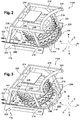
- the cutting disc 118 and the pickup system 120 are movable relative to each other in translation along the rear axis / forward Ar / Av, between a first configuration, illustrated on the figure 2 wherein the cutting disk 118 is advanced in the forward direction Av relative to the pickup system 120 by no more than five centimeters, preferably not more than two centimeters, and a second configuration, illustrated in FIG. figure 3 , wherein the cutting disc 118 is advanced in the forward direction Av with respect to the pickup system 120 by a clearance distance D of at least ten centimeters, preferably at least twenty centimeters.
- the cutting disk 118 is advanced, in the second configuration, a clearance distance D of thirty centimeters or more.
- the concentration fingers 240 protrude forwardly relative to the cutting disc 118 by at least three centimeters, for example five centimeters or more.
- the cutting disc 118 protrudes forwardly from the concentration fingers 240 by at least fifteen centimeters, preferably twenty-five centimeters or more.
- the cutting disc 118 in the second configuration is disengaged on its top and bottom along more than half, preferably more than three quarters, of the clearance distance D, i.e. no part of the cutting machine 110 is above or below the cutting disc 118 along the front half, preferably three quarters front, of the clearance distance D.
- the cutting disc 118 is advanced relative to the collection system 120 as explained above, but also with respect to the fingers of concentration 240.
- the cutting and pickup member 110A further includes a pattern modification system adapted to move the cutting disc and the pickup discs relative to each other between the first and second configurations.
- this configuration modification system comprises hydraulic cylinders 242 designed to move the movable plate 226 with respect to the frame 116.
- the cutting disc 118 is carried by the frame 116. More precisely, with reference to the figure 4 , the frame further comprises a fixed plate 402 extending between the two lower longitudinal members 204, 206 and fixed thereto.
- the fixed plateau 402 is located below the movable plate 226 and carries the cutting disc 118, so that the latter is rotatable relative to the fixed plate 402 about an axis of rotation, but connected to the fixed plate with respect to at least the translational movement the along the rear axis / front Ar / Av.
- the cutting disc 118 is connected to the fixed plate 402 for all movements other than the rotation about its axis of rotation.
- the collection system 120 comprises a cylinder 502 for supporting four pickup discs 504, 506, 508, 510.
- the pickup discs 504, 506, 508, 510 rotate at the same speed about the same axis.
- the pickup discs 504, 506, 508, 510 have different dentitions with respect to each other, in order to jam the plants in several dentitions at a time.
- the teeth In order not to cut the conveyed plants, the teeth have teeth having a thickness greater than five millimeters, preferably greater than one centimeter.
- the cutting and pickup element 110A includes a drive system of the cutting disc 118 and the pickup system 120, located under the hood and adapted to drive the cutting disc 118 and the pickup system at respective speeds. different.
- the drive system is particularly adapted to drive the cutting disc 118 into either the first configuration or the second configuration.
- the drive system firstly includes a drive motor for the cutting disc 118, called the cutting motor 602, and a torque transmitter 604 connecting the cutting motor 602 to the cutting disc 118, through a slot 606 formed in the movable platen 226.
- the cutting motor 602 is adapted to drive the cutting disc 118 to speeds greater than 200 rpm, preferably greater than 800 rpm, or even 1200 rpm. minute.
- the purpose of the torque transmitter 604 is to protect the cutting motor 602 by uncoupling the cutting motor 602 from the cutting disc 118 in case of blockage of the latter.
- the drive system further includes a pickup system drive motor 120, referred to as the pickup motor 608, which is different from the pickup motor 602.
- the pickup motor 606 is adapted to drive the support roll 502 to speeds between fifteen and forty revolutions per minute, but preferably not beyond.
- the drive system of the cutting disc 118 and the pickup system 120 further includes a gear connecting the pickup motor 608 to the pickup support cylinder 502.
- This gear comprises a large gear 610, whose teeth are directed inwards.
- the large toothed wheel 610 is carried by the movable plate 226 and is rotatable relative thereto.
- the support roll 502 of the pickup discs is attached to the large gear 610.
- the gear further comprises a small gear 612 coupled to the pickup motor 606, which is engaged with the large gear 610 and eccentric relative to the gear wheel 610. to this last.
- the other cutting and pickup element 110B is identical to that described above, except that its pickup discs rotate in an opposite direction to convey the cut plants to the common outlet 122.
- a user of the work machine 100 activates the controller 130 to configure the cutter and pickup elements 110A, 110B in their first configuration.
- a step 804 in response to user actuation, the controller 130 operates the pattern modification system of each element 110A, 110B to move the cutting disc 118 and the pickup system 120 relative to each other until the first configuration.
- the control device 130 actuates, on the one hand, the cutting motor 602 for rotating the cutting disc 118 at a first cutting speed, preferably greater than 800 revolutions per second. minute, and, secondly, the pickup motor 612 for rotating the pickup discs 228, 230, 232, 234 at a pickup speed preferably between fifteen and forty revolutions per minute.
- a step 808 the user advances the moving vehicle 102, so that the cutting machine 110 is moved in the direction before Av.
- the cutting and gathering machine 110 encounters the plants 112 of the undergrowth, cuts them and picks them up, according to the following steps 812 and 814 implemented by each cutting and pickup element 110A. , 110B.
- the concentration fingers 240 concentrate the plants 112 together, while the cutting disc 118 mows them.
- the pickup system 120 conveys the cut plants.
- the pickup discs 504, 506, 508, 510 wedge the cut plants between their teeth and drive them in their rotation.
- the scrubber 236 separates the plants from the pickup discs 504, 506, 508, 510 to reach the outlet 122.
- the sweeping means 122 of the press machine 124 bring the cut plants into the latter.
- the press machine 124 agglomerates and twines the cut plants.
- the press machine 124 provides a bale 128.
- the user detects a tree of large diameter that does not make it possible to collect it by the collection system 120 (for example a tree whose diameter is greater than the distance between the concentration fingers 240) on the road of the work machine 100 and actuates the control device 130 to configure the cutting and pickup elements 110A, 110B in their second configuration.
- a tree of large diameter that does not make it possible to collect it by the collection system 120 (for example a tree whose diameter is greater than the distance between the concentration fingers 240) on the road of the work machine 100 and actuates the control device 130 to configure the cutting and pickup elements 110A, 110B in their second configuration.
- a step 824 in response to user actuation, the controller 130 operates the pattern modification system of each element 110A, 110B to move the cutting disc 118 and the pickup system 120 one with respect to the other until the second configuration.
- control device 130 actuates, on the one hand, the cutting motor 602 for rotating the cutting disc 118 at a second cutting speed, preferably greater than the first cutting speed, and, on the other hand, the pickup motor 612 to stop it.
- a step 828 the user advances the moving vehicle 102, so that the cutting machine 110 is moved in the direction before Av.
- a step 830 the cutting disc 118 reaches and cuts the shaft.
- a step 832 once the tree is cut, the user uses the crane 104 to grip the trunk of the shaft in its clamp 108 and, for example, move it to the cutting disc 118 so as to cut the trunk into small sections.
- the process can then return to step 802.
- FIGS. 9 and 10 illustrate a cutting and gathering machine 900 according to a second embodiment of the invention that can be used in the machine 100 in place of the cutting and pickup machine 110.
- the cutting and picking machine 900 has two identical side-by-side 900A, 900B pickup and pickup elements. Thus, only the cutting and collecting element 900A will be described in detail later.
- the cutting and collecting element 900A comprises, as before, a frame 116 provided with a fixed plate 402, a disk cutter 118 carried by the fixed plate 402 and a pickup system 120 comprising a carrier cylinder 502 of pickup discs 228.
- the frame 116 this time has a rising rim 902 located opposite the other cutting and pickup element 900B and extending from the fixed plate 402 upwards.
- the cutter and pickup member 900A further includes a movable platen 904 and a pivot link 906 along the low / high axis the binder to the upstanding flange 902.
- the support roll 502 of the pickup discs 228 is carried by the moving plate 904. More specifically, in the example shown, the support roll 502 extends above the movable plate 904, between the latter and the fixed plate 402.
- a carousel 910 for driving the support cylinder 502 of the pickup discs 228.
- the carousel 910 has a central base 912 attached to a roof 914 of the support roll 502, and arms 916 extending obliquely to the bottom from the central base 912 to link the latter to the movable plate 904, via a circular groove 918 rising from the movable plate 904.
- Rollers 920 are also provided around the circular groove 918 to guide the support cylinder 502.
- the pickup motor is in the central base 1104.
- the movable plate 904, and therefore the pickup system 120 is thus rotatable relative to the frame 116 around the pivot connection 906 between a first configuration, identical to that of the figure 2 and a second configuration, indicated with apostrophed references, in which not only the cutting disc 118 is advanced in the forward direction Av relative to the pickup system 120 of the clearance distance D, but also the pickup system 120 is further apart, along the right / left axis, the other cutter and pickup element 900B than in the first position, a lateral spacing value EL of at least ten centimeters.
- the cutting and gathering machine 900 comprises a configuration modification system for simultaneously passing the pickup system 120 of the two cutting and pickup elements 900A, 900B from their first position to their second position, and vice versa.
- the configuration modification system comprises a cylinder 908 linking the two moving plates 904 and spacing them from one another by lying down.
- the lateral spacing of the collection systems 120 from each other in the second configuration of the elements 900A, 900B, makes it possible to clear the access to the outlet 122 of the cutting and collecting machine 900, for example to to pass tree trunks that the pickup system 120 could not convey because of their size.
- the process of cutting and collecting the figure 8 also applies to the machine 900, except that it may further include, after step 832, a step during which the user passes, using the crane 104, the sections of tree trunk between the collection systems 120 to the outlet 122. Thus, even the tree trunks can be integrated into the balls 128.
- the movable plate could be movable in translation at an angle in order to disengage the cutting disk and to separate the collection systems from one another, as is the case on the figure 9 .
- cutting disc also cover the case of several cutting discs, for example superimposed on one another.
- a cutting disk comprises one or more rotatable parts for cutting plants.
- the pickup system could be fixed relative to the frame, while the cutting disc would be movable relative to the same frame.
- the invention could use a cutting member, whether it is a circular cutter (for example with a cutting disk as described above, or else with a cutting chain) or not (for example, scissors or mobile combs stacked).
Landscapes
- Life Sciences & Earth Sciences (AREA)
- Biodiversity & Conservation Biology (AREA)
- Ecology (AREA)
- Forests & Forestry (AREA)
- Environmental Sciences (AREA)
- Harvester Elements (AREA)
Claims (10)
- Element zum Schneiden und Aufsammeln von Pflanzen, aufweisend:- ein Schneideorgan (118), das konstruiert ist, um die Pflanzen zu schneiden, wenn das Element zum Schneiden und Aufsammeln von einer Hinter/Vorderachse (Ar/Av) in eine Vorwärtsrichtung (Av) verlagert wird,- ein Sammelsystem (120), das konstruiert ist, um die geschnittenen Pflanzen zu einem Ausgang (122) des Elements zum Schneiden und Aufsammeln zu befördern, und- ein Antriebssystem (602, 608) des Schneideorgans (118) und des Sammelsystems (120),dadurch gekennzeichnet, dass das Schneideorgan (118) und das Sammelsystem (120) zwischen einer ersten Konfiguration, wobei das Schneideorgan (118) in Bezug zum Sammelsystem (120) höchsten fünf Zentimeter in die Vorwärtsrichtung (Av) vorwärtsbewegt wird, und einer zweiten Konfiguration, wobei das Schneideorgan (118) in Bezug zum Sammelsystem (120) mindestens zehn Zentimeter in die Vorwärtsrichtung (Av) in einen Freigabeabstand (D) vorwärtsbewegt wird, zueinander beweglich sind, und dass das Antriebssystem (602, 608) konstruiert ist, um das Schneideorgan (118) in die erste und die zweite Konfiguration anzutreiben.
- Element zum Schneiden und Aufsammeln nach Anspruch 1, umfassend ein Gestell (116), welches das Schneideorgan (118) trägt und wobei das Sammelsystem (120) von einem in Bezug zum Gestell (116) beweglichen Teil (226; 904) getragen wird.
- Element zum Schneiden und Aufsammeln nach Anspruch 1 oder 2, wobei das Schneideorgan (118) und das Sammelsystem (120) entlang der Vorder/Hinterachse (Ar/Av) in Bezug zueinander verschiebend beweglich sind.
- Element zum Schneiden und Aufsammeln nach Anspruch 1 oder 2, wobei das Schneideorgan (118) und das Sammelsystem (120) um eine Achse, die senkrecht zur Vorwärtsrichtung ist, in Bezug zueinander rotierend beweglich sind.
- Element zum Schneiden und Aufsammeln nach einem der Ansprüche 1 bis 4, umfassend ein Konfigurationsänderungssystem, das konstruiert ist, um das Schneideorgan (118) und das Sammelsystem (120) in Bezug zueinander zwischen der ersten und der zweiten Konfiguration zu verlagern.
- Element zum Schneiden und Aufsammeln nach einem der Ansprüche 1 bis 5, wobei das Sammelsystem (120) eine oder mehrere Sammelscheiben (228) aufweist, jede mit einer Peripherie ausgestattet, die Sammelzähne aufweist, die konstruiert sind, um die geschnittenen Pflanzen, die sich zwischen den Sammelzähnen erstrecken, zu befördern.
- Element zum Schneiden und Aufsammeln de Pflanzen nach einem der Ansprüche 1 bis 6, wobei das Antriebssystem des Schneideorgans und des Sammelsystems aufweist:- einen Antriebsmotor (602) des Schneideorgans (118),- einen Antriebsmotor (608) des Sammelsystems (120), der sich vom Antriebsmotor (602) des Schneideorgans (118) unterscheidet.
- Maschine zum Schneiden und Aufsammeln von Pflanzen, dadurch gekennzeichnet, dass sie zwei Elemente zum Schneiden und Aufsammeln von Pflanzen aufweist, jedes nach einem der Ansprüche 1 bis 7, wobei sich die zwei Elemente zum Schneiden und Aufsammeln denselben Ausgang (122) geschnittener Pflanzen teilen, wobei sich dieser Ausgang (122) zwischen ihnen befindet.
- Arbeitsgerät, dadurch gekennzeichnet, dass es aufweist:- ein bewegliches Fahrzeug,- ein Element zum Schneiden und Aufsammeln nach einem der Ansprüche 1 bis 7, das an dem beweglichen Fahrzeug befestigt ist, oder eine Maschine zum Schneiden und Aufsammeln nach Anspruch 8, die an dem beweglichen Fahrzeug befestigt ist.
- Verfahren zum Schneiden und Aufsammeln von Pflanzen, dadurch gekennzeichnet, dass es die folgenden Schritte aufweist:- Verlagern eines Schneideorgans (118) eines Elements zum Schneiden und Aufsammeln und eines Sammelsystems (120) dieses selben Elements in Bezug zueinander, bis in die erste Konfiguration, wobei das Schneideorgan (118) in Bezug zum Sammelsystem (120) höchsten fünf Zentimeter in die Vorwärtsrichtung (Av) vorwärtsbewegt wird, wobei das Schneideorgan (118) konstruiert ist, um die Pflanzen zu schneiden, wenn das Element zum Schneiden und Aufsammeln in die Vorwärtsrichtung (Av) bewegt wird, und das Sammelsystem (120) konstruiert ist, um die geschnittenen Pflanzen zu einem Ausgang (122) des Elements zum Schneiden und Aufsammeln zu befördern,- Schneiden der Pflanzen mit Hilfe des Schneideorgans (118) und Aufsammeln der geschnittenen Pflanzen mit Hilfe des Sammelsystems (120),- Verlagern des Schneideorgans (118) und des Sammelsystem (120) in Bezug zueinander bis in eine zweite Konfiguration, wobei das Schneideorgan (118) in Bezug zum Sammelsystem (120) mindestens zehn Zentimeter in die Vorwärtsrichtung (Av) in einen Freigabeabstand (D) vorwärtsbewegt wird, und- Schneiden der Pflanzen mit Hilfe des Schneideorgans (118).
Applications Claiming Priority (1)
| Application Number | Priority Date | Filing Date | Title |
|---|---|---|---|
| FR1057657A FR2965146B1 (fr) | 2010-09-23 | 2010-09-23 | Element et machine de coupe et de ramassage de plantes, engin de travail comportant un tel element ou une telle machine et procede de coupe et de ramassage de plantes |
Publications (2)
| Publication Number | Publication Date |
|---|---|
| EP2433487A1 EP2433487A1 (de) | 2012-03-28 |
| EP2433487B1 true EP2433487B1 (de) | 2016-05-11 |
Family
ID=44225726
Family Applications (1)
| Application Number | Title | Priority Date | Filing Date |
|---|---|---|---|
| EP11181431.5A Not-in-force EP2433487B1 (de) | 2010-09-23 | 2011-09-15 | Element und Maschine zum Schneiden und Aufsammeln von Pflanzen, Arbeitsgerät, das ein solches Element oder eine solche Maschine enthält, und Verfahren zum Schneiden und Aufsammeln von Pflanzen |
Country Status (4)
| Country | Link |
|---|---|
| EP (1) | EP2433487B1 (de) |
| ES (1) | ES2601031T3 (de) |
| FR (1) | FR2965146B1 (de) |
| PT (1) | PT2433487T (de) |
Families Citing this family (4)
| Publication number | Priority date | Publication date | Assignee | Title |
|---|---|---|---|---|
| CN105594467A (zh) * | 2016-03-03 | 2016-05-25 | 四川省农业机械研究设计院 | 立式茶园三面修剪机 |
| CN107466691B (zh) * | 2017-09-28 | 2022-08-23 | 桂林电子科技大学 | 一种可变距绿化带修剪浇灌装置及其使用方法 |
| CN114847120B (zh) * | 2022-05-23 | 2024-06-21 | 燕山大学 | 具有砍伐、去枝和定长劈木功能的伐木机 |
| CN115669393A (zh) * | 2022-11-15 | 2023-02-03 | 中山亘新机械设备有限公司 | 绿篱修剪机及工程作业车 |
Family Cites Families (6)
| Publication number | Priority date | Publication date | Assignee | Title |
|---|---|---|---|---|
| FR2553969A1 (fr) * | 1983-10-26 | 1985-05-03 | Landeghem Van | Dispositif pour l'abattage des arbres |
| DE4238007A1 (de) | 1992-03-27 | 1994-05-19 | Wieneke Franz | Mähhacker für Gehölze |
| DE4416195A1 (de) * | 1993-05-18 | 1994-11-24 | Josef Gres | Verfahren und Vorrichtung zum Fällen und Verarbeiten von Bäumen |
| DE9316683U1 (de) * | 1993-11-02 | 1994-02-10 | Claas OHG beschränkt haftende offene Handelsgesellschaft, 33428 Harsewinkel | Feldhäcksler |
| FR2723507A1 (fr) * | 1994-08-11 | 1996-02-16 | Binger France Sarl | Machine de coupe utilisable notamment pour la taille ou pretaille de vignes palissees |
| DE102007050042B4 (de) * | 2007-10-17 | 2009-07-09 | Stoll Gmbh Maschinenbau | Häcksler und Aufnahmevorrichtung für Schnittgut |
-
2010
- 2010-09-23 FR FR1057657A patent/FR2965146B1/fr not_active Expired - Fee Related
-
2011
- 2011-09-15 PT PT111814315T patent/PT2433487T/pt unknown
- 2011-09-15 EP EP11181431.5A patent/EP2433487B1/de not_active Not-in-force
- 2011-09-15 ES ES11181431.5T patent/ES2601031T3/es active Active
Also Published As
| Publication number | Publication date |
|---|---|
| PT2433487T (pt) | 2016-08-18 |
| ES2601031T3 (es) | 2017-02-14 |
| EP2433487A1 (de) | 2012-03-28 |
| FR2965146A1 (fr) | 2012-03-30 |
| FR2965146B1 (fr) | 2012-10-05 |
Similar Documents
| Publication | Publication Date | Title |
|---|---|---|
| EP0312126B1 (de) | Schneidapparat zur Verwendung in der Landwirtschaft, dem Weinbau und der Baumgärtnerei | |
| EP2433488B1 (de) | Vorrichtung zum automatischen Herumführen von Pfählen für Obstspaliere, und diese verwendende landwirtschaftliche Maschinen | |
| EP0408090B1 (de) | Kreiselmäher | |
| EP2731414B1 (de) | Gelenkige Aufnehmervorrichtung und landwirtschaftliche Maschine mit einer solchen Vorrichtung | |
| EP1690446B1 (de) | Landwirtschaftliches Gerät für das Mähen von Produkten | |
| CA2474392C (fr) | Machine agricole pour grouper des produits se trouvant sur le sol | |
| EP2433487B1 (de) | Element und Maschine zum Schneiden und Aufsammeln von Pflanzen, Arbeitsgerät, das ein solches Element oder eine solche Maschine enthält, und Verfahren zum Schneiden und Aufsammeln von Pflanzen | |
| FR2572881A1 (fr) | Faucheuse comportant un chassis muni d'une structure intermediaire et de moyens destines a empecher l'accrochage de fourrage a la dite structure intermediaire. | |
| EP0366580A1 (de) | Mähmaschine mit Schneidelementen | |
| EP0175629A1 (de) | Kreiselmäher | |
| EP2720528B1 (de) | Maschine zum automatischen ziehen von abgeschnittenen weinreben | |
| EP0337909A1 (de) | Direktangetriebene Mähmaschine | |
| EP1168908A1 (de) | Verbesserung eines selbstgesteuerten rasenmähers | |
| CA2380681C (fr) | Machine de fenaison | |
| EP0772969B1 (de) | Heuwerbungsmaschine mit mindestens einem Rotor zum Schwaden | |
| EP2896289B1 (de) | Durchbrochene Drehtrommel mit Anziehungskraft zum Entlauben von Pflanzen, und Entlaubungsköpfe, die mit einer solchen Trommel ausgestattet sind | |
| EP0089257B1 (de) | Schwadenmäher und Verfahren zur Schwadgruppierung | |
| EP1434476B1 (de) | Landmaschine, insbesondere kreiselmäher, mit verbesserter schneidvorrichtung | |
| FR2628933A1 (fr) | Dispositif pour recolter des ombelles, notamment d'oignons ou de poireaux | |
| EP3935934A1 (de) | Landwirtschaftliches gerät mit einem mähbalken und einem abnehmbaren kollektor und landwirtschaftliche maschine mit einem solchen gerät | |
| EP1790211B1 (de) | Vorschneidemaschine mit integrierten Ausweichmitteln für Pfähle oder ähnliches | |
| EP0016712B1 (de) | Maschine zum Entblättern und Köpfen von Rüben oder ähnlicher Pflanzen | |
| EP0095613A2 (de) | Maschine zum Zerschneiden und Wiedergewinnen der Rückstände beim Fällen von Bäumen | |
| FR2778526A1 (fr) | Machine pour recolter et botteler des produits agricoles | |
| EP1391148B1 (de) | Mähmaschine für halmähnliche Gewächse |
Legal Events
| Date | Code | Title | Description |
|---|---|---|---|
| PUAI | Public reference made under article 153(3) epc to a published international application that has entered the european phase |
Free format text: ORIGINAL CODE: 0009012 |
|
| AK | Designated contracting states |
Kind code of ref document: A1 Designated state(s): AL AT BE BG CH CY CZ DE DK EE ES FI FR GB GR HR HU IE IS IT LI LT LU LV MC MK MT NL NO PL PT RO RS SE SI SK SM TR |
|
| AX | Request for extension of the european patent |
Extension state: BA ME |
|
| 17P | Request for examination filed |
Effective date: 20120726 |
|
| GRAP | Despatch of communication of intention to grant a patent |
Free format text: ORIGINAL CODE: EPIDOSNIGR1 |
|
| RIC1 | Information provided on ipc code assigned before grant |
Ipc: A01G 3/04 20060101AFI20151104BHEP Ipc: A01G 23/093 20060101ALI20151104BHEP |
|
| INTG | Intention to grant announced |
Effective date: 20151201 |
|
| GRAS | Grant fee paid |
Free format text: ORIGINAL CODE: EPIDOSNIGR3 |
|
| GRAA | (expected) grant |
Free format text: ORIGINAL CODE: 0009210 |
|
| AK | Designated contracting states |
Kind code of ref document: B1 Designated state(s): AL AT BE BG CH CY CZ DE DK EE ES FI FR GB GR HR HU IE IS IT LI LT LU LV MC MK MT NL NO PL PT RO RS SE SI SK SM TR |
|
| REG | Reference to a national code |
Ref country code: GB Ref legal event code: FG4D Free format text: NOT ENGLISH |
|
| REG | Reference to a national code |
Ref country code: CH Ref legal event code: EP |
|
| REG | Reference to a national code |
Ref country code: AT Ref legal event code: REF Ref document number: 797881 Country of ref document: AT Kind code of ref document: T Effective date: 20160515 |
|
| REG | Reference to a national code |
Ref country code: IE Ref legal event code: FG4D Free format text: LANGUAGE OF EP DOCUMENT: FRENCH |
|
| REG | Reference to a national code |
Ref country code: DE Ref legal event code: R096 Ref document number: 602011026358 Country of ref document: DE |
|
| REG | Reference to a national code |
Ref country code: PT Ref legal event code: SC4A Ref document number: 2433487 Country of ref document: PT Date of ref document: 20160818 Kind code of ref document: T Free format text: AVAILABILITY OF NATIONAL TRANSLATION Effective date: 20160811 |
|
| REG | Reference to a national code |
Ref country code: LT Ref legal event code: MG4D |
|
| REG | Reference to a national code |
Ref country code: NL Ref legal event code: MP Effective date: 20160511 |
|
| REG | Reference to a national code |
Ref country code: FR Ref legal event code: PLFP Year of fee payment: 6 |
|
| PG25 | Lapsed in a contracting state [announced via postgrant information from national office to epo] |
Ref country code: LT Free format text: LAPSE BECAUSE OF FAILURE TO SUBMIT A TRANSLATION OF THE DESCRIPTION OR TO PAY THE FEE WITHIN THE PRESCRIBED TIME-LIMIT Effective date: 20160511 Ref country code: FI Free format text: LAPSE BECAUSE OF FAILURE TO SUBMIT A TRANSLATION OF THE DESCRIPTION OR TO PAY THE FEE WITHIN THE PRESCRIBED TIME-LIMIT Effective date: 20160511 Ref country code: NO Free format text: LAPSE BECAUSE OF FAILURE TO SUBMIT A TRANSLATION OF THE DESCRIPTION OR TO PAY THE FEE WITHIN THE PRESCRIBED TIME-LIMIT Effective date: 20160811 Ref country code: NL Free format text: LAPSE BECAUSE OF FAILURE TO SUBMIT A TRANSLATION OF THE DESCRIPTION OR TO PAY THE FEE WITHIN THE PRESCRIBED TIME-LIMIT Effective date: 20160511 |
|
| REG | Reference to a national code |
Ref country code: AT Ref legal event code: MK05 Ref document number: 797881 Country of ref document: AT Kind code of ref document: T Effective date: 20160511 |
|
| PG25 | Lapsed in a contracting state [announced via postgrant information from national office to epo] |
Ref country code: HR Free format text: LAPSE BECAUSE OF FAILURE TO SUBMIT A TRANSLATION OF THE DESCRIPTION OR TO PAY THE FEE WITHIN THE PRESCRIBED TIME-LIMIT Effective date: 20160511 Ref country code: SE Free format text: LAPSE BECAUSE OF FAILURE TO SUBMIT A TRANSLATION OF THE DESCRIPTION OR TO PAY THE FEE WITHIN THE PRESCRIBED TIME-LIMIT Effective date: 20160511 Ref country code: RS Free format text: LAPSE BECAUSE OF FAILURE TO SUBMIT A TRANSLATION OF THE DESCRIPTION OR TO PAY THE FEE WITHIN THE PRESCRIBED TIME-LIMIT Effective date: 20160511 Ref country code: LV Free format text: LAPSE BECAUSE OF FAILURE TO SUBMIT A TRANSLATION OF THE DESCRIPTION OR TO PAY THE FEE WITHIN THE PRESCRIBED TIME-LIMIT Effective date: 20160511 Ref country code: GR Free format text: LAPSE BECAUSE OF FAILURE TO SUBMIT A TRANSLATION OF THE DESCRIPTION OR TO PAY THE FEE WITHIN THE PRESCRIBED TIME-LIMIT Effective date: 20160812 |
|
| PG25 | Lapsed in a contracting state [announced via postgrant information from national office to epo] |
Ref country code: SK Free format text: LAPSE BECAUSE OF FAILURE TO SUBMIT A TRANSLATION OF THE DESCRIPTION OR TO PAY THE FEE WITHIN THE PRESCRIBED TIME-LIMIT Effective date: 20160511 Ref country code: RO Free format text: LAPSE BECAUSE OF FAILURE TO SUBMIT A TRANSLATION OF THE DESCRIPTION OR TO PAY THE FEE WITHIN THE PRESCRIBED TIME-LIMIT Effective date: 20160511 Ref country code: EE Free format text: LAPSE BECAUSE OF FAILURE TO SUBMIT A TRANSLATION OF THE DESCRIPTION OR TO PAY THE FEE WITHIN THE PRESCRIBED TIME-LIMIT Effective date: 20160511 Ref country code: CZ Free format text: LAPSE BECAUSE OF FAILURE TO SUBMIT A TRANSLATION OF THE DESCRIPTION OR TO PAY THE FEE WITHIN THE PRESCRIBED TIME-LIMIT Effective date: 20160511 Ref country code: DK Free format text: LAPSE BECAUSE OF FAILURE TO SUBMIT A TRANSLATION OF THE DESCRIPTION OR TO PAY THE FEE WITHIN THE PRESCRIBED TIME-LIMIT Effective date: 20160511 |
|
| REG | Reference to a national code |
Ref country code: DE Ref legal event code: R097 Ref document number: 602011026358 Country of ref document: DE Ref country code: ES Ref legal event code: FG2A Ref document number: 2601031 Country of ref document: ES Kind code of ref document: T3 Effective date: 20170214 |
|
| PG25 | Lapsed in a contracting state [announced via postgrant information from national office to epo] |
Ref country code: PL Free format text: LAPSE BECAUSE OF FAILURE TO SUBMIT A TRANSLATION OF THE DESCRIPTION OR TO PAY THE FEE WITHIN THE PRESCRIBED TIME-LIMIT Effective date: 20160511 Ref country code: BE Free format text: LAPSE BECAUSE OF NON-PAYMENT OF DUE FEES Effective date: 20160930 Ref country code: AT Free format text: LAPSE BECAUSE OF FAILURE TO SUBMIT A TRANSLATION OF THE DESCRIPTION OR TO PAY THE FEE WITHIN THE PRESCRIBED TIME-LIMIT Effective date: 20160511 Ref country code: SM Free format text: LAPSE BECAUSE OF FAILURE TO SUBMIT A TRANSLATION OF THE DESCRIPTION OR TO PAY THE FEE WITHIN THE PRESCRIBED TIME-LIMIT Effective date: 20160511 |
|
| PLBE | No opposition filed within time limit |
Free format text: ORIGINAL CODE: 0009261 |
|
| STAA | Information on the status of an ep patent application or granted ep patent |
Free format text: STATUS: NO OPPOSITION FILED WITHIN TIME LIMIT |
|
| 26N | No opposition filed |
Effective date: 20170214 |
|
| PG25 | Lapsed in a contracting state [announced via postgrant information from national office to epo] |
Ref country code: MC Free format text: LAPSE BECAUSE OF FAILURE TO SUBMIT A TRANSLATION OF THE DESCRIPTION OR TO PAY THE FEE WITHIN THE PRESCRIBED TIME-LIMIT Effective date: 20160511 |
|
| REG | Reference to a national code |
Ref country code: CH Ref legal event code: PL |
|
| PG25 | Lapsed in a contracting state [announced via postgrant information from national office to epo] |
Ref country code: SI Free format text: LAPSE BECAUSE OF FAILURE TO SUBMIT A TRANSLATION OF THE DESCRIPTION OR TO PAY THE FEE WITHIN THE PRESCRIBED TIME-LIMIT Effective date: 20160511 |
|
| REG | Reference to a national code |
Ref country code: IE Ref legal event code: MM4A |
|
| PG25 | Lapsed in a contracting state [announced via postgrant information from national office to epo] |
Ref country code: CH Free format text: LAPSE BECAUSE OF NON-PAYMENT OF DUE FEES Effective date: 20160930 Ref country code: LI Free format text: LAPSE BECAUSE OF NON-PAYMENT OF DUE FEES Effective date: 20160930 Ref country code: IE Free format text: LAPSE BECAUSE OF NON-PAYMENT OF DUE FEES Effective date: 20160915 |
|
| PG25 | Lapsed in a contracting state [announced via postgrant information from national office to epo] |
Ref country code: LU Free format text: LAPSE BECAUSE OF NON-PAYMENT OF DUE FEES Effective date: 20160915 |
|
| REG | Reference to a national code |
Ref country code: FR Ref legal event code: PLFP Year of fee payment: 7 |
|
| REG | Reference to a national code |
Ref country code: BE Ref legal event code: MM Effective date: 20160930 |
|
| PG25 | Lapsed in a contracting state [announced via postgrant information from national office to epo] |
Ref country code: HU Free format text: LAPSE BECAUSE OF FAILURE TO SUBMIT A TRANSLATION OF THE DESCRIPTION OR TO PAY THE FEE WITHIN THE PRESCRIBED TIME-LIMIT; INVALID AB INITIO Effective date: 20110915 Ref country code: CY Free format text: LAPSE BECAUSE OF FAILURE TO SUBMIT A TRANSLATION OF THE DESCRIPTION OR TO PAY THE FEE WITHIN THE PRESCRIBED TIME-LIMIT Effective date: 20160511 |
|
| PG25 | Lapsed in a contracting state [announced via postgrant information from national office to epo] |
Ref country code: MT Free format text: LAPSE BECAUSE OF FAILURE TO SUBMIT A TRANSLATION OF THE DESCRIPTION OR TO PAY THE FEE WITHIN THE PRESCRIBED TIME-LIMIT Effective date: 20160511 Ref country code: MK Free format text: LAPSE BECAUSE OF FAILURE TO SUBMIT A TRANSLATION OF THE DESCRIPTION OR TO PAY THE FEE WITHIN THE PRESCRIBED TIME-LIMIT Effective date: 20160511 Ref country code: IS Free format text: LAPSE BECAUSE OF FAILURE TO SUBMIT A TRANSLATION OF THE DESCRIPTION OR TO PAY THE FEE WITHIN THE PRESCRIBED TIME-LIMIT Effective date: 20160511 Ref country code: TR Free format text: LAPSE BECAUSE OF FAILURE TO SUBMIT A TRANSLATION OF THE DESCRIPTION OR TO PAY THE FEE WITHIN THE PRESCRIBED TIME-LIMIT Effective date: 20160511 |
|
| PG25 | Lapsed in a contracting state [announced via postgrant information from national office to epo] |
Ref country code: BG Free format text: LAPSE BECAUSE OF FAILURE TO SUBMIT A TRANSLATION OF THE DESCRIPTION OR TO PAY THE FEE WITHIN THE PRESCRIBED TIME-LIMIT Effective date: 20160511 |
|
| REG | Reference to a national code |
Ref country code: FR Ref legal event code: PLFP Year of fee payment: 8 |
|
| PG25 | Lapsed in a contracting state [announced via postgrant information from national office to epo] |
Ref country code: AL Free format text: LAPSE BECAUSE OF FAILURE TO SUBMIT A TRANSLATION OF THE DESCRIPTION OR TO PAY THE FEE WITHIN THE PRESCRIBED TIME-LIMIT Effective date: 20160511 |
|
| PGFP | Annual fee paid to national office [announced via postgrant information from national office to epo] |
Ref country code: FR Payment date: 20190927 Year of fee payment: 9 Ref country code: IT Payment date: 20190925 Year of fee payment: 9 |
|
| PGFP | Annual fee paid to national office [announced via postgrant information from national office to epo] |
Ref country code: GB Payment date: 20190920 Year of fee payment: 9 |
|
| PGFP | Annual fee paid to national office [announced via postgrant information from national office to epo] |
Ref country code: ES Payment date: 20191022 Year of fee payment: 9 |
|
| PGFP | Annual fee paid to national office [announced via postgrant information from national office to epo] |
Ref country code: DE Payment date: 20200925 Year of fee payment: 10 |
|
| GBPC | Gb: european patent ceased through non-payment of renewal fee |
Effective date: 20200915 |
|
| PG25 | Lapsed in a contracting state [announced via postgrant information from national office to epo] |
Ref country code: FR Free format text: LAPSE BECAUSE OF NON-PAYMENT OF DUE FEES Effective date: 20200930 |
|
| PG25 | Lapsed in a contracting state [announced via postgrant information from national office to epo] |
Ref country code: GB Free format text: LAPSE BECAUSE OF NON-PAYMENT OF DUE FEES Effective date: 20200915 |
|
| PG25 | Lapsed in a contracting state [announced via postgrant information from national office to epo] |
Ref country code: IT Free format text: LAPSE BECAUSE OF NON-PAYMENT OF DUE FEES Effective date: 20200915 |
|
| REG | Reference to a national code |
Ref country code: ES Ref legal event code: FD2A Effective date: 20220118 |
|
| REG | Reference to a national code |
Ref country code: DE Ref legal event code: R119 Ref document number: 602011026358 Country of ref document: DE |
|
| PG25 | Lapsed in a contracting state [announced via postgrant information from national office to epo] |
Ref country code: ES Free format text: LAPSE BECAUSE OF NON-PAYMENT OF DUE FEES Effective date: 20200916 |
|
| PG25 | Lapsed in a contracting state [announced via postgrant information from national office to epo] |
Ref country code: DE Free format text: LAPSE BECAUSE OF NON-PAYMENT OF DUE FEES Effective date: 20220401 |
|
| PGFP | Annual fee paid to national office [announced via postgrant information from national office to epo] |
Ref country code: PT Payment date: 20220901 Year of fee payment: 12 |
|
| PG25 | Lapsed in a contracting state [announced via postgrant information from national office to epo] |
Ref country code: PT Free format text: LAPSE BECAUSE OF NON-PAYMENT OF DUE FEES Effective date: 20240315 |