EP2433540A2 - Nass-staubsammelvorrichtung für einen staubsauger - Google Patents
Nass-staubsammelvorrichtung für einen staubsauger Download PDFInfo
- Publication number
- EP2433540A2 EP2433540A2 EP10777870A EP10777870A EP2433540A2 EP 2433540 A2 EP2433540 A2 EP 2433540A2 EP 10777870 A EP10777870 A EP 10777870A EP 10777870 A EP10777870 A EP 10777870A EP 2433540 A2 EP2433540 A2 EP 2433540A2
- Authority
- EP
- European Patent Office
- Prior art keywords
- dust
- water
- water distribution
- bin
- distribution passage
- Prior art date
- Legal status (The legal status is an assumption and is not a legal conclusion. Google has not performed a legal analysis and makes no representation as to the accuracy of the status listed.)
- Granted
Links
Images

Classifications
-
- A—HUMAN NECESSITIES
- A47—FURNITURE; DOMESTIC ARTICLES OR APPLIANCES; COFFEE MILLS; SPICE MILLS; SUCTION CLEANERS IN GENERAL
- A47L—DOMESTIC WASHING OR CLEANING; SUCTION CLEANERS IN GENERAL
- A47L9/00—Details or accessories of suction cleaners, e.g. mechanical means for controlling the suction or for effecting pulsating action; Storing devices specially adapted to suction cleaners or parts thereof; Carrying-vehicles specially adapted for suction cleaners
- A47L9/10—Filters; Dust separators; Dust removal; Automatic exchange of filters
- A47L9/18—Liquid filters
- A47L9/182—Separating by passing the air over a liquid bath
-
- A—HUMAN NECESSITIES
- A47—FURNITURE; DOMESTIC ARTICLES OR APPLIANCES; COFFEE MILLS; SPICE MILLS; SUCTION CLEANERS IN GENERAL
- A47L—DOMESTIC WASHING OR CLEANING; SUCTION CLEANERS IN GENERAL
- A47L9/00—Details or accessories of suction cleaners, e.g. mechanical means for controlling the suction or for effecting pulsating action; Storing devices specially adapted to suction cleaners or parts thereof; Carrying-vehicles specially adapted for suction cleaners
- A47L9/10—Filters; Dust separators; Dust removal; Automatic exchange of filters
- A47L9/16—Arrangement or disposition of cyclones or other devices with centrifugal action
- A47L9/1608—Cyclonic chamber constructions
-
- A—HUMAN NECESSITIES
- A47—FURNITURE; DOMESTIC ARTICLES OR APPLIANCES; COFFEE MILLS; SPICE MILLS; SUCTION CLEANERS IN GENERAL
- A47L—DOMESTIC WASHING OR CLEANING; SUCTION CLEANERS IN GENERAL
- A47L9/00—Details or accessories of suction cleaners, e.g. mechanical means for controlling the suction or for effecting pulsating action; Storing devices specially adapted to suction cleaners or parts thereof; Carrying-vehicles specially adapted for suction cleaners
- A47L9/10—Filters; Dust separators; Dust removal; Automatic exchange of filters
- A47L9/16—Arrangement or disposition of cyclones or other devices with centrifugal action
- A47L9/1616—Multiple arrangement thereof
- A47L9/1625—Multiple arrangement thereof for series flow
-
- A—HUMAN NECESSITIES
- A47—FURNITURE; DOMESTIC ARTICLES OR APPLIANCES; COFFEE MILLS; SPICE MILLS; SUCTION CLEANERS IN GENERAL
- A47L—DOMESTIC WASHING OR CLEANING; SUCTION CLEANERS IN GENERAL
- A47L9/00—Details or accessories of suction cleaners, e.g. mechanical means for controlling the suction or for effecting pulsating action; Storing devices specially adapted to suction cleaners or parts thereof; Carrying-vehicles specially adapted for suction cleaners
- A47L9/10—Filters; Dust separators; Dust removal; Automatic exchange of filters
- A47L9/16—Arrangement or disposition of cyclones or other devices with centrifugal action
- A47L9/1616—Multiple arrangement thereof
- A47L9/1641—Multiple arrangement thereof for parallel flow
-
- A—HUMAN NECESSITIES
- A47—FURNITURE; DOMESTIC ARTICLES OR APPLIANCES; COFFEE MILLS; SPICE MILLS; SUCTION CLEANERS IN GENERAL
- A47L—DOMESTIC WASHING OR CLEANING; SUCTION CLEANERS IN GENERAL
- A47L9/00—Details or accessories of suction cleaners, e.g. mechanical means for controlling the suction or for effecting pulsating action; Storing devices specially adapted to suction cleaners or parts thereof; Carrying-vehicles specially adapted for suction cleaners
- A47L9/10—Filters; Dust separators; Dust removal; Automatic exchange of filters
- A47L9/16—Arrangement or disposition of cyclones or other devices with centrifugal action
- A47L9/165—Construction of inlets
-
- A—HUMAN NECESSITIES
- A47—FURNITURE; DOMESTIC ARTICLES OR APPLIANCES; COFFEE MILLS; SPICE MILLS; SUCTION CLEANERS IN GENERAL
- A47L—DOMESTIC WASHING OR CLEANING; SUCTION CLEANERS IN GENERAL
- A47L9/00—Details or accessories of suction cleaners, e.g. mechanical means for controlling the suction or for effecting pulsating action; Storing devices specially adapted to suction cleaners or parts thereof; Carrying-vehicles specially adapted for suction cleaners
- A47L9/10—Filters; Dust separators; Dust removal; Automatic exchange of filters
- A47L9/16—Arrangement or disposition of cyclones or other devices with centrifugal action
- A47L9/1658—Construction of outlets
- A47L9/1666—Construction of outlets with filtering means
-
- A—HUMAN NECESSITIES
- A47—FURNITURE; DOMESTIC ARTICLES OR APPLIANCES; COFFEE MILLS; SPICE MILLS; SUCTION CLEANERS IN GENERAL
- A47L—DOMESTIC WASHING OR CLEANING; SUCTION CLEANERS IN GENERAL
- A47L9/00—Details or accessories of suction cleaners, e.g. mechanical means for controlling the suction or for effecting pulsating action; Storing devices specially adapted to suction cleaners or parts thereof; Carrying-vehicles specially adapted for suction cleaners
- A47L9/10—Filters; Dust separators; Dust removal; Automatic exchange of filters
- A47L9/16—Arrangement or disposition of cyclones or other devices with centrifugal action
- A47L9/1683—Dust collecting chambers; Dust collecting receptacles
-
- A—HUMAN NECESSITIES
- A47—FURNITURE; DOMESTIC ARTICLES OR APPLIANCES; COFFEE MILLS; SPICE MILLS; SUCTION CLEANERS IN GENERAL
- A47L—DOMESTIC WASHING OR CLEANING; SUCTION CLEANERS IN GENERAL
- A47L9/00—Details or accessories of suction cleaners, e.g. mechanical means for controlling the suction or for effecting pulsating action; Storing devices specially adapted to suction cleaners or parts thereof; Carrying-vehicles specially adapted for suction cleaners
- A47L9/10—Filters; Dust separators; Dust removal; Automatic exchange of filters
- A47L9/18—Liquid filters
- A47L9/186—Construction of outlets
- A47L9/187—Construction of outlets with filtering means, e.g. separators
Definitions
- the present invention relates to a wet type dust collecting apparatus of a vacuum cleaner, which collects foreign substance, such as dust or dirt, by using water.
- US Patents Nos. 4,238,869 , 7,293,324 and 4,800,615 and KR patents Nos. 790781 and 779190 disclose a configuration on a vacuum cleaner with a single dust bin formed, so that a user can easily observe water filled therein.
- the above described prior art 1 presents an inconvenience in that if it is applied to a dust collecting apparatus with first and second dust bins, the user should separately fill the first and second dust bins with water in use.
- JP Patent Laid-Open No. 2003-205214 discloses a configuration on a dust bin in which first and second dust collecting areas thereof can be simultaneously filled with water. According to this, the prior art 2 improves an convenience in that the user can simultaneously fill the first and second dust collecting areas of the dust bin with water in use.
- the prior art 2 presents a problem in that the dust separating efficiency may be deteriorated due to a pressure difference between the first and second dust collecting areas.
- the prior art 2 may not maintain a proper water level in the respective dust collecting areas, because if the there is the pressure difference between the first and second dust collecting areas, the water is unceasingly moved from the first dust collecting area to the second dust collecting area or vice versa. Owing to this, the dust separating efficiency can not only be deteriorated, but also the water in the dust collecting area increased in water level may be flowed into the vacuum cleaner. The water flowed into the vacuum cleaner may cause filters, electronic parts, such as a fan motor and a circuit board, or the like of the vacuum cleaner to malfunction or to be damaged.
- An aspect of the present invention is to provide a wet type dust collecting apparatus of a vacuum cleaner having a plurality of dust collecting areas, which can prevent water filled in at least one of the plurality of dust collecting areas from moving to other dust collecting areas.
- Another aspect of the present invention is to provide a wet type dust collecting apparatus of a vacuum cleaner, which can uniformly maintain an exhaust pressure in a plurality of dust collecting areas thus to prevent an dust separating efficiency from being deteriorated.
- a wet type dust collecting apparatus of a vacuum cleaner includes a dust bin having at least two dust collecting areas, each of which at least one water inflow hole is formed, and a water distribution passage part to connect the water inflow holes in communication with each other; and a dust bin cover coupled to the dust bin and having a sealing member to open and close up at least one of the water inflow holes.
- the sealing member to open and close up the water inflow holes prevents water from moving through the water inflow holes formed in the dust collecting areas in operation of the vacuum cleaner.
- the water distribution passage part may include chambers formed on respective dust collecting areas to communicate with the respective water inflow holes; and at least one dust bin-water distribution passage to connect the chambers.
- the wet type dust collecting apparatus may further include a lower cover coupled to a bottom surface of the dust bin to form the water distribution passage part.
- the water distribution passage part may include a dust bin-water distribution passage part formed on the bottom surface of the dust bin; and a lower cover-water distribution passage part formed on an upper surface of the lower cover to couple with the dust bin-water distribution passage part and thus to form the water distribution passage part.
- the dust bin-water distribution passage part may include chamber ribs projected and formed to a lower part of the dust bin from outer circumferences of the water inflow holes and water distribution passage ribs projected and formed to connect the chamber ribs.
- the lower cover-water distribution passage part may include chamber rib groove to which the chamber ribs are coupled and water distribution passage rib grooves to which the water distribution passage ribs are coupled.
- the dust bin may include a first dust bin to form a first dust collecting area and a plurality of second dust bins to form a plurality of second dust collecting areas.
- the sealing member may be coupled with a first water inflow hole formed in the first bin thus to separate the area of the first bin and the areas of the second dust bins from each other.
- the dust bin may further include a quantity-of-water display part communicated with the water distribution passage and configured to observe a level of the water filled in the dust bin.
- a wet type duct collecting apparatus 1 includes a first dust bin 310 to form a first dust collecting area 310c, and a plurality of second dust bins 350 to form a plurality of dust collecting areas 350c (see FIG. 5 ).
- chambers are made up of a first chamber 310a and a second chamber 350a
- water distribution passages are made up of a quantity-of-water display part-water distribution passage 330 and a dust bin-water distribution passage 320
- water inflow holes are made up of a first water inflow hole 313 and a second water inflow hole 353 (see FIG. 5 ).
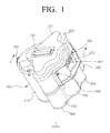
- FIG. 1 is a perspective view illustrating the wet type dust collecting apparatus 1 according to the exemplary embodiment of the present invention
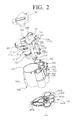
- FIG 2 is an exploded perspective view of the wet type dust collecting apparatus shown in FIG. 1 .
- the wet type dust collecting apparatus 1 includes a dust bin cover 200, a first exhaust pipe unit 210, a plurality of inflow pipe units 230, a dust bin 300, and a lower cover 400.
- the dust bin cover 200 includes a first inlet 201, a first outlet 202, second inlets 231 formed therein.
- the dust bin cover 200 includes a second passage cover to form a second passage 240.
- the first inlet 201 is formed on a side of the dust bin cover 200 to draw outer air drawn in from a brush assembly (not shown) or the like into the dust bin 300.
- the first outlet 202 is formed in a position, which is communicated with an opened upper part of a grill 211 of the first exhaust unit 210, and the second inlets 231 are formed in positions, respectively, which are communicated with the second inflow units 230 coupled to a lower part of the dust bin cover 200.
- the second passage cover 100 is coupled to an upper surface of the dust bin cover 200 to cover the first outlet 202 and the second inlets 231 and thus to form a second passage 240 separated from an outside atmosphere.
- the second passage 240 formed as above draws air exhausted from the first exhaust pipe unit 210, into the second inflow pipe units 230.
- the second passage cover 100 performing such a function has a handle 101 formed in an upper part thereof to enable itself or the dust bin cover 200 to open and close up.
- the first exhaust pipe unit 210 includes a grill 211 formed on one side area thereof to exhaust air from which dust is separated, a support pipe 212, an end of which a sealing member 220 is coupled, and a skirt 213 installed between the grill 211 and the support pipe 212.
- Each of the second inflow pipe units 230 has opened one side in which the second inlets 231 are formed and the other side having a cylindrical pipe in which a plurality of discharge ports 232 is formed.
- the dust bin 300 includes a first dust bin 310, a plurality of second dust bins 350 coupled with the first dust bin 310 to be separated therefrom, a dust bin-water distribution part 300a (see FIG. 3 ) to which the first dust bin 310 and the second dust bins 350 are coupled, an exhaust chamber 370, and a quantity-of-water display part 390.
- the first dust bin 310 has a bin type structure, an upper part of which is opened, an inside of which forms the first dust collecting area 310c, and a bottom surface of which a first water inflow hole 313 is formed to communicate with the dust bin-water distribution part 300a (see FIG. 5 ).
- Each of the second dust bins 350 has a structure, an upper of which is opened, an side of which a second outlet 352 is formed to exhaust air from which dust is separated, a bottom surface of which a second water inflow hole 353 is formed to communicate with the dust bin-water distribution part 300a (see FIG. 5 ).
- the exhaust chamber 370 is formed on an outer surface of the dust bin 300 to communicate with the second outlets 352 of the second dust bins 350, thus to gather air discharged from the second outlets 352 and to exhaust it to an inside of the vacuum cleaner (not shown).
- the quantity-of-water display part 390 is formed on a side surface of the dust bin 300 to observe a level of water filled in the dust bin.
- the dust bin-water distribution part 300a forms a water distribution part 500 shown in FIG. 5 .
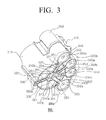
- FIG. 3 is a bottom perspective view illustrating the dust bin 300 for explaining the dust bin-water distribution passage part 300a
- FIG. 4 is a top perspective view illustrating the lower cover 400, an upper surface of which is coupled with the dust bin 300.
- the dust bin-water distribution part 300a and lower cover-water distribution part 400b will be explained in greater detail with reference with FIGS. 3 and 4 .
- the dust bin-water distribution part 300a as shown in FIG. 3 includes a plurality of ribs including a first chamber rib 310b, at least one second chamber rib 350b, and at least one water distribution passage rib 301.
- the first chamber rib 301b is projected and formed to include the first water inflow hole 313 at a bottom surface thereof.
- the first chamber rib 310b is coupled with first chamber rib groove 410b of the lower cover 400 to form a first chamber 310a.
- the second chamber ribs 350b is projected and formed to include the second water inflow holes 353 at respective bottom surface of the second dust bins 350 and to have side surface opened facing the first chamber 310a.
- the second chamber ribs 350b are coupled with the second chamber-lower ribs 450b to form second chambers 350a.
- the water distribution passage ribs 301 projected and formed to connect between the first chamber rib 301b and the second chamber ribs 350b and between the first chamber 310a and a lower area 390a of the quantity-of-water display part 390.
- the water distribution passage ribs 301 are coupled with water distribution rib grooves 401a of the lower cover 400 to form dust bin-water distribution passages 320 connecting between the first chamber 310a and the second chambers 350a and a quantity-of-water display part-water distribution passage 330 between the first chamber 310a and the lower area 390a of the quantity-of-water display part 390.
- the lower cover 400 includes the lower cover-water distribution passage part 400b including two first chamber-lower ribs 410a, a plurality of second chamber-lower ribs 450b and a plurality of lower water distribution passage ribs 401.
- the first chamber-lower ribs 410a are projected and formed in pairs to include the first water inflow hole 313 at surfaces opposite to the first water inflow hole 313, and thus forms the first chamber rib groove 410b into which the first chamber rib 310b is inserted.
- the second chamber-lower ribs 450b are projected and formed every positions facing the respective second dust bins 350 of the lower 400 thus to couple with the second chamber ribs 350b.
- the lower water distribution passage ribs 401 is configured, so that at least two pairs thereof are projected and formed between the first chamber-lower ribs 410a and the second chamber-lower ribs 450b, hereby forming at least two water distribution passage rib grooves 401a. In other ward, by inserting the water distribution ribs 301 into each of a pair of water distribution passage rib grooves 401a formed by the two pairs of lower water distribution passage ribs 401, areas therebetween form water distribution passages.
- separate sealing members may be coupled on the first chamber rib groove 410b and the water distribution passage rib grooves 401a.
- the lower cover 400 may further include a lower cover-outer circumference rib(not shown) projected upward from the whole outer circumference of the lower cover 400 to form an outer circumference rib groove (not shown ) into which an outer circumference rib 302 projected and formed to form a bottom-outer circumference surface of the dust bin 300 is inserted
- the dust bin-water distribution passage part 300a and the lower cover-water distribution passage part 400 of FIGS. 3 and 4 as described above are coupled to or with each other to form the water distribution passage part 500 of FIG. 5 .
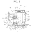
- FIG. 5 is a sectional view of the wet type dust collecting apparatus 1 taken along a line V-V of FIG. 1 .
- the dust bin 300 and the lower cover 400 are coupled to or with each other, the first chamber rib 310b is inserted into the first chamber rib groove 410b to form the first chamber 310a.
- the second chamber ribs 350b are coupled with the second chamber-lower ribs 450b to form the second chambers 350a.
- the water distribution passage ribs 301 are inserted into the water distribution passage rib grooves 401a to form the dust bin-water distribution passages 320 and the quantity-of-water display part-water distribution passage 330.
- the first chamber 310a, the second chambers 350a, the dust bin-water distribution passages 320 and the quantity-of-water display part-water distribution passage 330 formed as above form the water distribution passage part 500.
- a user can simultaneously fill the first dust bin 310, the second dust bins 350 and the quantity-of-water display part 390 with water by filling only the first dust bin 310 or any one of the second dust bins 350 with water.
- the first exhaust pipe unit 210 is coupled to a lower part of the first outlet 202 of the dust bin cover 200 to communicate with the second passage 240.
- the second inflow units 230 are coupled to portions of the bottom surface of the dust bin cover 200 in which the second inlets 231 are formed, to communicate with the second passage 240.
- the second passage cover 100 is coupled to the upper surface of the dust bin cover 200 thus to form the second passage 240 to draw the air exhausted from the first exhaust pipe unit 210, into the second inflow pipe units 230.
- the dust bin cover 200 to which the second passage cover 100 the first exhaust pipe unit 210 and the second inflow pipe units 230 are coupled closes up the upper part of the dust bin 300 to be able to open and close.
- the sealing member 220 coupled to the first exhaust pipe unit 210 blocks the first water inflow holes 313 to separate a lower area 319 of the first dust collecting area 310c and lower areas 359 of the second dust collecting areas 350c from each other.
- the wet type dust collecting apparatus 1 in which the assembling is completed is mounted in the vacuum cleaner (not shown), and then collects separated dust by using water filled in the first dust bin 310 and the second dust bins 350.
- the air drawn in the first dust bin 310 is whirled about the first exhaust pipe unit 210.
- the foreign substance such as the dust and the dirt, is separated from the air and collected in the first dust collecting area 310c of the first dust bin 310.
- the air from which the foreign substance is separated while whirling in the first dust bin 310 passes through the grill 211 and flows into the first exhaust pipe unit 210.
- the air flowed into the first exhaust pipe unit 210 moves up and then flows into the second inflow pipe units 230 through the first outlet 202, the second passage 240 and the second inlets 231.
- the air flowed into the second inflow pipe units 230 moves downward along spaces in the second inflow pipe units 230 and then flows into the second dust bins 350 through the second discharge port 232.
- the air flowed into the second dust bins 350 moves upward while whirling about the second inflow pipe units 230, and then discharges through the respective second outlets 352.
- the air discharged through the respective second outlets 352 gathers in the exhaust chamber 370 and then discharged to the vacuum cleaner.
- minute dust which is not separated from the air in the first dust bin 310, is separated and collected in the second dust collecting areas 350c of the second dust bin 350.
- the air whirling about the first exhaust pipe unit 210 and the second inflow pipe units 230 in the dust separating process as described above whirls water filled in the first dust bin 310 and the respective second dust bins 350.
- the whirling water creeps up inner a wall of the first dust bin 310 and walls of the second dust bins 350 to form a first water wall 501 and second water walls 601.
- the first wall 501 and the second water walls 601 formed as above more rapidly collects the dust separated in the first dust bin 310 and the second dust bins 350, thereby improving dust separating efficiency in the first dust bin 310 and the second dust bins 350.
- the sealing member 220 blocks or close up the first water inflow hole 313 to separate the first dust bin 310 and the second dust bins 350 form each other, thereby to prevent the water filled in the first dust bin 310 and the second dust bins 350 from being moved from the first bin 310 to the second dust bins 350 or vice versa due to a pressure difference therebetween.
- the water in the respective dust bins is maintained in a proper water level regardless of the pressure difference, thereby preventing the dust separating efficiency from being deteriorated as the water is moved from the first bin to the second dust bins or vice versa.
- the dust collecting apparatus has the plurality of dust collecting areas configured, so that the entire thereof can be filled with water through any one thereof, thereby allowing the dust collecting apparatus to improve a convenience in use.
- the dust collecting apparatus prevents the water from being moved between the dust collecting areas due to the pressure difference therebetween, thereby allowing the dust separating efficiency not to be deteriorated.
Landscapes
- Engineering & Computer Science (AREA)
- Mechanical Engineering (AREA)
- Filters For Electric Vacuum Cleaners (AREA)
Applications Claiming Priority (2)
| Application Number | Priority Date | Filing Date | Title |
|---|---|---|---|
| KR1020090043736A KR101566411B1 (ko) | 2009-05-19 | 2009-05-19 | 진공청소기의 습식집진장치 |
| PCT/KR2010/000806 WO2010134683A2 (ko) | 2009-05-19 | 2010-02-09 | 진공청소기의 습식집진장치 |
Publications (3)
| Publication Number | Publication Date |
|---|---|
| EP2433540A2 true EP2433540A2 (de) | 2012-03-28 |
| EP2433540A4 EP2433540A4 (de) | 2017-11-15 |
| EP2433540B1 EP2433540B1 (de) | 2019-07-03 |
Family
ID=43126610
Family Applications (1)
| Application Number | Title | Priority Date | Filing Date |
|---|---|---|---|
| EP10777870.6A Active EP2433540B1 (de) | 2009-05-19 | 2010-02-09 | Nass-staubsammelvorrichtung für einen staubsauger |
Country Status (3)
| Country | Link |
|---|---|
| EP (1) | EP2433540B1 (de) |
| KR (1) | KR101566411B1 (de) |
| WO (1) | WO2010134683A2 (de) |
Cited By (2)
| Publication number | Priority date | Publication date | Assignee | Title |
|---|---|---|---|---|
| US20120167772A1 (en) * | 2009-08-26 | 2012-07-05 | Samsung Electronics Co., Ltd. | Wet-type dust collector for a vacuum cleaner |
| CN110811418A (zh) * | 2019-11-26 | 2020-02-21 | 兰溪米雪电子科技有限公司 | 一种带自洁功能的吸尘器 |
Families Citing this family (1)
| Publication number | Priority date | Publication date | Assignee | Title |
|---|---|---|---|---|
| KR102629020B1 (ko) * | 2023-10-11 | 2024-01-25 | 홍준서 | 습식 청소기 |
Family Cites Families (14)
| Publication number | Priority date | Publication date | Assignee | Title |
|---|---|---|---|---|
| CA1066005A (en) | 1978-03-20 | 1979-11-13 | Fernand Lachance | Liquid aspirator |
| US4800615A (en) | 1987-04-03 | 1989-01-31 | The Scott Fetzer Company | Wet/dry vac |
| US5922093A (en) * | 1996-04-25 | 1999-07-13 | Miracle Marketing Corporation | Ultra-filtration vacuum system |
| JP3635532B2 (ja) * | 2001-05-07 | 2005-04-06 | 株式会社プランテ | 湿式清浄装置 |
| JP2003205214A (ja) | 2001-10-29 | 2003-07-22 | Gorin Sangyo:Kk | 粉塵除去方法およびその装置 |
| US7293324B2 (en) | 2003-09-19 | 2007-11-13 | Techtronic Industries Co., Ltd. | Vacuum cleaner with level control |
| JP2006006837A (ja) * | 2004-06-29 | 2006-01-12 | Izumi Products Co | 湿式電気掃除機 |
| JP4535900B2 (ja) | 2005-02-14 | 2010-09-01 | 花王株式会社 | 湿式電気掃除機 |
| KR101136631B1 (ko) * | 2005-03-19 | 2012-04-18 | 엘지전자 주식회사 | 물청소 겸용 진공청소기의 집진유니트 |
| AU2006220438B2 (en) | 2005-09-23 | 2011-02-03 | Bissell Inc. | Vacuum cleaner with two stage filtration |
| JP2007111397A (ja) * | 2005-10-24 | 2007-05-10 | Izumi Products Co | 湿式電気掃除機 |
| KR100779190B1 (ko) | 2006-06-09 | 2007-11-23 | 주식회사 대우일렉트로닉스 | 부표 및 이를 채택한 물통 |
| KR100800655B1 (ko) * | 2006-07-04 | 2008-02-01 | 김종기 | 건식 및 습식 이중필터방식 진공청소기 |
| KR100790781B1 (ko) | 2006-08-07 | 2008-01-02 | 주식회사 대우일렉트로닉스 | 스팀청소기용 물탱크 조립체 및 스팀청소기 제어방법 |
-
2009
- 2009-05-19 KR KR1020090043736A patent/KR101566411B1/ko not_active Expired - Fee Related
-
2010
- 2010-02-09 WO PCT/KR2010/000806 patent/WO2010134683A2/ko not_active Ceased
- 2010-02-09 EP EP10777870.6A patent/EP2433540B1/de active Active
Non-Patent Citations (1)
| Title |
|---|
| See references of WO2010134683A2 * |
Cited By (4)
| Publication number | Priority date | Publication date | Assignee | Title |
|---|---|---|---|---|
| US20120167772A1 (en) * | 2009-08-26 | 2012-07-05 | Samsung Electronics Co., Ltd. | Wet-type dust collector for a vacuum cleaner |
| US8920549B2 (en) * | 2009-08-26 | 2014-12-30 | Samsung Electronics Co., Ltd. | Wet-type dust collector for a vacuum cleaner |
| CN110811418A (zh) * | 2019-11-26 | 2020-02-21 | 兰溪米雪电子科技有限公司 | 一种带自洁功能的吸尘器 |
| CN110811418B (zh) * | 2019-11-26 | 2021-05-07 | 瓦柯姆(南通)吸尘器有限公司 | 一种带自洁功能的吸尘器 |
Also Published As
| Publication number | Publication date |
|---|---|
| EP2433540B1 (de) | 2019-07-03 |
| WO2010134683A3 (ko) | 2011-01-13 |
| WO2010134683A2 (ko) | 2010-11-25 |
| KR101566411B1 (ko) | 2015-11-06 |
| KR20100124627A (ko) | 2010-11-29 |
| EP2433540A4 (de) | 2017-11-15 |
Similar Documents
| Publication | Publication Date | Title |
|---|---|---|
| US7488363B2 (en) | Dust collection unit of vacuum cleaner | |
| KR101003417B1 (ko) | 진공 청소기의 집진장치 | |
| US7449039B2 (en) | Cyclonic cleaner | |
| US7395579B2 (en) | Cyclone dust collecting device and vacuum cleaner having the same | |
| EP2170144B1 (de) | Staubabscheidevorrichtung eines staubsaugers | |
| JP2004344642A (ja) | 真空掃除機の二重サイクロン集塵装置 | |
| KR101845044B1 (ko) | 집진장치 및 이를 구비하는 진공 청소기 | |
| RU2004120671A (ru) | Узел электродвигателя (варианты) и пылесос с таким узлом | |
| GB2456192A (en) | Sloped upper wall of cyclone inflow channel | |
| EP3795049B1 (de) | Staubsauger | |
| CN101073480B (zh) | 真空吸尘器 | |
| CN1981688A (zh) | 真空吸尘器 | |
| KR100732160B1 (ko) | 싸이클론 집진장치 | |
| KR20110001563A (ko) | 진공청소기의 집진장치 및 진공청소기 | |
| EP2433540B1 (de) | Nass-staubsammelvorrichtung für einen staubsauger | |
| KR100606753B1 (ko) | 다중 싸이클론 진공 청소기 | |
| KR102514500B1 (ko) | 집진장치 및 이를 구비하는 진공 청소기 | |
| EP1795102B1 (de) | Staubsauger mit Halterung für Staubfiltereinheit | |
| EP1952742A2 (de) | Motorenanordnung und Staubsauger mit derselben | |
| KR100595230B1 (ko) | 싸이클론 집진장치 | |
| KR102054419B1 (ko) | 사이클론 진공청소기 | |
| KR102081942B1 (ko) | 청소기 | |
| KR102290894B1 (ko) | 집진장치 및 이를 구비하는 진공 청소기 | |
| CN208371718U (zh) | 一种表面清洁器 | |
| CN216535180U (zh) | 一种用于清洁机的灰尘分离模块及清洁机 |
Legal Events
| Date | Code | Title | Description |
|---|---|---|---|
| PUAI | Public reference made under article 153(3) epc to a published international application that has entered the european phase |
Free format text: ORIGINAL CODE: 0009012 |
|
| 17P | Request for examination filed |
Effective date: 20111219 |
|
| AK | Designated contracting states |
Kind code of ref document: A2 Designated state(s): AT BE BG CH CY CZ DE DK EE ES FI FR GB GR HR HU IE IS IT LI LT LU LV MC MK MT NL NO PL PT RO SE SI SK SM TR |
|
| DAX | Request for extension of the european patent (deleted) | ||
| RAP1 | Party data changed (applicant data changed or rights of an application transferred) |
Owner name: SAMSUNG ELECTRONICS CO., LTD. |
|
| A4 | Supplementary search report drawn up and despatched |
Effective date: 20171016 |
|
| RIC1 | Information provided on ipc code assigned before grant |
Ipc: A47L 9/18 20060101AFI20171010BHEP |
|
| STAA | Information on the status of an ep patent application or granted ep patent |
Free format text: STATUS: EXAMINATION IS IN PROGRESS |
|
| 17Q | First examination report despatched |
Effective date: 20180717 |
|
| GRAP | Despatch of communication of intention to grant a patent |
Free format text: ORIGINAL CODE: EPIDOSNIGR1 |
|
| STAA | Information on the status of an ep patent application or granted ep patent |
Free format text: STATUS: GRANT OF PATENT IS INTENDED |
|
| INTG | Intention to grant announced |
Effective date: 20190208 |
|
| GRAS | Grant fee paid |
Free format text: ORIGINAL CODE: EPIDOSNIGR3 |
|
| GRAA | (expected) grant |
Free format text: ORIGINAL CODE: 0009210 |
|
| STAA | Information on the status of an ep patent application or granted ep patent |
Free format text: STATUS: THE PATENT HAS BEEN GRANTED |
|
| AK | Designated contracting states |
Kind code of ref document: B1 Designated state(s): AT BE BG CH CY CZ DE DK EE ES FI FR GB GR HR HU IE IS IT LI LT LU LV MC MK MT NL NO PL PT RO SE SI SK SM TR |
|
| REG | Reference to a national code |
Ref country code: GB Ref legal event code: FG4D |
|
| REG | Reference to a national code |
Ref country code: CH Ref legal event code: EP Ref country code: AT Ref legal event code: REF Ref document number: 1149961 Country of ref document: AT Kind code of ref document: T Effective date: 20190715 |
|
| REG | Reference to a national code |
Ref country code: DE Ref legal event code: R096 Ref document number: 602010059852 Country of ref document: DE |
|
| REG | Reference to a national code |
Ref country code: IE Ref legal event code: FG4D |
|
| REG | Reference to a national code |
Ref country code: NL Ref legal event code: MP Effective date: 20190703 |
|
| REG | Reference to a national code |
Ref country code: LT Ref legal event code: MG4D |
|
| REG | Reference to a national code |
Ref country code: AT Ref legal event code: MK05 Ref document number: 1149961 Country of ref document: AT Kind code of ref document: T Effective date: 20190703 |
|
| PG25 | Lapsed in a contracting state [announced via postgrant information from national office to epo] |
Ref country code: LT Free format text: LAPSE BECAUSE OF FAILURE TO SUBMIT A TRANSLATION OF THE DESCRIPTION OR TO PAY THE FEE WITHIN THE PRESCRIBED TIME-LIMIT Effective date: 20190703 Ref country code: BG Free format text: LAPSE BECAUSE OF FAILURE TO SUBMIT A TRANSLATION OF THE DESCRIPTION OR TO PAY THE FEE WITHIN THE PRESCRIBED TIME-LIMIT Effective date: 20191003 Ref country code: SE Free format text: LAPSE BECAUSE OF FAILURE TO SUBMIT A TRANSLATION OF THE DESCRIPTION OR TO PAY THE FEE WITHIN THE PRESCRIBED TIME-LIMIT Effective date: 20190703 Ref country code: NL Free format text: LAPSE BECAUSE OF FAILURE TO SUBMIT A TRANSLATION OF THE DESCRIPTION OR TO PAY THE FEE WITHIN THE PRESCRIBED TIME-LIMIT Effective date: 20190703 Ref country code: PT Free format text: LAPSE BECAUSE OF FAILURE TO SUBMIT A TRANSLATION OF THE DESCRIPTION OR TO PAY THE FEE WITHIN THE PRESCRIBED TIME-LIMIT Effective date: 20191104 Ref country code: HR Free format text: LAPSE BECAUSE OF FAILURE TO SUBMIT A TRANSLATION OF THE DESCRIPTION OR TO PAY THE FEE WITHIN THE PRESCRIBED TIME-LIMIT Effective date: 20190703 Ref country code: CZ Free format text: LAPSE BECAUSE OF FAILURE TO SUBMIT A TRANSLATION OF THE DESCRIPTION OR TO PAY THE FEE WITHIN THE PRESCRIBED TIME-LIMIT Effective date: 20190703 Ref country code: FI Free format text: LAPSE BECAUSE OF FAILURE TO SUBMIT A TRANSLATION OF THE DESCRIPTION OR TO PAY THE FEE WITHIN THE PRESCRIBED TIME-LIMIT Effective date: 20190703 Ref country code: AT Free format text: LAPSE BECAUSE OF FAILURE TO SUBMIT A TRANSLATION OF THE DESCRIPTION OR TO PAY THE FEE WITHIN THE PRESCRIBED TIME-LIMIT Effective date: 20190703 Ref country code: NO Free format text: LAPSE BECAUSE OF FAILURE TO SUBMIT A TRANSLATION OF THE DESCRIPTION OR TO PAY THE FEE WITHIN THE PRESCRIBED TIME-LIMIT Effective date: 20191003 |
|
| PG25 | Lapsed in a contracting state [announced via postgrant information from national office to epo] |
Ref country code: IS Free format text: LAPSE BECAUSE OF FAILURE TO SUBMIT A TRANSLATION OF THE DESCRIPTION OR TO PAY THE FEE WITHIN THE PRESCRIBED TIME-LIMIT Effective date: 20191103 Ref country code: LV Free format text: LAPSE BECAUSE OF FAILURE TO SUBMIT A TRANSLATION OF THE DESCRIPTION OR TO PAY THE FEE WITHIN THE PRESCRIBED TIME-LIMIT Effective date: 20190703 Ref country code: ES Free format text: LAPSE BECAUSE OF FAILURE TO SUBMIT A TRANSLATION OF THE DESCRIPTION OR TO PAY THE FEE WITHIN THE PRESCRIBED TIME-LIMIT Effective date: 20190703 Ref country code: GR Free format text: LAPSE BECAUSE OF FAILURE TO SUBMIT A TRANSLATION OF THE DESCRIPTION OR TO PAY THE FEE WITHIN THE PRESCRIBED TIME-LIMIT Effective date: 20191004 |
|
| PG25 | Lapsed in a contracting state [announced via postgrant information from national office to epo] |
Ref country code: TR Free format text: LAPSE BECAUSE OF FAILURE TO SUBMIT A TRANSLATION OF THE DESCRIPTION OR TO PAY THE FEE WITHIN THE PRESCRIBED TIME-LIMIT Effective date: 20190703 |
|
| PG25 | Lapsed in a contracting state [announced via postgrant information from national office to epo] |
Ref country code: DK Free format text: LAPSE BECAUSE OF FAILURE TO SUBMIT A TRANSLATION OF THE DESCRIPTION OR TO PAY THE FEE WITHIN THE PRESCRIBED TIME-LIMIT Effective date: 20190703 Ref country code: EE Free format text: LAPSE BECAUSE OF FAILURE TO SUBMIT A TRANSLATION OF THE DESCRIPTION OR TO PAY THE FEE WITHIN THE PRESCRIBED TIME-LIMIT Effective date: 20190703 Ref country code: RO Free format text: LAPSE BECAUSE OF FAILURE TO SUBMIT A TRANSLATION OF THE DESCRIPTION OR TO PAY THE FEE WITHIN THE PRESCRIBED TIME-LIMIT Effective date: 20190703 Ref country code: IT Free format text: LAPSE BECAUSE OF FAILURE TO SUBMIT A TRANSLATION OF THE DESCRIPTION OR TO PAY THE FEE WITHIN THE PRESCRIBED TIME-LIMIT Effective date: 20190703 Ref country code: PL Free format text: LAPSE BECAUSE OF FAILURE TO SUBMIT A TRANSLATION OF THE DESCRIPTION OR TO PAY THE FEE WITHIN THE PRESCRIBED TIME-LIMIT Effective date: 20190703 |
|
| PG25 | Lapsed in a contracting state [announced via postgrant information from national office to epo] |
Ref country code: SM Free format text: LAPSE BECAUSE OF FAILURE TO SUBMIT A TRANSLATION OF THE DESCRIPTION OR TO PAY THE FEE WITHIN THE PRESCRIBED TIME-LIMIT Effective date: 20190703 Ref country code: SK Free format text: LAPSE BECAUSE OF FAILURE TO SUBMIT A TRANSLATION OF THE DESCRIPTION OR TO PAY THE FEE WITHIN THE PRESCRIBED TIME-LIMIT Effective date: 20190703 Ref country code: IS Free format text: LAPSE BECAUSE OF FAILURE TO SUBMIT A TRANSLATION OF THE DESCRIPTION OR TO PAY THE FEE WITHIN THE PRESCRIBED TIME-LIMIT Effective date: 20200224 |
|
| REG | Reference to a national code |
Ref country code: DE Ref legal event code: R097 Ref document number: 602010059852 Country of ref document: DE |
|
| PLBE | No opposition filed within time limit |
Free format text: ORIGINAL CODE: 0009261 |
|
| STAA | Information on the status of an ep patent application or granted ep patent |
Free format text: STATUS: NO OPPOSITION FILED WITHIN TIME LIMIT |
|
| PG2D | Information on lapse in contracting state deleted |
Ref country code: IS |
|
| 26N | No opposition filed |
Effective date: 20200603 |
|
| PG25 | Lapsed in a contracting state [announced via postgrant information from national office to epo] |
Ref country code: SI Free format text: LAPSE BECAUSE OF FAILURE TO SUBMIT A TRANSLATION OF THE DESCRIPTION OR TO PAY THE FEE WITHIN THE PRESCRIBED TIME-LIMIT Effective date: 20190703 |
|
| REG | Reference to a national code |
Ref country code: DE Ref legal event code: R119 Ref document number: 602010059852 Country of ref document: DE |
|
| REG | Reference to a national code |
Ref country code: CH Ref legal event code: PL |
|
| GBPC | Gb: european patent ceased through non-payment of renewal fee |
Effective date: 20200209 |
|
| REG | Reference to a national code |
Ref country code: BE Ref legal event code: MM Effective date: 20200229 |
|
| PG25 | Lapsed in a contracting state [announced via postgrant information from national office to epo] |
Ref country code: MC Free format text: LAPSE BECAUSE OF FAILURE TO SUBMIT A TRANSLATION OF THE DESCRIPTION OR TO PAY THE FEE WITHIN THE PRESCRIBED TIME-LIMIT Effective date: 20190703 Ref country code: LU Free format text: LAPSE BECAUSE OF NON-PAYMENT OF DUE FEES Effective date: 20200209 |
|
| PG25 | Lapsed in a contracting state [announced via postgrant information from national office to epo] |
Ref country code: LI Free format text: LAPSE BECAUSE OF NON-PAYMENT OF DUE FEES Effective date: 20200229 Ref country code: CH Free format text: LAPSE BECAUSE OF NON-PAYMENT OF DUE FEES Effective date: 20200229 |
|
| PG25 | Lapsed in a contracting state [announced via postgrant information from national office to epo] |
Ref country code: FR Free format text: LAPSE BECAUSE OF NON-PAYMENT OF DUE FEES Effective date: 20200229 Ref country code: IE Free format text: LAPSE BECAUSE OF NON-PAYMENT OF DUE FEES Effective date: 20200209 Ref country code: DE Free format text: LAPSE BECAUSE OF NON-PAYMENT OF DUE FEES Effective date: 20200901 Ref country code: GB Free format text: LAPSE BECAUSE OF NON-PAYMENT OF DUE FEES Effective date: 20200209 |
|
| PG25 | Lapsed in a contracting state [announced via postgrant information from national office to epo] |
Ref country code: BE Free format text: LAPSE BECAUSE OF NON-PAYMENT OF DUE FEES Effective date: 20200229 |
|
| PG25 | Lapsed in a contracting state [announced via postgrant information from national office to epo] |
Ref country code: MT Free format text: LAPSE BECAUSE OF FAILURE TO SUBMIT A TRANSLATION OF THE DESCRIPTION OR TO PAY THE FEE WITHIN THE PRESCRIBED TIME-LIMIT Effective date: 20190703 Ref country code: CY Free format text: LAPSE BECAUSE OF FAILURE TO SUBMIT A TRANSLATION OF THE DESCRIPTION OR TO PAY THE FEE WITHIN THE PRESCRIBED TIME-LIMIT Effective date: 20190703 |
|
| PG25 | Lapsed in a contracting state [announced via postgrant information from national office to epo] |
Ref country code: MK Free format text: LAPSE BECAUSE OF FAILURE TO SUBMIT A TRANSLATION OF THE DESCRIPTION OR TO PAY THE FEE WITHIN THE PRESCRIBED TIME-LIMIT Effective date: 20190703 |