EP2433866A2 - Drahtloses Rotorverfolgungs- und -ausgleichssystem für Rotorflugzeug - Google Patents
Drahtloses Rotorverfolgungs- und -ausgleichssystem für Rotorflugzeug Download PDFInfo
- Publication number
- EP2433866A2 EP2433866A2 EP11250767A EP11250767A EP2433866A2 EP 2433866 A2 EP2433866 A2 EP 2433866A2 EP 11250767 A EP11250767 A EP 11250767A EP 11250767 A EP11250767 A EP 11250767A EP 2433866 A2 EP2433866 A2 EP 2433866A2
- Authority
- EP
- European Patent Office
- Prior art keywords
- data
- rotorcraft
- tachometer sensor
- rotating blades
- vibration
- Prior art date
- Legal status (The legal status is an assumption and is not a legal conclusion. Google has not performed a legal analysis and makes no representation as to the accuracy of the status listed.)
- Granted
Links
Images


Classifications
-
- B—PERFORMING OPERATIONS; TRANSPORTING
- B64—AIRCRAFT; AVIATION; COSMONAUTICS
- B64C—AEROPLANES; HELICOPTERS
- B64C27/00—Rotorcraft; Rotors peculiar thereto
- B64C27/008—Rotors tracking or balancing devices
Definitions
- the subject invention is directed to the field of sensing, autonomous measurement, and wireless communications, and more particularly to, the use of wireless sensors in rotorcraft Rotor Track and Balance (RTB) systems.
- RTB Rotor Track and Balance
- Wireless sensing has been steadily gaining ground in the aerospace industry.
- data is collected via a set of sensors which are remotely located from data processors.
- the sensors are connected to these data processors through a heavy harness of numerous and long wires.
- these sensors or actuators need to be situated at critical locations, such as near the aircraft engine or on rotating parts of the aircraft making it challenging, if at all possible, to rely on traditional wires and harnesses to provide power to the sensors and a communication link between the sensors and the data processor(s).
- HUMS Health and Usage Monitoring Systems
- Rotor Track and Balance a function performed by the aircraft HUMS, is the process of detecting and correcting vibrations caused by the main rotor. Vibrations caused by the helicopter main rotor are typically either in a vertical or lateral plan (with respect to the main frame of the rotorcraft) that are respectively due to unequal lift produced by the main rotor blades or to unequal distribution of mass in the main rotor "disk.” There are several reasons that can cause these types of undesired vibrations. For instance, most common causes of vertical vibration include variation between chord profiles of the blades and inadequate adjustment of pitch change links and trim tabs.
- Track data is typically acquired using an optical tracker sensor
- vibration data is acquired using accelerometers.
- rotor azimuth position sensors sometimes referred to as tachometer sensors
- the rotor track adjustment feature may be optional and the optical tracker sensor may not be always deployed.
- vibration and azimuth data alone may be used for rotor balancing only.
- RTB systems such limited installations have been also referred to as RTB systems, as they can be always temporarily expanded by addition of rotor track measurement.
- the present invention pertains primarily to the rotor balancing function of an RTB system, but is also applicable to full installations that also include the rotor track adjustment function.
- Exemplary rotor track and balance systems are illustrated in U.S. Patent Nos. 4,531,408 ; 4,112,774 ; 4,053,123 ; and 6,453,669 , each of which are herein incorporated by reference in their entirety to the extent they do not conflict with the present disclosure.
- each of the sensors used to collect data in a Rotor Track and Balance system is placed in close proximity to the main rotor and remotely from the helicopter's HUMS. Therefore, it would be advantageous to provide a wireless RTB system that overcomes the disadvantages associated with traditional wired systems (e.g., weight and cable management) and solves the challenges associated with traditional wireless systems, such as discontinuous data acquisition, data synchronization, and sensor power conservation.
- traditional wired systems e.g., weight and cable management
- the present invention is directed to a rotor track and balance system for rotorcraft that includes, inter alia, a data processing unit, a tachometer sensor and at least one accelerometer.
- the tachometer sensor is located remotely from the data processing unit and is mounted proximate to the rotating blades of the rotorcraft.
- the tachometer sensor is adapted to measure the speed and position of the rotating blades and to wirelessly transmit speed and position data to the data processor.
- the at least one accelerometer is also located remotely from the data processing unit and is preferably mounted proximate to the rotating blades of the rotorcraft.
- the vibration sensors could be positioned remotely from the rotating blades.
- RTB vibrations are measured close to the rotor blades, but on others, vibrations are measured in the cabin, far away from the blades. The idea there is to minimize vibrations perceived by the crew.
- the accelerometer locations are typically specified by the aircraft manufacturer, who decides what vibration should be minimized using the RTB system.
- Each accelerometer is adapted to measure vibration in the rotating blades and to wirelessly transmit vibration data to the data processor.
- the data processing unit synchronizes the wireless data transmitted lntermittently from the tachometer sensor and the wireless accelerometer(s) and determines necessary adjustments to be made in order to reduce the vibration anomalies in the rotor blades.
- the data collected by the tachometer sensor and the at least one accelerometer is stored in a memory device associated with the sensor/accelerometer for a period of time prior to being transmitted to the data processor.
- the duration of the storage period could be predetermined, but it need not be. It is possible to have the transmission of data from the sensors controlled by the data processing unit - i.e., data can be stored until requested. For example, when the aircraft changes the flight regime rapidly that data processing unit may know that the particular set of vibration data is too contaminated to be useful and may never request its transmission.
- the tachometer sensor and each of the at least one accelerometers can include a clock and each of the clocks are synchronized by the data processing unit.
- the tachometer sensor and each of the at least one accelerometers can include a clock, but rather than synchronizing the clocks, the data processor calculates relative correction times for all of the clocks in order to synchronize the wireless data transmitted from the tachometer sensor and the at least one wireless accelerometer.
- the rotor track and balance system further includes a Health and Usage Management System for monitoring vibration anomalies in the rotorcraft's airframe and wherein the data processor is part of the rotorcraft's HUMS.
- the entire HUMS is located onboard the rotorcraft, and in other embodiments, only a portion of the rotorcraft's HUMS in located onboard and the remainder is provided in a ground-based HUMS.
- the rotorcraft's HUMS includes a memory device for storing the data transmitted wirelessly by the tachometer sensor and at least one accelerometer.
- the sensor and accelerometers used in the system preferably include a power source.
- the wireless sensor power source is a battery.
- the power source can include an energy harvesting unit.
- the tachometer sensor and each of the at least one accelerometers include a radio utilizing a transmission protocol which can be selected from the group of 802.11, 802.15.4 or 802.16 or other similar wireless protocols.
- the rotor track and balance system can further include a backup tachometer sensor for redundancy which is located remotely from the data processing unit and mounted proximate to rotating blades of the rotorcraft.
- the back-up tachometer sensor also may be adapted to measure the speed and position of the rotating blades and transmit speed and position data to the data processor.
- the present invention is also directed to a method for tracking and balancing rotating blades of a rotorcraft, which includes, among other steps, the steps of providing a data processing unit, positioning a tachometer sensor onboard the rotorcraft remotely from the data processing unit and proximate to the rotating blades of the rotorcrart; measuring with the tachometer sensor the speed and position of the rotating blades; and transmitting wirelessly speed and position data from the tachometer sensor to the data processor.
- the method further includes the steps of: positioning at least one accelerometer onboard the rotorcraft remotely from the data processing unit and preferably proximate the rotating blades of the rotorcraft; measuring using each accelerometer vibration in the rotating blades; and transmitting wirelessly for each accelerometer vibration data to the data processor.
- the accelerometers may be mounted remotely from the rotor blades without departing from the inventive aspects of the present disclosure.
- the data processor synchronizes the wireless data transmitted from the tachometer sensor and each of the at least one wireless accelerometers; and determines the necessary adjustments to be made in order to reduce any vibration anomalies in the rotor blades.
- the method further includes the step of storing in a memory device the data collected by the tachometer sensor and the at least one accelerometer for a period of time prior to transmitting the date to the data processor.
- the presently disclosed method can include the steps of: providing the tachometer sensor and each of the at least one accelerometers with a clock; and synchronizing the clock using the data processing unit.
- the method can include the steps of: providing the tachometer sensor and each of the at least one accelerometers with a clock; and calculating using the data processor relative correction times for all of the clocks in order to synchronize the wireless data transmitted from the tachometer sensor and the at least one wireless accelerometer.
- the present invention is also directed to a track and balance system for rotating blades of a rotorcraft that includes, inter alia, a tachometer sensor, a plurality of vibration sensors and a data processor.
- the tachometer sensor is mounted proximate to the rotating blades of the rotorcraft and is adapted to measure the speed and position of the rotating blades and wirelessly transmit speed and position data.
- the plurality of vibration sensors are also mounted preferably proximate to the rotating blades of the rotorcraft and each vibration sensor is adapted to measure vibration anomalies in the rotating blades and wirelessly transmit vibration data.
- the data processor is associated with an onboard Health and Usage Management System which is adapted and configured to receive the speed and position data transmitted by the tachometer sensor and the vibration data transmitted by the plurality of vibration sensors.
- the Health and Usage Management system commands the sensors as to when data is to be acquired, when data is to be transmitted, and determines necessary adjustments to be made in order to reduce the vibration anomalies in the rotor blades.
- the data collected by the tachometer sensor and the vibration sensors is stored in a memory device for a period of time prior to being transmitted to the data processor.
- the tachometer sensor and the vibration sensors each include a clock and each clock is synchronized by the data processing unit.
- Fig. 1 is diagram illustrating the system architecture for an embodiment of the wireless RTB system of the present invention which details the communication between the wireless RTB sensors and the rotorcraft's HUMS;
- Fig. 2 is a block diagram of a wireless sensor node (acceleration or tachometerometer sensor) for use in the wireless RTB system of the present invention
- Fig. 3 is a diagram illustrating an exemplary architecture for communication between the wireless RTB system illustrated in Fig. 1 and a HUMS ground station computer;
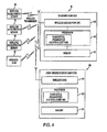
- Fig. 4 is a diagram illustrating a further exemplary architecture for communication between the wireless RTB system illustrated in Fig. 1 and a HUMS ground station computer
- RTB Wireless Rotor Track and Balance
- Figure 1 provides a diagram illustrating the system architecture for an embodiment of the wireless RTB system of the present invention, which has been designated as reference numeral 100.
- Wireless RTB system 100 includes an on-board HUMS box 50, three wireless acceleration sensors 10 and a wireless tachometer sensor 20.
- the HUMS box 50 contains, among other elements, a wireless access point (WAP) 52, a processor 54 and a memory device 56.
- WAP wireless access point
- FIG. 1 details the communication between the wireless sensors 10/20 and the rotorcraft's HUMS box 50.
- Wireless RTB system 100 acquires data from tachometerometer 20 and vibration sensors 10 over the radio waves with no wires involved to connect the sensors 10/20 to the HUMS box 50. Once track and vibration data is collected from multiple sensor locations it will be stored in memory 56 of the HUMS box 50 and consequently processed by processor 54, whether onsite (as shown) or on separate station, to recommend the corrective action to balance the main rotor system and thereby reduce vibration.
- This corrective action may include: adding defined weights to specific locations on the rotor blades, adjusting pitch control rods, or other appropriate corrections to the rotor.
- the processor 54 includes the diagnostic, prognostic and RTB algorithms for the rotorcraft's HUMS.
- the data received by the sensor in communication with the HUMS may be processed elsewhere.
- Wireless RTB system 100 consists of two basic types of sensors: a wireless tachometer sensor 20 to measure the speed and position of rotating blades and wireless accelerometers 10 to measure any vibration anomaly.
- Tachometer sensor 20 is typically placed on the main frame of the helicopter below the moving rotor assembly (i.e. swash plate) of the rotorcraft.
- the vibration accelerometers used in the RTB system are located proximate the rotating blades of the rotorcraft.
- vibrations are measured in the cabin, far away from the blades. The idea there is to minimize vibrations perceived by the crew.
- the accelerometer locations are typically specified by the aircraft manufacturer, who decides what vibration should be minimized using the RTB system.
- the turning speed and position of the blades as detected by tachometer sensor 20 provides the frequency and phase of the rotating frame which is necessary to transform the measured acceleration signals into the frequency domain, so that the transformed signals can be used by RTB algorithms to compute the optimum weights and locations on the blades or other corrective actions for the encountered vibration anomalies.
- FIG. 2 provides a schematic of a typical sensor node 40 that can be used as part of the wireless RTB system of the present invention.
- Sensor node 40 can be either a vibration sensor 10 or a tachometer sensor 20.
- the sensing node 40 contains several other blocks to enable wireless communication between the sensor node 40 and the main HUMS box 50.
- sensor node 40 includes a radio unit 44 which may use one of the commercially available radio technologies, such as IEEE 802.11, 802.15.4, 802.16, or another suitable radio protocol.
- the choice of a particular wireless protocol for the system will depend on the amount of sensor data that is required to be collected, which in turn depends on the required quality and accuracy of RTB adjustments.
- Another factor influencing selection of the radio technology may be the power consumption vs. the capacity of the available power source.
- the present inventors utilized IEEE 802.11 radio protocol which provided a high bit-rate and resulted in favorable power vs. data rate tradeoffs (i.e., it gave a minimal total energy expenditure for data transmission).
- Sensor node 40 also includes a power source 46 and a microcontroller unit 48.
- Microcontroller unit 48 processes the data recorded by the sensors and controls the functionality of other components in sensor node 40.
- Power source 46 provides the operational energy for the sensor and may be for example, a replaceable battery or an energy harvesting or scavenging unit in which energy is derived from external sources (e.g., solar power, thermal energy, wind energy, salinity gradients, and kinetic energy), and is captured, and stored.
- external sources e.g., solar power, thermal energy, wind energy, salinity gradients, and kinetic energy
- a marked difference between a wireless sensor in this invention and a wired analog sensor is that with wireless sensors it is not desirable to acquire and transmit data to the HUMS box continually, nor does the transmission of data occur simultaneously with the acquisition of data. Continuous acquisition of data would consume excessive amounts of sensor power in a wireless system.
- acquisition and storage of data is essentially simultaneous and synchronous actions.
- the wireless sensor in this invention accomplishes the acquisition and storage of data as separate actions. For example the wireless sensor acquires data corresponding to a short time interval, e.g. 10 seconds, and then transmits the data in a short burst of several data packets later in time.
- the data transmission process may last shorter or longer than the data acquisition process.
- the sensor is put into a low-power, 'sleep' state until the next data acquisition is scheduled.
- the acquisition of data is optimized for data computational performance while the transmission of data is optimized for sensor power consumption and other wireless performance goals.
- the sensor may wait 10 minutes between each two 10 second acquisitions.
- the sleep interval and acquisition interval are programmable and determined by the application.
- the system may acquire data more often, or may even start a new data acquisition while the previously acquired data portion is still in process of being sent to the HUMS box.
- the wireless RTB 100 system includes several vibration sensors 10 (accelerometers) and at least one tachometer sensor 20.
- the purpose of including a tachometerometer is to provide a common reference for all vibration data acquired by the accelerometers 10, so that the frequency of the rotating frame is known.
- all vibration data and the tachometerometer data needs to be synchronized.
- Wired sensor systems have an inherent high degree of synchronization, but wireless sensor systems do not and therefore a mechanism for synchronizing wireless data acquisition is required.
- Two main approaches may be used for synchronizing the wireless sensors used in the wireless RTB system of the present invention.
- One method is to maintain synchronized clocks running on all sensors within the system. Then, the central node of the wireless network, or the access point AP (in this case the HUMS box), may command all the sensors to acquire their next portion of sensor data at a prescribed time in future. If all sensor clocks are tightly synchronized, then the data acquisition will start at the same time, and the corresponding data sets will have the same starting times.
- Algorithms to synchronize the different sensor node clocks to each other are well known. For example, pair-wise synchronization may be used in which each sensor adjusts its clock separately to match the AP's clock. Variations on this approach may also be used without departing from the scope of the present invention.
- Another approach to the synchronization problem is to have the AP calculate relative correction terms for the clocks of all sensors in the wireless RTB system. If this is achieved, then the AP may command the sensors to acquire data at different values of their respective clocks, calculated in such a way that they all correspond to the same moment in time. Alternatively, appropriate correction and time-shifting may be performed on already collected sensor data. Such an AP-centered approach to sensor synchronization is well known.
- the net effect of including a tachometer sensor in the system architecture is that the various vibration signals may be jointly referenced to the same tachometer signal which characterizes rotation of the aircraft's rotor.
- the general architecture of the wireless RTB HUMS system including multiple wireless sensors is shown in Figure 1 .
- a single wireless sensor module may process data from more than one accelerometer and tachometer sensor.
- the figures show the simple configuration where each sensor's data is provided by a single wireless sensor module. Note that the number of wireless accelerometers included in the system may be different from that shown in the figure.
- more than one wireless tachometerometer may be used for redundancy and there may be also other sensors, wired or wireless, used in the system for other purposes, such as an optical tracker.
- the function of calculating the necessary rotor adjustments may be performed within the HUMS box, or may also be performed, fully or partially, within a separate ground-based computer, known as the HUMS ground station 100. Similar to the onboard HUMS box 50, the HUMS ground station can also include a processor 104 and memory unit 106.
- the data acquired by the HUMS box may be transferred to the ground station 100 via a wired connection 110, as shown in Figure 3 .
- This connection 110 may be an Ethernet link or another data link suitable for the system. Note that the wired connection in question would be established only temporarily, when the aircraft is on the ground, to enable transfer of the most recently acquired sensor data for further analysis. This link would be disconnected prior to the next flight.
- the RTB algorithm may be performed within the onboard HUMS box 50 and within the ground station 100.
- the HUMS box 50 may perform initial pre-processing of the data
- the ground station 100 may be responsible for user interface, accounting for user preferences regarding performing the RTB function, performing multi-objective optimization, etc.
- Other partitioning of the RTB calculations between the two modules is also possible.
- An alternative to connecting the ground station 100 to the HUMS box 50 may be through the wireless connection, as shown in Figure 4 .
- the HUMS ground station would be equipped with a wireless card 108.
- the wireless link used for this connection may be using the same protocol and wireless antenna as used by the wireless sensors.
- two different wireless technologies may be used for the sensors and for the connection to the ground station. The latter variant may be the case e.g. if data transfer from the sensors to the HUMS box in flight is subject to more stringent interference environment than the data link from the HUMS box to the HUMS ground station while the aircraft has landed.
- a removable memory module physically moved from one device to another.
- This may be a USB flash drive or another suitable memory medium.
- the sensors are wireless, but not all of the sensors need to be wireless. Moreover, some of the sensors can be powered by the aircraft and communicate wirelessly and certain sensors could be self powered. This distinction can be based on factors, such as for example, the criticality of the sensor and/or the sensor's power requirements (e.g., if the sensor is power-inefficient then a battery or using energy harvesting techniques may not provide sufficient power).
Landscapes
- Engineering & Computer Science (AREA)
- Mechanical Engineering (AREA)
- Aviation & Aerospace Engineering (AREA)
- Arrangements For Transmission Of Measured Signals (AREA)
- Length Measuring Devices With Unspecified Measuring Means (AREA)
Applications Claiming Priority (1)
| Application Number | Priority Date | Filing Date | Title |
|---|---|---|---|
| US12/924,466 US8812255B2 (en) | 2010-09-28 | 2010-09-28 | Wireless rotor track and balance system for rotorcraft |
Publications (3)
| Publication Number | Publication Date |
|---|---|
| EP2433866A2 true EP2433866A2 (de) | 2012-03-28 |
| EP2433866A3 EP2433866A3 (de) | 2015-03-25 |
| EP2433866B1 EP2433866B1 (de) | 2019-10-30 |
Family
ID=44719747
Family Applications (1)
| Application Number | Title | Priority Date | Filing Date |
|---|---|---|---|
| EP11250767.8A Active EP2433866B1 (de) | 2010-09-28 | 2011-09-09 | Drahtloses Rotorverfolgungs- und -ausgleichssystem für Rotorflugzeug |
Country Status (2)
| Country | Link |
|---|---|
| US (1) | US8812255B2 (de) |
| EP (1) | EP2433866B1 (de) |
Cited By (11)
| Publication number | Priority date | Publication date | Assignee | Title |
|---|---|---|---|---|
| CN104728055A (zh) * | 2015-03-24 | 2015-06-24 | 山西大学 | 风力发电机组偏航装置的无线状态监测系统 |
| EP2905224A1 (de) * | 2014-02-05 | 2015-08-12 | Sikorsky Aircraft Corporation | Rotorzustandssensorsystem |
| EP3002956A1 (de) * | 2014-09-30 | 2016-04-06 | Honeywell International Inc. | Netzwerk und sensortopologie eines drehflügelflugzeuges |
| EP2738090A3 (de) * | 2012-11-29 | 2017-12-13 | Sikorsky Aircraft Corporation | Drehflügelflugzeug-Blattverfolgung |
| US10403059B2 (en) | 2017-06-05 | 2019-09-03 | Honeywell International Inc. | Distributed vehicle monitoring systems and methods |
| WO2020030214A1 (de) | 2018-08-07 | 2020-02-13 | Schenck Rotec Gmbh | Messwerterfassung mit mehreren messwertaufnehmern |
| EP3653496A1 (de) * | 2018-11-16 | 2020-05-20 | Bell Helicopter Textron Inc. | Sensor zur überwachung von rotoren |
| US10979993B2 (en) | 2016-05-25 | 2021-04-13 | Ge Aviation Systems Limited | Aircraft time synchronization system |
| EP3912907A1 (de) | 2020-05-20 | 2021-11-24 | Airbus Helicopters | Verfahren und vorrichtung zur bestimmung eines zustands eines rotors eines drehflügelflugzeugs |
| WO2022157371A1 (en) * | 2021-01-25 | 2022-07-28 | Infomode Limited | Rotorcraft collision avoidance detection system |
| CN115562044A (zh) * | 2022-11-09 | 2023-01-03 | 中国航空工业集团公司上海航空测控技术研究所 | 基于hums系统的智能化旋翼锥体动平衡测试调整方法 |
Families Citing this family (18)
| Publication number | Priority date | Publication date | Assignee | Title |
|---|---|---|---|---|
| US9280516B2 (en) * | 2011-04-07 | 2016-03-08 | The University Of Western Ontario | Method and system to validate wired sensors |
| US8909453B2 (en) | 2012-01-12 | 2014-12-09 | Bell-Helicopter Textron Inc. | System and method of measuring and monitoring torque in a rotorcraft drive system |
| US10607424B2 (en) * | 2012-02-10 | 2020-03-31 | Appareo Systems, Llc | Frequency-adaptable structural health and usage monitoring system (HUMS) and method with smart sensors |
| US9758243B1 (en) | 2013-03-06 | 2017-09-12 | RMCI, Inc. | Calculation of helicopter rotor balance adjustments and coefficients using mobile devices or custom coefficients |
| EP2821873B1 (de) | 2013-07-02 | 2016-10-05 | Bell Helicopter Textron Inc. | System und Verfahren zur Bestimmung der Nutzung von Komponenten eines Hubschraubers durch Drehmoment-Messungen |
| US9243979B2 (en) * | 2014-01-14 | 2016-01-26 | Simmonds Precision Products, Inc. | System and method for adjustment response analysis |
| US9481456B2 (en) * | 2014-01-27 | 2016-11-01 | Sikorsky Aircraft Corporation | Relative acceleration blade position measurement |
| WO2015191144A2 (en) * | 2014-04-02 | 2015-12-17 | Sikorsky Aircraft Corporation | Rotor wireless load and motion monitoring sensor network |
| US9791310B2 (en) * | 2014-06-10 | 2017-10-17 | Uptime Solutions | Vibration-sensing field unit |
| US10981675B2 (en) | 2016-03-23 | 2021-04-20 | Pratt & Whitney Canada Corp. | Propeller balancing using inflight data |
| US9694915B1 (en) | 2016-03-23 | 2017-07-04 | Pratt & Whitney Canada Corp. | Propeller balancing using inflight data |
| US10878645B2 (en) * | 2017-04-19 | 2020-12-29 | Sikorsky Aircraft Corporation | Real time HUMS |
| US20190112075A1 (en) * | 2017-10-12 | 2019-04-18 | Honeywell International Inc. | Measurement synchronization methods for distributed monitoring systems |
| US11498668B2 (en) | 2020-04-22 | 2022-11-15 | Honeywell International S.R.O. | Systems and methods to perform track and balance for rotorcrafts |
| US11401043B2 (en) | 2020-06-22 | 2022-08-02 | Ge Aviation Systems Limited | Systems and methods for mobile device enabled rotor track and balance |
| US11697512B2 (en) * | 2020-10-19 | 2023-07-11 | Pratt & Whitney Canada Corp. | System and method for data recording and transmission for propeller balancing |
| FR3117588B1 (fr) * | 2020-12-14 | 2022-11-11 | Safran | Procede de surveillance d’une usure d’un actionneur |
| US20220363404A1 (en) * | 2021-05-14 | 2022-11-17 | Beta Air, Llc | Systems and methods for monitoring health of an electric vertical take-off and landing vehicle |
Citations (4)
| Publication number | Priority date | Publication date | Assignee | Title |
|---|---|---|---|---|
| US4053123A (en) | 1976-04-16 | 1977-10-11 | Chadwick-Helmuth Company, Inc. | Method and apparatus to determine need for rotor blade pitch adjustment and/or blade substitution |
| US4112774A (en) | 1977-01-07 | 1978-09-12 | Chadwick-Helmuth Company, Inc. | Aircraft rotor out-of-track correction method and apparatus |
| US4531408A (en) | 1982-12-06 | 1985-07-30 | Chadwick-Helmuth Company, Inc. | Control of rotor blade stroboscopic display |
| US6453669B2 (en) | 2000-03-03 | 2002-09-24 | The Boeing Company | Helicopter in-flight rotor tracking system, method, and smart actuator therefor |
Family Cites Families (15)
| Publication number | Priority date | Publication date | Assignee | Title |
|---|---|---|---|---|
| US4238960A (en) * | 1978-11-27 | 1980-12-16 | Lockheed Corporation | Means for balancing rotors of a machine |
| US4524620A (en) | 1983-02-07 | 1985-06-25 | Hughes Helicopters, Inc. | In-flight monitoring of composite structural components such as helicopter rotor blades |
| US5083723A (en) * | 1990-12-14 | 1992-01-28 | Teledyne Industries, Inc. | Air-driven, turbine tow reel machine controlled according to towline velocity and vent door position |
| US6415206B1 (en) | 2000-02-24 | 2002-07-02 | Simmonds Precision Products, Inc. | Method for determining a minimal set of rotor blade adjustments |
| US6768938B2 (en) * | 2001-11-16 | 2004-07-27 | Goodrich Pump & Engine Control Systems, Inc. | Vibration monitoring system for gas turbine engines |
| CA2673642C (en) * | 2007-02-28 | 2012-11-13 | John M. Lawrence | Dual rotor vertical takeoff and landing rotorcraft |
| US8050881B1 (en) * | 2007-10-18 | 2011-11-01 | Enbiomedic | Post data-collection synchronization for approximation of simultaneous data |
| US7839304B2 (en) * | 2008-05-01 | 2010-11-23 | The United States Of America As Represented By The Secretary Of The Navy | Method and system for alerting aircrew to unsafe vibration levels |
| DE102008022895B4 (de) * | 2008-05-08 | 2017-05-04 | Airbus Defence and Space GmbH | Aktiver Helikopterrotor mit verteilten Redundanzen |
| US8023443B2 (en) * | 2008-06-03 | 2011-09-20 | Simmonds Precision Products, Inc. | Wireless sensor system |
| US8210469B2 (en) * | 2008-06-27 | 2012-07-03 | Fred Nitzsche | Hybrid device for vibration control |
| US8384605B2 (en) * | 2009-02-25 | 2013-02-26 | Sikorsky Aircraft Corporation | Wireless communication between a rotating frame of reference and a non-rotating frame of reference |
| AU2010245695B2 (en) * | 2009-05-08 | 2015-03-05 | Sandvik Intellectual Property Ab | Method and system for integrating sensors on an autonomous mining drilling rig |
| US8639458B2 (en) * | 2010-02-02 | 2014-01-28 | Simmonds Precision Products, Inc. | Techniques for use with rotor track and balance to reduce vibration |
| US8279897B2 (en) * | 2010-03-02 | 2012-10-02 | Hewlett-Packard Development Company, L.P. | Synchronization in a wireless node |
-
2010
- 2010-09-28 US US12/924,466 patent/US8812255B2/en active Active
-
2011
- 2011-09-09 EP EP11250767.8A patent/EP2433866B1/de active Active
Patent Citations (4)
| Publication number | Priority date | Publication date | Assignee | Title |
|---|---|---|---|---|
| US4053123A (en) | 1976-04-16 | 1977-10-11 | Chadwick-Helmuth Company, Inc. | Method and apparatus to determine need for rotor blade pitch adjustment and/or blade substitution |
| US4112774A (en) | 1977-01-07 | 1978-09-12 | Chadwick-Helmuth Company, Inc. | Aircraft rotor out-of-track correction method and apparatus |
| US4531408A (en) | 1982-12-06 | 1985-07-30 | Chadwick-Helmuth Company, Inc. | Control of rotor blade stroboscopic display |
| US6453669B2 (en) | 2000-03-03 | 2002-09-24 | The Boeing Company | Helicopter in-flight rotor tracking system, method, and smart actuator therefor |
Cited By (17)
| Publication number | Priority date | Publication date | Assignee | Title |
|---|---|---|---|---|
| EP2738090A3 (de) * | 2012-11-29 | 2017-12-13 | Sikorsky Aircraft Corporation | Drehflügelflugzeug-Blattverfolgung |
| EP2905224A1 (de) * | 2014-02-05 | 2015-08-12 | Sikorsky Aircraft Corporation | Rotorzustandssensorsystem |
| EP3002956A1 (de) * | 2014-09-30 | 2016-04-06 | Honeywell International Inc. | Netzwerk und sensortopologie eines drehflügelflugzeuges |
| US9485605B2 (en) | 2014-09-30 | 2016-11-01 | Honeywell International Inc. | Network and sensor topology for a rotorcraft |
| CN104728055B (zh) * | 2015-03-24 | 2017-12-05 | 山西大学 | 风力发电机组偏航装置的无线状态监测系统 |
| CN104728055A (zh) * | 2015-03-24 | 2015-06-24 | 山西大学 | 风力发电机组偏航装置的无线状态监测系统 |
| US10979993B2 (en) | 2016-05-25 | 2021-04-13 | Ge Aviation Systems Limited | Aircraft time synchronization system |
| US10403059B2 (en) | 2017-06-05 | 2019-09-03 | Honeywell International Inc. | Distributed vehicle monitoring systems and methods |
| WO2020030214A1 (de) | 2018-08-07 | 2020-02-13 | Schenck Rotec Gmbh | Messwerterfassung mit mehreren messwertaufnehmern |
| EP3653496A1 (de) * | 2018-11-16 | 2020-05-20 | Bell Helicopter Textron Inc. | Sensor zur überwachung von rotoren |
| US11034438B2 (en) | 2018-11-16 | 2021-06-15 | Textron Innovations Inc. | Sensor for monitoring rotors |
| US11560220B2 (en) | 2018-11-16 | 2023-01-24 | Textron Innovations Inc. | Sensor for monitoring rotors |
| EP3912907A1 (de) | 2020-05-20 | 2021-11-24 | Airbus Helicopters | Verfahren und vorrichtung zur bestimmung eines zustands eines rotors eines drehflügelflugzeugs |
| FR3110546A1 (fr) * | 2020-05-20 | 2021-11-26 | Airbus Helicopters | Procédé et dispositif de détermination d’un état d’un rotor d’un giravion. |
| US12049303B2 (en) | 2020-05-20 | 2024-07-30 | Airbus Helicopters | Method and device for determining a state of a rotorcraft rotor |
| WO2022157371A1 (en) * | 2021-01-25 | 2022-07-28 | Infomode Limited | Rotorcraft collision avoidance detection system |
| CN115562044A (zh) * | 2022-11-09 | 2023-01-03 | 中国航空工业集团公司上海航空测控技术研究所 | 基于hums系统的智能化旋翼锥体动平衡测试调整方法 |
Also Published As
| Publication number | Publication date |
|---|---|
| EP2433866A3 (de) | 2015-03-25 |
| US8812255B2 (en) | 2014-08-19 |
| US20120078544A1 (en) | 2012-03-29 |
| EP2433866B1 (de) | 2019-10-30 |
Similar Documents
| Publication | Publication Date | Title |
|---|---|---|
| US8812255B2 (en) | Wireless rotor track and balance system for rotorcraft | |
| US11745876B2 (en) | Method for adaptive mission execution on an unmanned aerial vehicle | |
| CA2983208C (en) | Method of correcting rotor imbalance and wind turbine thereof | |
| US9342481B2 (en) | Systems and methods for monitoring health of vibration damping components | |
| CN111472943B (zh) | 一种风电机组高同步精度的分布式测量系统及方法 | |
| EP3413273B1 (de) | System und verfahren für verteilte überwachung von fahrzeugen | |
| EP3281491B1 (de) | Drahtlossensorsystem für ein fahrzeug und fernsteuersystem | |
| EP3473994B1 (de) | Messsynchronisationsverfahren für verteilte überwachungssysteme | |
| EP3056434B1 (de) | Selbstreferenzierende sensoren für flugzeugüberwachung | |
| US20130245879A1 (en) | Method and system for monitoring a structure | |
| EP2696185A2 (de) | Systeme und Verfahren zur Bestimmung der Navigationszustände einer Plattform | |
| JP2013527637A (ja) | 無線センサ同期化方法 | |
| EP2628126A2 (de) | Systeme und verfahren für energiesparende drahtlose erfassung mit situationsbewusstsein | |
| US20090211381A1 (en) | Roving wireless sensor and method for use in a vehicle health and usage monitoring system | |
| EP2829697B1 (de) | System und Verfahren zur Detektion der Zugabe von Motorschmiermittel | |
| JP2019163028A (ja) | 特定の飛行状態を支援するために航空機の複数のエンジンによって生成される推力を制御するための方法及びシステム | |
| GB2623795A (en) | A tire monitoring device | |
| EP3618508B1 (de) | System und verfahren zur verwaltung der batterielebensdauer in redundanten drahtlosen sensoren | |
| EP3126233B1 (de) | Rotor mit drahtlosem last- und bewegungsüberwachungssensornetzwerk | |
| JP6884081B2 (ja) | 航空機のセンサシステム | |
| CN212615177U (zh) | 一种风电机组高同步精度的分布式测量系统 | |
| KR100850896B1 (ko) | 무인 헬기의 비행 데이터 획득 시스템 및 방법 | |
| Slegers et al. | High fidelity in-flight pressure and inertial canopy sensing | |
| EP4495009A1 (de) | Verfahren zur unterstützung der steuerung eines drehflüglers und drehflügler damit | |
| CN119247368A (zh) | 一种海床基定位授时与数据回收系统及方法 |
Legal Events
| Date | Code | Title | Description |
|---|---|---|---|
| PUAI | Public reference made under article 153(3) epc to a published international application that has entered the european phase |
Free format text: ORIGINAL CODE: 0009012 |
|
| 17P | Request for examination filed |
Effective date: 20110922 |
|
| AK | Designated contracting states |
Kind code of ref document: A2 Designated state(s): AL AT BE BG CH CY CZ DE DK EE ES FI FR GB GR HR HU IE IS IT LI LT LU LV MC MK MT NL NO PL PT RO RS SE SI SK SM TR |
|
| AX | Request for extension of the european patent |
Extension state: BA ME |
|
| PUAL | Search report despatched |
Free format text: ORIGINAL CODE: 0009013 |
|
| AK | Designated contracting states |
Kind code of ref document: A3 Designated state(s): AL AT BE BG CH CY CZ DE DK EE ES FI FR GB GR HR HU IE IS IT LI LT LU LV MC MK MT NL NO PL PT RO RS SE SI SK SM TR |
|
| AX | Request for extension of the european patent |
Extension state: BA ME |
|
| RIC1 | Information provided on ipc code assigned before grant |
Ipc: G01M 1/22 20060101ALI20150213BHEP Ipc: B64C 27/00 20060101AFI20150213BHEP |
|
| 17Q | First examination report despatched |
Effective date: 20160531 |
|
| STAA | Information on the status of an ep patent application or granted ep patent |
Free format text: STATUS: EXAMINATION IS IN PROGRESS |
|
| GRAP | Despatch of communication of intention to grant a patent |
Free format text: ORIGINAL CODE: EPIDOSNIGR1 |
|
| STAA | Information on the status of an ep patent application or granted ep patent |
Free format text: STATUS: GRANT OF PATENT IS INTENDED |
|
| INTG | Intention to grant announced |
Effective date: 20190320 |
|
| GRAS | Grant fee paid |
Free format text: ORIGINAL CODE: EPIDOSNIGR3 |
|
| GRAA | (expected) grant |
Free format text: ORIGINAL CODE: 0009210 |
|
| STAA | Information on the status of an ep patent application or granted ep patent |
Free format text: STATUS: THE PATENT HAS BEEN GRANTED |
|
| AK | Designated contracting states |
Kind code of ref document: B1 Designated state(s): AL AT BE BG CH CY CZ DE DK EE ES FI FR GB GR HR HU IE IS IT LI LT LU LV MC MK MT NL NO PL PT RO RS SE SI SK SM TR |
|
| REG | Reference to a national code |
Ref country code: GB Ref legal event code: FG4D |
|
| REG | Reference to a national code |
Ref country code: CH Ref legal event code: EP |
|
| REG | Reference to a national code |
Ref country code: AT Ref legal event code: REF Ref document number: 1195871 Country of ref document: AT Kind code of ref document: T Effective date: 20191115 |
|
| REG | Reference to a national code |
Ref country code: DE Ref legal event code: R096 Ref document number: 602011063024 Country of ref document: DE |
|
| REG | Reference to a national code |
Ref country code: IE Ref legal event code: FG4D |
|
| REG | Reference to a national code |
Ref country code: LT Ref legal event code: MG4D |
|
| PG25 | Lapsed in a contracting state [announced via postgrant information from national office to epo] |
Ref country code: NO Free format text: LAPSE BECAUSE OF FAILURE TO SUBMIT A TRANSLATION OF THE DESCRIPTION OR TO PAY THE FEE WITHIN THE PRESCRIBED TIME-LIMIT Effective date: 20200130 Ref country code: LT Free format text: LAPSE BECAUSE OF FAILURE TO SUBMIT A TRANSLATION OF THE DESCRIPTION OR TO PAY THE FEE WITHIN THE PRESCRIBED TIME-LIMIT Effective date: 20191030 Ref country code: BG Free format text: LAPSE BECAUSE OF FAILURE TO SUBMIT A TRANSLATION OF THE DESCRIPTION OR TO PAY THE FEE WITHIN THE PRESCRIBED TIME-LIMIT Effective date: 20200130 Ref country code: PL Free format text: LAPSE BECAUSE OF FAILURE TO SUBMIT A TRANSLATION OF THE DESCRIPTION OR TO PAY THE FEE WITHIN THE PRESCRIBED TIME-LIMIT Effective date: 20191030 Ref country code: GR Free format text: LAPSE BECAUSE OF FAILURE TO SUBMIT A TRANSLATION OF THE DESCRIPTION OR TO PAY THE FEE WITHIN THE PRESCRIBED TIME-LIMIT Effective date: 20200131 Ref country code: LV Free format text: LAPSE BECAUSE OF FAILURE TO SUBMIT A TRANSLATION OF THE DESCRIPTION OR TO PAY THE FEE WITHIN THE PRESCRIBED TIME-LIMIT Effective date: 20191030 Ref country code: FI Free format text: LAPSE BECAUSE OF FAILURE TO SUBMIT A TRANSLATION OF THE DESCRIPTION OR TO PAY THE FEE WITHIN THE PRESCRIBED TIME-LIMIT Effective date: 20191030 Ref country code: SE Free format text: LAPSE BECAUSE OF FAILURE TO SUBMIT A TRANSLATION OF THE DESCRIPTION OR TO PAY THE FEE WITHIN THE PRESCRIBED TIME-LIMIT Effective date: 20191030 Ref country code: ES Free format text: LAPSE BECAUSE OF FAILURE TO SUBMIT A TRANSLATION OF THE DESCRIPTION OR TO PAY THE FEE WITHIN THE PRESCRIBED TIME-LIMIT Effective date: 20191030 Ref country code: PT Free format text: LAPSE BECAUSE OF FAILURE TO SUBMIT A TRANSLATION OF THE DESCRIPTION OR TO PAY THE FEE WITHIN THE PRESCRIBED TIME-LIMIT Effective date: 20200302 Ref country code: NL Free format text: LAPSE BECAUSE OF FAILURE TO SUBMIT A TRANSLATION OF THE DESCRIPTION OR TO PAY THE FEE WITHIN THE PRESCRIBED TIME-LIMIT Effective date: 20191030 |
|
| REG | Reference to a national code |
Ref country code: NL Ref legal event code: MP Effective date: 20191030 |
|
| PG25 | Lapsed in a contracting state [announced via postgrant information from national office to epo] |
Ref country code: IS Free format text: LAPSE BECAUSE OF FAILURE TO SUBMIT A TRANSLATION OF THE DESCRIPTION OR TO PAY THE FEE WITHIN THE PRESCRIBED TIME-LIMIT Effective date: 20200229 Ref country code: HR Free format text: LAPSE BECAUSE OF FAILURE TO SUBMIT A TRANSLATION OF THE DESCRIPTION OR TO PAY THE FEE WITHIN THE PRESCRIBED TIME-LIMIT Effective date: 20191030 Ref country code: RS Free format text: LAPSE BECAUSE OF FAILURE TO SUBMIT A TRANSLATION OF THE DESCRIPTION OR TO PAY THE FEE WITHIN THE PRESCRIBED TIME-LIMIT Effective date: 20191030 |
|
| PG25 | Lapsed in a contracting state [announced via postgrant information from national office to epo] |
Ref country code: AL Free format text: LAPSE BECAUSE OF FAILURE TO SUBMIT A TRANSLATION OF THE DESCRIPTION OR TO PAY THE FEE WITHIN THE PRESCRIBED TIME-LIMIT Effective date: 20191030 |
|
| PG25 | Lapsed in a contracting state [announced via postgrant information from national office to epo] |
Ref country code: DK Free format text: LAPSE BECAUSE OF FAILURE TO SUBMIT A TRANSLATION OF THE DESCRIPTION OR TO PAY THE FEE WITHIN THE PRESCRIBED TIME-LIMIT Effective date: 20191030 Ref country code: CZ Free format text: LAPSE BECAUSE OF FAILURE TO SUBMIT A TRANSLATION OF THE DESCRIPTION OR TO PAY THE FEE WITHIN THE PRESCRIBED TIME-LIMIT Effective date: 20191030 Ref country code: RO Free format text: LAPSE BECAUSE OF FAILURE TO SUBMIT A TRANSLATION OF THE DESCRIPTION OR TO PAY THE FEE WITHIN THE PRESCRIBED TIME-LIMIT Effective date: 20191030 Ref country code: EE Free format text: LAPSE BECAUSE OF FAILURE TO SUBMIT A TRANSLATION OF THE DESCRIPTION OR TO PAY THE FEE WITHIN THE PRESCRIBED TIME-LIMIT Effective date: 20191030 |
|
| REG | Reference to a national code |
Ref country code: DE Ref legal event code: R097 Ref document number: 602011063024 Country of ref document: DE |
|
| REG | Reference to a national code |
Ref country code: AT Ref legal event code: MK05 Ref document number: 1195871 Country of ref document: AT Kind code of ref document: T Effective date: 20191030 |
|
| PG25 | Lapsed in a contracting state [announced via postgrant information from national office to epo] |
Ref country code: IT Free format text: LAPSE BECAUSE OF FAILURE TO SUBMIT A TRANSLATION OF THE DESCRIPTION OR TO PAY THE FEE WITHIN THE PRESCRIBED TIME-LIMIT Effective date: 20191030 Ref country code: SM Free format text: LAPSE BECAUSE OF FAILURE TO SUBMIT A TRANSLATION OF THE DESCRIPTION OR TO PAY THE FEE WITHIN THE PRESCRIBED TIME-LIMIT Effective date: 20191030 Ref country code: SK Free format text: LAPSE BECAUSE OF FAILURE TO SUBMIT A TRANSLATION OF THE DESCRIPTION OR TO PAY THE FEE WITHIN THE PRESCRIBED TIME-LIMIT Effective date: 20191030 |
|
| PLBE | No opposition filed within time limit |
Free format text: ORIGINAL CODE: 0009261 |
|
| STAA | Information on the status of an ep patent application or granted ep patent |
Free format text: STATUS: NO OPPOSITION FILED WITHIN TIME LIMIT |
|
| 26N | No opposition filed |
Effective date: 20200731 |
|
| PG25 | Lapsed in a contracting state [announced via postgrant information from national office to epo] |
Ref country code: AT Free format text: LAPSE BECAUSE OF FAILURE TO SUBMIT A TRANSLATION OF THE DESCRIPTION OR TO PAY THE FEE WITHIN THE PRESCRIBED TIME-LIMIT Effective date: 20191030 Ref country code: SI Free format text: LAPSE BECAUSE OF FAILURE TO SUBMIT A TRANSLATION OF THE DESCRIPTION OR TO PAY THE FEE WITHIN THE PRESCRIBED TIME-LIMIT Effective date: 20191030 |
|
| PG25 | Lapsed in a contracting state [announced via postgrant information from national office to epo] |
Ref country code: MC Free format text: LAPSE BECAUSE OF FAILURE TO SUBMIT A TRANSLATION OF THE DESCRIPTION OR TO PAY THE FEE WITHIN THE PRESCRIBED TIME-LIMIT Effective date: 20191030 |
|
| REG | Reference to a national code |
Ref country code: CH Ref legal event code: PL |
|
| REG | Reference to a national code |
Ref country code: BE Ref legal event code: MM Effective date: 20200930 |
|
| PG25 | Lapsed in a contracting state [announced via postgrant information from national office to epo] |
Ref country code: LU Free format text: LAPSE BECAUSE OF NON-PAYMENT OF DUE FEES Effective date: 20200909 |
|
| PG25 | Lapsed in a contracting state [announced via postgrant information from national office to epo] |
Ref country code: BE Free format text: LAPSE BECAUSE OF NON-PAYMENT OF DUE FEES Effective date: 20200930 Ref country code: CH Free format text: LAPSE BECAUSE OF NON-PAYMENT OF DUE FEES Effective date: 20200930 Ref country code: LI Free format text: LAPSE BECAUSE OF NON-PAYMENT OF DUE FEES Effective date: 20200930 Ref country code: IE Free format text: LAPSE BECAUSE OF NON-PAYMENT OF DUE FEES Effective date: 20200909 |
|
| PG25 | Lapsed in a contracting state [announced via postgrant information from national office to epo] |
Ref country code: TR Free format text: LAPSE BECAUSE OF FAILURE TO SUBMIT A TRANSLATION OF THE DESCRIPTION OR TO PAY THE FEE WITHIN THE PRESCRIBED TIME-LIMIT Effective date: 20191030 Ref country code: MT Free format text: LAPSE BECAUSE OF FAILURE TO SUBMIT A TRANSLATION OF THE DESCRIPTION OR TO PAY THE FEE WITHIN THE PRESCRIBED TIME-LIMIT Effective date: 20191030 Ref country code: CY Free format text: LAPSE BECAUSE OF FAILURE TO SUBMIT A TRANSLATION OF THE DESCRIPTION OR TO PAY THE FEE WITHIN THE PRESCRIBED TIME-LIMIT Effective date: 20191030 |
|
| PG25 | Lapsed in a contracting state [announced via postgrant information from national office to epo] |
Ref country code: MK Free format text: LAPSE BECAUSE OF FAILURE TO SUBMIT A TRANSLATION OF THE DESCRIPTION OR TO PAY THE FEE WITHIN THE PRESCRIBED TIME-LIMIT Effective date: 20191030 |
|
| PGFP | Annual fee paid to national office [announced via postgrant information from national office to epo] |
Ref country code: DE Payment date: 20250820 Year of fee payment: 15 |
|
| PGFP | Annual fee paid to national office [announced via postgrant information from national office to epo] |
Ref country code: GB Payment date: 20250820 Year of fee payment: 15 |
|
| PGFP | Annual fee paid to national office [announced via postgrant information from national office to epo] |
Ref country code: FR Payment date: 20250820 Year of fee payment: 15 |