EP2434071A2 - Höhenverstellbare Bodenstütze - Google Patents
Höhenverstellbare Bodenstütze Download PDFInfo
- Publication number
- EP2434071A2 EP2434071A2 EP11182487A EP11182487A EP2434071A2 EP 2434071 A2 EP2434071 A2 EP 2434071A2 EP 11182487 A EP11182487 A EP 11182487A EP 11182487 A EP11182487 A EP 11182487A EP 2434071 A2 EP2434071 A2 EP 2434071A2
- Authority
- EP
- European Patent Office
- Prior art keywords
- interlocking members
- floor support
- interlocking
- riser
- tab
- Prior art date
- Legal status (The legal status is an assumption and is not a legal conclusion. Google has not performed a legal analysis and makes no representation as to the accuracy of the status listed.)
- Granted
Links
Images



Classifications
-
- E—FIXED CONSTRUCTIONS
- E04—BUILDING
- E04F—FINISHING WORK ON BUILDINGS, e.g. STAIRS, FLOORS
- E04F15/00—Flooring
- E04F15/02—Flooring or floor layers composed of a number of similar elements
- E04F15/024—Sectional false floors, e.g. computer floors
- E04F15/02447—Supporting structures
- E04F15/02464—Height adjustable elements for supporting the panels or a panel-supporting framework
- E04F15/0247—Screw jacks
- E04F15/02482—Screw jacks with a variable angle between panel and support
-
- E—FIXED CONSTRUCTIONS
- E04—BUILDING
- E04H—BUILDINGS OR LIKE STRUCTURES FOR PARTICULAR PURPOSES; SWIMMING OR SPLASH BATHS OR POOLS; MASTS; FENCING; TENTS OR CANOPIES, IN GENERAL
- E04H15/00—Tents or canopies, in general
- E04H15/32—Parts, components, construction details, accessories, interior equipment, specially adapted for tents, e.g. guy-line equipment, skirts, thresholds
- E04H15/56—Floors
Definitions
- This invention relates to a height-adjustable floor support, for example for use with temporary structures.
- Temporary floor structures are commonly used in combination with marquees.
- a rudimentary technique is employed which involves placing undedicated pieces of wood beneath the floor to adjust the height thereof.
- Such a technique is time-consuming and unreliable.
- a modern marquee is far removed from the traditional image of a tent held by fixing pegs; today a marquee is a self-supporting structure which can have all the facilities of a conventional building, including heating and running water. There is, therefore, a demand for a modern floor support to match the other features of such marquees.
- a height-adjustable floor support comprising: a baseplate assembly including first interlocking members; an adapter plate for engaging with a flooring component and including second interlocking members; and at least one riser including second interlocking members releasably interlocking with the first interlocking members of the baseplate assembly and including first interlocking members, axially spaced from the second interlocking members of the riser, for releasably interlocking with the second interlocking members of the adapter plate.
- the floor support may include a plurality of the risers. At least some of the risers may have different axial lengths.
- the baseplate assembly may be provided with apertures for use in securing the baseplate assembly to a ground surface.
- the first interlocking members of the baseplate assembly may be mounted to be positioned at a range of angles relative to the baseplate.
- the first interlocking members of the baseplate assembly may be provided in a plate spaced from a baseplate of the assembly.
- the first and second interlocking members may be engaged and disengaged by rotating one set of interlocking members about the axial direction relative to the other set of interlocking members.
- first and second sets of interlocking members may include a bayonet assembly.
- first and second interlocking members may be interlocked by means of a screw thread.
- first interlocking members may be diametrically opposed.
- the first interlocking members may comprise a tab which may extend in the axial direction of the riser and which is formed with a neck portion, for example adjacent to the bottom plate.
- the tab may extend in at least one of a radially inner and a radially outer direction.
- the or each free end of the tab may be mitred or rounded to facilitate insertion.
- the or each riser may include a peripheral wall mounted between first and second end plates, one of which end plates is provided with the first interlocking members and the other of which is provided with the second interlocking members.
- the peripheral wall may include apertures which may extend from one end plate to the other end plate.
- the peripheral wall may be arcuate, for example, cylindrical, or may be polygonal. The polygonal regions may be arranged such that two planar regions of the peripheral wall are diametrically opposed.
- the end plate including the first interlocking members may be provided with an axially extending peripheral flange which may extend at least the axial extent of the tabs.
- the second interlocking members may be in the form of apertures formed in one of the end plates, the apertures being configured with a portion of relatively large dimensions to allow the tab of the first interlocking members to pass through in an axial direction, and a further, preferably arcuate, portion which extends in a circumferential direction and which is dimensioned to allow the neck portion of the tab to pass along the circumferentially-extending portion but which does not allow the tab to pass through in an axial direction.
- the circumferentially-extending portion of the second interlocking members may be formed at that end thereof remote from the relatively large portion with an intermediate circumferentially-extending projection to limit circumferential movement of the first interlocking member relative to the second interlocking member.
- the aperture may be formed with a tab which is bent out of the plane of the aperture to inhibit rotation relative to an adjacent riser.
- Two or four second interlocking members may be provided equally spaced around a circle.
- the adapter plate may comprise a channel member which includes upright flanges provided with apertures to allow the adapter plate to be secured to a flooring component of a temporary floor structure.
- the adapter plate may include an axially extending flange extending around the second interlocking members provided thereon.
- the adapter plate may be mounted by way of a threaded elevating mechanism.
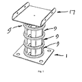
- Figure 1 is a perspective view of one embodiment of a height-adjustable floor support according to the present invention
- Figure 2 is an exploded view of the floor support shown in Figure 1 ;
- Figure 3 is a perspective view of a baseplate assembly forming part of the floor support shown in Figure 1 ;
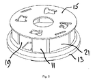
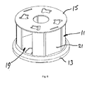
- Figures 4 , 5 and 6 are perspective views of a range of risers forming part of the height-adjustable floor support according to the present invention
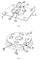
- Figure 7 is a perspective view of a bottom plate forming part of the risers shown in Figures 4 to 6 ;
- Figure 8 is a perspective view of a top plate forming part of the risers shown in Figures 4 to 6 ;
- Figure 9 is a perspective view from above of an adapter plate forming part of the floor support shown in Figure 1 ;
- Figure 10 is a perspective view from below of the adapter plate of Figure 9 ;
- Figure 11 is a perspective view of an alternative form of top plate
- Figure 12 is a perspective view of an alternative form of bottom plate for use with the top plate of Figure 11 ;
- Figure 13 shows a threaded elevating mechanism
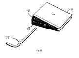
- Figures 14 and 15 show how a baseplate may be modified to operate at a range of different angles.
- the height-adjustable floor support shown in Figures 1 to 10 comprises a baseplate assembly 1 which comprises a baseplate 3 provided with apertures 5 for use in securing the baseplate assembly to a ground surface, for example by means of stakes (not shown), and a retaining mechanism 7 for receiving and retaining a riser as will be explained in more detail hereinafter.
- a riser 9 is mounted on the baseplate 1 and secured in position by the retaining mechanism 7, the riser 9 including a peripheral wall 11 mounted between a bottom plate 13 and a top plate 15. The riser will be described in more detail hereinafter.
- An adapter plate 17 is mounted on the top of the, or the upper, riser, again as will be explained in more detail hereinafter.
- the floor supports allow a temporary floor to be elevated above ground level, allowing for a basement-type configuration.
- Each riser 9 comprises a peripheral wall 11 which may be incomplete, for example including apertures 19 which may extend from an upper end to a lower end (as shown in the drawings) of the wall. Additionally, the wall is not necessarily arcuate, but may be polygonal in plan view as shown in the figures. The apertures and polygonal regions may be arranged such that two planar regions 21 of the peripheral wall are preferably diametrically opposed. The apertures and the planar regions allow the riser to be gripped, either manually or by means of a tool, in order to rotate the riser.
- the peripheral wall 11 may be of different axial lengths as shown in Figures 4 , 5 and 6 to provide different heights. If desired, however, the peripheral wall may simply be in the form of a hollow cylinder.
- the bottom plate 13 of each riser 9 is designed with a pair of diametrically opposed interlocking members 23 which engage with a complementary interlocking member formed in the top plate of each riser and in the retaining mechanism of the baseplate assembly 1.
- the bottom plate additionally includes a central aperture 25.
- the interlocking members 23 comprise a tab 27 which may extend substantially at right angles to the plane of the bottom plate (or in the axial direction of the peripheral wall) and which is formed with a neck portion 29, for example adjacent to the bottom plate. The free ends of the tab 27 may be mitred or rounded to facilitate insertion.
- the bottom plate 13 is also provided with an axially extending peripheral flange 31 (or skirt) which extends at least the axial extent of the tabs 27 to protect the same. Of course, a greater number of interlocking members may be provided if desired.
- the top plate 15 of each riser 9 is designed with four interlocking members 33 equally spaced around a circle, although in practice the number of interlocking members 33 will correspond to the number of interlocking members 23 of the bottom plate 13 or a multiple thereof.
- the top plate additionally includes a central aperture 41.
- the interlocking members 33 are in the form of apertures formed in the top plate, the apertures having a keyhole configuration with a portion 35 of relatively large dimensions to allow the tab 27 of the bottom plate to pass through in an axial direction, and an arcuate portion 37 which extends in a circumferential direction and which is dimensioned to allow the neck portion 29 of the tab 27 to pass along the arcuate portion but which does not allow the tab to pass through in an axial direction.
- the top plate 15 of one riser 9 can be securely mounted to a bottom plate of an adjoining riser.
- the arcuate portion of the interlocking members 33 is formed at that end thereof remote from the portion 35 with an intermediate circumferentially extending projection 39 which limits circumferential movement of the interlocking member 23 relative to the interlocking member 33 and reduces the likelihood of the interlocking member 23 becoming jammed in the interlocking member 33.
- the retaining mechanism 7 of the baseplate assembly 1 comprises a sheet 43 spaced from the baseplate 3 and formed with a central aperture 45 and with interlocking members 47 which correspond to the interlocking members 33 of the top plate 15 of the risers so as to allow a riser 9 to be securely mounted on the baseplate assembly 1 in the same manner as the riser would be mounted on a further riser.
- the adapter plate 17 comprises a channel member 49 which includes upright flanges 51 provided with apertures 53 to allow users to secure the floor support to a floor component (not shown) of a temporary floor structure.
- a retaining mechanism 55 is secured to the underside of the channel member 49 and is essentially the same as the bottom plate 13 of a riser.
- the retaining mechanism 55 includes diametrically opposed interlocking members 57, equal in number and location to the interlocking members 23 of the bottom plate of a riser, and which engage with a complementary interlocking member 33 formed in the top plate of each riser 9 or in the retaining mechanism of the baseplate assembly 1.
- the interlocking members 55 of the adapter plate are of substantially the same configuration as the interlocking members of the riser bottom plate 13 and will not be described further.
- the retaining mechanism 55 also includes an axially extending flange 59 (or skirt) which extends at least the axial extent of the tabs 27 to protect the same.
- the configuration of the channel member 49 may be modified,
- the components may be made of any suitable material, such as coated mild steel or stainless steel, suitable for an outdoor environment.
- the floor support may also be used indoors.
- the floor support according to the present invention is employed by mounting a baseplate assembly 1 to a ground surface and securely mounting a riser 9 of selected axial extent to the baseplate assembly by engaging the interlocking members 23, 47 and rotating the riser a few degrees relative to the baseplate assembly.
- One or more further risers may be securely mounted one by one on the riser beneath, again by engaging the interlocking members 33, 23 and rotating the riser 9 a few degrees relative to the riser below.
- an adapter plate 17 is securely mounted on the assembly beneath by engaging the interlocking members 55, 47 or 55, 33 and rotating the locking plate a few degrees relative to the assembly beneath. Disassembly of the floor support is the reverse of the assembly method.
- interlocking members may be employed to those described above.
- interlocking members incorporating a bayonet mechanism in which a centrally located tab on one component engages with a suitable aperture provided in an adjacent component, or a screw thread in which one component is threaded onto an adjacent component by means rotating one component a few degrees relative to the other component in the manner of a lid of a glass jar.
- the height-adjustable floor support may be modified in a number of ways.
- the interlocking members 33 of the top plate 15 may be provided with a tab 61 within the aperture of the interlocking member, the tab 61 being bent out of the plane of the aperture to act as an anti-rotational feature when the bottom plate 13 of an adjoining riser 9 engages with the top plate 15. That is, the tab 61 inhibits rotation in a direction towards the tab.
- the interlocking members 23 of the bottom plate 13 of a riser may be formed with a tab 63 which, unlike the tabs 27 which extend both radially inwardly and radially outwardly, extends only in a single radial direction, that is, radially outwardly as shown in Figure 12 .
- the keyhole configuration for the apertures in the top plate is not essential, provided a portion of a radially inner or radially outer side wall (radially outer as shown in Figure 11 ) is configured so as to allow the tab 63 (or tab 27) to engage beneath the top plate.
- the radially outer wall has a shorter circumferential extent than the radially inner wall and also a shorter circumferential extent than a radially intermediate portion of the aperture such that the tab 63 can engage beneath the top plate.
- both the radially outer and radially inner walls of the aperture are reduced in circumferential extent compared with a radially intermediate portion of the aperture so as to give rise to the keyhole configuration.
- the retaining mechanism 55 may be separated from the adapter plate 17 by way of a threaded elevating mechanism 65 which comprises a threaded member 67 with a rotatable member 69 mounted thereon and rotatable so as to cause the retaining mechanism to move towards and away from the adapter plate 17 in an axial direction of the threaded member as a result of rotation of the rotatable member 69 in an appropriate direction.
- a threaded elevating mechanism 65 which comprises a threaded member 67 with a rotatable member 69 mounted thereon and rotatable so as to cause the retaining mechanism to move towards and away from the adapter plate 17 in an axial direction of the threaded member as a result of rotation of the rotatable member 69 in an appropriate direction.
- the baseplate 3 may be modified to operate at a range of different angles.
- the retaining mechanism 7 is mounted on an intermediate plate 71 which has angled side walls that are pivotably mounted on correspondingly angled side walls of the baseplate 3. Both sets of side walls are formed with a row of apertures 73 which are positioned to allow the intermediate plate 71 to be positioned at different angles with a locking bar 75 passing through the chosen apertures.
Landscapes
- Engineering & Computer Science (AREA)
- Architecture (AREA)
- Civil Engineering (AREA)
- Structural Engineering (AREA)
- General Engineering & Computer Science (AREA)
- Floor Finish (AREA)
Applications Claiming Priority (1)
| Application Number | Priority Date | Filing Date | Title |
|---|---|---|---|
| GBGB1016248.5A GB201016248D0 (en) | 2010-09-28 | 2010-09-28 | Height-adjustable floor support |
Publications (3)
| Publication Number | Publication Date |
|---|---|
| EP2434071A2 true EP2434071A2 (de) | 2012-03-28 |
| EP2434071A3 EP2434071A3 (de) | 2012-05-09 |
| EP2434071B1 EP2434071B1 (de) | 2015-07-15 |
Family
ID=43128047
Family Applications (1)
| Application Number | Title | Priority Date | Filing Date |
|---|---|---|---|
| EP11182487.6A Active EP2434071B1 (de) | 2010-09-28 | 2011-09-23 | Höhenverstellbare Bodenstütze |
Country Status (4)
| Country | Link |
|---|---|
| EP (1) | EP2434071B1 (de) |
| DK (1) | DK2434071T3 (de) |
| ES (1) | ES2549928T3 (de) |
| GB (1) | GB201016248D0 (de) |
Cited By (4)
| Publication number | Priority date | Publication date | Assignee | Title |
|---|---|---|---|---|
| EP3235972A1 (de) * | 2016-04-21 | 2017-10-25 | Franz Leitner | Auflager zur verlegung von bodenplatten |
| AT518610A1 (de) * | 2016-04-21 | 2017-11-15 | Franz Leitner | Auflager für Bodenplatten |
| WO2021144559A1 (en) * | 2020-01-13 | 2021-07-22 | Ultraframe (Uk) Limited | Support for a beam |
| EP4299852A1 (de) * | 2022-06-28 | 2024-01-03 | SIHGA GmbH | Stütze für das abstützen von fussbodenteilen |
Family Cites Families (6)
| Publication number | Priority date | Publication date | Assignee | Title |
|---|---|---|---|---|
| DE2325202A1 (de) * | 1973-05-18 | 1974-12-05 | Hans Ott | Bausatz fuer einen laufboden fuer campingzelte |
| CA2101577C (en) * | 1992-07-31 | 2005-06-07 | Dale L. Taipale | Modular portable stage system |
| DE19631880C2 (de) * | 1996-08-07 | 1998-07-02 | Sicowa Verfahrenstech | Hohlraumbodenstütze |
| US7434358B2 (en) * | 2005-01-11 | 2008-10-14 | Amerimax Diversified Products, Inc. | Panel assembly for underdeck drainage and other applications |
| US20080105172A1 (en) * | 2006-11-02 | 2008-05-08 | John Repasky | Pedestal for Ballast Block Decking |
| US8256172B2 (en) * | 2008-06-03 | 2012-09-04 | Christopher Benson | Modular free standing structure |
-
2010
- 2010-09-28 GB GBGB1016248.5A patent/GB201016248D0/en not_active Ceased
-
2011
- 2011-09-23 EP EP11182487.6A patent/EP2434071B1/de active Active
- 2011-09-23 DK DK11182487.6T patent/DK2434071T3/en active
- 2011-09-23 ES ES11182487.6T patent/ES2549928T3/es active Active
Non-Patent Citations (1)
| Title |
|---|
| None |
Cited By (5)
| Publication number | Priority date | Publication date | Assignee | Title |
|---|---|---|---|---|
| EP3235972A1 (de) * | 2016-04-21 | 2017-10-25 | Franz Leitner | Auflager zur verlegung von bodenplatten |
| AT518610A1 (de) * | 2016-04-21 | 2017-11-15 | Franz Leitner | Auflager für Bodenplatten |
| AT518610B1 (de) * | 2016-04-21 | 2018-02-15 | Franz Leitner | Auflager für Bodenplatten |
| WO2021144559A1 (en) * | 2020-01-13 | 2021-07-22 | Ultraframe (Uk) Limited | Support for a beam |
| EP4299852A1 (de) * | 2022-06-28 | 2024-01-03 | SIHGA GmbH | Stütze für das abstützen von fussbodenteilen |
Also Published As
| Publication number | Publication date |
|---|---|
| EP2434071A3 (de) | 2012-05-09 |
| EP2434071B1 (de) | 2015-07-15 |
| GB201016248D0 (en) | 2010-11-10 |
| ES2549928T3 (es) | 2015-11-03 |
| DK2434071T3 (en) | 2015-10-19 |
Similar Documents
| Publication | Publication Date | Title |
|---|---|---|
| JP2009513848A (ja) | 上昇床のための台座用の傾斜補償器 | |
| CA2769400C (en) | Support pedestal for supporting an elevated building surface | |
| EP2434071A2 (de) | Höhenverstellbare Bodenstütze | |
| US20120291369A1 (en) | Support pedestal assembly including a stabilizing collar for stabilizing a support structure | |
| US20030070372A1 (en) | Support for raised floors with adjustable height and a swing system | |
| US20110011012A1 (en) | Stability bracing of a support structure for elevating a building structure | |
| RU193541U1 (ru) | Регулируемая несущая конструкция для фальшпола | |
| MX2008013722A (es) | Pasador de liberacion de carga para aparato de entibiacion de hormigon. | |
| EP3807476A1 (de) | Stütze für erhöhte fussböden | |
| US5529423A (en) | Connector and cap assembly for loft construction | |
| EP1167652A1 (de) | Träger für demontierbaren Pflasterstein und diesen Träger benutzende Plattenbelägen | |
| KR101243873B1 (ko) | 다양한 형태의 마감재를 지지하는 건축용 페데스탈 | |
| KR101133198B1 (ko) | 경사 조절이 향상된 건축용 페데스탈 | |
| RU2639338C1 (ru) | Регулируемая несущая конструкция для фальшпола | |
| CA2840414C (en) | Work platform system configured for use in structure with internal cavity, and related methods of assembly and use | |
| KR20210041959A (ko) | 건축용 비계의 베이스 쟈키 | |
| RU2540723C2 (ru) | Регулируемая несущая конструкция для фальшпола | |
| DE102017102369B4 (de) | Höhenverstellbares Stelzlager zum Verlegen von Bodenbelagelementen | |
| US7398961B2 (en) | System for mounting a hollow post about a pipe | |
| KR20130009180A (ko) | 뒤틀림 현상을 방지한 건축용 페데스탈 | |
| AU2012101683A4 (en) | Adjustable pedestal | |
| AU2021101806A4 (en) | Extender for pedestal | |
| CN216787725U (zh) | 快速增高支撑座 | |
| US20210246668A1 (en) | An head for a support of raised floors | |
| US12577792B2 (en) | Support system for raised floors |
Legal Events
| Date | Code | Title | Description |
|---|---|---|---|
| PUAI | Public reference made under article 153(3) epc to a published international application that has entered the european phase |
Free format text: ORIGINAL CODE: 0009012 |
|
| AK | Designated contracting states |
Kind code of ref document: A2 Designated state(s): AL AT BE BG CH CY CZ DE DK EE ES FI FR GB GR HR HU IE IS IT LI LT LU LV MC MK MT NL NO PL PT RO RS SE SI SK SM TR |
|
| AX | Request for extension of the european patent |
Extension state: BA ME |
|
| REG | Reference to a national code |
Ref country code: DE Ref legal event code: R079 Ref document number: 602011017834 Country of ref document: DE Free format text: PREVIOUS MAIN CLASS: E04F0015024000 Ipc: E04H0015560000 |
|
| PUAL | Search report despatched |
Free format text: ORIGINAL CODE: 0009013 |
|
| AK | Designated contracting states |
Kind code of ref document: A3 Designated state(s): AL AT BE BG CH CY CZ DE DK EE ES FI FR GB GR HR HU IE IS IT LI LT LU LV MC MK MT NL NO PL PT RO RS SE SI SK SM TR |
|
| AX | Request for extension of the european patent |
Extension state: BA ME |
|
| RIC1 | Information provided on ipc code assigned before grant |
Ipc: E04H 15/56 20060101AFI20120402BHEP Ipc: E04F 15/024 20060101ALI20120402BHEP Ipc: E04D 11/00 20060101ALI20120402BHEP |
|
| 17P | Request for examination filed |
Effective date: 20121102 |
|
| 17Q | First examination report despatched |
Effective date: 20140908 |
|
| GRAP | Despatch of communication of intention to grant a patent |
Free format text: ORIGINAL CODE: EPIDOSNIGR1 |
|
| INTG | Intention to grant announced |
Effective date: 20150303 |
|
| GRAS | Grant fee paid |
Free format text: ORIGINAL CODE: EPIDOSNIGR3 |
|
| GRAA | (expected) grant |
Free format text: ORIGINAL CODE: 0009210 |
|
| AK | Designated contracting states |
Kind code of ref document: B1 Designated state(s): AL AT BE BG CH CY CZ DE DK EE ES FI FR GB GR HR HU IE IS IT LI LT LU LV MC MK MT NL NO PL PT RO RS SE SI SK SM TR |
|
| REG | Reference to a national code |
Ref country code: CH Ref legal event code: EP Ref country code: GB Ref legal event code: FG4D |
|
| REG | Reference to a national code |
Ref country code: IE Ref legal event code: FG4D |
|
| REG | Reference to a national code |
Ref country code: AT Ref legal event code: REF Ref document number: 736890 Country of ref document: AT Kind code of ref document: T Effective date: 20150815 |
|
| REG | Reference to a national code |
Ref country code: DE Ref legal event code: R096 Ref document number: 602011017834 Country of ref document: DE |
|
| REG | Reference to a national code |
Ref country code: SE Ref legal event code: TRGR |
|
| REG | Reference to a national code |
Ref country code: DK Ref legal event code: T3 Effective date: 20151016 |
|
| REG | Reference to a national code |
Ref country code: ES Ref legal event code: FG2A Ref document number: 2549928 Country of ref document: ES Kind code of ref document: T3 Effective date: 20151103 |
|
| REG | Reference to a national code |
Ref country code: NL Ref legal event code: FP |
|
| REG | Reference to a national code |
Ref country code: AT Ref legal event code: MK05 Ref document number: 736890 Country of ref document: AT Kind code of ref document: T Effective date: 20150715 |
|
| REG | Reference to a national code |
Ref country code: LT Ref legal event code: MG4D |
|
| PG25 | Lapsed in a contracting state [announced via postgrant information from national office to epo] |
Ref country code: GR Free format text: LAPSE BECAUSE OF FAILURE TO SUBMIT A TRANSLATION OF THE DESCRIPTION OR TO PAY THE FEE WITHIN THE PRESCRIBED TIME-LIMIT Effective date: 20151016 Ref country code: LV Free format text: LAPSE BECAUSE OF FAILURE TO SUBMIT A TRANSLATION OF THE DESCRIPTION OR TO PAY THE FEE WITHIN THE PRESCRIBED TIME-LIMIT Effective date: 20150715 Ref country code: NO Free format text: LAPSE BECAUSE OF FAILURE TO SUBMIT A TRANSLATION OF THE DESCRIPTION OR TO PAY THE FEE WITHIN THE PRESCRIBED TIME-LIMIT Effective date: 20151015 Ref country code: LT Free format text: LAPSE BECAUSE OF FAILURE TO SUBMIT A TRANSLATION OF THE DESCRIPTION OR TO PAY THE FEE WITHIN THE PRESCRIBED TIME-LIMIT Effective date: 20150715 |
|
| PG25 | Lapsed in a contracting state [announced via postgrant information from national office to epo] |
Ref country code: PL Free format text: LAPSE BECAUSE OF FAILURE TO SUBMIT A TRANSLATION OF THE DESCRIPTION OR TO PAY THE FEE WITHIN THE PRESCRIBED TIME-LIMIT Effective date: 20150715 Ref country code: PT Free format text: LAPSE BECAUSE OF FAILURE TO SUBMIT A TRANSLATION OF THE DESCRIPTION OR TO PAY THE FEE WITHIN THE PRESCRIBED TIME-LIMIT Effective date: 20151116 Ref country code: AT Free format text: LAPSE BECAUSE OF FAILURE TO SUBMIT A TRANSLATION OF THE DESCRIPTION OR TO PAY THE FEE WITHIN THE PRESCRIBED TIME-LIMIT Effective date: 20150715 Ref country code: HR Free format text: LAPSE BECAUSE OF FAILURE TO SUBMIT A TRANSLATION OF THE DESCRIPTION OR TO PAY THE FEE WITHIN THE PRESCRIBED TIME-LIMIT Effective date: 20150715 Ref country code: RS Free format text: LAPSE BECAUSE OF FAILURE TO SUBMIT A TRANSLATION OF THE DESCRIPTION OR TO PAY THE FEE WITHIN THE PRESCRIBED TIME-LIMIT Effective date: 20150715 |
|
| REG | Reference to a national code |
Ref country code: DE Ref legal event code: R097 Ref document number: 602011017834 Country of ref document: DE |
|
| PG25 | Lapsed in a contracting state [announced via postgrant information from national office to epo] |
Ref country code: MC Free format text: LAPSE BECAUSE OF FAILURE TO SUBMIT A TRANSLATION OF THE DESCRIPTION OR TO PAY THE FEE WITHIN THE PRESCRIBED TIME-LIMIT Effective date: 20150715 Ref country code: LU Free format text: LAPSE BECAUSE OF FAILURE TO SUBMIT A TRANSLATION OF THE DESCRIPTION OR TO PAY THE FEE WITHIN THE PRESCRIBED TIME-LIMIT Effective date: 20150923 Ref country code: EE Free format text: LAPSE BECAUSE OF FAILURE TO SUBMIT A TRANSLATION OF THE DESCRIPTION OR TO PAY THE FEE WITHIN THE PRESCRIBED TIME-LIMIT Effective date: 20150715 Ref country code: SK Free format text: LAPSE BECAUSE OF FAILURE TO SUBMIT A TRANSLATION OF THE DESCRIPTION OR TO PAY THE FEE WITHIN THE PRESCRIBED TIME-LIMIT Effective date: 20150715 |
|
| REG | Reference to a national code |
Ref country code: CH Ref legal event code: PL |
|
| PLBE | No opposition filed within time limit |
Free format text: ORIGINAL CODE: 0009261 |
|
| STAA | Information on the status of an ep patent application or granted ep patent |
Free format text: STATUS: NO OPPOSITION FILED WITHIN TIME LIMIT |
|
| PG25 | Lapsed in a contracting state [announced via postgrant information from national office to epo] |
Ref country code: RO Free format text: LAPSE BECAUSE OF FAILURE TO SUBMIT A TRANSLATION OF THE DESCRIPTION OR TO PAY THE FEE WITHIN THE PRESCRIBED TIME-LIMIT Effective date: 20150715 |
|
| 26N | No opposition filed |
Effective date: 20160418 |
|
| REG | Reference to a national code |
Ref country code: IE Ref legal event code: MM4A |
|
| PG25 | Lapsed in a contracting state [announced via postgrant information from national office to epo] |
Ref country code: IS Free format text: LAPSE BECAUSE OF FAILURE TO SUBMIT A TRANSLATION OF THE DESCRIPTION OR TO PAY THE FEE WITHIN THE PRESCRIBED TIME-LIMIT Effective date: 20150715 |
|
| PG25 | Lapsed in a contracting state [announced via postgrant information from national office to epo] |
Ref country code: IE Free format text: LAPSE BECAUSE OF NON-PAYMENT OF DUE FEES Effective date: 20150923 Ref country code: LI Free format text: LAPSE BECAUSE OF NON-PAYMENT OF DUE FEES Effective date: 20150930 Ref country code: CH Free format text: LAPSE BECAUSE OF NON-PAYMENT OF DUE FEES Effective date: 20150930 |
|
| PG25 | Lapsed in a contracting state [announced via postgrant information from national office to epo] |
Ref country code: SI Free format text: LAPSE BECAUSE OF FAILURE TO SUBMIT A TRANSLATION OF THE DESCRIPTION OR TO PAY THE FEE WITHIN THE PRESCRIBED TIME-LIMIT Effective date: 20150715 |
|
| REG | Reference to a national code |
Ref country code: FR Ref legal event code: PLFP Year of fee payment: 6 |
|
| PG25 | Lapsed in a contracting state [announced via postgrant information from national office to epo] |
Ref country code: MT Free format text: LAPSE BECAUSE OF FAILURE TO SUBMIT A TRANSLATION OF THE DESCRIPTION OR TO PAY THE FEE WITHIN THE PRESCRIBED TIME-LIMIT Effective date: 20150715 |
|
| PG25 | Lapsed in a contracting state [announced via postgrant information from national office to epo] |
Ref country code: SM Free format text: LAPSE BECAUSE OF FAILURE TO SUBMIT A TRANSLATION OF THE DESCRIPTION OR TO PAY THE FEE WITHIN THE PRESCRIBED TIME-LIMIT Effective date: 20150715 Ref country code: HU Free format text: LAPSE BECAUSE OF FAILURE TO SUBMIT A TRANSLATION OF THE DESCRIPTION OR TO PAY THE FEE WITHIN THE PRESCRIBED TIME-LIMIT; INVALID AB INITIO Effective date: 20110923 Ref country code: BG Free format text: LAPSE BECAUSE OF FAILURE TO SUBMIT A TRANSLATION OF THE DESCRIPTION OR TO PAY THE FEE WITHIN THE PRESCRIBED TIME-LIMIT Effective date: 20150715 |
|
| PG25 | Lapsed in a contracting state [announced via postgrant information from national office to epo] |
Ref country code: CY Free format text: LAPSE BECAUSE OF FAILURE TO SUBMIT A TRANSLATION OF THE DESCRIPTION OR TO PAY THE FEE WITHIN THE PRESCRIBED TIME-LIMIT Effective date: 20150715 |
|
| PG25 | Lapsed in a contracting state [announced via postgrant information from national office to epo] |
Ref country code: TR Free format text: LAPSE BECAUSE OF FAILURE TO SUBMIT A TRANSLATION OF THE DESCRIPTION OR TO PAY THE FEE WITHIN THE PRESCRIBED TIME-LIMIT Effective date: 20150715 |
|
| REG | Reference to a national code |
Ref country code: FR Ref legal event code: PLFP Year of fee payment: 7 |
|
| PG25 | Lapsed in a contracting state [announced via postgrant information from national office to epo] |
Ref country code: MK Free format text: LAPSE BECAUSE OF FAILURE TO SUBMIT A TRANSLATION OF THE DESCRIPTION OR TO PAY THE FEE WITHIN THE PRESCRIBED TIME-LIMIT Effective date: 20150715 |
|
| REG | Reference to a national code |
Ref country code: FR Ref legal event code: PLFP Year of fee payment: 8 |
|
| PG25 | Lapsed in a contracting state [announced via postgrant information from national office to epo] |
Ref country code: AL Free format text: LAPSE BECAUSE OF FAILURE TO SUBMIT A TRANSLATION OF THE DESCRIPTION OR TO PAY THE FEE WITHIN THE PRESCRIBED TIME-LIMIT Effective date: 20150715 |
|
| PGFP | Annual fee paid to national office [announced via postgrant information from national office to epo] |
Ref country code: NL Payment date: 20230925 Year of fee payment: 13 Ref country code: FI Payment date: 20230921 Year of fee payment: 13 Ref country code: CZ Payment date: 20230914 Year of fee payment: 13 |
|
| PG25 | Lapsed in a contracting state [announced via postgrant information from national office to epo] |
Ref country code: FI Free format text: LAPSE BECAUSE OF NON-PAYMENT OF DUE FEES Effective date: 20240923 |
|
| PG25 | Lapsed in a contracting state [announced via postgrant information from national office to epo] |
Ref country code: CZ Free format text: LAPSE BECAUSE OF NON-PAYMENT OF DUE FEES Effective date: 20240923 |
|
| REG | Reference to a national code |
Ref country code: NL Ref legal event code: MM Effective date: 20241001 |
|
| PG25 | Lapsed in a contracting state [announced via postgrant information from national office to epo] |
Ref country code: NL Free format text: LAPSE BECAUSE OF NON-PAYMENT OF DUE FEES Effective date: 20241001 |
|
| PGFP | Annual fee paid to national office [announced via postgrant information from national office to epo] |
Ref country code: DK Payment date: 20250910 Year of fee payment: 15 Ref country code: DE Payment date: 20250825 Year of fee payment: 15 |
|
| PGFP | Annual fee paid to national office [announced via postgrant information from national office to epo] |
Ref country code: IT Payment date: 20250827 Year of fee payment: 15 |
|
| PGFP | Annual fee paid to national office [announced via postgrant information from national office to epo] |
Ref country code: BE Payment date: 20250826 Year of fee payment: 15 Ref country code: GB Payment date: 20250822 Year of fee payment: 15 |
|
| PGFP | Annual fee paid to national office [announced via postgrant information from national office to epo] |
Ref country code: FR Payment date: 20250925 Year of fee payment: 15 |
|
| PGFP | Annual fee paid to national office [announced via postgrant information from national office to epo] |
Ref country code: SE Payment date: 20250821 Year of fee payment: 15 |
|
| PGFP | Annual fee paid to national office [announced via postgrant information from national office to epo] |
Ref country code: ES Payment date: 20251010 Year of fee payment: 15 |