EP2434079A2 - Höhenverstellbares, rechts-/links-verwendbares Einbohrband - Google Patents
Höhenverstellbares, rechts-/links-verwendbares Einbohrband Download PDFInfo
- Publication number
- EP2434079A2 EP2434079A2 EP11181026A EP11181026A EP2434079A2 EP 2434079 A2 EP2434079 A2 EP 2434079A2 EP 11181026 A EP11181026 A EP 11181026A EP 11181026 A EP11181026 A EP 11181026A EP 2434079 A2 EP2434079 A2 EP 2434079A2
- Authority
- EP
- European Patent Office
- Prior art keywords
- door
- frame
- bearing
- pivot pin
- door hinge
- Prior art date
- Legal status (The legal status is an assumption and is not a legal conclusion. Google has not performed a legal analysis and makes no representation as to the accuracy of the status listed.)
- Granted
Links
- 125000006850 spacer group Chemical group 0.000 claims description 14
- 238000009434 installation Methods 0.000 description 3
- 238000003780 insertion Methods 0.000 description 2
- 230000037431 insertion Effects 0.000 description 2
- 238000000034 method Methods 0.000 description 2
- 230000006978 adaptation Effects 0.000 description 1
- 238000005452 bending Methods 0.000 description 1
- 230000001419 dependent effect Effects 0.000 description 1
- 238000006073 displacement reaction Methods 0.000 description 1
- 238000005553 drilling Methods 0.000 description 1
- 238000004519 manufacturing process Methods 0.000 description 1
Images


Classifications
-
- E—FIXED CONSTRUCTIONS
- E05—LOCKS; KEYS; WINDOW OR DOOR FITTINGS; SAFES
- E05D—HINGES OR SUSPENSION DEVICES FOR DOORS, WINDOWS OR WINGS
- E05D7/00—Hinges or pivots of special construction
- E05D7/0009—Adjustable hinges
- E05D7/0018—Adjustable hinges at the hinge axis
- E05D7/0027—Adjustable hinges at the hinge axis in an axial direction
-
- E—FIXED CONSTRUCTIONS
- E05—LOCKS; KEYS; WINDOW OR DOOR FITTINGS; SAFES
- E05D—HINGES OR SUSPENSION DEVICES FOR DOORS, WINDOWS OR WINGS
- E05D3/00—Hinges with pins
- E05D3/02—Hinges with pins with one pin
-
- E—FIXED CONSTRUCTIONS
- E05—LOCKS; KEYS; WINDOW OR DOOR FITTINGS; SAFES
- E05D—HINGES OR SUSPENSION DEVICES FOR DOORS, WINDOWS OR WINGS
- E05D5/00—Construction of single parts, e.g. the parts for attachment
- E05D5/10—Pins, sockets or sleeves; Removable pins
- E05D2005/102—Pins
- E05D2005/106—Pins with non-cylindrical portions
-
- E—FIXED CONSTRUCTIONS
- E05—LOCKS; KEYS; WINDOW OR DOOR FITTINGS; SAFES
- E05D—HINGES OR SUSPENSION DEVICES FOR DOORS, WINDOWS OR WINGS
- E05D7/00—Hinges or pivots of special construction
- E05D7/04—Hinges adjustable relative to the wing or the frame
- E05D2007/0469—Hinges adjustable relative to the wing or the frame in an axial direction
-
- E—FIXED CONSTRUCTIONS
- E05—LOCKS; KEYS; WINDOW OR DOOR FITTINGS; SAFES
- E05D—HINGES OR SUSPENSION DEVICES FOR DOORS, WINDOWS OR WINGS
- E05D5/00—Construction of single parts, e.g. the parts for attachment
- E05D5/02—Parts for attachment, e.g. flaps
-
- E—FIXED CONSTRUCTIONS
- E05—LOCKS; KEYS; WINDOW OR DOOR FITTINGS; SAFES
- E05D—HINGES OR SUSPENSION DEVICES FOR DOORS, WINDOWS OR WINGS
- E05D5/00—Construction of single parts, e.g. the parts for attachment
- E05D5/10—Pins, sockets or sleeves; Removable pins
- E05D5/12—Securing pins in sockets, movably or not
- E05D5/128—Securing pins in sockets, movably or not the pin having a recess or through-hole engaged by a securing member
-
- E—FIXED CONSTRUCTIONS
- E05—LOCKS; KEYS; WINDOW OR DOOR FITTINGS; SAFES
- E05D—HINGES OR SUSPENSION DEVICES FOR DOORS, WINDOWS OR WINGS
- E05D5/00—Construction of single parts, e.g. the parts for attachment
- E05D5/10—Pins, sockets or sleeves; Removable pins
- E05D5/14—Construction of sockets or sleeves
-
- E—FIXED CONSTRUCTIONS
- E05—LOCKS; KEYS; WINDOW OR DOOR FITTINGS; SAFES
- E05D—HINGES OR SUSPENSION DEVICES FOR DOORS, WINDOWS OR WINGS
- E05D7/00—Hinges or pivots of special construction
- E05D7/04—Hinges adjustable relative to the wing or the frame
- E05D7/0415—Hinges adjustable relative to the wing or the frame with adjusting drive means
- E05D7/0423—Screw-and-nut mechanisms
-
- E—FIXED CONSTRUCTIONS
- E05—LOCKS; KEYS; WINDOW OR DOOR FITTINGS; SAFES
- E05Y—INDEXING SCHEME ASSOCIATED WITH SUBCLASSES E05D AND E05F, RELATING TO CONSTRUCTION ELEMENTS, ELECTRIC CONTROL, POWER SUPPLY, POWER SIGNAL OR TRANSMISSION, USER INTERFACES, MOUNTING OR COUPLING, DETAILS, ACCESSORIES, AUXILIARY OPERATIONS NOT OTHERWISE PROVIDED FOR, APPLICATION THEREOF
- E05Y2800/00—Details, accessories and auxiliary operations not otherwise provided for
- E05Y2800/26—Form or shape
-
- E—FIXED CONSTRUCTIONS
- E05—LOCKS; KEYS; WINDOW OR DOOR FITTINGS; SAFES
- E05Y—INDEXING SCHEME ASSOCIATED WITH SUBCLASSES E05D AND E05F, RELATING TO CONSTRUCTION ELEMENTS, ELECTRIC CONTROL, POWER SUPPLY, POWER SIGNAL OR TRANSMISSION, USER INTERFACES, MOUNTING OR COUPLING, DETAILS, ACCESSORIES, AUXILIARY OPERATIONS NOT OTHERWISE PROVIDED FOR, APPLICATION THEREOF
- E05Y2900/00—Application of doors, windows, wings or fittings thereof
- E05Y2900/10—Application of doors, windows, wings or fittings thereof for buildings or parts thereof
- E05Y2900/13—Type of wing
- E05Y2900/132—Doors
Definitions
- the invention relates to a door hinge in the form of a Einbohrbandes pivotable about a pivot axis bearings of a door leaf on a frame or the like. Furthermore, the invention relates to a door with a door leaf and a door frame and at least one such door hinge.
- Door hinges are used to connect a door leaf to a frame and to allow pivoting of the door leaf within the frame.
- One type of such hinges are the so-called Einbohrb.
- a height adjustable drill tape is from the EP 1 452 679 A2 known.
- the object of the invention is to provide a height-adjustable drilling tape, which despite a simple installation between the door and frame and easier height adjustment in the vertical direction to allow a firmer and burglar-proof attachment of door leaf and frame.
- the invention provides a door hinge in the form of a Einbohrbandes pivotable about a pivot axis bearings of a door leaf on a frame or the like.
- the door hinge has at least two frame parts and at least two wing parts, each having a bearing portion and a trunnion portion include, which is attachable to the frame or the door leaf.
- the door hinge has an adjusting device for relative axial adjustment of the wing parts in the direction of the pivot axis, wherein the adjusting device has a pivot pin and at least two rotary elements provided with a first thread. At least two of the bearing portions are provided with a second thread, the first thread being in threaded engagement with at least one of the second threads, respectively.
- the pivot pin extends into the bearing sections and is positively connected to the rotary element into engagement, so that the wing parts are moved in the direction of the pivot axis by turning the pivot pin via the threaded engagement.
- the door hinge is characterized in that by inserting a central pin in the bearing portions of the wing parts and the frame parts is a simple installation of a door leaf on a frame.
- the door leaf is adjusted vertically in the direction of the pivot axis relative to the frame, so that a simple adaptation of the door leaf to the frame is possible.
- the door hinge according to the invention has a high load capacity.
- an advantageous load distribution is ensured by the arrangement of the frame and wing parts to each other.
- the door hinge is particularly inexpensive to manufacture, if the individual components of the door hinge are inexpensive standard components.
- the door hinge allows a two-way or three-axis adjustment and also can be used for a right / left usable inner or outer door.
- the door hinge according to the invention has in comparison to the known from the prior art door hinge on a larger number of trunnions, so that the door hinge according to the invention can be fixed more firmly to a frame and a door and, accordingly, offers a higher burglary.
- the bearing portions of the frame parts are provided with the second thread.
- the wing parts and in particular their bearing sections are supported on the rotary elements.
- This will be an advantageous Power flow ensures, so that, especially at high door leaf weights, the bending moment, which acts on the pivot pin of the two wing parts, is advantageously absorbed. Accordingly, a simple and smooth height adjustment is guaranteed.
- the frame parts are arranged between the wing parts.
- a spacer sleeve is arranged between the frame parts.
- the spacer sleeve ensures a distance between the two frame parts, so that the force acting on the wing parts can be advantageously transferred to the frame.
- a spacing of the two frame parts ensures improved grip in the frame.
- bearing means are introduced between the bearing sections of the wing parts and the pivot pin. Furthermore, bearing means are advantageously introduced between the spacer sleeve and the pivot pin. The bearing means allow a smooth operation of the door hinge, in particular a smooth twistability of the wing parts about the pivot pin.
- the pivot pin on a first bearing portion, a second bearing portion, an engagement portion and a arranged on the first bearing portion retaining portion. Due to the differently designed sections of the pivot pin a simple installation and a simple height adjustment is possible.
- the pivot pin in the region of the second bearing portion on a securing element engagement means for engaging a securing element.
- the locking element ensures that the pivot pin retains its position and can not fall out.
- the rotary pin has a tool engagement device for engaging a tool on which the rotary pin is rotatable.
- the tool engagement device can advantageously be designed as a hexagon socket, or as an external hexagon.
- the invention relates to a door with a door leaf and a door frame and at least one such door hinge.
- the door is characterized by the door hinge according to the invention, so that a simple vertical height adjustment of the door leaf is made possible within the door frame.
- the door hinge 10 has a plurality of wing parts 12, a plurality of frame parts 14, an adjusting device 20, a spacer sleeve 13 arranged between the two frame parts 14 and bearing means 44.
- two wing parts 12 and two frame parts 14 are provided.
- the wing parts 12 each have a support pin portion 18 which is provided with an external thread for screwing into a borehole of a door leaf not shown in detail. Furthermore, the wing parts 12 each have a bearing portion 16 which has approximately a hollow cylindrical basic shape on. Furthermore, a locking device 17 is introduced into the bearing section 16. The locking device 17 has a grub screw 21 which is screwed into an opening 19 introduced in the bearing section 16.
- the frame parts 14 also each have a support pin portion 18 and an approximately hollow cylindrical bearing portion 16.
- the frame members 14 are screwed by a thread of the support pin portions 18 in a bore of a frame, not shown, such as a frame.
- the bearing portions 16 of the frame parts 14 are provided with an internal thread 15.
- the adjusting device 20 has a pivot pin 22 and two rotary elements 24.
- the pivot pin 22 is divided into several sections. On a first side of the pivot pin 22 has a retaining portion 26 which is formed in the present embodiment as a collar. In the retaining portion 26, a tool engagement device 27 is formed in the form of a hexagon socket. At the retaining portion 26, a first bearing portion 28 connects, which is circular in cross section. Adjoining the first bearing section 28 is an engagement section 30, which in the present case has a quadrangular basic shape in cross section. The engagement section 30 is adjoined by a second bearing section 32 which, like the first bearing section 28, also has a circular cross-section. In the second bearing section 32, a securing element engagement device 34 for receiving a securing element 36 is inserted at the end. The securing element engagement device 34 is formed in the present case as a bore provided with an internal thread.
- the rotary elements 24 have a cylindrical portion 38 which is provided with an external thread 40, and a collar portion 42.
- bearing means 44 are introduced between the pivot pin 22 and the bearing portions 16 of the wing parts 12 and between the pivot pin 22 and the spacer sleeve.
- the bearing means 44 have a cylindrical portion 46 and a collar portion 48.
- the wing portions 12 are pivotally mounted about a pivot axis (S) by means of their bearing portions 16 on the first bearing portion 28 and the second bearing portion 32 of the pivot pin 22.
- two bearing means 44 are respectively inserted such that the collar portion 48 come to rest on the end faces of the bearing portion 16 and the cylindrical portion 46 between the bearing portion 16 of the wing portions 12 and the bearing portions 28, 32 of the rotary pin 22 is arranged.
- the two frame parts 14 are arranged on the engagement portion 30 of the pivot pin 22 between the two wing parts 12.
- the rotary elements 24 are screwed over their external thread 40.
- the engaging portion 30 is positively in engagement with the rotary elements 24.
- the collar portions 42 of the rotary members 24 are respectively supported on the bearing portions 16 of the wing portions 12, in particular on the collar portions 48 of the bearing means 44 which are inserted into the bearing portions 16 of the wing portions 12 from ,
- the spacer sleeve 13 is arranged, wherein between the pivot pin 22 and the spacer sleeve 13 also bearing means 44 are introduced such that the collar portions 48 respectively abut the end face of the spacer sleeve 13 and the cylindrical portion 46 protrudes into the spacer sleeve 13.
- the Secured element 36 is screwed into the bore of the securing element engagement device 34.
- the wing parts 12 and the frame parts 14 are introduced by means of their support pin sections 18 in designated holes of a frame, not shown, or a door, not shown. Subsequently, the bearing means 44 are inserted into the bearing portions 16 of the wing parts 12 each end face. Also, in each case a bearing means 16 is introduced in each case end face into the spacer sleeve 13. Thereafter, provided with the bearing means 44 spacer sleeve 13 is disposed between the bearing portions 16 of the frame parts 14. Subsequently, the rotary elements 24 are screwed into the bearing portions 16 of the frame parts 14.
- the wing parts 12 For fixing the wing parts 12 to the frame parts 14, first the vertical axes of the bearing portions 16 of the wing parts 12 and the frame parts 14 are aligned with each other such that the vertical axes form a line. Subsequently, the pivot pin 22 in the in Fig. 5 inserted insertion direction E inserted into the bearing portions 16. Finally, the securing element 36 is screwed into the securing element engagement device 34 and the wing parts 12 are fixed by fixing the locking device 17 to the pivot pin 22.
- the pivot pin 22 By turning the pivot pin 22 is a vertical adjustment of a door, not shown, relative to a frame, not shown.
- the rotary elements 24 Since the pivot pin 22 is positively in engagement with the rotary elements 24, the rotary elements 24 are also rotated.
- the rotary elements 24 are in threaded engagement with the bearing portions 16 of the frame members 14, so that the rotary members 24 move depending on the direction of rotation in the vertical direction upwards or downwards along the thread turn.
- the bearing portions 16 of the wing portions 12 are supported on the collar portions 42 of the rotary members 24, the wing portions 12 are vertically displaced along the pivot axis S.
- a height adjustment up or down After adjusting the height, the wing parts 12 are fixed by means of the locking device 17.
Landscapes
- Engineering & Computer Science (AREA)
- Mechanical Engineering (AREA)
- Hinges (AREA)
Abstract
Description
- Die Erfindung betrifft Die Erfindung betrifft ein Türband in Form eines Einbohrbandes zum um eine Schwenkachse schwenkbaren Lagern eines Türflügels an einem Rahmen oder dergleichen. Weiter betrifft die Erfindung eine Tür mit einem Türflügel und einem Türrahmen und wenigstens einem solchen Türband.
- Türbänder werden dazu verwendet, um einen Türflügel mit einem Rahmen zu verbinden und ein Verschwenken des Türflügels innerhalb des Rahmens zu ermöglichen. Eine Art solcher Türbänder sind die sogenannten Einbohrbänder. Ein höhenverstellbares Einbohrband ist aus der
EP 1 452 679 A2 bekannt. - Aufgabe der Erfindung ist es, ein höhenverstellbares Einbohrband zu schaffen, welches trotz einfacher Montage zwischen Türflügel und Rahmen und einfacher Höhenverstellbarkeit in Vertikalrichtung eine festere und einbruchssichere Befestigung von Türflügel und Rahmen zu ermöglichen.
- Zur Lösung der Aufgabe wird erfindungsgemäß ein Türband mit den Merkmalen des Anspruchs 1 sowie eine Tür gemäß Anspruch 10 vorgeschlagen.
- Vorteilhafte Ausgestaltungen des Türbandes sind Gegenstand der Unteransprüche.
- Die Erfindung schafft ein Türband in Form eines Einbohrbandes zum um eine Schwenkachse schwenkbaren Lagern eines Türflügels an einem Rahmen oder dergleichen. Das Türband weist wenigstens zwei Rahmenteile und wenigstens zwei Flügelteile auf, die je einen Lagerabschnitt und einen Tragzapfenabschnitt umfassen, der an dem Rahmen oder dem Türflügel befestigbar ist. Des Weiteren weist das Türband eine Verstelleinrichtung zum relativen axialen Verstellen der Flügelteile in Richtung der Schwenkachse auf, wobei die Verstelleinrichtung einen Drehstift und wenigstens zwei mit einem ersten Gewinde versehene Drehelemente aufweist. Wenigstens zwei der Lagerabschnitte sind mit einem zweiten Gewinde versehen, wobei das erste Gewinde jeweils in Gewindeeingriff mit wenigstens einem der zweiten Gewinde steht. Der Drehstift erstreckt sich in die Lagerabschnitte hinein und steht formschlüssig mit dem Drehelement in Eingriff, so dass durch Drehen des Drehstiftes über den Gewindeeingriff die Flügelteile in Richtung der Schwenkachse verschoben werden.
- In vorteilhafter Ausgestaltung zeichnet sich das Türband dadurch aus, dass durch Einführen eines Zentralstiftes in die Lagerabschnitte der Flügelteile und der Rahmenteile eine einfache Montage eines Türflügels an einem Rahmen erfolgt. Vorzugsweise wird durch bloßes Drehen des Drehstiftes der Türflügel vertikal in Richtung der Schwenkachse relativ zu dem Rahmen verstellt, so dass eine einfache Anpassung des Türflügels an den Rahmen möglich ist. Das erfindungsgemäße Türband weist eine hohe Tragfähigkeit auf. Vorzugsweise wird durch die Anordnung der Rahmen- und Flügelteile zueinander eine vorteilhafte Lastenverteilung gewährleistet. Das Türband ist besonders kostengünstig in der Herstellung, wenn die einzelnen Bestandteile des Türbandes preisgünstige Standardbauteile sind. Vorzugsweise ermöglicht das Türband eine zweibeziehungsweise dreiachsige Verstellmöglichkeit und ist zudem für eine rechts/links verwendbare Innen- oder Außentür einsetzbar.
- Das erfindungsgemäße Türband weist im Vergleich zu dem aus dem Stand der Technik bekannten Türband eine größere Anzahl an Tragzapfen auf, so dass sich das erfindungsgemäße Türband fester an einem Rahmen und einem Türflügel befestigen lässt und dementsprechend eine höhere Einbruchssicherheit bietet.
- Vorteilhaft sind die Lagerabschnitte der Rahmenteile mit dem zweiten Gewinde versehen. Hierdurch stützen sich die Flügelteile und insbesondere deren Lagerabschnitte an den Drehelementen ab. Dadurch wird ein vorteilhafter Kraftfluss gewährleistet, so dass, insbesondere bei hohen Türblattgewichten, das Biegemoment, welches von den beiden Flügelteilen auf den Drehstift wirkt, vorteilhaft aufgenommen wird. Demgemäß wird eine einfache und leichtgängige Höhenverstellbarkeit gewährleistet.
- Gemäß eines weiteren Aspekts der Erfindung sind die Rahmenteile zwischen den Flügelteilen angeordnet. Hierdurch wird ein vorteilhafter Kraftfluss und eine vorteilhafte Lastenverteilung ermöglicht.
- In einer vorteilhaften Ausgestaltung ist zwischen den Rahmenteilen eine Abstandshülse angeordnet. Die Abstandshülse sorgt für einen Abstand zwischen den beiden Rahmenteilen, so dass die auf die Flügelteile einwirkende Kraft vorteilhaft auf den Rahmen übertragen werden kann. Zudem gewährleistet eine Beabstandung der beiden Rahmenteile einen verbesserten Halt in dem Rahmen.
- Vorteilhafterweise sind zwischen den Lagerabschnitten der Flügelteile und dem Drehstift Lagermittel eingebracht. Ferner sind vorteilhaft zwischen der Abstandshülse und dem Drehstift Lagermittel eingebracht. Die Lagermittel ermöglichen eine leichtgängige Funktionsweise des Türbandes, insbesondere eine leichtgängige Verdrehbarkeit der Flügelteile um den Drehstift.
- Bei einer weiteren vorteilhaften Ausgestaltung der Erfindung weist der Drehstift einen ersten Lagerabschnitt, einen zweiten Lagerabschnitt, einen Eingriffsabschnitt und einen an dem ersten Lagerabschnitt angeordneten Rückhalteabschnitt auf. Aufgrund der unterschiedlich ausgestalteten Abschnitte des Drehstiftes wird eine einfache Montage sowie eine einfache Höhenverstellbarkeit ermöglicht.
- Weiterhin vorteilhaft weist der Drehstift im Bereich des zweiten Lagerabschnitts eine Sicherungselementeingriffseinrichtung zum Eingriff eines Sicherungselements auf. Das Sicherungselement stellt sicher, dass der Drehstift seine Position beibehält und nicht herausfallen kann.
- In einer weiteren vorteilhaften Ausgestaltung weist der Drehstift eine Werkzeugeingriffseinrichtung zum Eingriff eines Werkzeugs auf über das der Drehstift verdrehbar ist. Die Werkzeugeingriffseinrichtung kann vorteilhaft als Innensechskant, oder als Außensechskant ausgebildet sein. Mittels der Werkzeugeingriffseinrichtung erfolgt eine einfache Einstellung der vertikalen Höhe des Türflügels relativ zu dem Rahmen.
- Des Weiteren betrifft die Erfindung eine Tür mit einem Türflügel und einem Türrahmen und wenigstens einem solchen Türband. Die Tür zeichnet sich durch das erfindungsgemäße Türband aus, so dass eine einfache vertikale Höhenverstellung des Türflügels innerhalb des Türrahmens ermöglicht wird.
- Ein Ausführungsbeispiel der Erfindung wird nachfolgend anhand der beigefügten Zeichnung näher erläutert. Darin zeigt:
- Fig. 1
- eine perspektivische Ansicht auf ein Türband;
- Fig. 2
- eine Draufsicht auf das Türband;
- Fig. 3
- einen Ausschnitt eines Vertikalschnitts entlang der in
Fig. 2 gezeigten Linie B-B; - Fig. 4
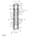
- einen Vertikalschnitt des Türbandes entlang der Linie A-A von
Fig. 3 und - Fig. 5
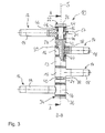
- eine perspektivische Explosionsdarstellung des Türbandes.
- Im Folgenden wird anhand der Darstellungen in den
Fig. 1 bis 5 ein Türband 10 näher erläutert. - Das Türband 10 weist mehrere Flügelteile 12, mehrere Rahmenteile 14, eine Verstelleinrichtung 20, eine zwischen den beiden Rahmenteilen 14 angeordnete Abstandshülse 13 und Lagermittel 44 auf.
- Bei der hier dargestellten Ausführung sind zwei Flügelteile 12 und zwei Rahmenteile 14 vorgesehen.
- Die Flügelteile 12 haben jeweils einen Tragzapfenabschnitt 18, der mit einem Außengewinde zum Eindrehen in ein Bohrloch eines nicht näher gezeigten Türflügels versehen ist. Ferner weisen die Flügelteile 12 jeweils einen Lagerabschnitt 16, der näherungsweise eine hohlzylindrische Grundform hat, auf. Des Weiteren ist in den Lagerabschnitt 16 eine Feststelleinrichtung 17 eingebracht. Die Feststelleinrichtung 17 weist eine Madenschraube 21 auf, die in eine in dem Lagerabschnitt 16 eingebrachte Öffnung 19 eingeschraubt wird.
- Die Rahmenteile 14 weisen ebenfalls jeweils einen Tragzapfenabschnitt 18 und einen näherungsweise hohlzylindrisch ausgebildeten Lagerabschnitt 16 auf. Die Rahmenteile 14 werden über ein Gewinde der Tragzapfenabschnitte 18 in eine Bohrung eines nicht dargestellten Rahmens, wie beispielsweise einer Zarge, eingeschraubt. Die Lagerabschnitte 16 der Rahmenteile 14 sind mit einem Innengewinde 15 versehen.
- Die Verstelleinrichtung 20 weist einen Drehstift 22 und zwei Drehelemente 24 auf.
- Der Drehstift 22 ist in mehrere Abschnitte aufgeteilt. An einer ersten Seite weist der Drehstift 22 einen Rückhalteabschnitt 26 auf, der im vorliegenden Ausführungsbeispiel als Kragen ausgebildet ist. In dem Rückhalteabschnitt 26 ist eine Werkzeugeingriffseinrichtung 27 in Form eines Innensechskant ausgebildet. An den Rückhalteabschnitt 26 schließt sich ein erster Lagerabschnitt 28 an, der im Querschnitt kreisförmig ausgebildet ist. An den ersten Lagerabschnitt 28 grenzt ein Eingriffsabschnitt 30 an, der vorliegend im Querschnitt eine viereckige Grundform aufweist. An den Eingriffsabschnitt 30 schließt sich ein zweiter Lagerabschnitt 32 an, der ebenfalls wie der erste Lagerabschnitt 28 im Querschnitt kreisförmig ausgebildet ist. In den zweiten Lagerabschnitt 32 ist endseitig eine Sicherungselementeingriffseinrichtung 34 zur Aufnahme eines Sicherungselements 36 eingebracht. Die Sicherungselementeingriffseinrichtung 34 ist im vorliegenden Fall als eine mit einem Innengewinde versehene Bohrung ausgebildet.
- Die Drehelemente 24 weisen einen zylindrischen Abschnitt 38, der mit einem Außengewinde 40 versehen ist, und einen Kragenabschnitt 42 auf.
- Des Weiteren sind zwischen dem Drehstift 22 und den Lagerabschnitten 16 der Flügelteile 12 sowie zwischen dem Drehstift 22 und der Abstandshülse 13 Lagermittel 44 eingebracht. Die Lagermittel 44 haben einen zylindrischen Abschnitt 46 und einen Kragenabschnitt 48.
- Nachfolgend wird die Anordnung der einzelnen Bestandteile des Türbandes 10 zueinander anhand der
Fig. 3 bis 5 näher erläutert. - Die Flügelteile 12 sind schwenkbar um eine Schwenkachse (S) mittels ihrer Lagerabschnitte 16 an dem ersten Lagerabschnitt 28 und dem zweiten Lagerabschnitt 32 des Drehstiftes 22 angeordnet. Zwischen den Lagerabschnitten 28 und 32 sowie den Lagerabschnitten 16 der Flügelteile 12 sind jeweils stirnseitig zwei Lagermittel 44 derart eingesetzt, dass der Kragenabschnitt 48 an den Stirnseiten des Lagerabschnitts 16 zur Auflage kommen und der zylindrische Abschnitt 46 zwischen dem Lagerabschnitt 16 der Flügelteile 12 und den Lagerabschnitten 28, 32 des Drehstiftes 22 angeordnet ist. Die beiden Rahmenteile 14 sind am Eingriffsabschnitt 30 des Drehstiftes 22 zwischen den beiden Flügelteilen 12 angeordnet. In das Innengewinde 15 der Lagerabschnitte 16 der Rahmenteile 14 sind die Drehelemente 24 über ihre Außengewinde 40 eingedreht. Der Eingriffsabschnitt 30 steht formschlüssig in Eingriff mit den Drehelementen 24. Die Kragenabschnitte 42 der Drehelemente 24 stützen sich jeweils an den Lagerabschnitten 16 der Flügelteile 12, insbesondere an den Kragenabschnitten 48 der Lagermittel 44, die in die Lagerabschnitte 16 der Flügelteile 12 eingebracht sind, ab. Zwischen den beiden Rahmenteilen 14 ist die Abstandshülse 13 angeordnet, wobei zwischen dem Drehstift 22 und der Abstandshülse 13 ebenfalls Lagermittel 44 derart eingebracht sind, dass die Kragenabschnitte 48 jeweils stirnseitig an der Abstandshülse 13 anliegen und der zylindrische Abschnitt 46 in die Abstandshülse 13 hineinragt. Zur Sicherung des Drehstiftes 22 wird das Sicherungselement 36 in die Bohrung der Sicherungselementeingriffseinrichtung 34 eingeschraubt.
- Mittels der Feststelleinrichtung 17, indem die Madenschraube 21 in die Öffnung 19 der Lagerabschnitte 16 eingeschraubt wird, werden die Flügelteile 12 gegen eine vertikale Verschiebung in Richtung der Schwenkachse (S) gesichert.
- Im Nachfolgenden wird eine mögliche Vorgehensweise zum Zusammenbau des Türbandes 10 erläutert.
- Zuerst werden die Flügelteile 12 sowie die Rahmenteile 14 mittels ihrer Tragzapfenabschnitte 18 in dafür vorgesehene Bohrungen eines nicht dargestellten Rahmens bzw. eines nicht dargestellten Türflügels eingebracht. Anschließend werden die Lagermittel 44 in die Lagerabschnitte 16 der Flügelteile 12 jeweils stirnseitig eingesetzt. Ebenfalls wird jeweils ein Lagermittel 16 jeweils stirnseitig in die Abstandshülse 13 eingebracht. Danach wird die mit den Lagermitteln 44 versehene Abstandshülse 13 zwischen den Lagerabschnitten 16 der Rahmenteile 14 angeordnet. Anschließend werden die Drehelemente 24 in die Lagerabschnitte 16 der Rahmenteile 14 eingeschraubt. Zum Fixieren der Flügelteile 12 an den Rahmenteilen 14 werden zunächst die vertikalen Achsen der Lagerabschnitte 16 der Flügelteile 12 und der Rahmenteile 14 derart zueinander ausgerichtet, dass die vertikalen Achsen eine Linie bilden. Anschließend wird der Drehstift 22 in der in
Fig. 5 gezeigten Einschubrichtung E in die Lagerabschnitte 16 eingeschoben. Abschließend wird das Sicherungselement 36 in die Sicherungselementeingriffseinrichtung 34 eingeschraubt und die Flügelteile 12 werden durch Feststellen der Feststelleinrichtung 17 an dem Drehstift 22 festgesetzt. - Nachfolgend wird eine mögliche Vorgehensweise zur vertikalen Verstellung des Türbandes 10 erläutert.
- Durch Drehen des Drehstiftes 22 erfolgt eine vertikale Einstellung eines nicht dargestellten Türflügels relativ zu einem nicht dargestellten Rahmen. Hierzu wird ein nicht näher dargestelltes Werkzeuges in die Werkzeugeingriffseinrichtung 27 eingesetzt, um so den Drehstift 22 zu drehen. Da der Drehstift 22 formschlüssig in Eingriff mit den Drehelementen 24 steht, werden die Drehelemente 24 ebenfalls mitgedreht. Die Drehelemente 24 befinden sich im Gewindeeingriff mit den Lagerabschnitten 16 der Rahmenteile 14, so dass sich die Drehelemente 24 je nach Drehrichtung in vertikaler Richtung nach oben oder unten entlang des Gewindeganges bewegen. Indem sich die Lagerabschnitte 16 der Flügelteile 12 an den Kragenabschnitten 42 der Drehelemente 24 abstützen, werden die Flügelteile 12 vertikal entlang der Schwenkachse S verschoben. Je nach Drehrichtung des Drehstiftes 22 erfolgt eine Höhenverstellung nach oben oder unten. Nach Einstellung der Höhe werden die Flügelteile 12 mittels der Feststelleinrichtung 17 festgesetzt.
- Bezugszeichenliste:
- 10
- Türband
- 12
- Flügelteil
- 13
- Abstandshülse
- 14
- Rahmenteil
- 15
- Innengewinde
- 16
- Lagerabschnitt
- 17
- Feststelleinrichtung
- 18
- Tragzapfenabschnitt
- 19
- Öffnung
- 20
- Verstelleinrichtung
- 21
- Madenschraube
- 22
- Drehstift
- 24
- Drehelemente
- 26
- Rückhalteabschnitt
- 27
- Werkzeugeingriffseinrichtung
- 28
- erster Lagerabschnitt
- 30
- Eingriffsabschnitt
- 32
- zweiter Lagerabschnitt
- 34
- Sicherungselementeingriffseinrichtung
- 36
- Sicherungselement
- 38
- zylindrischer Abschnitt
- 40
- Außengewinde
- 42
- Kragenabschnitt
- 44
- Lagermittel
- 46
- zylindrischer Abschnitt
- 48
- Kragenabschnitt
- S
- Schwenkachse
- E
- Einschubrichtung
Claims (10)
- Türband (10) in Form eines Einbohrbandes zum um eine Schwenkachse (S) schwenkbaren Lagern eines Türflügels an einem Rahmen oder dergleichen mit:wenigstens zwei Rahmenteilen (14) und wenigstens zwei Flügelteilen (12), die je einen Lagerabschnitt (16) und einen Tragzapfenabschnitt (18), der in dem Rahmen oder dem Türflügel befestigbar ist, aufweisen,und einer Verstelleinrichtung (20) zum relativen axialen Verstellen der Flügelteile (12) in Richtung der Schwenkachse (S), wobei die Verstelleinrichtung (20) einen Drehstift (22) und wenigstens zwei mit einem ersten Gewinde (40) versehene Drehelemente (24) aufweist,wobei wenigstens zwei der Lagerabschnitte (16) mit einem zweiten Gewinde (15) versehen sind,wobei das erste Gewinde (40) jeweils in Gewindeeingriff mit wenigstens einem der zweiten Gewinde (15) steht,und wobei sich der Drehstift (22) in die Lagerabschnitte (16) hinein erstreckt und formschlüssig mit den Drehelementen (24) in Eingriff steht, so dass durch Drehen des Drehstifts (22) über den Gewindeeingriff die Flügelteile (12) in Richtung der Schwenkachse (S) verschoben werden.
- Türband (10) nach Anspruch 1, dadurch gekennzeichnet, dass die Lagerabschnitte (16) der Rahmenteile (14) mit dem zweiten Gewinde (15) versehen sind.
- Türband (10) nach Anspruch 1 oder 2, dadurch gekennzeichnet, dass die Rahmenteile (14) zwischen den Flügelteilen (12) angeordnet sind.
- Türband (10) nach Anspruch 3, dadurch gekennzeichnet, dass zwischen den Rahmenteilen (14) eine Abstandshülse (13) angeordnet ist.
- Türband (10) nach einem der voranstehenden Ansprüche, dadurch gekennzeichnet, dass zwischen den Lagerabschnitten (16) der Flügelteile (12) und dem Drehstift (22) Lagermittel (44) eingebracht sind.
- Türband (10) nach Anspruch 3 oder 4, dadurch gekennzeichnet, dass zwischen der Abstandshülse (13) und dem Drehstift (22) Lagermittel (44) eingebracht sind.
- Türband (10) nach einem der voranstehenden Ansprüche, dadurch gekennzeichnet, dass der Drehstift (22) einen ersten Lagerabschnitt (28), einen zweiten Lagerabschnitt (32), einen Eingriffsabschnitt (30) und einen an dem ersten Lagerabschnitt (28) angeordneten Rückhalteabschnitt (26) aufweist.
- Türband (10) nach Anspruch 7, dadurch gekennzeichnet, dass der Drehstift (22) im Bereich des zweiten Lagerabschnitts (32) eine Sicherungselementeingriffseinrichtung (34) zum Eingriff eines Sicherungselements (36) aufweist.
- Türband (10) nach einem der voranstehenden Ansprüche, dadurch gekennzeichnet, dass der Drehstift (22) eine Werkzeugeingriffseinrichtung (27) zum Eingriff eines Werkzeuges aufweist über die der Drehstift (22) verdrehbar ist.
- Tür mit einem Türflügel und einem Türrahmen und wenigstens einem Türband (10) nach einem der voranstehenden Ansprüche.
Priority Applications (1)
| Application Number | Priority Date | Filing Date | Title |
|---|---|---|---|
| PL11181026T PL2434079T3 (pl) | 2010-09-28 | 2011-09-13 | Zawias wkręcany z regulacją w kierunku wysokości, do drzwi prawych i lewych |
Applications Claiming Priority (1)
| Application Number | Priority Date | Filing Date | Title |
|---|---|---|---|
| DE201010046741 DE102010046741B3 (de) | 2010-09-28 | 2010-09-28 | Türband in Form eines Einbohrbandes sowie eine damit versehene Tür |
Publications (3)
| Publication Number | Publication Date |
|---|---|
| EP2434079A2 true EP2434079A2 (de) | 2012-03-28 |
| EP2434079A3 EP2434079A3 (de) | 2013-10-02 |
| EP2434079B1 EP2434079B1 (de) | 2016-11-02 |
Family
ID=44720631
Family Applications (1)
| Application Number | Title | Priority Date | Filing Date |
|---|---|---|---|
| EP11181026.3A Not-in-force EP2434079B1 (de) | 2010-09-28 | 2011-09-13 | Höhenverstellbares, rechts-/links-verwendbares Einbohrband |
Country Status (3)
| Country | Link |
|---|---|
| EP (1) | EP2434079B1 (de) |
| DE (1) | DE102010046741B3 (de) |
| PL (1) | PL2434079T3 (de) |
Citations (1)
| Publication number | Priority date | Publication date | Assignee | Title |
|---|---|---|---|---|
| EP1452679A2 (de) | 2003-02-28 | 2004-09-01 | OTLAV SpA | Scharnier für bewegliche Elemente oder Möbelflügel mit einer Vorrichtung zur Höhenverstellung |
Family Cites Families (3)
| Publication number | Priority date | Publication date | Assignee | Title |
|---|---|---|---|---|
| DE8318296U1 (de) * | 1983-06-24 | 1983-10-20 | ANUBA-Beschläge X.Heine & Sohn GmbH, 7741 Vöhrenbach | Verstellbares scharnierband |
| DE29921535U1 (de) * | 1999-12-08 | 2001-04-12 | Hahn Gmbh & Co Kg Dr | Band für Türen, Fenster o.dgl. |
| DE102008049740B4 (de) * | 2008-09-30 | 2016-08-04 | Eco Schulte Gmbh & Co. Kg | Höhenverstellbares Band |
-
2010
- 2010-09-28 DE DE201010046741 patent/DE102010046741B3/de not_active Expired - Fee Related
-
2011
- 2011-09-13 PL PL11181026T patent/PL2434079T3/pl unknown
- 2011-09-13 EP EP11181026.3A patent/EP2434079B1/de not_active Not-in-force
Patent Citations (1)
| Publication number | Priority date | Publication date | Assignee | Title |
|---|---|---|---|---|
| EP1452679A2 (de) | 2003-02-28 | 2004-09-01 | OTLAV SpA | Scharnier für bewegliche Elemente oder Möbelflügel mit einer Vorrichtung zur Höhenverstellung |
Also Published As
| Publication number | Publication date |
|---|---|
| EP2434079A3 (de) | 2013-10-02 |
| PL2434079T3 (pl) | 2017-04-28 |
| DE102010046741B3 (de) | 2012-02-23 |
| EP2434079B1 (de) | 2016-11-02 |
Similar Documents
| Publication | Publication Date | Title |
|---|---|---|
| EP0259618B1 (de) | Während und nach der Montage verstellbares Tür- und Fensterband | |
| EP2586944B1 (de) | Scharnier mit Verstellelementen und Verstellkrone für diese Verstellelemente | |
| DE102010062565B4 (de) | Winkelverstellbarer Handgriff für ein Handwerkzeug | |
| WO2016146218A1 (de) | Tür- oder fensterscharnier | |
| DE202014002813U1 (de) | Temporäre Wandstütze | |
| EP3543434B1 (de) | Drückerlagerung mit einem an dieser lösbar befestigten tür- oder fensterdrücker | |
| DE202014100397U1 (de) | Bewegliche Stützvorrichtung für Solarkollektoren | |
| DE102010047774B4 (de) | Türscharnier | |
| EP1243739A1 (de) | Punkthalter für Platten | |
| EP3150786A1 (de) | Gelenkverbindung | |
| DE102007022311B4 (de) | Höhenverstellbare Lagereinheit für einen Schiebeflügel | |
| DE102015012641B3 (de) | Gelenkverbindung | |
| EP2434079B1 (de) | Höhenverstellbares, rechts-/links-verwendbares Einbohrband | |
| EP2696018B1 (de) | Schwenkbare Führungsschere, Lagervorrichtung sowie Führungssystem für Parallel-Ausstellfenster | |
| EP2418344B1 (de) | Türflügelbandteil, Türbandvorrichtung sowie Verwendungen derselben | |
| DE9308668U1 (de) | Lagerteil eines Lagers für die wenigstens drehbare Lagerung eines Flügels, eines Fensters, einer Tür o.dgl. | |
| DE10355495A1 (de) | Zerlegbares Gerüst | |
| EP2740872B1 (de) | Zur verdeckten anordnung vorgesehenes ecklager | |
| DE10216478B4 (de) | Gelenkarm-Markise | |
| DE102019128249B3 (de) | Band zur schwenkbaren Verbindung eines Flügels mit einem Rahmen | |
| DE20210361U1 (de) | Laufwagen für Schiebe- oder Kipp-Schiebe-Fenster oder -Türen | |
| EP3022374A1 (de) | Drehtorknickarmantriebsgestänge sowie drehtorknickarmantrieb und drehtor mit demselben | |
| EP3278693B1 (de) | Beschlag für eine schiebetüre | |
| DE102015117625A1 (de) | Einrichtung zur Realisierung einer Verschwenkkraftkomponente | |
| DE102006022184A1 (de) | Führungs- und Drehlager für eine Klapp-/Schiebeverglasung |
Legal Events
| Date | Code | Title | Description |
|---|---|---|---|
| PUAI | Public reference made under article 153(3) epc to a published international application that has entered the european phase |
Free format text: ORIGINAL CODE: 0009012 |
|
| AK | Designated contracting states |
Kind code of ref document: A2 Designated state(s): AL AT BE BG CH CY CZ DE DK EE ES FI FR GB GR HR HU IE IS IT LI LT LU LV MC MK MT NL NO PL PT RO RS SE SI SK SM TR |
|
| AX | Request for extension of the european patent |
Extension state: BA ME |
|
| PUAL | Search report despatched |
Free format text: ORIGINAL CODE: 0009013 |
|
| AK | Designated contracting states |
Kind code of ref document: A3 Designated state(s): AL AT BE BG CH CY CZ DE DK EE ES FI FR GB GR HR HU IE IS IT LI LT LU LV MC MK MT NL NO PL PT RO RS SE SI SK SM TR |
|
| AX | Request for extension of the european patent |
Extension state: BA ME |
|
| RIC1 | Information provided on ipc code assigned before grant |
Ipc: E05D 7/00 20060101ALI20130828BHEP Ipc: E05D 5/10 20060101ALN20130828BHEP Ipc: E05D 3/02 20060101AFI20130828BHEP Ipc: E05D 5/14 20060101ALN20130828BHEP Ipc: E05D 7/04 20060101ALI20130828BHEP Ipc: E05D 5/02 20060101ALN20130828BHEP |
|
| 17P | Request for examination filed |
Effective date: 20140221 |
|
| RBV | Designated contracting states (corrected) |
Designated state(s): AL AT BE BG CH CY CZ DE DK EE ES FI FR GB GR HR HU IE IS IT LI LT LU LV MC MK MT NL NO PL PT RO RS SE SI SK SM TR |
|
| RIC1 | Information provided on ipc code assigned before grant |
Ipc: E05D 5/10 20060101ALN20160330BHEP Ipc: E05D 7/04 20060101ALI20160330BHEP Ipc: E05D 5/14 20060101ALN20160330BHEP Ipc: E05D 3/02 20060101AFI20160330BHEP Ipc: E05D 7/00 20060101ALI20160330BHEP Ipc: E05D 5/02 20060101ALN20160330BHEP |
|
| GRAP | Despatch of communication of intention to grant a patent |
Free format text: ORIGINAL CODE: EPIDOSNIGR1 |
|
| INTG | Intention to grant announced |
Effective date: 20160509 |
|
| GRAS | Grant fee paid |
Free format text: ORIGINAL CODE: EPIDOSNIGR3 |
|
| GRAA | (expected) grant |
Free format text: ORIGINAL CODE: 0009210 |
|
| AK | Designated contracting states |
Kind code of ref document: B1 Designated state(s): AL AT BE BG CH CY CZ DE DK EE ES FI FR GB GR HR HU IE IS IT LI LT LU LV MC MK MT NL NO PL PT RO RS SE SI SK SM TR |
|
| REG | Reference to a national code |
Ref country code: GB Ref legal event code: FG4D Free format text: NOT ENGLISH |
|
| REG | Reference to a national code |
Ref country code: AT Ref legal event code: REF Ref document number: 842037 Country of ref document: AT Kind code of ref document: T Effective date: 20161115 Ref country code: CH Ref legal event code: EP |
|
| REG | Reference to a national code |
Ref country code: IE Ref legal event code: FG4D Free format text: LANGUAGE OF EP DOCUMENT: GERMAN |
|
| REG | Reference to a national code |
Ref country code: DE Ref legal event code: R096 Ref document number: 502011011036 Country of ref document: DE |
|
| PG25 | Lapsed in a contracting state [announced via postgrant information from national office to epo] |
Ref country code: LV Free format text: LAPSE BECAUSE OF FAILURE TO SUBMIT A TRANSLATION OF THE DESCRIPTION OR TO PAY THE FEE WITHIN THE PRESCRIBED TIME-LIMIT Effective date: 20161102 |
|
| REG | Reference to a national code |
Ref country code: NL Ref legal event code: MP Effective date: 20161102 |
|
| REG | Reference to a national code |
Ref country code: LT Ref legal event code: MG4D |
|
| PG25 | Lapsed in a contracting state [announced via postgrant information from national office to epo] |
Ref country code: SE Free format text: LAPSE BECAUSE OF FAILURE TO SUBMIT A TRANSLATION OF THE DESCRIPTION OR TO PAY THE FEE WITHIN THE PRESCRIBED TIME-LIMIT Effective date: 20161102 Ref country code: GR Free format text: LAPSE BECAUSE OF FAILURE TO SUBMIT A TRANSLATION OF THE DESCRIPTION OR TO PAY THE FEE WITHIN THE PRESCRIBED TIME-LIMIT Effective date: 20170203 Ref country code: NL Free format text: LAPSE BECAUSE OF FAILURE TO SUBMIT A TRANSLATION OF THE DESCRIPTION OR TO PAY THE FEE WITHIN THE PRESCRIBED TIME-LIMIT Effective date: 20161102 Ref country code: NO Free format text: LAPSE BECAUSE OF FAILURE TO SUBMIT A TRANSLATION OF THE DESCRIPTION OR TO PAY THE FEE WITHIN THE PRESCRIBED TIME-LIMIT Effective date: 20170202 Ref country code: LT Free format text: LAPSE BECAUSE OF FAILURE TO SUBMIT A TRANSLATION OF THE DESCRIPTION OR TO PAY THE FEE WITHIN THE PRESCRIBED TIME-LIMIT Effective date: 20161102 |
|
| PG25 | Lapsed in a contracting state [announced via postgrant information from national office to epo] |
Ref country code: RS Free format text: LAPSE BECAUSE OF FAILURE TO SUBMIT A TRANSLATION OF THE DESCRIPTION OR TO PAY THE FEE WITHIN THE PRESCRIBED TIME-LIMIT Effective date: 20161102 Ref country code: PT Free format text: LAPSE BECAUSE OF FAILURE TO SUBMIT A TRANSLATION OF THE DESCRIPTION OR TO PAY THE FEE WITHIN THE PRESCRIBED TIME-LIMIT Effective date: 20170302 Ref country code: FI Free format text: LAPSE BECAUSE OF FAILURE TO SUBMIT A TRANSLATION OF THE DESCRIPTION OR TO PAY THE FEE WITHIN THE PRESCRIBED TIME-LIMIT Effective date: 20161102 Ref country code: ES Free format text: LAPSE BECAUSE OF FAILURE TO SUBMIT A TRANSLATION OF THE DESCRIPTION OR TO PAY THE FEE WITHIN THE PRESCRIBED TIME-LIMIT Effective date: 20161102 Ref country code: HR Free format text: LAPSE BECAUSE OF FAILURE TO SUBMIT A TRANSLATION OF THE DESCRIPTION OR TO PAY THE FEE WITHIN THE PRESCRIBED TIME-LIMIT Effective date: 20161102 Ref country code: IS Free format text: LAPSE BECAUSE OF FAILURE TO SUBMIT A TRANSLATION OF THE DESCRIPTION OR TO PAY THE FEE WITHIN THE PRESCRIBED TIME-LIMIT Effective date: 20170302 |
|
| PG25 | Lapsed in a contracting state [announced via postgrant information from national office to epo] |
Ref country code: SK Free format text: LAPSE BECAUSE OF FAILURE TO SUBMIT A TRANSLATION OF THE DESCRIPTION OR TO PAY THE FEE WITHIN THE PRESCRIBED TIME-LIMIT Effective date: 20161102 Ref country code: RO Free format text: LAPSE BECAUSE OF FAILURE TO SUBMIT A TRANSLATION OF THE DESCRIPTION OR TO PAY THE FEE WITHIN THE PRESCRIBED TIME-LIMIT Effective date: 20161102 Ref country code: CZ Free format text: LAPSE BECAUSE OF FAILURE TO SUBMIT A TRANSLATION OF THE DESCRIPTION OR TO PAY THE FEE WITHIN THE PRESCRIBED TIME-LIMIT Effective date: 20161102 Ref country code: EE Free format text: LAPSE BECAUSE OF FAILURE TO SUBMIT A TRANSLATION OF THE DESCRIPTION OR TO PAY THE FEE WITHIN THE PRESCRIBED TIME-LIMIT Effective date: 20161102 Ref country code: DK Free format text: LAPSE BECAUSE OF FAILURE TO SUBMIT A TRANSLATION OF THE DESCRIPTION OR TO PAY THE FEE WITHIN THE PRESCRIBED TIME-LIMIT Effective date: 20161102 |
|
| REG | Reference to a national code |
Ref country code: DE Ref legal event code: R097 Ref document number: 502011011036 Country of ref document: DE |
|
| PG25 | Lapsed in a contracting state [announced via postgrant information from national office to epo] |
Ref country code: SM Free format text: LAPSE BECAUSE OF FAILURE TO SUBMIT A TRANSLATION OF THE DESCRIPTION OR TO PAY THE FEE WITHIN THE PRESCRIBED TIME-LIMIT Effective date: 20161102 Ref country code: BG Free format text: LAPSE BECAUSE OF FAILURE TO SUBMIT A TRANSLATION OF THE DESCRIPTION OR TO PAY THE FEE WITHIN THE PRESCRIBED TIME-LIMIT Effective date: 20170202 |
|
| PLBE | No opposition filed within time limit |
Free format text: ORIGINAL CODE: 0009261 |
|
| STAA | Information on the status of an ep patent application or granted ep patent |
Free format text: STATUS: NO OPPOSITION FILED WITHIN TIME LIMIT |
|
| REG | Reference to a national code |
Ref country code: FR Ref legal event code: PLFP Year of fee payment: 7 |
|
| 26N | No opposition filed |
Effective date: 20170803 |
|
| PG25 | Lapsed in a contracting state [announced via postgrant information from national office to epo] |
Ref country code: SI Free format text: LAPSE BECAUSE OF FAILURE TO SUBMIT A TRANSLATION OF THE DESCRIPTION OR TO PAY THE FEE WITHIN THE PRESCRIBED TIME-LIMIT Effective date: 20161102 |
|
| REG | Reference to a national code |
Ref country code: CH Ref legal event code: PL |
|
| GBPC | Gb: european patent ceased through non-payment of renewal fee |
Effective date: 20170913 |
|
| PG25 | Lapsed in a contracting state [announced via postgrant information from national office to epo] |
Ref country code: MC Free format text: LAPSE BECAUSE OF FAILURE TO SUBMIT A TRANSLATION OF THE DESCRIPTION OR TO PAY THE FEE WITHIN THE PRESCRIBED TIME-LIMIT Effective date: 20161102 |
|
| REG | Reference to a national code |
Ref country code: IE Ref legal event code: MM4A |
|
| REG | Reference to a national code |
Ref country code: BE Ref legal event code: MM Effective date: 20170930 |
|
| PG25 | Lapsed in a contracting state [announced via postgrant information from national office to epo] |
Ref country code: LU Free format text: LAPSE BECAUSE OF NON-PAYMENT OF DUE FEES Effective date: 20170913 |
|
| PG25 | Lapsed in a contracting state [announced via postgrant information from national office to epo] |
Ref country code: GB Free format text: LAPSE BECAUSE OF NON-PAYMENT OF DUE FEES Effective date: 20170913 Ref country code: IE Free format text: LAPSE BECAUSE OF NON-PAYMENT OF DUE FEES Effective date: 20170913 Ref country code: LI Free format text: LAPSE BECAUSE OF NON-PAYMENT OF DUE FEES Effective date: 20170930 Ref country code: CH Free format text: LAPSE BECAUSE OF NON-PAYMENT OF DUE FEES Effective date: 20170930 |
|
| PG25 | Lapsed in a contracting state [announced via postgrant information from national office to epo] |
Ref country code: BE Free format text: LAPSE BECAUSE OF NON-PAYMENT OF DUE FEES Effective date: 20170930 |
|
| REG | Reference to a national code |
Ref country code: FR Ref legal event code: PLFP Year of fee payment: 8 |
|
| PG25 | Lapsed in a contracting state [announced via postgrant information from national office to epo] |
Ref country code: MT Free format text: LAPSE BECAUSE OF FAILURE TO SUBMIT A TRANSLATION OF THE DESCRIPTION OR TO PAY THE FEE WITHIN THE PRESCRIBED TIME-LIMIT Effective date: 20161102 |
|
| PG25 | Lapsed in a contracting state [announced via postgrant information from national office to epo] |
Ref country code: HU Free format text: LAPSE BECAUSE OF FAILURE TO SUBMIT A TRANSLATION OF THE DESCRIPTION OR TO PAY THE FEE WITHIN THE PRESCRIBED TIME-LIMIT; INVALID AB INITIO Effective date: 20110913 |
|
| PG25 | Lapsed in a contracting state [announced via postgrant information from national office to epo] |
Ref country code: CY Free format text: LAPSE BECAUSE OF NON-PAYMENT OF DUE FEES Effective date: 20161102 |
|
| PG25 | Lapsed in a contracting state [announced via postgrant information from national office to epo] |
Ref country code: MK Free format text: LAPSE BECAUSE OF FAILURE TO SUBMIT A TRANSLATION OF THE DESCRIPTION OR TO PAY THE FEE WITHIN THE PRESCRIBED TIME-LIMIT Effective date: 20161102 |
|
| PG25 | Lapsed in a contracting state [announced via postgrant information from national office to epo] |
Ref country code: TR Free format text: LAPSE BECAUSE OF FAILURE TO SUBMIT A TRANSLATION OF THE DESCRIPTION OR TO PAY THE FEE WITHIN THE PRESCRIBED TIME-LIMIT Effective date: 20161102 |
|
| PG25 | Lapsed in a contracting state [announced via postgrant information from national office to epo] |
Ref country code: AL Free format text: LAPSE BECAUSE OF FAILURE TO SUBMIT A TRANSLATION OF THE DESCRIPTION OR TO PAY THE FEE WITHIN THE PRESCRIBED TIME-LIMIT Effective date: 20161102 |
|
| PGFP | Annual fee paid to national office [announced via postgrant information from national office to epo] |
Ref country code: AT Payment date: 20220919 Year of fee payment: 12 |
|
| PGFP | Annual fee paid to national office [announced via postgrant information from national office to epo] |
Ref country code: PL Payment date: 20220902 Year of fee payment: 12 Ref country code: FR Payment date: 20220920 Year of fee payment: 12 |
|
| PGFP | Annual fee paid to national office [announced via postgrant information from national office to epo] |
Ref country code: IT Payment date: 20220930 Year of fee payment: 12 Ref country code: DE Payment date: 20221121 Year of fee payment: 12 |
|
| P01 | Opt-out of the competence of the unified patent court (upc) registered |
Effective date: 20230508 |
|
| REG | Reference to a national code |
Ref country code: DE Ref legal event code: R119 Ref document number: 502011011036 Country of ref document: DE |
|
| REG | Reference to a national code |
Ref country code: AT Ref legal event code: MM01 Ref document number: 842037 Country of ref document: AT Kind code of ref document: T Effective date: 20230913 |
|
| PG25 | Lapsed in a contracting state [announced via postgrant information from national office to epo] |
Ref country code: AT Free format text: LAPSE BECAUSE OF NON-PAYMENT OF DUE FEES Effective date: 20230913 |
|
| PG25 | Lapsed in a contracting state [announced via postgrant information from national office to epo] |
Ref country code: FR Free format text: LAPSE BECAUSE OF NON-PAYMENT OF DUE FEES Effective date: 20230930 Ref country code: DE Free format text: LAPSE BECAUSE OF NON-PAYMENT OF DUE FEES Effective date: 20240403 Ref country code: AT Free format text: LAPSE BECAUSE OF NON-PAYMENT OF DUE FEES Effective date: 20230913 |
|
| PG25 | Lapsed in a contracting state [announced via postgrant information from national office to epo] |
Ref country code: PL Free format text: LAPSE BECAUSE OF NON-PAYMENT OF DUE FEES Effective date: 20230913 |
|
| PG25 | Lapsed in a contracting state [announced via postgrant information from national office to epo] |
Ref country code: PL Free format text: LAPSE BECAUSE OF NON-PAYMENT OF DUE FEES Effective date: 20230913 |
|
| PG25 | Lapsed in a contracting state [announced via postgrant information from national office to epo] |
Ref country code: IT Free format text: LAPSE BECAUSE OF NON-PAYMENT OF DUE FEES Effective date: 20230913 |
|
| PG25 | Lapsed in a contracting state [announced via postgrant information from national office to epo] |
Ref country code: IT Free format text: LAPSE BECAUSE OF NON-PAYMENT OF DUE FEES Effective date: 20230913 |