EP2434086B1 - Taillant de fleuret et ensemble de forage pour perçage de roche à percussion - Google Patents
Taillant de fleuret et ensemble de forage pour perçage de roche à percussion Download PDFInfo
- Publication number
- EP2434086B1 EP2434086B1 EP10178387.6A EP10178387A EP2434086B1 EP 2434086 B1 EP2434086 B1 EP 2434086B1 EP 10178387 A EP10178387 A EP 10178387A EP 2434086 B1 EP2434086 B1 EP 2434086B1
- Authority
- EP
- European Patent Office
- Prior art keywords
- drill bit
- rock drill
- button
- hole
- buttons
- Prior art date
- Legal status (The legal status is an assumption and is not a legal conclusion. Google has not performed a legal analysis and makes no representation as to the accuracy of the status listed.)
- Not-in-force
Links
- 239000011435 rock Substances 0.000 title claims description 121
- 238000005553 drilling Methods 0.000 title claims description 48
- 239000000463 material Substances 0.000 claims description 11
- 238000011010 flushing procedure Methods 0.000 claims description 8
- 230000001419 dependent effect Effects 0.000 claims description 3
- 239000013013 elastic material Substances 0.000 claims description 2
- 230000000284 resting effect Effects 0.000 claims description 2
- 230000035515 penetration Effects 0.000 description 10
- 238000005520 cutting process Methods 0.000 description 6
- 230000000712 assembly Effects 0.000 description 3
- 238000000429 assembly Methods 0.000 description 3
- 229910000831 Steel Inorganic materials 0.000 description 2
- 238000010276 construction Methods 0.000 description 2
- 230000000694 effects Effects 0.000 description 2
- 238000009527 percussion Methods 0.000 description 2
- 230000002035 prolonged effect Effects 0.000 description 2
- 239000010959 steel Substances 0.000 description 2
- UONOETXJSWQNOL-UHFFFAOYSA-N tungsten carbide Chemical compound [W+]#[C-] UONOETXJSWQNOL-UHFFFAOYSA-N 0.000 description 2
- 230000014509 gene expression Effects 0.000 description 1
- 238000012986 modification Methods 0.000 description 1
- 230000004048 modification Effects 0.000 description 1
- XLYOFNOQVPJJNP-UHFFFAOYSA-N water Substances O XLYOFNOQVPJJNP-UHFFFAOYSA-N 0.000 description 1
- 238000003466 welding Methods 0.000 description 1
Images



Classifications
-
- E—FIXED CONSTRUCTIONS
- E21—EARTH OR ROCK DRILLING; MINING
- E21B—EARTH OR ROCK DRILLING; OBTAINING OIL, GAS, WATER, SOLUBLE OR MELTABLE MATERIALS OR A SLURRY OF MINERALS FROM WELLS
- E21B10/00—Drill bits
- E21B10/36—Percussion drill bits
Definitions
- the present invention relates to a rock drill bit for percussive drilling comprising a bit head configured to be attached at an end of a drill element of a drilling assembly and having a diameter larger than that of said drill element, said bit head having at a front end as seen in the intended drilling direction a plurality of buttons distributed over said bit head and configured to engage material to be crushed, as well as a drilling assembly for percussive rock drilling according to the preamble of the independent claim therefor.
- the invention is not restricted to any type of drilling assembly for use of a said rock drill bit, but the former may be a down-the-hole hammer drill just as well as a top hammer drill, although the rock drill bit shown is especially intended for the latter type.
- said rock drill bit may have any conceivable size and has normally a diameter of 30 mm - 300 mm.
- the same absence of limitations applies to the intended percussion frequency and rotational speed of the rock drill bit in operation, although it may be mentioned that these are typically within the ranges 20 Hz - 100 Hz and 20 - 500 revolutions per minute, respectively, but the invention does not exclude the use of the rock drill bit in high frequency assemblies operating at a frequency above 250 Hz and which may reach more than 1 kHz.
- the drill bit has a bit head 2 configured to be attached at an end of a drill element, for example in the form of a drill tube or drill rod, of a drilling assembly and having a diameter larger than that of a said drill element.
- a drill element for example in the form of a drill tube or drill rod, of a drilling assembly and having a diameter larger than that of a said drill element.
- This drill element is not shown in these figures but may be intended to be received in a so-called skirt 3 integral with a bit head and having a smaller diameter than the bit head.
- the bit head has at a front end 4 as seen in the intended drilling direction a plurality of gauge buttons 5 distributed along the circumference of the bit button head 2.
- the gauge buttons are configured to engage material to be crushed and to determine the diameter of a hole 6 (see Fig 1 ) to be drilled by the rock drill bit.
- These gauge buttons are made of hard material, such as cemented carbide or tungsten carbide.
- Front buttons 7 also of hard material are arranged on a front surface 8 for engaging material to be crushed. It is also indicated how a flush channel opens at the front by a flushing hole 9 in the front surface.
- the gauge buttons 5 will engage and break rock close to the walls of a hole 6 in which the rock drill bit with said rod is located and the front buttons 7 will break rock closer to the centre of such a hole by impacts carried out by the rock drill bit in the direction of the arrow A.
- the drill bit will rotate somewhat, typically about 5°, between each such impact.
- the operation efficiency of a rock drill bit of this type is of course an important feature and this may be expressed as the penetration rate of the rock drill bit defined as the length of a hole drilled per time unit (meter/minute).
- the penetration rate of known rock drill bits of this type is dependent upon the wear of said buttons, especially the gauge buttons. It is indicated in Fig 2 that during the operation of such a rock drill bit material is abraded at the periphery of the gauge buttons resulting in a flat surface 10 there, which makes them less sharp and reduces the penetration rate. These flat surfaces 10 will during the operation of the rock drill bit grow and finally result in a diameter of a hole drilled determined by said gauge buttons being so much reduced that the rock drill bit has to be replaced. It is of course an ongoing attempt to increase the penetration rate and prolong the life time of a rock drill bit of the type defined in the introduction.
- a rock drill bit of the type just described is known through closest prior art document US 6 105 693 A .
- US 7 762 359 B1 discloses drill bits having rotatable cutting elements.
- said plurality of buttons includes gauge buttons distributed along the circumference of said bit head and configured to determine the diameter of a hole to be drilled by the rock drill bit, and at least one of said gauge buttons is allowed to rotate about its own symmetry axis.
- this gauge button will thanks to said self-sharpening effect maintain its contribution to the penetration rate of the rock drill bit until this gauge button has been worn so much that the diameter of a said hole drilled determined thereby has reached a minimum acceptable level.
- this will take longer than would said at least one gauge button be fixed with respect to the bit head, so that the lifetime of the rock drill bit may also be prolonged.
- the object of the present invention is to provide a rock drill bit of the type defined in the introduction being improved in at least some aspect with respect to such rock drill bits already known.
- This object is according to the invention obtained by providing such a rock drill bit in which at least one of said buttons is allowed to rotate about its own symmetry axis.
- this button By rotatably fitting at least one said button in the bit head this button will while carrying out percussive drilling be influenced by the impacts thereof and rotation of the rock drill bit to rotate about its own symmetry axis, so that the parts of said button engaging rock will vary and the button will be evenly worn and by that self-sharpened. This does not only result in a longer operating life of the drill bit, but through the self-sharpening effect the penetration rate of the rock drill bit may be maintained at a high level longer than would the button in question be fixed.
- the rock drill bit comprises a first member having a substantially circumferential ring surface defining a substantially frusto-conical shape as seen in the intended drilling direction, and said at least one gauge button has a base portion resting on said ring surface configured to transfer impact forces to the gauge button and to allow said base portion to move thereon when rotating. Transfer of impact forces to the gauge button by such a surface acting on said base portion of said at least one gauge button may increase the efficiency of the impacts and reduce stresses on said gauge button.
- the rock drill bit comprises a second member defining said front end of said bit head and having said plurality of gauge buttons extending out thereof, and said at least one gauge button allowed to rotate is arranged in a hole in said second member and allowed to move with respect to walls defining said hole when rotating.
- said at least one gauge button allowed to rotate has a base portion with a larger cross-section than the rest of the gauge button, and at least a part of said hole in said second member has a cross-sectional area being smaller than that of said base portion so as to maintain the gauge button received in said second member.
- said hole is a through-hole
- said gauge button is arranged with the base portion thereof on a rear side of said hole as seen in the intended drilling direction.
- said first member has means configured to secure this member to a said drill element.
- This means that the rock drill bit may be secured to a drill element through said first member providing said ring surface for transfer of impact forces to said at least one gauge button.
- the rock drill bit has both a said first and second member and comprises means configured to secure said second member to said first member, which means that said ring surface will be located inside the bit head behind said second member.
- Said means configured to secure said second member to said first member is according to another embodiment of the invention configured to releasably secure these members to each other, which means that a second member with gauge buttons may be removed and replaced when the diameter determined by the gauge buttons has reached the minimum limit while keeping said first member, so that not the entire rock drill bit has to be replaced resulting in saving of costs.
- said first member is a ring configured to be supported on and/or secured to an end of said drill element.
- a so-called pusher ring is of particular interest and results in a simple construction of the rock drill bit if the rock drill bit also comprises means for securing said second member and by that said rock drill bit to a said drill element.
- the first member has neither to be secured to a drill element nor to said second member, but it will be kept in place by said second member.
- a majority of said gauge buttons are allowed to rotate about their own symmetry axis, and according to a further embodiment of the invention all said gauge buttons of the rock drill bit are allowed to rotate about their own symmetry axis.
- the advantages of arranging gauge buttons so as to be allowed to rotate will be the greater the more of the gauge buttons that are so arranged resulting in a said prolonged life time of the rock drill bit and a high penetration rate maintained over a longer time.
- said bit head has a front surface provided with a plurality of front buttons configured to engage material to be crushed.
- These front buttons may be fixed with respect to said front surface, but according to another embodiment of the invention at least one of said front buttons is allowed to rotate about its own symmetry axis, which will result in an even wear of said front button and by that a self-sharpening action thereof, so that it will carry out its task more efficiently and over a longer time than would it be fixed with respect to said front surface of the bit head.
- said at least one front button has a design similar to that of said at least one gauge button, and said second member is configured to receive said at least one front button similarly to said at least one gauge button.
- a majority of said front buttons or all said front buttons are allowed to rotate about their own symmetry axes.
- the rock drill bit comprises a flush channel extending through said bit head and having at least one flushing hole opening at said front end and passing the circumference of at least one said button allowed to rotate about its own symmetry axis.
- said at least one button allowed to rotate is arranged in a hole in said bit head and allowed to move with respect to walls defining said hole when rotating, said at least one button is provided with a circumferential annular groove, said walls defining said hole have a female member, and the rock drill bit comprises means configured to engage said groove and said female member so as to lock said button in said hole while allowing it to rotate.
- said female member is an annular groove in said hole walls
- said engaging means comprises a ring of elastic material. This allows easy mounting of said button in said hole by pushing it thereinto while compressing said ring, which will when arriving to said annular groove in said hole walls expand and lock the button in place while allowing it to freely rotate.
- said engaging means comprises a pin configured to be pushed into said groove and said female member for being fixed with respect to said bit head and lock said button in said hole while allowing it to rotate.
- a lock pin will also by simple means provide a reliable locking of said button in said hole of the bit head while allowing it to freely rotate.
- the invention also relates to a drilling assembly for percussive rock drilling according to the appended independent claim for such an assembly.
- a drilling assembly makes it possible to carry out rock drilling with a high penetration rate over a longer time and while replacing the rock drill bit thereof more seldom with respect to such drilling assemblies utilizing known rock drill bits.
- the invention also relates to a use of a rock drill bit according to the invention for percussive rock drilling into earth material, such as rock.
- Fig 3 shows very schematically the principle of a rock drill bit according to the present invention, in which all gauge buttons 20 and all front buttons 21 are allowed to rotate about their own symmetry axis by being received in holes 22 in a substantially circumferential ring surface 23 defining a substantially frusto-conical shape as seen in the intended drilling direction and in a front surface 24, respectively.
- the buttons are preferably of tungsten carbide.
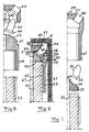
- the rock drill bit 30 comprises a first member 31 having a substantially circumferential ring surface 32 defining a substantially frusto-conical shape as seen in the intended drilling direction.
- This first member 31 is provided with means configured to secure this member to a drill element 33, in which this securing means is formed by a sleeve-like portion 34 of the first member 31 provided with engagement means in the form of an internal thread 35 configured to engage engagement means in the form of an external thread 36 on the drill element.
- the rock drill bit further comprises a second member 37 defining a front end 38 of a bit head 39 of the rock drill bit.
- This second member is provided with a plurality of through holes 40 receiving the gauge buttons 41 and front buttons 42 while allowing these to rotate about their own symmetry axis.
- the through-holes 40 each have a diameter slightly exceeding (suitably by a diameter difference in the order of 30-80 ⁇ m) the diameter of the respective button received therein for allowing the button to move with respect to walls 43 in the second member 37 defining said hole when rotating.
- This difference in diameter has been exaggerated in this figure and also in the embodiment shown in Fig 6 and described below for better illustrating this feature.
- the gauge buttons as well as the front buttons are provided with a base portion 44 with larger cross-section than the rest of the button and also than the respective hole 40 so as to maintain the button received in the second member.
- a gauge button 41 rests by the base portion 44 thereof on said ring surface 32 configured to transfer impact forces to the gauge button and allow the base portion to move thereon when rotating. This means that impact forces are transferred to the gauge buttons from a surface 32 located inside the drill bit.
- the first member has also surfaces 45 directed in an intended drilling direction for supporting base portions of front buttons and transferring impact forces thereto while allowing these base portions to move on these surfaces 45 when rotating.
- the bit head 39 will through a shoulder 47 on the first member 31 provide a clearance C with respect to this member 31, so that the button 41 may rotate freely without jamming. Particular measures are taken for flushing the surfaces and spaces surrounding the button, which will be explained more in detail below.
- the rock drill bit comprises means 46 configured to secure the second member 37 to the first member 31.
- the securing means is preferably configured to releasably secure these members to each other, for instance by mutually securing them by engagement of threads. This would then mean that it would be possible to remove said second member with buttons for replacement while keeping the first member after the buttons have been that much worn that they have to be replaced. Welding or press fitting are other possible alternatives of said securing means 46 easier to accomplish.
- buttons thereof When carrying out percussive drilling with the rock drill bit shown in Fig 4 and 5 as illustrated in Fig 4 the buttons thereof will be allowed to rotate about their own axes, which means that the gauge buttons 41 will be worn evenly and maintain their sharpness, so that a high penetration rate may be maintained over a long period of time and the diameter of the hole defined by the gauge buttons will be reduced more slowly than would the gauge buttons be fixedly arranged in the bit head.
- Figs. 6 and 7 illustrate a rock drill bit 50 according to a second embodiment of the invention.
- This rock drill bit has a first member 51 in the form of a ring configured to be supported on and/or secured to an end 52 of a drill element 53 and having a ring surface 54 forming a support for a base portion 55 of each gauge button 56 in the same way as the corresponding surface 32 in the embodiment shown in Figs. 4 and 5 .
- impact forces will through this surface be transferred to the gauge buttons while the base portions thereof are allowed to move thereon when rotating.
- a second member 57 of the rock drill bit has through holes 58 receiving said gauge buttons and allowing them to move with respect to walls of these holes when rotating.
- the front buttons 59 are, as an example, in this embodiment fixedly secured to a front end 60 of the second member 57.
- the second member 57 is in this embodiment provided with means for securing this member to a drill element 53 by having a sleeve-like portion 61 designed to receive a drill element and having engagement means in the form of an internal thread 62 for engaging with engagement means in the form of an external thread 63 on the drill element for releasably securing said second member to the drill element and by that also keeping said ring 51, a so-called pusher ring, in place.
- the first member 51 is provided with a collar 64, so that the first 51 and second 57 members are fixed with respect to each other while leaving a clearance 66 therebetween for the button to freely rotate. Proper flushing of a button allowed to rotate is also important.
- the rock drill bit has a conventional flush channel 67 extending through the bit head.
- the flush channel has also at least one flushing hole 68 (see the arrows F indicating the flow of flushing medium) opening at the first end 60 and passing the clearance 66 and the circumference of the button 56 allowed to rotate. This will keep said clearance 66 clear and eliminates wear problems while the button rotates inside the hole 58.
- the function of this embodiment of the invention in operation appears clearly from the above discussion of inter alia the first embodiment of the present invention.
- FIG 8 A part of a rock drill bit according to a third embodiment of the invention is very schematically shown in Fig 8 .
- This rock drill bit is provided with alternative means to lock a button 80 to a drill bit head 81 while allowing the button to rotate.
- a dead hole 82 in the bit head designed to receive the button 80 is provided with an annular groove 83, and the button 80 is provided with a corresponding annular groove 84 receiving an elastic lock ring 85, for example a ring, such as a C-ring, made from steel.
- an elastic lock ring 85 for example a ring, such as a C-ring, made from steel.
- Fig 9 illustrates an alternative way of locking a button 90 to a bit head not shown in a rock drill bit according to a fourth embodiment of the invention while allowing the button to rotate.
- This is achieved by providing the button 90 with an annular groove 91 as in the embodiment shown in Fig 8 .
- a lock pin 92 is used instead of a lock ring, and this lock pin is after pushing the button 90 into a corresponding hole in the bit head pushed into the groove 91 while locking the button in place and still allowing it to rotate about its own symmetry axis.
- Fig 10 illustrates very schematically a drilling assembly for percussive rock drilling according to the present invention having a rock drill bit 70 according to an embodiment of the invention provided with gauge buttons 71.
- This drilling assembly is a so-called top hammer drill acting upon the rock drill bit from a location above the ground and has power means 72, such as diesel engine and hydraulic pump, configured to drive the rock drill 76, which in turn makes said drill element 73 and the rock drill bit to rotate and carry out percussions and by that crush the rock.
- power means 72 such as diesel engine and hydraulic pump
- the drilling assembly has also means 74, such as a compressed air generator, configured to flush cuttings resulted from engagement of the gauge buttons and the front buttons of the drill bit away from the region occupied by the drill bit.
- the drilling assembly has a control arrangement 75 configured to control the operation of the power means 72 so as to adapt the frequency of impacts and the rotational speed of the drill bit. It has turned out that drill bits according to the present invention with buttons allowed to rotate about their own symmetry axis are particularly well suited to be used in drilling assemblies controlled to have frequencies above 250 Hz, preferably above 350 Hz and most preferred in the range of 350 Hz - 1000 Hz.
- Drilling with a drilling assembly according to Fig 8 with a rock drill bit according to the present invention will be more efficient than with rock drill bits already known, since the penetration rate may be kept at a high level longer and the stops needed for replacing the rock drill bit or parts thereof will be less frequently occurring.
- buttons of the rock drill bit may differ a lot with respect to the embodiments shown in the figures.
- substantially used in the expressions “substantially a frusto-conical shape” and “substantially circumferential ring” also cover the case when cutting recesses or grooves and/or gauge buttons intersect the ring, as shown in the figures.
Landscapes
- Engineering & Computer Science (AREA)
- Life Sciences & Earth Sciences (AREA)
- Geology (AREA)
- Mining & Mineral Resources (AREA)
- Mechanical Engineering (AREA)
- Physics & Mathematics (AREA)
- Environmental & Geological Engineering (AREA)
- Fluid Mechanics (AREA)
- General Life Sciences & Earth Sciences (AREA)
- Geochemistry & Mineralogy (AREA)
- Earth Drilling (AREA)
- Processing Of Stones Or Stones Resemblance Materials (AREA)
Claims (24)
- Taillant de fleuret (30, 50) pour forage à percussion comprenant une tête de taillant (39) configurée pour être attachée à une extrémité d'un élément de forage (33, 53) d'un ensemble de forage et ayant un diamètre supérieur à celui dudit élément de taillant, ladite tête de taillant ayant, à une extrémité avant (38, 60) en vue dans la direction de forage prévue, une pluralité de boutons (41, 42, 56, 59, 80, 90) répartis sur ladite tête de taillant et configurés pour se mettre en prise avec le matériau à broyer, caractérisé en ce qu'au moins l'un desdits boutons (41, 42, 56, 80, 90) est autorisé à tourner autour de son propre axe de symétrie et en ce qu'une portion de base de l'au moins un bouton rotatif repose directement contre un fond d'un trou (40, 58, 82) dans l'extrémité avant (38, 60) pour transférer des forces d'impact au bouton et tout en laissant la portion de base se déplacer sur celui-ci en tournant.
- Taillant de fleuret selon la revendication 1, caractérisé en ce que ladite pluralité de boutons comprend des boutons de calibre (41, 56, 80, 90) répartis le long de la circonférence de ladite tête de taillant (39, 81) et configurés pour déterminer le diamètre d'un trou à forer par le taillant de fleuret, et en ce qu'au moins l'un desdits boutons de calibre (41, 56, 80, 90) est autorisé à tourner autour de son propre axe de symétrie.
- Taillant de fleuret selon la revendication 2, caractérisé en ce qu'il comprend un premier organe (31, 51) comportant une surface d'anneau sensiblement circonférentielle (32, 54) définissant une forme sensiblement tronconique en vue dans la direction de forage prévue, et en ce que ledit au moins un bouton de calibre (41, 56) comporte une portion de base (44, 55) reposant sur ladite surface d'anneau configurée pour transférer des forces d'impact au bouton de calibre et pour permettre à ladite portion de base de se déplacer sur celle-ci en tournant.
- Taillant de fleuret selon la revendication 2 ou 3, caractérisé en ce qu'il comprend un deuxième organe (37, 57) définissant ladite extrémité avant (38, 60) dudit taillant de fleuret et ayant ladite pluralité de boutons de calibre (41, 56) s'étendant hors de celui-ci, et en ce que ledit au moins un bouton de calibre autorisé à tourner est agencé dans un trou (40, 58) dans ledit deuxième organe et est autorisé à se déplacer par rapport à des parois définissant ledit trou en tournant.
- Taillant de fleuret selon la revendication 4, caractérisé en ce que ledit au moins un bouton de calibre (41, 56) autorisé à tourner comporte une portion de base (44, 55) avec une coupe transversale supérieure au reste du bouton de calibre, et en ce qu'au moins une partie dudit trou (40, 58) dans ledit deuxième organe (37, 57) a une surface de coupe transversale inférieure à celle de ladite portion de base de manière à maintenir le bouton de calibre reçu dans ledit deuxième organe.
- Taillant de fleuret selon la revendication 5, caractérisé en ce que ledit trou (40, 58) est un trou traversant, et en ce que ledit bouton de calibre (41, 56) est agencé avec la portion de base (44, 55) de celui-ci sur un côté arrière dudit trou en vue dans la direction de forage prévue.
- Taillant de fleuret selon la revendication 3 ou selon l'une quelconque des revendications 4 à 6 dépendant de la revendication 3, caractérisé en ce que ledit premier organe (31) comporte un moyen (34, 35) configuré pour fixer cet organe un dit élément de forage (33).
- Taillant de fleuret selon les revendications 4 et 7, caractérisé en ce qu'il comprend un moyen (46) configuré pour fixer ledit deuxième organe (37) au dit premier organe (31).
- Taillant de fleuret selon la revendication 8, caractérisé en ce que ledit moyen (46) configuré pour fixer ledit deuxième organe (37) au dit premier organe (31) est configuré pour fixer de manière amovible ces organes l'un à l'autre.
- Taillant de fleuret selon la revendication 3 ou selon l'une quelconque des revendications 4 à 6 dépendant de la revendication 3, caractérisé en ce que ledit premier organe est un anneau (51) configuré pour être supporté sur une extrémité (52) dudit un élément de forage (53) et/ou fixé à celle-ci.
- Taillant de fleuret selon l'une quelconque des revendications 4 à 6 et selon la revendication 10, caractérisé en ce qu'il comprend un moyen (61, 62) pour fixer ledit deuxième organe (57) et par cela ledit taillant de fleuret au dit un élément de forage (53).
- Taillant de fleuret selon l'une quelconque des revendications 2 à 11, caractérisé en ce qu'une majorité desdits boutons de calibre (41, 56, 80, 90) sont autorisés à tourner autour de leur propre axe de symétrie.
- Taillant de fleuret selon l'une quelconque des revendications 2 à 12, caractérisé en ce que tous lesdits boutons de calibre (41, 56, 80, 90) du taillant de fleuret sont autorisés à tourner autour de leur propre axe de symétrie.
- Taillant de fleuret selon l'une quelconque des revendications précédentes, caractérisé en ce que ladite tête de taillant comporte une surface avant pourvue d'une pluralité de boutons avant (42, 59) configurés pour se mettre en prise avec le matériau à broyer.
- Taillant de fleuret selon la revendication 14, caractérisé en ce qu'au moins l'un (42) desdits boutons avant est autorisé à tourner autour de son propre axe de symétrie.
- Taillant de fleuret selon l'une quelconque des revendications 4 à 6 et selon la revendication 15, caractérisé en ce que ledit au moins un bouton avant (42) est d'une conception similaire à celle dudit au moins un bouton de calibre (41), et en ce que ledit deuxième organe (37) est configuré pour recevoir ledit au moins un bouton avant similairement au dit au moins un bouton de calibre.
- Taillant de fleuret selon la revendication 15 ou 16, caractérisé en ce qu'une majorité desdits boutons avant (42) ou tous lesdits boutons avant sont autorisés à tourner autour de leur propre axe de symétrie.
- Taillant de fleuret selon l'une quelconque des revendications précédentes, caractérisé en ce qu'il comprend un canal de lavage (67) s'étendant à travers ladite tête de taillant (39) et comportant au moins un trou de lavage (68) s'ouvrant à ladite extrémité avant et passant la circonférence d'au moins un dit bouton (56) autorisé à tourner autour de son propre axe de symétrie.
- Taillant de fleuret selon l'une quelconque des revendications 1, 2, 12 à 15, 17 et 18, caractérisé en ce que ledit au moins un bouton autorisé à tourner est agencé dans un trou (82) dans ladite tête de taillant (81) et est autorisé à se déplacer par rapport à des parois définissant ledit trou en tournant, en ce que ledit au moins un bouton est pourvu d'une rainure annulaire circonférentielle (84, 91), en ce que lesdites parois définissant ledit trou comportent un organe femelle (83) et en ce que ledit taillant de fleuret comprend un moyen (85, 92) configuré pour se mettre en prise avec ladite rainure (84) et ledit organe femelle (83) de manière à verrouiller ledit bouton dans ledit trou tout en l'autorisant à tourner.
- Taillant de fleuret selon la revendication 19, caractérisé en ce que ledit organe femelle est une rainure annulaire (84) dans lesdites parois de trou, et en ce que ledit moyen de mise en prise comprend un anneau (85) en matériau élastique.
- Taillant de fleuret selon la revendication 19, caractérisé en ce que ledit moyen de mise en prise comprend une broche (92) configurée pour être poussée dans ladite rainure (91) et ledit organe femelle pour être fixée par rapport à ladite tête de taillant et verrouiller ledit bouton (90) dans ledit trou tout en lui permettant de tourner.
- Ensemble de forage pour perçage de roche à percussion comprenant un taillant de fleuret (70), un moyen moteur (72) configuré pour agir sur ledit taillant de fleuret pour le faire tourner et effectuer des impacts pour se mettre en prise avec le matériau à broyer, et un agencement de commande (75) configuré pour commander le fonctionnement dudit moyen moteur, caractérisé en ce que ledit taillant de fleuret est un taillant de fleuret selon l'une quelconque des revendications 1 à 21.
- Ensemble de forage selon la revendication 22, caractérisé en ce que l'agencement de commande (75) est configuré pour commander ledit moyen moteur (72) afin d'obtenir une fréquence desdits impacts dépassant 250 Hz, dépassant 350 Hz ou étant dans la plage de 350 Hz à 1000 Hz.
- Utilisation d'un taillant de fleuret (30, 50) selon l'une quelconque des revendications 1 à 21, pour un forage à percussion dans la terre, comme da la roche.
Priority Applications (20)
| Application Number | Priority Date | Filing Date | Title |
|---|---|---|---|
| EP10178387.6A EP2434086B1 (fr) | 2010-09-22 | 2010-09-22 | Taillant de fleuret et ensemble de forage pour perçage de roche à percussion |
| PCT/EP2011/066114 WO2012038342A1 (fr) | 2010-09-22 | 2011-09-16 | Trépan de forage de roche et ensemble de forage pour forage de roche à percussion |
| US13/825,416 US20130180784A1 (en) | 2010-09-22 | 2011-09-16 | Rock drill bit and a drilling assembly for percussive rock drilling |
| RU2013118265/03A RU2574646C2 (ru) | 2010-09-22 | 2011-09-16 | Буровое долото для горной породы и бурильная компоновка для ударного бурения горной породы |
| BR112013006621A BR112013006621A2 (pt) | 2010-09-22 | 2011-09-16 | uma broca de rocha e um conjunto de perfuração para perfuração de rocha por percussão |
| KR1020137010145A KR20140005880A (ko) | 2010-09-22 | 2011-09-16 | 충격식 착암용 착암 드릴 비트 및 드릴링 조립체 |
| AU2011304461A AU2011304461B2 (en) | 2010-09-22 | 2011-09-16 | A rock drill bit and a drilling assembly for percussive rock drilling |
| CN2011800460419A CN103261561A (zh) | 2010-09-22 | 2011-09-16 | 用于冲击式岩石钻凿的凿岩钻头和钻凿组件 |
| CA2811674A CA2811674A1 (fr) | 2010-09-22 | 2011-09-16 | Trepan de forage de roche et ensemble de forage pour forage de roche a percussion |
| CN2011800460438A CN103339339A (zh) | 2010-09-22 | 2011-09-20 | 冲击式钻进用的凿岩钻头以及凿岩钻头球齿 |
| EP11757880.7A EP2619396A1 (fr) | 2010-09-22 | 2011-09-20 | Trépan de forage de roche pour forage à percussion et bouton de trépan de forage de roche |
| RU2013118269/03A RU2571783C2 (ru) | 2010-09-22 | 2011-09-20 | Буровое долото для горной породы для ударного бурения и вставной штырь бурового долота |
| CA2812600A CA2812600A1 (fr) | 2010-09-22 | 2011-09-20 | Trepan de forage de roche pour forage a percussion et bouton de trepan de forage de roche |
| KR1020137010147A KR20140009149A (ko) | 2010-09-22 | 2011-09-20 | 충격식 드릴링용 착암 드릴 비트 및 착암 드릴 비트 버튼 |
| BR112013006623A BR112013006623A2 (pt) | 2010-09-22 | 2011-09-20 | uma broca de rocha para perfuração por percussão e um botão de broca de rocha |
| PCT/EP2011/066323 WO2012038428A1 (fr) | 2010-09-22 | 2011-09-20 | Trépan de forage de roche pour forage à percussion et bouton de trépan de forage de roche |
| AU2011304382A AU2011304382B2 (en) | 2010-09-22 | 2011-09-20 | A rock drill bit for percussive drilling and a rock drill bit button |
| US13/825,533 US20130180785A1 (en) | 2010-09-22 | 2011-09-20 | Rock drill bit for percussive drilling and a rock drill bit button |
| ZA2013/02143A ZA201302143B (en) | 2010-09-22 | 2013-03-20 | A rock drill bit and a drilling assembly for percussive rock drilling |
| AU2015238819A AU2015238819A1 (en) | 2010-09-22 | 2015-10-07 | A rock drill bit and a drilling assembly for percussive rock drilling |
Applications Claiming Priority (1)
| Application Number | Priority Date | Filing Date | Title |
|---|---|---|---|
| EP10178387.6A EP2434086B1 (fr) | 2010-09-22 | 2010-09-22 | Taillant de fleuret et ensemble de forage pour perçage de roche à percussion |
Publications (2)
| Publication Number | Publication Date |
|---|---|
| EP2434086A1 EP2434086A1 (fr) | 2012-03-28 |
| EP2434086B1 true EP2434086B1 (fr) | 2013-05-15 |
Family
ID=43500325
Family Applications (2)
| Application Number | Title | Priority Date | Filing Date |
|---|---|---|---|
| EP10178387.6A Not-in-force EP2434086B1 (fr) | 2010-09-22 | 2010-09-22 | Taillant de fleuret et ensemble de forage pour perçage de roche à percussion |
| EP11757880.7A Withdrawn EP2619396A1 (fr) | 2010-09-22 | 2011-09-20 | Trépan de forage de roche pour forage à percussion et bouton de trépan de forage de roche |
Family Applications After (1)
| Application Number | Title | Priority Date | Filing Date |
|---|---|---|---|
| EP11757880.7A Withdrawn EP2619396A1 (fr) | 2010-09-22 | 2011-09-20 | Trépan de forage de roche pour forage à percussion et bouton de trépan de forage de roche |
Country Status (10)
| Country | Link |
|---|---|
| US (2) | US20130180784A1 (fr) |
| EP (2) | EP2434086B1 (fr) |
| KR (2) | KR20140005880A (fr) |
| CN (2) | CN103261561A (fr) |
| AU (3) | AU2011304461B2 (fr) |
| BR (2) | BR112013006621A2 (fr) |
| CA (2) | CA2811674A1 (fr) |
| RU (1) | RU2571783C2 (fr) |
| WO (2) | WO2012038342A1 (fr) |
| ZA (1) | ZA201302143B (fr) |
Families Citing this family (20)
| Publication number | Priority date | Publication date | Assignee | Title |
|---|---|---|---|---|
| EP2586960B1 (fr) * | 2011-10-27 | 2016-01-13 | Sandvik Intellectual Property AB | Trépan doté d'un bouton enfoncé et outil de perçage de roche à utiliser avec un tel trépan |
| US9759014B2 (en) | 2013-05-13 | 2017-09-12 | Baker Hughes Incorporated | Earth-boring tools including movable formation-engaging structures and related methods |
| EP2921639A1 (fr) | 2014-03-18 | 2015-09-23 | Sandvik Intellectual Property AB | Trépan à percussion avec de multiples ensembles d'inserts de coupe avant |
| US9476257B2 (en) | 2014-05-07 | 2016-10-25 | Baker Hughes Incorporated | Formation-engaging assemblies and earth-boring tools including such assemblies |
| US9359826B2 (en) | 2014-05-07 | 2016-06-07 | Baker Hughes Incorporated | Formation-engaging structures having retention features, earth-boring tools including such structures, and related methods |
| US10502001B2 (en) | 2014-05-07 | 2019-12-10 | Baker Hughes, A Ge Company, Llc | Earth-boring tools carrying formation-engaging structures |
| US10494871B2 (en) | 2014-10-16 | 2019-12-03 | Baker Hughes, A Ge Company, Llc | Modeling and simulation of drill strings with adaptive systems |
| US10895001B2 (en) * | 2015-03-26 | 2021-01-19 | Sandvik Intellectual Property Ab | Rock drill button |
| US10273759B2 (en) | 2015-12-17 | 2019-04-30 | Baker Hughes Incorporated | Self-adjusting earth-boring tools and related systems and methods |
| US10280479B2 (en) | 2016-01-20 | 2019-05-07 | Baker Hughes, A Ge Company, Llc | Earth-boring tools and methods for forming earth-boring tools using shape memory materials |
| US10508323B2 (en) | 2016-01-20 | 2019-12-17 | Baker Hughes, A Ge Company, Llc | Method and apparatus for securing bodies using shape memory materials |
| US10487589B2 (en) | 2016-01-20 | 2019-11-26 | Baker Hughes, A Ge Company, Llc | Earth-boring tools, depth-of-cut limiters, and methods of forming or servicing a wellbore |
| US10633929B2 (en) | 2017-07-28 | 2020-04-28 | Baker Hughes, A Ge Company, Llc | Self-adjusting earth-boring tools and related systems |
| GB201800250D0 (en) * | 2018-01-08 | 2018-02-21 | Element Six Gmbh | Drill bit with wearshield |
| ES2963144T3 (es) * | 2019-02-15 | 2024-03-25 | Sandvik Mining And Construction Tools Ab | Inserto para una pata de muñón de una herramienta de perforación giratoria |
| CN112211566A (zh) * | 2020-10-30 | 2021-01-12 | 中国建筑第四工程局有限公司 | 一种用以掘进大粒径中等风化核的人工挖孔桩成孔方法 |
| USD1044894S1 (en) * | 2022-07-09 | 2024-10-01 | Zhejiang Pulanka Rock Tools Co., Ltd. | Button drill bit |
| USD1046584S1 (en) * | 2022-09-16 | 2024-10-15 | Boart Longyear Company | Drill bit |
| USD1068887S1 (en) * | 2023-01-12 | 2025-04-01 | Boart Longyear Manufacturing And Distribution Inc. | Drill bit |
| CN119914177A (zh) | 2023-10-30 | 2025-05-02 | 肯纳金属印度有限公司 | 钻土工具 |
Family Cites Families (15)
| Publication number | Priority date | Publication date | Assignee | Title |
|---|---|---|---|---|
| US4073354A (en) * | 1976-11-26 | 1978-02-14 | Christensen, Inc. | Earth-boring drill bits |
| CA1194857A (fr) * | 1982-02-20 | 1985-10-08 | Nl Industries, Inc. | Trepans de forage |
| EP0178387B1 (fr) * | 1984-10-19 | 1992-10-07 | BBC Brown Boveri AG | Dispositif semi-conducteur de puissance à blocage par gâchette |
| NO870356L (no) * | 1986-02-03 | 1987-08-04 | Boart Int Ltd | Borkrone. |
| US4751972A (en) * | 1986-03-13 | 1988-06-21 | Smith International, Inc. | Revolving cutters for rock bits |
| US4690228A (en) * | 1986-03-14 | 1987-09-01 | Eastman Christensen Company | Changeover bit for extended life, varied formations and steady wear |
| SE508490C2 (sv) * | 1996-03-14 | 1998-10-12 | Sandvik Ab | Bergborrkrona för slående borrning |
| US6105693A (en) * | 1999-02-18 | 2000-08-22 | Sandvik Ab | Partially enhanced percussive drill bit |
| CN2413013Y (zh) * | 2000-03-01 | 2001-01-03 | 蔡友梅 | 螺纹圈分体潜孔钻头 |
| US7472764B2 (en) * | 2005-03-25 | 2009-01-06 | Baker Hughes Incorporated | Rotary drill bit shank, rotary drill bits so equipped, and methods of manufacture |
| FI123572B (fi) * | 2005-10-07 | 2013-07-15 | Sandvik Mining & Constr Oy | Menetelmä ja kallionporauslaite reiän poraamiseksi kallioon |
| US7845436B2 (en) * | 2005-10-11 | 2010-12-07 | Us Synthetic Corporation | Cutting element apparatuses, drill bits including same, methods of cutting, and methods of rotating a cutting element |
| US7703559B2 (en) * | 2006-05-30 | 2010-04-27 | Smith International, Inc. | Rolling cutter |
| US7762359B1 (en) * | 2007-08-22 | 2010-07-27 | Us Synthetic Corporation | Cutter assembly including rotatable cutting element and drill bit using same |
| RU2387787C1 (ru) * | 2009-02-27 | 2010-04-27 | Николай Митрофанович Панин | Буровое шарошечное долото |
-
2010
- 2010-09-22 EP EP10178387.6A patent/EP2434086B1/fr not_active Not-in-force
-
2011
- 2011-09-16 CN CN2011800460419A patent/CN103261561A/zh active Pending
- 2011-09-16 WO PCT/EP2011/066114 patent/WO2012038342A1/fr not_active Ceased
- 2011-09-16 BR BR112013006621A patent/BR112013006621A2/pt not_active IP Right Cessation
- 2011-09-16 KR KR1020137010145A patent/KR20140005880A/ko not_active Withdrawn
- 2011-09-16 AU AU2011304461A patent/AU2011304461B2/en not_active Expired - Fee Related
- 2011-09-16 US US13/825,416 patent/US20130180784A1/en not_active Abandoned
- 2011-09-16 CA CA2811674A patent/CA2811674A1/fr not_active Abandoned
- 2011-09-20 KR KR1020137010147A patent/KR20140009149A/ko not_active Withdrawn
- 2011-09-20 BR BR112013006623A patent/BR112013006623A2/pt not_active IP Right Cessation
- 2011-09-20 AU AU2011304382A patent/AU2011304382B2/en not_active Ceased
- 2011-09-20 CA CA2812600A patent/CA2812600A1/fr not_active Abandoned
- 2011-09-20 EP EP11757880.7A patent/EP2619396A1/fr not_active Withdrawn
- 2011-09-20 CN CN2011800460438A patent/CN103339339A/zh active Pending
- 2011-09-20 US US13/825,533 patent/US20130180785A1/en not_active Abandoned
- 2011-09-20 RU RU2013118269/03A patent/RU2571783C2/ru not_active IP Right Cessation
- 2011-09-20 WO PCT/EP2011/066323 patent/WO2012038428A1/fr not_active Ceased
-
2013
- 2013-03-20 ZA ZA2013/02143A patent/ZA201302143B/en unknown
-
2015
- 2015-10-07 AU AU2015238819A patent/AU2015238819A1/en not_active Abandoned
Also Published As
| Publication number | Publication date |
|---|---|
| US20130180785A1 (en) | 2013-07-18 |
| AU2011304461B2 (en) | 2015-09-03 |
| CN103339339A (zh) | 2013-10-02 |
| RU2571783C2 (ru) | 2015-12-20 |
| BR112013006623A2 (pt) | 2016-06-28 |
| AU2011304461A1 (en) | 2013-04-11 |
| KR20140009149A (ko) | 2014-01-22 |
| RU2013118265A (ru) | 2014-10-27 |
| CA2811674A1 (fr) | 2012-03-29 |
| KR20140005880A (ko) | 2014-01-15 |
| AU2011304382A1 (en) | 2013-04-11 |
| AU2011304382B2 (en) | 2015-01-15 |
| EP2434086A1 (fr) | 2012-03-28 |
| CA2812600A1 (fr) | 2012-03-29 |
| RU2013118269A (ru) | 2014-10-27 |
| AU2015238819A1 (en) | 2015-10-29 |
| WO2012038342A1 (fr) | 2012-03-29 |
| ZA201302143B (en) | 2014-09-25 |
| CN103261561A (zh) | 2013-08-21 |
| EP2619396A1 (fr) | 2013-07-31 |
| US20130180784A1 (en) | 2013-07-18 |
| BR112013006621A2 (pt) | 2016-06-21 |
| WO2012038428A1 (fr) | 2012-03-29 |
Similar Documents
| Publication | Publication Date | Title |
|---|---|---|
| EP2434086B1 (fr) | Taillant de fleuret et ensemble de forage pour perçage de roche à percussion | |
| CA2526254C (fr) | Trepan, systeme et procede permettant de forer un trou de forage dans une formation terrestre | |
| US7461706B2 (en) | Drilling apparatus with percussive action cutter | |
| US9062504B2 (en) | Rock drill bit, a drilling assembly and a method for percussive rock drilling | |
| WO2012039630A1 (fr) | Trépan hybride | |
| US20200149349A1 (en) | Hybrid drill bit | |
| US7455126B2 (en) | Percussive drill bit, drilling system comprising such a drill bit and method of drilling a bore hole | |
| CN112696149A (zh) | 潜孔取芯锤头及环形潜孔锤 | |
| KR20120094714A (ko) | 지반 천공용 해머의 비트 | |
| CA2526249A1 (fr) | Trepan a percussion, systeme de forage comprenant ce trepan et procede de forage d'un trou de forage | |
| US6112835A (en) | Drilling apparatus having a radially displaceable reamer | |
| CN207513555U (zh) | 一种旋挖钻机的钻头 | |
| CN214659921U (zh) | 潜孔取芯锤头及环形潜孔锤 | |
| RU162327U1 (ru) | Долото буровое | |
| KR102273699B1 (ko) | 일자형 해머 비트가 구비된 지반 굴착용 에어 해머를 이용한 지반 굴착 방법 | |
| RU2470135C1 (ru) | Буровое долото | |
| RU2574646C2 (ru) | Буровое долото для горной породы и бурильная компоновка для ударного бурения горной породы | |
| JP2013527043A (ja) | 削岩機、着脱式カートリッジ、停止リング及びドリルリグ | |
| EP3433463B1 (fr) | Dispositif de forage de fond | |
| CN111425139A (zh) | 复合钻头 |
Legal Events
| Date | Code | Title | Description |
|---|---|---|---|
| PUAI | Public reference made under article 153(3) epc to a published international application that has entered the european phase |
Free format text: ORIGINAL CODE: 0009012 |
|
| 17P | Request for examination filed |
Effective date: 20100922 |
|
| AK | Designated contracting states |
Kind code of ref document: A1 Designated state(s): AL AT BE BG CH CY CZ DE DK EE ES FI FR GB GR HR HU IE IS IT LI LT LU LV MC MK MT NL NO PL PT RO SE SI SK SM TR |
|
| AX | Request for extension of the european patent |
Extension state: BA ME RS |
|
| GRAP | Despatch of communication of intention to grant a patent |
Free format text: ORIGINAL CODE: EPIDOSNIGR1 |
|
| GRAS | Grant fee paid |
Free format text: ORIGINAL CODE: EPIDOSNIGR3 |
|
| GRAA | (expected) grant |
Free format text: ORIGINAL CODE: 0009210 |
|
| AK | Designated contracting states |
Kind code of ref document: B1 Designated state(s): AL AT BE BG CH CY CZ DE DK EE ES FI FR GB GR HR HU IE IS IT LI LT LU LV MC MK MT NL NO PL PT RO SE SI SK SM TR |
|
| REG | Reference to a national code |
Ref country code: GB Ref legal event code: FG4D Ref country code: CH Ref legal event code: EP |
|
| REG | Reference to a national code |
Ref country code: AT Ref legal event code: REF Ref document number: 612254 Country of ref document: AT Kind code of ref document: T Effective date: 20130615 |
|
| REG | Reference to a national code |
Ref country code: IE Ref legal event code: FG4D |
|
| REG | Reference to a national code |
Ref country code: DE Ref legal event code: R096 Ref document number: 602010007060 Country of ref document: DE Effective date: 20130711 |
|
| REG | Reference to a national code |
Ref country code: SE Ref legal event code: TRGR |
|
| REG | Reference to a national code |
Ref country code: LT Ref legal event code: MG4D |
|
| REG | Reference to a national code |
Ref country code: NL Ref legal event code: VDEP Effective date: 20130515 |
|
| PG25 | Lapsed in a contracting state [announced via postgrant information from national office to epo] |
Ref country code: IS Free format text: LAPSE BECAUSE OF FAILURE TO SUBMIT A TRANSLATION OF THE DESCRIPTION OR TO PAY THE FEE WITHIN THE PRESCRIBED TIME-LIMIT Effective date: 20130915 Ref country code: LT Free format text: LAPSE BECAUSE OF FAILURE TO SUBMIT A TRANSLATION OF THE DESCRIPTION OR TO PAY THE FEE WITHIN THE PRESCRIBED TIME-LIMIT Effective date: 20130515 Ref country code: GR Free format text: LAPSE BECAUSE OF FAILURE TO SUBMIT A TRANSLATION OF THE DESCRIPTION OR TO PAY THE FEE WITHIN THE PRESCRIBED TIME-LIMIT Effective date: 20130816 Ref country code: SI Free format text: LAPSE BECAUSE OF FAILURE TO SUBMIT A TRANSLATION OF THE DESCRIPTION OR TO PAY THE FEE WITHIN THE PRESCRIBED TIME-LIMIT Effective date: 20130515 Ref country code: NO Free format text: LAPSE BECAUSE OF FAILURE TO SUBMIT A TRANSLATION OF THE DESCRIPTION OR TO PAY THE FEE WITHIN THE PRESCRIBED TIME-LIMIT Effective date: 20130815 Ref country code: ES Free format text: LAPSE BECAUSE OF FAILURE TO SUBMIT A TRANSLATION OF THE DESCRIPTION OR TO PAY THE FEE WITHIN THE PRESCRIBED TIME-LIMIT Effective date: 20130826 Ref country code: PT Free format text: LAPSE BECAUSE OF FAILURE TO SUBMIT A TRANSLATION OF THE DESCRIPTION OR TO PAY THE FEE WITHIN THE PRESCRIBED TIME-LIMIT Effective date: 20130916 |
|
| PG25 | Lapsed in a contracting state [announced via postgrant information from national office to epo] |
Ref country code: BG Free format text: LAPSE BECAUSE OF FAILURE TO SUBMIT A TRANSLATION OF THE DESCRIPTION OR TO PAY THE FEE WITHIN THE PRESCRIBED TIME-LIMIT Effective date: 20130815 Ref country code: PL Free format text: LAPSE BECAUSE OF FAILURE TO SUBMIT A TRANSLATION OF THE DESCRIPTION OR TO PAY THE FEE WITHIN THE PRESCRIBED TIME-LIMIT Effective date: 20130515 Ref country code: HR Free format text: LAPSE BECAUSE OF FAILURE TO SUBMIT A TRANSLATION OF THE DESCRIPTION OR TO PAY THE FEE WITHIN THE PRESCRIBED TIME-LIMIT Effective date: 20130515 |
|
| PG25 | Lapsed in a contracting state [announced via postgrant information from national office to epo] |
Ref country code: LV Free format text: LAPSE BECAUSE OF FAILURE TO SUBMIT A TRANSLATION OF THE DESCRIPTION OR TO PAY THE FEE WITHIN THE PRESCRIBED TIME-LIMIT Effective date: 20130515 |
|
| PG25 | Lapsed in a contracting state [announced via postgrant information from national office to epo] |
Ref country code: BE Free format text: LAPSE BECAUSE OF FAILURE TO SUBMIT A TRANSLATION OF THE DESCRIPTION OR TO PAY THE FEE WITHIN THE PRESCRIBED TIME-LIMIT Effective date: 20130515 Ref country code: DK Free format text: LAPSE BECAUSE OF FAILURE TO SUBMIT A TRANSLATION OF THE DESCRIPTION OR TO PAY THE FEE WITHIN THE PRESCRIBED TIME-LIMIT Effective date: 20130515 Ref country code: CZ Free format text: LAPSE BECAUSE OF FAILURE TO SUBMIT A TRANSLATION OF THE DESCRIPTION OR TO PAY THE FEE WITHIN THE PRESCRIBED TIME-LIMIT Effective date: 20130515 Ref country code: EE Free format text: LAPSE BECAUSE OF FAILURE TO SUBMIT A TRANSLATION OF THE DESCRIPTION OR TO PAY THE FEE WITHIN THE PRESCRIBED TIME-LIMIT Effective date: 20130515 Ref country code: SK Free format text: LAPSE BECAUSE OF FAILURE TO SUBMIT A TRANSLATION OF THE DESCRIPTION OR TO PAY THE FEE WITHIN THE PRESCRIBED TIME-LIMIT Effective date: 20130515 |
|
| PG25 | Lapsed in a contracting state [announced via postgrant information from national office to epo] |
Ref country code: IT Free format text: LAPSE BECAUSE OF FAILURE TO SUBMIT A TRANSLATION OF THE DESCRIPTION OR TO PAY THE FEE WITHIN THE PRESCRIBED TIME-LIMIT Effective date: 20130515 Ref country code: NL Free format text: LAPSE BECAUSE OF FAILURE TO SUBMIT A TRANSLATION OF THE DESCRIPTION OR TO PAY THE FEE WITHIN THE PRESCRIBED TIME-LIMIT Effective date: 20130515 Ref country code: RO Free format text: LAPSE BECAUSE OF FAILURE TO SUBMIT A TRANSLATION OF THE DESCRIPTION OR TO PAY THE FEE WITHIN THE PRESCRIBED TIME-LIMIT Effective date: 20130515 |
|
| PLBE | No opposition filed within time limit |
Free format text: ORIGINAL CODE: 0009261 |
|
| STAA | Information on the status of an ep patent application or granted ep patent |
Free format text: STATUS: NO OPPOSITION FILED WITHIN TIME LIMIT |
|
| 26N | No opposition filed |
Effective date: 20140218 |
|
| PG25 | Lapsed in a contracting state [announced via postgrant information from national office to epo] |
Ref country code: MC Free format text: LAPSE BECAUSE OF FAILURE TO SUBMIT A TRANSLATION OF THE DESCRIPTION OR TO PAY THE FEE WITHIN THE PRESCRIBED TIME-LIMIT Effective date: 20130515 |
|
| REG | Reference to a national code |
Ref country code: DE Ref legal event code: R097 Ref document number: 602010007060 Country of ref document: DE Effective date: 20140218 |
|
| REG | Reference to a national code |
Ref country code: FR Ref legal event code: ST Effective date: 20140530 |
|
| REG | Reference to a national code |
Ref country code: IE Ref legal event code: MM4A |
|
| PG25 | Lapsed in a contracting state [announced via postgrant information from national office to epo] |
Ref country code: IE Free format text: LAPSE BECAUSE OF NON-PAYMENT OF DUE FEES Effective date: 20130922 |
|
| PG25 | Lapsed in a contracting state [announced via postgrant information from national office to epo] |
Ref country code: FR Free format text: LAPSE BECAUSE OF NON-PAYMENT OF DUE FEES Effective date: 20130930 |
|
| REG | Reference to a national code |
Ref country code: CH Ref legal event code: PL |
|
| PG25 | Lapsed in a contracting state [announced via postgrant information from national office to epo] |
Ref country code: SM Free format text: LAPSE BECAUSE OF FAILURE TO SUBMIT A TRANSLATION OF THE DESCRIPTION OR TO PAY THE FEE WITHIN THE PRESCRIBED TIME-LIMIT Effective date: 20130515 |
|
| PG25 | Lapsed in a contracting state [announced via postgrant information from national office to epo] |
Ref country code: CY Free format text: LAPSE BECAUSE OF FAILURE TO SUBMIT A TRANSLATION OF THE DESCRIPTION OR TO PAY THE FEE WITHIN THE PRESCRIBED TIME-LIMIT Effective date: 20130515 Ref country code: TR Free format text: LAPSE BECAUSE OF FAILURE TO SUBMIT A TRANSLATION OF THE DESCRIPTION OR TO PAY THE FEE WITHIN THE PRESCRIBED TIME-LIMIT Effective date: 20130515 Ref country code: MT Free format text: LAPSE BECAUSE OF FAILURE TO SUBMIT A TRANSLATION OF THE DESCRIPTION OR TO PAY THE FEE WITHIN THE PRESCRIBED TIME-LIMIT Effective date: 20130515 |
|
| PG25 | Lapsed in a contracting state [announced via postgrant information from national office to epo] |
Ref country code: LU Free format text: LAPSE BECAUSE OF NON-PAYMENT OF DUE FEES Effective date: 20130922 Ref country code: LI Free format text: LAPSE BECAUSE OF NON-PAYMENT OF DUE FEES Effective date: 20140930 Ref country code: CH Free format text: LAPSE BECAUSE OF NON-PAYMENT OF DUE FEES Effective date: 20140930 Ref country code: MK Free format text: LAPSE BECAUSE OF FAILURE TO SUBMIT A TRANSLATION OF THE DESCRIPTION OR TO PAY THE FEE WITHIN THE PRESCRIBED TIME-LIMIT Effective date: 20130515 Ref country code: HU Free format text: LAPSE BECAUSE OF FAILURE TO SUBMIT A TRANSLATION OF THE DESCRIPTION OR TO PAY THE FEE WITHIN THE PRESCRIBED TIME-LIMIT; INVALID AB INITIO Effective date: 20100922 |
|
| PGFP | Annual fee paid to national office [announced via postgrant information from national office to epo] |
Ref country code: GB Payment date: 20150916 Year of fee payment: 6 Ref country code: FI Payment date: 20150909 Year of fee payment: 6 Ref country code: DE Payment date: 20150916 Year of fee payment: 6 |
|
| PGFP | Annual fee paid to national office [announced via postgrant information from national office to epo] |
Ref country code: AT Payment date: 20150825 Year of fee payment: 6 Ref country code: SE Payment date: 20150911 Year of fee payment: 6 |
|
| REG | Reference to a national code |
Ref country code: DE Ref legal event code: R119 Ref document number: 602010007060 Country of ref document: DE |
|
| PG25 | Lapsed in a contracting state [announced via postgrant information from national office to epo] |
Ref country code: FI Free format text: LAPSE BECAUSE OF NON-PAYMENT OF DUE FEES Effective date: 20160922 Ref country code: SE Free format text: LAPSE BECAUSE OF NON-PAYMENT OF DUE FEES Effective date: 20160923 |
|
| REG | Reference to a national code |
Ref country code: SE Ref legal event code: EUG |
|
| REG | Reference to a national code |
Ref country code: AT Ref legal event code: MM01 Ref document number: 612254 Country of ref document: AT Kind code of ref document: T Effective date: 20160922 |
|
| GBPC | Gb: european patent ceased through non-payment of renewal fee |
Effective date: 20160922 |
|
| PG25 | Lapsed in a contracting state [announced via postgrant information from national office to epo] |
Ref country code: DE Free format text: LAPSE BECAUSE OF NON-PAYMENT OF DUE FEES Effective date: 20170401 Ref country code: GB Free format text: LAPSE BECAUSE OF NON-PAYMENT OF DUE FEES Effective date: 20160922 |
|
| PG25 | Lapsed in a contracting state [announced via postgrant information from national office to epo] |
Ref country code: AT Free format text: LAPSE BECAUSE OF NON-PAYMENT OF DUE FEES Effective date: 20160922 |
|
| PG25 | Lapsed in a contracting state [announced via postgrant information from national office to epo] |
Ref country code: AL Free format text: LAPSE BECAUSE OF FAILURE TO SUBMIT A TRANSLATION OF THE DESCRIPTION OR TO PAY THE FEE WITHIN THE PRESCRIBED TIME-LIMIT Effective date: 20130515 |