EP2434094A2 - Leitschaufel für Dampfturbine und Dampfturbine - Google Patents
Leitschaufel für Dampfturbine und Dampfturbine Download PDFInfo
- Publication number
- EP2434094A2 EP2434094A2 EP11181062A EP11181062A EP2434094A2 EP 2434094 A2 EP2434094 A2 EP 2434094A2 EP 11181062 A EP11181062 A EP 11181062A EP 11181062 A EP11181062 A EP 11181062A EP 2434094 A2 EP2434094 A2 EP 2434094A2
- Authority
- EP
- European Patent Office
- Prior art keywords
- stator vane
- steam turbine
- curved line
- flow
- moving blade
- Prior art date
- Legal status (The legal status is an assumption and is not a legal conclusion. Google has not performed a legal analysis and makes no representation as to the accuracy of the status listed.)
- Withdrawn
Links
- 239000012530 fluid Substances 0.000 claims abstract description 52
- 238000011144 upstream manufacturing Methods 0.000 claims abstract description 17
- 230000035939 shock Effects 0.000 description 10
- 238000010586 diagram Methods 0.000 description 9
- 238000000034 method Methods 0.000 description 9
- 230000009467 reduction Effects 0.000 description 9
- 230000000694 effects Effects 0.000 description 6
- 239000011295 pitch Substances 0.000 description 4
- 230000008569 process Effects 0.000 description 2
- 230000008901 benefit Effects 0.000 description 1
- 230000015572 biosynthetic process Effects 0.000 description 1
- 230000008859 change Effects 0.000 description 1
- 239000000470 constituent Substances 0.000 description 1
- 230000006872 improvement Effects 0.000 description 1
- 230000004048 modification Effects 0.000 description 1
- 238000012986 modification Methods 0.000 description 1
- 230000007480 spreading Effects 0.000 description 1
- 230000001629 suppression Effects 0.000 description 1
Images


Classifications
-
- F—MECHANICAL ENGINEERING; LIGHTING; HEATING; WEAPONS; BLASTING
- F01—MACHINES OR ENGINES IN GENERAL; ENGINE PLANTS IN GENERAL; STEAM ENGINES
- F01D—NON-POSITIVE DISPLACEMENT MACHINES OR ENGINES, e.g. STEAM TURBINES
- F01D5/00—Blades; Blade-carrying members; Heating, heat-insulating, cooling or antivibration means on the blades or the members
- F01D5/12—Blades
- F01D5/14—Form or construction
- F01D5/141—Shape, i.e. outer, aerodynamic form
-
- F—MECHANICAL ENGINEERING; LIGHTING; HEATING; WEAPONS; BLASTING
- F05—INDEXING SCHEMES RELATING TO ENGINES OR PUMPS IN VARIOUS SUBCLASSES OF CLASSES F01-F04
- F05D—INDEXING SCHEME FOR ASPECTS RELATING TO NON-POSITIVE-DISPLACEMENT MACHINES OR ENGINES, GAS-TURBINES OR JET-PROPULSION PLANTS
- F05D2220/00—Application
- F05D2220/30—Application in turbines
- F05D2220/31—Application in turbines in steam turbines
-
- F—MECHANICAL ENGINEERING; LIGHTING; HEATING; WEAPONS; BLASTING
- F05—INDEXING SCHEMES RELATING TO ENGINES OR PUMPS IN VARIOUS SUBCLASSES OF CLASSES F01-F04
- F05D—INDEXING SCHEME FOR ASPECTS RELATING TO NON-POSITIVE-DISPLACEMENT MACHINES OR ENGINES, GAS-TURBINES OR JET-PROPULSION PLANTS
- F05D2240/00—Components
- F05D2240/10—Stators
- F05D2240/12—Fluid guiding means, e.g. vanes
- F05D2240/121—Fluid guiding means, e.g. vanes related to the leading edge of a stator vane
-
- F—MECHANICAL ENGINEERING; LIGHTING; HEATING; WEAPONS; BLASTING
- F05—INDEXING SCHEMES RELATING TO ENGINES OR PUMPS IN VARIOUS SUBCLASSES OF CLASSES F01-F04
- F05D—INDEXING SCHEME FOR ASPECTS RELATING TO NON-POSITIVE-DISPLACEMENT MACHINES OR ENGINES, GAS-TURBINES OR JET-PROPULSION PLANTS
- F05D2240/00—Components
- F05D2240/10—Stators
- F05D2240/12—Fluid guiding means, e.g. vanes
- F05D2240/122—Fluid guiding means, e.g. vanes related to the trailing edge of a stator vane
-
- F—MECHANICAL ENGINEERING; LIGHTING; HEATING; WEAPONS; BLASTING
- F05—INDEXING SCHEMES RELATING TO ENGINES OR PUMPS IN VARIOUS SUBCLASSES OF CLASSES F01-F04
- F05D—INDEXING SCHEME FOR ASPECTS RELATING TO NON-POSITIVE-DISPLACEMENT MACHINES OR ENGINES, GAS-TURBINES OR JET-PROPULSION PLANTS
- F05D2250/00—Geometry
- F05D2250/70—Shape
- F05D2250/71—Shape curved
- F05D2250/711—Shape curved convex
-
- F—MECHANICAL ENGINEERING; LIGHTING; HEATING; WEAPONS; BLASTING
- F05—INDEXING SCHEMES RELATING TO ENGINES OR PUMPS IN VARIOUS SUBCLASSES OF CLASSES F01-F04
- F05D—INDEXING SCHEME FOR ASPECTS RELATING TO NON-POSITIVE-DISPLACEMENT MACHINES OR ENGINES, GAS-TURBINES OR JET-PROPULSION PLANTS
- F05D2250/00—Geometry
- F05D2250/70—Shape
- F05D2250/71—Shape curved
- F05D2250/713—Shape curved inflexed
Definitions
- the present invention relates to a steam turbine stator vane.
- a steam turbine has a plurality of stages that are each constituted by stator vanes and moving blades, while the stages are arranged in the axial direction of a turbine rotor.
- An exhaust hood is installed on the downstream side of the steam turbine. Steam that is a working fluid is accelerated by stator vanes that serve as a convergent passage so that kinetic energy of the steam is increased. The kinetic energy is converted into rotational energy by moving blades so that power is generated.
- the first problem is a reduction in the efficiency due to a reduction in the degree of reaction.
- a spreading angle (flare angle) on the outer circumferential side of the turbine) of the turbine passage through which steam flows increases.
- a velocity component of steam in a radial direction (of the turbine) at a stator vane outlet increases.
- the velocity component in the radial direction is increased by centrifugal force of the moving blades.
- Intervals of an inner circumferential portion of a uniform flow diagram of a two-dimensional passage projected in a plane including a rotational axis increase.
- a substantial passage area that corresponds to the moving blade is larger than a substantial passage area that corresponds to the stator vane.
- the degree of reaction which is the ratio of a reduced amount of pressure at the moving blade to a reduced amount of pressure at the stage, is reduced.
- the optimal value of the degree of reaction to maximize the efficiency exists.
- the turbine blades are designed on the basis of the degree of reaction at which the efficiency becomes maximum. Thus, when the degree of reaction is reduced, the efficiency is reduced.
- JP-H10-131707-A discloses a technique for setting the degree of reaction to an appropriate degree on the basis of a Bow angle ⁇ (that is a parameter of the shape of the tangential lean) and the ratio of a projecting amount on a tip side to a pitch on an inner circumferential side.
- European Patent Application No. 2075408 , U.S. Patent No. 6099248 , JP-2009- 121468-A and International Publication No. 2005/005784 each disclose a technique for adjusting the degree of reaction to an appropriate degree by means of a combination of a tangential lean and an axial lean.
- the second problem with the increases in the lengths of the blades is an increase in a profile loss. This is attributable to the occurrence of a shock wave that is caused by the fact that the flow of steam into a region in which the moving blades rotate on the outer circumferential side of the moving blades is supersonic.
- a moving blade outer circumferential end portion Mach number which is obtained by dividing a rotational circumferential velocity of an outer circumferential inlet portion of the moving blade by a velocity of sound in the steam flowing into a region in which an outer circumferential end portion of the moving blade rotates, exceeds 1.0, there is a possibility that a relative velocity (moving blade relative inflow velocity) of the steam flowing into a region (in which the moving blade rotates) to the rotational velocity of the moving blade may be a supersonic velocity.
- the flow rate of the steam cannot be determined on the basis of a throat (minimum distance between moving blades that are adjacent to each other in a circumferential direction of the turbine), and designed flow of the steam cannot be achieved.
- a large profile loss may occur due to formation of a detached shock wave on the upstream side of a leading edge of the moving blade and interference between the detached shock wave and a blade surface boundary layer.
- the moving blade relative inflow velocity reaches a supersonic velocity, and performance of the turbine stage may be significantly reduced.
- JP-2003-27901-A discloses a turbine provided with a turbine passage having a specific shape.
- the stage efficiency is reduced.
- the steam three-dimensionally flows from a midspan of the blade to an outer circumferential portion of the blade and has a velocity component in the radial direction.
- the radial three-dimensional flow causes an increase in a profile loss of the blade and a reduction in the efficiency.
- a reduction in the efficiency is larger (refer to a solid line illustrated in Fig. 3 ).
- the degree of reaction on the inner circumferential side is approximately set to a designed value in a turbine passage having a large flare angle
- the steam three-dimensionally flows and has a velocity component in the radial direction in the turbine stage due to the flare angle on the outer circumferential side
- the efficiency (refer to a broken line illustrated in Fig. 3 ) is lower than a turbine passage that has a small flare angle (for example, approximately 30°) and in which the degree of reaction on the inner circumferential side is approximately set to a designed value.
- a small flare angle for example, approximately 30°
- JP-2003-27901-A describes the shape of the turbine passage as a method for suppressing the supersonic inflow, but does not describe a tangential lean and axial lean of a nozzle.
- An object of the present invention is to provide a steam turbine stator vane that is capable of improving a flow pattern in a radial direction of a turbine while the length of a blade is large, suppressing a reduction in the degree of reaction in an inner circumferential portion of a turbine passage, suppressing a profile loss of the blade due to radial flow without an increase in the length of a shaft of the turbine, reducing a profile loss due to supersonic flow into a region of a rotation of the moving blade, and improving the turbine efficiency.
- a steam turbine stator vane which includes a trailing edge having a curved line, an inclined tip portion and an inclined root portion.
- the trailing edge of the stator vane When the stator vane is viewed from the downstream side of a designated flow of a working fluid in a designated axial direction of a steam turbine to which the stator vane is mountable, the trailing edge of the stator vane has a curved line on which an inflection point is provided.
- the tip portion of the stator vane is inclined toward an outer circumferential side of the steam turbine with respect to the designated flow direction of the working fluid from the upstream side to the downstream side of the designated flow of the working fluid.
- the root portion is inclined toward an inner circumferential side of the steam turbine to the downstream side of the flow direction of the working fluid.
- the root portion may be inclined from a position at which the width of an inter-vane flow path formed between the stator vane and the other stator vane is minimal to the downstream side of the flow direction of the working fluid.
- the curved line of the trailing edge of the stator vane is formed such that a projecting amount of the curved line in a designated rotational direction of a moving blade of the steam turbine continuously increases from the root portion of the stator vane to the tip portion of the stator vane.
- a steam turbine stator vane having an upstream side and an downstream side with respect to a designated direction of flow, the stator vane comprising, at the downstream side, a trailing edge having a curved line on which an inflection point is provided when the stator vane is viewed from a first direction which is an axial direction of the steam turbine stator vane.
- the stator vane further comprises a tip portion being inclined with respect to the axial direction at a first inclination angle and a root portion being inclined with respect to the axial direction at a second inclination angle, the first and second inclination angles having opposite signs with respect to the axial direction, wherein the radial extension of the stator vane increases towards the trailing edge.
- a projecting amount of the curved line of the trailing edge in a tangential direction of the stator vane continuously increases from the root portion of the stator vane to the tip portion of the stator vane.
- independent aspects of the invention may include a stator vane as described above, a system of a plurality of stator vanes, and a steam turbine comprising a stator vane or comprising a system of a plurality of stator vanes.
- a stator vane wherein a curved line of a trailing edge of the stator vane when the stator vane is viewed from the downstream side in the axial direction has an inflection point, a projecting amount of the curved line in a rotational direction of a moving blade of the steam turbine continuously increases from the root portion of the stator vane to the tip portion of the stator vane.
- a tip portion of the stator vane is inclined toward the outer circumferential side of the steam turbine with respect to flow direction of a working fluid from the upstream side of flow of the working fluid.
- a root portion of the stator vane is inclined toward the inner circumferential side of the steam turbine from a position at which the width of an inter-vane flow path formed between the stator vane and another stator vane is minimal to the downstream side of the flow direction of the working fluid, the stator vanes being arranged adjacent to each other in a circumferential direction of the steam turbine.
- the present invention it is possible to improve the flow pattern in the radial direction while the length of the moving blade is increased, suppress a reduction in the degree of reaction in the inner circumferential portion of the turbine passage, suppress a profile loss of the moving blade due to the radial flow without an increase in the length of the shaft of the turbine, and improve the turbine efficiency.
- a first embodiment of the present invention is described below.
- the present embodiment applies to a last stage of a low-pressure turbine.
- the embodiment is not limited to the last stage of the low-pressure turbine.
- Fig. 1 is a meridian cross-sectional view of a main structure of a turbine stage according to the present embodiment.
- the turbine stage that is included in a steam turbine is located between a high-pressure section p0 arranged on the upstream side (hereinafter merely referred to as upstream side) of flow of a working fluid in a steam passage and a low-pressure section p1 located on the downstream side (hereinafter merely referred to as downstream side) of the flow of the working fluid in the steam passage.
- the turbine stage includes a stator vane 1 and a moving blade 2.
- the stator vane 1 is installed and fixed between an outer circumferential side stator vane stationary portion 8 and an inner circumferential side stator vane stationary portion 7.
- the moving blade 2 is mounted on a turbine rotor 17 that rotates around a central shaft.
- the steam turbine has a plurality of turbine stages arranged in the direction of flow (indicated by an arrow 20 of Fig. 1 ) of the working fluid. In each of the stages, the moving blade 2 faces the stator vane 1 and is located on the downstream side of the stator vane 1.
- a plurality of stator vanes 1 are installed in the turbine and arranged in a circumferential direction of the turbine. Outer circumferential end portions of the stator vanes 1 are held by the outer circumferential side stator vane stationary portion 8. Inner circumferential root portions of the stator vanes 1 are held by the inner circumferential side stator vane stationary portion 7. The steam flows between an inner circumferential side wall surface of the outer circumferential side stator vane stationary portion 8 and an outer circumferential side wall surface of the inner circumferential side stator vane stationary portion 7. The steam is accelerated when the steam flows from a leading edge 3 of the stator vane 1 to a trailing edge 4 of the stator vane 3.
- the "outer circumferential side stator vane stationary portion 8" indicates a stationary body (not including the stator vane) that covers the turbine rotor 17 that is a rotating body.
- a diaphragm outer circumferential side diaphragm
- the casing corresponds to the "outer circumferential side stator vane stationary portion 8".
- an inner circumferential side diaphragm is corresponds to the "inner circumferential side stator vane stationary portion 7".
- the wall surface that is included in the outer circumferential side stator vane stationary portion 8 and connected to the tip portions of the stator vanes 1 is defined as a "outer circumferential side stator vane inner wall 6".
- the wall surface that is included in the inner circumferential side stator vane stationary portion 7 and connected to the root portions of the stator vanes 1 is defined as an "inner circumferential side stator vane inner wall 5".
- a plurality of moving blades 2 are fixed to the turbine rotor 17 and arranged in the circumferential direction of the turbine.
- a shroud cover 16 is mounted on outer circumferential end portions of the moving blades 2 and connects the plurality of moving blades 2 arranged in the circumferential direction.
- the shroud cover 16 may be fixed as a single member and provided for the plurality of moving blades 2.
- the shroud cover 16 may adhere to the moving blades 2 as an integrated cover between pitches of the moving blades.
- the tip portion of the stator vane 1 and the outer circumstantial side stator vane inner wall 6 are linearly (or monotonously) inclined toward the outer circumferential side of the turbine with respect to the direction from the upstream side to the downstream side.
- the inclination angle of the tip portion of the stator vane 1 or the outer circumferential side stator vane inner wall 6 with respect to the axial direction is defined as a flare angle.
- the tangential lean is formed using a trailing edge curved line that indicates the shape of the trailing edge of the stator vane 1 in the present embodiment.
- Fig. 2 is a diagram illustrating the shape of the trailing edge of the stator vane 1 when the stator vane 1 is viewed from the downstream side in the axial direction of the shaft of the turbine.
- a broken line ⁇ is a straight line that radially extends from a root portion of the trailing edge of the stator vane 1.
- a symbol ⁇ c.tip indicates a projecting amount of the trailing edge curved line from the broken line ⁇ in the circumferential direction.
- a symbol ⁇ is an inclination angle (Bow angle) of the trailing edge curved line with respect to the broken line ⁇ in the circumferential direction.
- a symbol t.root indicates a pitch between the root portions of the stator vanes 1 that are adjacent to each other in the circumferential direction.
- a projecting amount standard value ( ⁇ c.tip/t.root) is first determined so that the degree of reaction on the inner circumferential side is set to a pre-specified set value, and a base trailing edge curved line 9 (indicated by a broken line) of the tangential lean is generated.
- the base trailing edge curved line 9 is convex and half arched in the direction (indicated by an arrow of Fig. 2 ) of the rotation of the moving blade 2.
- the projecting amount of the trailing edge curved line in the rotational direction of the moving blade 2 monotonously increases toward the outer circumferential side of the turbine in the height direction of the stator vane 1.
- An inflection point is provided on the base trailing edge curved line 9 and located on the outer circumferential side with respect to the center of the stator vane 1 in the height direction of the stator vane 1.
- the trailing edge curved line 10 is formed so that a projecting amount of an outer circumferential portion (located on the outer circumferential side with respect to the inflection point) of the trailing edge curved line in the rotational direction of the moving blade 2 increases toward the outer circumferential side of the turbine in the height direction of the stator vane 1.
- the base trailing edge curved line 9 that is located on the inner circumferential side with respect to the inflection point, and the trailing edge curved line 10 that is located on the outer side circumferential side with respect to the inflection point, are connected to each other so as to form the tangential lean (indicated by a solid line) .
- the tangential lean of the stator vane 1, i.e., the trailing edge curved line, is inclined with respect to the rotational direction of the moving blade, and the projecting amount ⁇ c monotonously increases toward the tip portion of the stator vane 1 from the root portion of the stator vane 1 in the height direction of the stator vane 1.
- the increase rate of the projecting amount ⁇ c in the vicinity of the inflection point is reduced.
- the projecting amount ⁇ c on the outer circumferential side with respect to the inflection point increases again toward the tip portion of the stator vane 1.
- the projecting amount at the tip portion of the stator vane 1 is a value of ( ⁇ c.tip + ⁇ c.tip').
- the tangential lean i.e., the trailing edge curved line is divided into the two lines at the inflection point.
- One of the two lines of the trailing edge curved line is located on the inner circumferential side and is convex and half arched in the rotational direction of the moving blade 2.
- the other of the two lines of the trailing edge curved line is located on the outer circumferential side and is convex and half arched in the opposite rotational direction of the moving blade 2.
- the other of the two lines of the trailing edge curved line may not be arched and curved. It is sufficient if the projecting amount of the other of the two lines (of the trailing edge curved line) in the rotational direction of the moving blade 2 monotonously increases toward the outer circumferential side in the height direction of the stator vane.
- the stator vane 1 according to the present embodiment includes the trailing edge having the aforementioned curved line shape and has the following property.
- the outer circumferential side stator vane inner wall 6 is inclined toward the outer circumferential side of the turbine with respect to the direction from the upstream side of the flow of the working fluid to the downstream side of the flow of the working fluid
- the inner circumferential side stator vane inner wall 5 is inclined toward the inner circumferential side of the turbine with respect to the direction from the upstream side of the flow of the working fluid to the downstream side of the flow of the working fluid.
- the tip portion of the stator vane 1 is inclined toward the outer circumferential side of the turbine with respect to the axial direction of the turbine from the side of the leading edge 3 to the side of the trailing edge 4, and the root portion of the stator vane 1 is inclined toward the inner circumferential side of the turbine with respect to the axial direction of the turbine from the side of the leading edge 3 to the side of the trailing edge 4.
- the inner circumferential side stator vane inner wall 5 of the stator vane 1 according to the present embodiment is inclined toward the inner circumferential side (side of the center of the rotor) of the turbine as described above. Comparing to the case in which the inclination angle ⁇ of the inner circumferential side stator vane inner wall 5 with respect to the axial direction of the turbine is 0 degrees, the inner and outer diameters of the stator vane 1 are large. As a result, the inclination angle (flare angle) of the outer circumferential side stator vane inner wall 6 with respect to the axial direction of the turbine is small.
- the inclination angle ⁇ be in a range expressed by the following Formula 1.
- the flare angle of the stator vane on the outer circumferential side can be reduced while a pitch between the stages is not large.
- a pitch between the stages is not large.
- the inner circumferential side stator vane inner wall 5 (or the root portion of the stator vane 1) is inclined toward the inner circumferential side of the turbine rotor 17 (steam turbine) with respect to the direction of the flow of the working fluid from the upstream side to downstream side of the flow of the working fluid.
- the positions 18 and 19 (hereinafter also referred to as minimum inter-vane flow path positions) (refer to Fig.
- stator vane 1 of the root portion and tip portion of the stator vane 1 are defined so that the width of an inter-vane flow path formed between the stator vane 1 and another stator vane, which are arranged adjacent to each other in the circumferential direction of the turbine rotor 17 (steam turbine), is minimal.
- the distance between the minimum inter-vane flow path position 18 of the root portion of the stator vane 1 and the rotational center of the turbine rotor 17 (steam turbine) is increased, the distance between the minimum inter-vane flow path position 19 of the tip portion of the stator vane 1 and the rotational center of the turbine rotor 17 is also increased.
- the inclination angle of the tip portion of the stator vane 1 can be reduced.
- the inclination of the inner circumferential side stator vane inner wall 5 on the upstream side with respect to the minimum inter-vane flow path position 18 does not need to be formed so that the inner diameter is reduced toward the downstream side of the flow of the working fluid in the flow direction of the working fluid, as described above.
- the minimum inter-vane flow path position 18 is located on the outer circumferential side of the steam turbine with the respect to the root portion of the moving blade 2 (i.e.
- stator vane 1 is inclined toward the inner circumferential side of the turbine rotor 17 with respect to the direction of the flow of the working fluid from the minimum inter-vane flow path position 18 to the downstream side of the flow of the working fluid.
- the inflection point is provided on the trailing edge curved line and located on the outer circumferential side with respect to the center of the stator vane in the height direction of the stator vane, while the trailing edge curved line forms the tangential lean.
- the inner circumferential portion of the trailing edge curved line which is located on the inner circumferential side with respect to the inflection point, forms the convex line and is arched on a pressure side of the stator vane (or in the rotational direction of the moving blade) so that the projecting amount of the inner circumferential portion of the trailing edge curved line monotonously increases toward the outer circumferential side from the inner circumferential side.
- the efficiency of increasing the degree of reaction is large on the inner circumferential side (on which the degree of reaction may be reduced).
- the inflection point is provided on the trailing edge curved line 10 of the stator vane according to the present embodiment and located on the outer circumferential side with respect to the center of the stator vane 1 in the height direction of the stator vane 1, and the projecting amount increases again toward the outer circumferential side from the inflection point.
- the projection amount of the outer circumferential portion (located on the outer circumferential side with respect to the center of the stator vane in the height direction of the stator vane) of the trailing edge curved line less affects the degree of reaction on the inner circumferential side.
- the degree of reaction can be set to a desired degree on the basis of the inner circumferential portion (located on the inner circumferential side with respect to the inflection point) of the base trailing edge curved line.
- the degree of reaction on the inner circumferential side can be easily set to an appropriate degree on the basis of the projecting amount standard value ( ⁇ c.tip/t.root).
- the inventors of the present invention have paid attention to the fact that when the degree of reaction on the outer circumferential side of the turbine can be reduced by the tangential lean of the stator vane, supersonic inflow of the working fluid can be suppressed. Since the projecting amount monotonously increases again toward the outer circumferential side from the inflection point, a velocity component of the working fluid in an inner radial direction occurs at an outer circumferential portion of the stator vane. The degree of reaction on the outer circumferential side is reduced in the same principle as the aforementioned reduction in the degree of reaction on the inner circumferential side.
- stator vane according to the present embodiment when the stator vane according to the present embodiment is installed in the turbine stage provided with the moving blade that causes a moving blade outer circumferential end portion Mach number, which is obtained by dividing a rotational circumferential velocity of an outer circumferential inlet portion of the moving blade by a velocity of sound in the steam flowing into a region in which the outer circumferential end portion of the moving blade rotates, to be larger than 1.0, a profile loss due to a shock wave is suppressed, and the turbine efficiency is improved.
- Fig. 4A is a graph in which the projecting amount of the stator vane and an amount of an increase in the efficiency are plotted for each of the inner and outer circumferential sides when the relative inflow Mach number of the inlet portion of the moving blade is larger than 1.0.
- a projecting amount that corresponds to a peak amount of an increase in the efficiency on the inner circumferential side is equal to a projecting amount that corresponds to a peak amount of an increase in the efficiency on the outer circumferential side.
- the length of the moving blade according to the present invention is large, and a projecting amount that corresponds to a peak amount of an increase in the efficiency on the outer circumferential side is larger than a projecting amount that corresponds to a peak amount of an increase in the efficiency on the inner circumferential side.
- a projecting amount that corresponds to a peak amount of an increase in the efficiency on the outer circumferential side is larger than a projecting amount that corresponds to a peak amount of an increase in the efficiency on the inner circumferential side.
- the projecting amount of the trailing edge curved line on the inner circumferential side is set to an optimal value ⁇ c.r.opt
- the projecting amount of the trailing edge curved line on the outer circumferential side is set to an optimal value ⁇ c.t.opt
- the inflection point is provided on the tangential lean
- the projecting amount ⁇ c.tip monotonously increases toward the inflection point from the root portion in the height direction of the stator vane.
- the projecting amount increases again toward the outer circumferential end portion of the stator vane on the outer circumferential side with respect to the inflection point.
- the optimal projecting amount ⁇ c.r.opt on the inner circumferential side and the optimal projecting amount ⁇ c.t.opt on the outer circumferential side can be set so that the projecting amount that corresponds to the peak amount of the increase in the efficiency on the outer circumferential side is larger than the projecting amount that corresponds to the peak amount of the increase in the efficiency on the inner circumferential side. Therefore, high efficiencies can be achieved on the inner and outer circumferential sides.
- the steam turbine stator vane according to the present embodiment When the steam turbine stator vane according to the present embodiment is used, it is possible to improve the flow pattern in the radial direction while the length of the moving blade is increased, easily set the degree of reaction on the inner circumferential side to an appropriate degree, and reduce a profile loss of the blade due to the radial flow without an increase in the length of the shaft of the turbine. In addition, when the steam turbine stator vane according to the present embodiment is used, it is possible to reduce the inflow Mach number on the outer circumferential side of the moving blade and suppress a profile loss of the moving blade due to a shock wave.
- the moving blade may not be provided with the shroud cover. Even when the moving blade is not provided with the shroud cover, the effect described in the embodiment and the like are less changed.
- the projecting amount of the trailing edge curved line of the stator vane 1 in the rotational direction of the moving blade when the stator vane 1 is viewed from the downstream side of the flow of the working fluid monotonously increases toward the tip portion of the stator vane 1 from the root portion of the stator vane 1.
- the increase in the projecting amount does not stop in a distance range from the root portion of the stator vane 1 to the tip portion of the stator vane 1, and the projecting amount is not constant in the entire distance range. Since the projecting amount continuously increases from the root portion of the stator vane 1 to the tip portion of the stator vane 1, the following can be said on the basis of a Bow angle at any point on the trailing edge curved line 10 of the stator vane 1.
- Fig. 5 is a diagram illustrating an increase in the projecting amount of the trailing edge curved line 10 of the stator vane 1 according to the present embodiment in the rotational direction of the moving blade.
- a point "a" is an arbitrary point on the trailing edge curved line 10
- a broken line ⁇ a is a straight line (constant ⁇ line) connecting the point "a" to the rotational center of the turbine rotor 17
- an angle ⁇ a is a Bow angle at the point "a” (the constant ⁇ line is a broken line ⁇ at an end point on the trailing edge curved line 10 and a Bow angle is an angle ⁇ at the end point on the trailing edge curved line 10).
- the constant ⁇ line is a broken line ⁇ at an end point on the trailing edge curved line 10
- a Bow angle is an angle ⁇ at the end point on the trailing edge curved line 10).
- the inflection point provided on the tangential lean is located on the outer circumferential side with respect to the center of the stator vane in the height direction of the stator vane as described in the first embodiment, the degree of reaction on the inner circumferential side of the stator vane 1 and the degree of reaction on the outer circumferential side of the stator vane 1 can be independently controlled.
- the efficiency of the turbine stage can be improved.
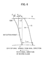
- the position of the inflection point is not limited. This case is described as a modified example of the first embodiment with reference to Fig. 6 .
- Fig. 6 is a meridian cross-sectional view of a main structure of a turbine stage according to the modified example of the first embodiment of the present invention. Parts that are the same as the parts described in the first embodiment are indicated by the same reference numerals, and a description thereof is omitted. As illustrated in Fig. 6 , an inflection point of a tangential lean is located on a trailing edge curved line 10A according to the modified example on the inner circumferential side with respect to the center of the stator vane in the height direction of the stator vane.
- the projecting amount on the outer circumferential side also affects the degree of reaction on the inner circumferential side.
- the number of processes for design tends to increase, compared to the first embodiment in which the degree of reaction on the inner circumferential side and the degree of reaction on the outer circumferential side are independently controlled.
- Fig. 7 is a meridian cross-sectional view of a main structure of a turbine stage according to the second embodiment of the present invention. Constituent elements that are the same as the first embodiment are indicated by the same reference numerals, and a description thereof is omitted.
- the second embodiment is different from the first embodiment in a change (or axial lean) in the trailing edge curved line of the stator vane in the axial direction of the turbine rotor 17.
- a steam turbine illustrated in Fig. 7 has a stator vane 1B.
- a curved line 10B is a curved line represented by rotationally projecting a trailing edge curved line of the stator vane 1B on a meridian surface (surface of the turbine rotor taken along the central axis of the turbine rotor (or the surface of the paper sheet of Fig. 7 )) of the steam turbine.
- the curved line 10B is also called a "meridian surface curved line" for convenience.
- a straight line 21 is a line that connects both ends (tip portion and root portion of the stator vane 1B) of the meridian surface curved line 10B. As illustrated in Fig.
- the straight line 21 according to the present embodiment and the meridian surface curved line 10B according to the present embodiment cross each other at the tip portion of the stator vane 1B so that the straight line 21 and the meridian surface curved line 10B form a predetermined angle (inclination angle ⁇ ) on the downstream side of the flow of the working fluid with respect to the straight line 21.
- Fig. 8A The tangential lean on the side of the tip portion of the stator vane 1B according to the present embodiment is illustrated in Fig. 8A
- Fig. 8B the axial lean on the side of the tip portion of the stator vane 1B according to the present embodiment is illustrated in Fig. 8B .
- Solid lines of Figs. 8A and 8B each indicate the shape of the stator vane on the side of the tip portion
- broken lines of Figs. 8A and 8B each indicate the shape of the stator vane on the side of the root portion.
- FIGS. 8A and 8B indicate a flow direction of working steam.
- a "circumferential direction” that is illustrated in each of Figs. 8A and 8B indicates a circumferential direction of the steam turbine, while an “axial direction” that is illustrated in each of Figs. 8A and 8B indicates an axial direction of the steam turbine.
- a direction of an arrow that points in the "circumferential direction” illustrated in each of Figs. 8A and 8B matches the rotational direction of the moving blade.
- the tangential lean of the stator vane 1B is inclined in the circumferential direction on the side of the tip portion of the stator vane 1B and the pressure side in the same manner as the first embodiment, and a projecting amount of the tangential lean in the rotational direction of the moving blade increases toward the tip portion of the stator vane 1B.
- the axial lean of the stator vane 1B is inclined in the axial direction on the side of the tip portion of the stator vane 1B and the pressure side and forms the inclination angle ⁇ with the straight line 21 on the downstream side of the flow of the working steam in the flow direction 20 of the working steam (working fluid).
- the inclination angle of a first half of the tangential lean of the stator vane 1B is large, and the inclination angle of a second half of the axial lean of the stator vane 1B is large.
- the tangential lean causes a force to act on the working steam on the side of the root portion and the upstream side of the stator vane 1B.
- the axial lean causes a force to act on the working steam on the side of the root portion and the downstream side of the stator vane 1B.
- the reduction in the degree of reaction on the outer circumferential side of the stator vane and the suppression of the supersonic inflow are achieved by combining the tangential lean of the stator vane with the axial lean of the stator vane.
- the stator vane 1B is formed so that the projection amount in the circumferential direction of the turbine rotor and the projection amount in the axial direction of the turbine rotor increase toward the outer circumferential side of the turbine rotor.
- a velocity component of the working steam in an inner diameter direction occurs around the outer circumferential part of the stator vane 1B, and whereby the degree of reaction on the outer circumferential side can be reduced by the same principle as described in the first embodiment.
- the supersonic flow of the working steam into the region in which the moving blades rotate is suppressed.
- the turbine efficiency can be improved.
- stator vane according to the present embodiment When the stator vane according to the present embodiment is installed in the turbine stage provided with the moving blade that causes the moving blade outer circumferential end portion Mach number (which is obtained by dividing the rotational circumferential velocity of the outer circumferential inlet portion of the moving blade by the velocity of sound in the steam flowing into a region in which the outer circumferential end portion of the moving blade rotates) to be larger than 1.0, a profile loss due to a shock wave is suppressed, and the turbine efficiency is improved.
- Mach number which is obtained by dividing the rotational circumferential velocity of the outer circumferential inlet portion of the moving blade by the velocity of sound in the steam flowing into a region in which the outer circumferential end portion of the moving blade rotates
- the tangential lean and the axial lean have an effect of reducing the degree of reaction on the side (outer circumferential side) of the tip portion of the stator vane.
- the projecting amount of the tangential lean is smaller, compared to the first embodiment in which the tangential lean is independently provided.
- a profile loss due to the secondary radial flow can be reduced in the second embodiment in which the radial flow is generated by the leading edge and trailing edge of the stator vane, compared to the first embodiment in which the radial flow is generated by the leading edge of the stator vane.
- a flow pattern in the radial direction can be improved by the thus-configured steam turbine stator vane according to the present embodiment even when the lengths of the blades are increased.
- the degree of reaction on the inner circumferential side of the stator vane can be set to an appropriate degree, and a profile loss due to the radial flow and the like can be reduced without an increase in the length of the shaft of the turbine.
- the turbine efficiency can be improved by the steam turbine stator vane according to the present embodiment.
- the moving blade may not be provided with the shroud cover. Even when the moving blade is not provided with the shroud cover, the effect described in the embodiment and the like are less changed.
Landscapes
- Engineering & Computer Science (AREA)
- Physics & Mathematics (AREA)
- Fluid Mechanics (AREA)
- Mechanical Engineering (AREA)
- General Engineering & Computer Science (AREA)
- Turbine Rotor Nozzle Sealing (AREA)
Applications Claiming Priority (1)
| Application Number | Priority Date | Filing Date | Title |
|---|---|---|---|
| JP2010216336 | 2010-09-28 |
Publications (2)
| Publication Number | Publication Date |
|---|---|
| EP2434094A2 true EP2434094A2 (de) | 2012-03-28 |
| EP2434094A3 EP2434094A3 (de) | 2018-02-21 |
Family
ID=44582687
Family Applications (1)
| Application Number | Title | Priority Date | Filing Date |
|---|---|---|---|
| EP11181062.8A Withdrawn EP2434094A3 (de) | 2010-09-28 | 2011-09-13 | Leitschaufel für Dampfturbine und Dampfturbine |
Country Status (3)
| Country | Link |
|---|---|
| US (1) | US9011084B2 (de) |
| EP (1) | EP2434094A3 (de) |
| JP (1) | JP5592326B2 (de) |
Cited By (3)
| Publication number | Priority date | Publication date | Assignee | Title |
|---|---|---|---|---|
| CN103806946A (zh) * | 2013-10-30 | 2014-05-21 | 杭州汽轮机股份有限公司 | 排汽面积2.1m2变转速工业汽轮机低压级组末级叶片 |
| EP2893143A4 (de) * | 2012-09-05 | 2015-11-04 | United Technologies Corp | Fussbogengeometrie für flügelförmige schaufel |
| EP3530880A1 (de) * | 2018-02-26 | 2019-08-28 | MTU Aero Engines GmbH | Leitschaufelblatt mit geneigtem abschnitt, zugehöriges leitschaufelsegment, modul, strömungsmaschine und verfahren zum entwerfen eines moduls |
Families Citing this family (7)
| Publication number | Priority date | Publication date | Assignee | Title |
|---|---|---|---|---|
| JP5868605B2 (ja) | 2011-03-30 | 2016-02-24 | 三菱重工業株式会社 | ガスタービン |
| EP2669475B1 (de) * | 2012-06-01 | 2018-08-01 | Safran Aero Boosters SA | S-Profil-Laufschaufel für Verdichter einer axialen Strömungsmaschine, zugehöriger Verdichter und Strömungsmaschine |
| EP2685050B1 (de) | 2012-07-11 | 2017-02-01 | General Electric Technology GmbH | Leitschaufelanordnung für eine axialturbine |
| EP3081751B1 (de) * | 2015-04-14 | 2020-10-21 | Ansaldo Energia Switzerland AG | Gekühlte turbinenschaufel und verfahren zur herstellung dieser schaufel |
| CN106246234A (zh) * | 2016-08-01 | 2016-12-21 | 杭州汽轮机股份有限公司 | 一种高背压空冷汽轮机用末级动叶片 |
| KR101997985B1 (ko) | 2017-10-27 | 2019-07-08 | 두산중공업 주식회사 | 변형된 제이 타입 캔틸레버드 베인 및 이를 포함하는 가스 터빈 |
| JP7104379B2 (ja) | 2019-02-07 | 2022-07-21 | 株式会社Ihi | 軸流型のファン、圧縮機及びタービンの翼の設計方法、並びに、当該設計により得られる翼 |
Citations (7)
| Publication number | Priority date | Publication date | Assignee | Title |
|---|---|---|---|---|
| JPH10131707A (ja) | 1996-10-28 | 1998-05-19 | Hitachi Ltd | 軸流型タービン翼群 |
| US6099248A (en) | 1997-11-17 | 2000-08-08 | Abb Alstom Power (Switzerland) Ltd | Output stage for an axial-flow turbine |
| JP2003027901A (ja) | 2001-07-13 | 2003-01-29 | Mitsubishi Heavy Ind Ltd | 軸流タービン |
| JP2005005784A (ja) | 2003-06-09 | 2005-01-06 | Olympus Corp | 記録媒体収納装置及びカメラ |
| US20070071606A1 (en) | 2003-07-09 | 2007-03-29 | Donald Borthwick | Turbine blade |
| JP2009121468A (ja) | 2007-11-09 | 2009-06-04 | Alstom Technology Ltd | 蒸気タービン |
| EP2075408A2 (de) | 2007-12-28 | 2009-07-01 | Ansaldo Energia S.P.A. | Leitschaufel auf letzter Stufe des Niederdruckabschnitts einer Dampfturbine |
Family Cites Families (10)
| Publication number | Priority date | Publication date | Assignee | Title |
|---|---|---|---|---|
| FR2505399A1 (fr) * | 1981-05-05 | 1982-11-12 | Alsthom Atlantique | Aubage directeur pour veines divergentes de turbine a vapeur |
| US4616975A (en) * | 1984-07-30 | 1986-10-14 | General Electric Company | Diaphragm for a steam turbine |
| JP3005839B2 (ja) | 1992-12-24 | 2000-02-07 | 株式会社日立製作所 | 軸流タービン |
| JP4090613B2 (ja) | 1999-02-26 | 2008-05-28 | 株式会社東芝 | 軸流タービン |
| JP3626899B2 (ja) | 2000-08-10 | 2005-03-09 | 三菱重工業株式会社 | タービン翼間の端壁構造 |
| US7547187B2 (en) * | 2005-03-31 | 2009-06-16 | Hitachi, Ltd. | Axial turbine |
| JP4869974B2 (ja) | 2005-03-31 | 2012-02-08 | 株式会社日立製作所 | 軸流タービン |
| US7140832B2 (en) | 2005-04-04 | 2006-11-28 | General Electric Company | Method and system for rotating a turbine stator ring |
| WO2007113149A1 (de) * | 2006-03-31 | 2007-10-11 | Alstom Technology Ltd | Leitschaufel für eine strömungsmaschine, insbesondere für eine dampfturbine |
| US7806653B2 (en) * | 2006-12-22 | 2010-10-05 | General Electric Company | Gas turbine engines including multi-curve stator vanes and methods of assembling the same |
-
2011
- 2011-09-13 EP EP11181062.8A patent/EP2434094A3/de not_active Withdrawn
- 2011-09-13 US US13/231,860 patent/US9011084B2/en not_active Expired - Fee Related
- 2011-09-28 JP JP2011212168A patent/JP5592326B2/ja not_active Expired - Fee Related
Patent Citations (7)
| Publication number | Priority date | Publication date | Assignee | Title |
|---|---|---|---|---|
| JPH10131707A (ja) | 1996-10-28 | 1998-05-19 | Hitachi Ltd | 軸流型タービン翼群 |
| US6099248A (en) | 1997-11-17 | 2000-08-08 | Abb Alstom Power (Switzerland) Ltd | Output stage for an axial-flow turbine |
| JP2003027901A (ja) | 2001-07-13 | 2003-01-29 | Mitsubishi Heavy Ind Ltd | 軸流タービン |
| JP2005005784A (ja) | 2003-06-09 | 2005-01-06 | Olympus Corp | 記録媒体収納装置及びカメラ |
| US20070071606A1 (en) | 2003-07-09 | 2007-03-29 | Donald Borthwick | Turbine blade |
| JP2009121468A (ja) | 2007-11-09 | 2009-06-04 | Alstom Technology Ltd | 蒸気タービン |
| EP2075408A2 (de) | 2007-12-28 | 2009-07-01 | Ansaldo Energia S.P.A. | Leitschaufel auf letzter Stufe des Niederdruckabschnitts einer Dampfturbine |
Cited By (5)
| Publication number | Priority date | Publication date | Assignee | Title |
|---|---|---|---|---|
| EP2893143A4 (de) * | 2012-09-05 | 2015-11-04 | United Technologies Corp | Fussbogengeometrie für flügelförmige schaufel |
| CN103806946A (zh) * | 2013-10-30 | 2014-05-21 | 杭州汽轮机股份有限公司 | 排汽面积2.1m2变转速工业汽轮机低压级组末级叶片 |
| CN103806946B (zh) * | 2013-10-30 | 2016-08-17 | 杭州汽轮机股份有限公司 | 排汽面积2.1m2变转速工业汽轮机低压级组末级叶片 |
| EP3530880A1 (de) * | 2018-02-26 | 2019-08-28 | MTU Aero Engines GmbH | Leitschaufelblatt mit geneigtem abschnitt, zugehöriges leitschaufelsegment, modul, strömungsmaschine und verfahren zum entwerfen eines moduls |
| US11220911B2 (en) | 2018-02-26 | 2022-01-11 | MTU Aero Engines AG | Guide vane airfoil for the hot gas flow path of a turbomachine |
Also Published As
| Publication number | Publication date |
|---|---|
| US20120076646A1 (en) | 2012-03-29 |
| JP2012092825A (ja) | 2012-05-17 |
| EP2434094A3 (de) | 2018-02-21 |
| US9011084B2 (en) | 2015-04-21 |
| JP5592326B2 (ja) | 2014-09-17 |
Similar Documents
| Publication | Publication Date | Title |
|---|---|---|
| EP2434094A2 (de) | Leitschaufel für Dampfturbine und Dampfturbine | |
| CN103180617B (zh) | 跨音速叶片 | |
| JP5946707B2 (ja) | 軸流タービン動翼 | |
| JP5777531B2 (ja) | 軸流ターボ機械用のエーロフォイル羽根 | |
| US10539154B2 (en) | Compressor end-wall treatment having a bent profile | |
| CN103261700B (zh) | 具有优化的积叠规律的涡轮发动机叶片 | |
| JP5603800B2 (ja) | タービン静翼、およびそれを用いた蒸気タービン設備 | |
| US9004850B2 (en) | Twisted variable inlet guide vane | |
| US20120009065A1 (en) | Rotor blade | |
| CN104854325A (zh) | 辐流式涡轮动叶片 | |
| JP6017033B2 (ja) | 半径流入式軸流タービン及びターボチャージャ | |
| JP7266610B2 (ja) | 鋸歯状プロファイルを有する流れ分離スラットを有する、ターボ機械 | |
| JP2016539276A (ja) | 遠心圧縮機の湾曲した拡散流路部 | |
| JP2012031864A (ja) | 低圧蒸気タービン及び低圧蒸気タービンを運転する方法 | |
| JP2017193985A (ja) | タービンインペラ | |
| JP5314441B2 (ja) | 遠心型水力機械 | |
| JP4869974B2 (ja) | 軸流タービン | |
| JP5398515B2 (ja) | ラジアルタービンの動翼 | |
| JP5201333B2 (ja) | 可変ノズルのベーン形状及び可変容量過給機 | |
| JP6518526B2 (ja) | 軸流タービン | |
| JP2009036112A (ja) | 回転機械の翼 | |
| JP4918455B2 (ja) | ターボチャージャー | |
| JP6684593B2 (ja) | 軸流タービン | |
| KR102941664B1 (ko) | 터빈 휠 | |
| JPH11173104A (ja) | タービン動翼 |
Legal Events
| Date | Code | Title | Description |
|---|---|---|---|
| PUAI | Public reference made under article 153(3) epc to a published international application that has entered the european phase |
Free format text: ORIGINAL CODE: 0009012 |
|
| AK | Designated contracting states |
Kind code of ref document: A2 Designated state(s): AL AT BE BG CH CY CZ DE DK EE ES FI FR GB GR HR HU IE IS IT LI LT LU LV MC MK MT NL NO PL PT RO RS SE SI SK SM TR |
|
| AX | Request for extension of the european patent |
Extension state: BA ME |
|
| 17P | Request for examination filed |
Effective date: 20120302 |
|
| RIN1 | Information on inventor provided before grant (corrected) |
Inventor name: ONO, HIDEKI Inventor name: MURATA, KENICHI Inventor name: SENOO, SHIGEKI Inventor name: LEE, GOINGWON |
|
| RAP1 | Party data changed (applicant data changed or rights of an application transferred) |
Owner name: MITSUBISHI HITACHI POWER SYSTEMS, LTD. |
|
| RAP1 | Party data changed (applicant data changed or rights of an application transferred) |
Owner name: MITSUBISHI HITACHI POWER SYSTEMS, LTD. |
|
| PUAL | Search report despatched |
Free format text: ORIGINAL CODE: 0009013 |
|
| AK | Designated contracting states |
Kind code of ref document: A3 Designated state(s): AL AT BE BG CH CY CZ DE DK EE ES FI FR GB GR HR HU IE IS IT LI LT LU LV MC MK MT NL NO PL PT RO RS SE SI SK SM TR |
|
| AX | Request for extension of the european patent |
Extension state: BA ME |
|
| RIC1 | Information provided on ipc code assigned before grant |
Ipc: F01D 5/14 20060101AFI20180115BHEP |
|
| STAA | Information on the status of an ep patent application or granted ep patent |
Free format text: STATUS: THE APPLICATION HAS BEEN WITHDRAWN |
|
| 18W | Application withdrawn |
Effective date: 20200310 |