EP2434166A2 - Pince de support en tôle - Google Patents
Pince de support en tôle Download PDFInfo
- Publication number
- EP2434166A2 EP2434166A2 EP11007375A EP11007375A EP2434166A2 EP 2434166 A2 EP2434166 A2 EP 2434166A2 EP 11007375 A EP11007375 A EP 11007375A EP 11007375 A EP11007375 A EP 11007375A EP 2434166 A2 EP2434166 A2 EP 2434166A2
- Authority
- EP
- European Patent Office
- Prior art keywords
- carrier
- support
- wedge
- support bracket
- sheet metal
- Prior art date
- Legal status (The legal status is an assumption and is not a legal conclusion. Google has not performed a legal analysis and makes no representation as to the accuracy of the status listed.)
- Granted
Links
Images




Classifications
-
- F—MECHANICAL ENGINEERING; LIGHTING; HEATING; WEAPONS; BLASTING
- F16—ENGINEERING ELEMENTS AND UNITS; GENERAL MEASURES FOR PRODUCING AND MAINTAINING EFFECTIVE FUNCTIONING OF MACHINES OR INSTALLATIONS; THERMAL INSULATION IN GENERAL
- F16B—DEVICES FOR FASTENING OR SECURING CONSTRUCTIONAL ELEMENTS OR MACHINE PARTS TOGETHER, e.g. NAILS, BOLTS, CIRCLIPS, CLAMPS, CLIPS OR WEDGES; JOINTS OR JOINTING
- F16B2/00—Friction-grip releasable fastenings
- F16B2/02—Clamps, i.e. with gripping action effected by positive means other than the inherent resistance to deformation of the material of the fastening
- F16B2/06—Clamps, i.e. with gripping action effected by positive means other than the inherent resistance to deformation of the material of the fastening external, i.e. with contracting action
- F16B2/065—Clamps, i.e. with gripping action effected by positive means other than the inherent resistance to deformation of the material of the fastening external, i.e. with contracting action using screw-thread elements
-
- F—MECHANICAL ENGINEERING; LIGHTING; HEATING; WEAPONS; BLASTING
- F16—ENGINEERING ELEMENTS AND UNITS; GENERAL MEASURES FOR PRODUCING AND MAINTAINING EFFECTIVE FUNCTIONING OF MACHINES OR INSTALLATIONS; THERMAL INSULATION IN GENERAL
- F16B—DEVICES FOR FASTENING OR SECURING CONSTRUCTIONAL ELEMENTS OR MACHINE PARTS TOGETHER, e.g. NAILS, BOLTS, CIRCLIPS, CLAMPS, CLIPS OR WEDGES; JOINTS OR JOINTING
- F16B2/00—Friction-grip releasable fastenings
- F16B2/02—Clamps, i.e. with gripping action effected by positive means other than the inherent resistance to deformation of the material of the fastening
- F16B2/14—Clamps, i.e. with gripping action effected by positive means other than the inherent resistance to deformation of the material of the fastening using wedges
Definitions
- the present invention relates to a carrier clip, a method of manufacturing a carrier clip, and uses relating to a carrier clip.
- Carrier clips have been used for a long time and in large numbers as fasteners, especially in the construction industry. They are usually clamped to supports, in particular steel beams, with a profile and / or a flange.
- Carrier brackets are used for example for fastening pipes and pipes and in particular sprinkler systems to supports. It is advantageous that a viable attachment can be done without welding or drilling; even retrospective alignment is possible.
- FIGS. 1a and 1b show conventional support brackets. Two ends 11 are integrally connected via a back 10. As in FIG. 1b can be seen, the ends 11 of a support bracket may comprise a carrier 2. To attach the carrier bracket to the carrier 2 is one of the ends of the 11th penetrating screw 12 and screw 12 is provided. At the in FIG. 1 shown support brackets, the back has a bore 13 or a thread 13 for receiving about a threaded rod or a threaded anchor (not shown here) on. So the objects to be fastened can be hung.
- Support brackets are conventionally made of malleable cast iron.
- Malleable cast iron has better mechanical properties compared to normal cast iron and is particularly tough, but can be processed comparatively well.
- the invention is based on the finding that malleable cast iron has disadvantages as a material for carrier brackets. For example, the number of manufacturers for support brackets made of malleable cast iron is very limited. If a manufacturer fails, then a sufficient supply of support brackets is no longer guaranteed.
- FIG. 2a shows where the weakest cross-section of a conventional beam clamp is and where it normally breaks when overloaded.
- the ductility of the material is limited.
- the FIG. 2a shows that hardly any deformation occurred before the fracture. Overloading a conventional bracket can cause a spontaneous break.
- FIG. 2b shows a conventional support bracket, which was broken due to voids formation in a test. Foul fractures are also problematic, which are also due to casting defects. Voids and septic breaks are often not recognized, as samples have shown.
- malleable iron is relatively expensive and must also be processed mechanically, which further increases the cost of manufacturing. So usually different holes are to be introduced and cut a thread.
- the object of the invention is to provide a particularly cost-effective and mechanically particularly advantageous teaching regarding support brackets.
- the invention is based on the idea to replace the malleable cast iron of the conventional support brackets by sheet metal.
- Sheet metal can be produced inexpensively in large quantities as a ready-to-roll metal product and is provided by a wide variety of manufacturers; usually as a blackboard or as a band.
- the object is achieved by a support bracket for clamping to a support with a projecting from a back end for abutment against the carrier and a fixing means for fixing the support bracket, wherein the end rests against the support.
- the support bracket is characterized in that the end and the back are formed with sheet metal.
- the back and the end of sheet metal are integrally formed.
- the support brackets according to the invention are intended to be suitable for clamping to a support, so that a payload, such as a part of a sprinkler system, can be fastened to the support via such a support bracket.
- the supports may be conventional supports, in particular typical and widespread builders or steel beams having a profile, flange or, generally, a projection or projection to which the support bracket may be clamped.
- a brackets on the optionally non-carrier abragment itself is possible.
- the carrier is clamped or the carrier clamp is fixed to the carrier and does not necessarily mention the optionally used projection.
- the carrier clamp rests against the carrier with the end projecting from the spine and is fixed to the carrier with the aid of the fixing means.
- the fixing means may be, for example, the above-mentioned screw or adjusting screw which is guided by a second end projecting from the back. But the invention also relates to alternative fixatives (s.u.).
- the back is preferably laterally from the carrier.
- an anchoring in particular a threaded rod or a threaded anchor, a bore or a thread may be provided on or in the back.
- the clamped carrier lies between the adjacent end and the Fixative. He is trapped between this end and the fixative. In other words, the carrier is gripped by the end abutting the carrier and the fixing means.
- sheet metal In contrast to malleable iron, sheet metal does not break abruptly, but allows a significant deformation. Voids and other casting defects can not occur when produced from sheet metal.
- Sheet metal is easy to work with and can be obtained from a variety of manufacturers.
- the supply of support brackets according to the invention is therefore safer guaranteed.
- Sheet metal is lightweight, has favorable mechanical properties and can be adapted to a wide range of requirements by suitably selecting the thickness, geometry and material. For example, a sufficiently strong sheet of stainless steel can be selected for particularly strong planned load. Regardless, a preferred choice is also galvanized sheet steel. An adaptation of the geometry opens up a variety of clamping possibilities. So far, carrier clamps with three fixed sizes have been used for flange thicknesses up to 25 mm. The properties of the carrier clamps according to the invention enable a greater choice of different configurations or even a task-specific production or adaptation.
- the conventional design with two ends connected together by a spine for embracing the carrier is retained for the invention.
- the support bracket is then characterized in that the two ends and the back are formed with sheet metal.
- the back and both ends are made of sheet metal.
- the back and both ends are integrally formed.
- the carrier clamp has two ends protruding from the back, these ends are located at a distance from one another; preferably, but not necessarily, both ends lie in the same plane.
- the two opposite sides of the ends determine the maximum span with which to staple.
- At least one of the two inner sides is suitable for contact with the carrier.
- the insides of both ends are designed to rest on the wearer (see below).
- the spine and the end or ends are made from prepunched sheet metal.
- the support bracket must then be transformed only in its final form; for example by bending.
- the back has a U-shape.
- This shape is mechanically very stable and can be easily manufactured by bending the sheet. It is preferred if the end or the ends are each formed as an extension of the legs of the U-shape of the back or are. Each end may then have two adjacent struts projecting from the spine. When the carrier is gripped, the legs of the U constituting the ends are facing the carrier and the base of the U connecting the legs faces away from the carrier.
- each strut it is preferred to provide the inner sides of the ends in each case with a toothing. This allows a secure investment.
- the Attachment made either with the inside of one end or with the inside of the other end; possibly even with both insides. If an end is formed with two adjacent struts, it is preferred to provide each strut with a toothing on the inside.
- support brackets with screws can be particularly problematic in terms of handling. If, for example, a conventional carrier clamp is fastened to a carrier by means of an adjusting screw, the pressure point of the screw forms a pivot point on the carrier. When tightening the screw, the rotation transfers to the support bracket and this twists. This complicates the straight and proper attachment of the support bracket; The overhead work is already difficult and demanding anyway.
- a particularly preferred embodiment of the invention is based on the idea of replacing the conventional screw connection by a wedging, that is to say a connection with a wedge.
- Wedge connections are basically known from other technical fields. In scaffolding, they are known as dynamic and highly resilient compounds.
- the screw so in particular the screw, the corresponding thread and a commonly used lock nut can be omitted.
- the support bracket has a wedge and an abutment for the wedge.
- the abutment is immovable relative to the spine of the carrier bracket and serves to abut the wedge.
- the end or one of the ends is applied to the support and the wedge is driven between the abutment and the support.
- the carrier is firmly gripped with or between the abutting end of the support bracket and the wedge.
- the carrier is clamped between the adjacent end of the support bracket and the wedge.
- the wedge can slide along the abutment during clamping.
- the wedge can be easily driven by striking between the abutment and the carrier. He is preferably guided past the back.
- the abutment extends along the end of the carrier bracket. If two ends are present, it is preferred if both ends have an abutment.
- the carrier clamp is so particularly flexible.
- an abutment may be formed by bending out a portion of an end from the plane of the tail and the spine; The bend is thus made transversely to the longitudinal direction of the corresponding end to the outside.
- a trough-shaped abutment can be formed particularly easily, which is preferred.
- the wedge is a double wedge.
- it can be U-shaped.
- the legs of the U each have a wedge shape and can be applied approximately on two spaced on both sides of the back located abutments of the support bracket.
- the two wedges are connected at their thicker end.
- the double wedge is used with a support bracket with U-shaped back. That's it preferred when the U-shape of the double wedge encapsulates the U-shape of the back.
- the wedge is designed so that it can not detach from the support bracket or fall off from it.
- one of the tapered ends may have a bent tab that will hang when dropped.
- the wedge or the double wedge consists of sheet metal.
- the invention also relates to a method for producing a carrier clip for stapling to a carrier comprising the steps of: forming a sheet to form a spine and an end projecting from the spine for abutment with the carrier.
- a support bracket with two ends are to be produced, it is preferable to reshape a metal sheet to form two ends which are connected to one another via a spine for the purpose of bordering a section of the support.
- the sheet is pre-punched. It is also preferable if the sheet is formed by bending into shape and the back and the end or the ends are integrally formed.
- the invention relates in particular to the use of sheet metal for producing a carrier clip.
- the invention also relates to the use of a wedge for fastening a carrier clip, in particular a carrier clip according to the invention, to a carrier.
- the support bracket made of sheet metal. It is also preferred if the wedge is made of sheet metal. Again, a double wedge is preferably used.
- the invention also relates to a system with a support bracket, in particular with a support bracket according to the invention, and a wedge.
- FIG. 3 shows a support bracket according to the invention with a
- Screw 12 as a fixative.
- the middle part of the figure shows the carrier bracket from the side. It recognizes the back 10, the ends 11 and the screw 12. Arrows A-A and B-B indicate corresponding cutting planes.
- the lower part of the figure shows a section along the A-A plane and the upper part of the figure shows a section along the B-B plane.
- Back 10 and ends 11 are made of pre-punched sheet metal and are bent in shape. The resulting U-shape is clearly visible in the A-A and B-B sections. Each end 11 is correspondingly made of two legs 14 of the U-shape.
- the back 10 includes the base 15 of the U-shape, so the bend of the sheet.
- the carrier (not shown here) is clamped by means of the screw 12 between the ends 11.
- the screw 12 has a set screw 16, a thread 17, a nut 18 for locking the system and a washer 19.
- the washer 19 abuts a pin 20 and prevents the screw 16 from slipping out of the end 11.
- the sheet of the support bracket has, for example, a thickness of 2, 3 or 4mm.
- the center of the adjusting screw 12 defines a central axis Z.
- the back has a length of 50 mm in the Z direction, the ends are each 10 mm wide in the Z direction.
- the pin 20 as well as the washer 19 has a height of 2 mm and the thread 17 has a depth of 8 mm.
- the set screw has a diameter of 10mm.
- the back starts at a distance of 13 mm from the Z-axis. With At a distance of 22 mm from the Z-axis, the bend of the spine 10 begins.
- the thread 17 has a distance of 22 mm to the inside of the opposite end 11.
- the legs 14 of the ends 11 have a maximum distance of 11 mm.
- the end 11 shown below in the middle figure is 10 mm shorter than the upper end 11.
- the left part of the FIG. 4 shows how falling out of the screw 12 by bending over the legs 14 can be prevented.
- the section shown is at level BB level FIG. 3 ,
- the middle and the right part of the FIG. 4 show a view from the marked in the left part of direction C.
- the leg ends are additionally interlocked.
- FIG. 5 shows a support bracket according to the invention with wedging in two views. In the upper view you can see the carrier bracket from the side. It can be seen how the carrier bracket is fixed with a double wedge 22 on a T-beam 2.
- the lower view shows the carrier bracket schematically in plan view.
- the lower part of the lower end 11 is rounded rounded groove-shaped outwardly to form an abutment 23 for the double wedge 22.
- the double wedge 22 is 23-guided when driving through the gutters of the abutment. Again, there remains an opening 21 for attachment of a payload.
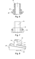
- FIG. 6 shows a section through the in the FIG. 5 marked level BB. It can be seen how the double wedge 22 is guided in the abutment 23 of the lower end 11.
- FIG. 7 shows an alternative embodiment for the abutment 23.
- the view corresponds to the in FIG. 5 marked with A view of a lower portion of the support bracket.
- FIG. 8 shows in perspective another carrier bracket according to the invention. It also has a back 10, ends 11 and a double wedge 22. Here are both the upper and the lower end equipped with an abutment 23. The inner sides of the ends 11 each have a toothing 24 (hidden below by the double wedge 22). The inner sides of the ends 11 of the support bracket correspond to sufficiently long contact surfaces to give a firm grip. The additional toothing which engages the surface of the carrier, can prevent slipping or loosening of the wedge connection.
- FIG. 9 schematically shows how a carrier bracket according to the invention with wedging a carrier 2 clings.
- a double wedge 22 is driven between an abutment 23 and the carrier 2.
- FIG. 10 schematically shows a further carrier clip according to the invention.
- a threaded anchor 25 is housed between the legs 14, the ends 11 and the carrier 2.
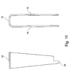
- FIG. 11 schematically shows a double wedge.
- the right part of the figure shows the double wedge in supervision. It can be clearly seen here the U-shape of the double wedge with the two legs 14 and the base 15 of U.
- the left part of the figure shows the double wedge from the side, so one of the legs 14 of the U-shape. You can clearly see the tapered wedge shape.
- the legs 14 are connected at their thick end on the base 15 of the U with each other.
- the double wedge is made of sheet metal, is pre-punched and bent into the U-shape.
- the double wedge is scaled (not shown) at its top and bottom. Every 5 mm a notch is inserted. Based on the scaling, the fitter can assess how deep the wedge is hammered.
- FIG. 12 shows three views of a back 10 with two projecting ends 11 of a carrier clip according to the invention.
- the bracket On the bottom left, the bracket is shown from the side. It has a back 10 and two ends 11. Each of the ends has an abutment 23 and an inside toothing 24.
Landscapes
- Engineering & Computer Science (AREA)
- General Engineering & Computer Science (AREA)
- Mechanical Engineering (AREA)
- Clamps And Clips (AREA)
Applications Claiming Priority (1)
| Application Number | Priority Date | Filing Date | Title |
|---|---|---|---|
| DE102010045961 | 2010-09-22 |
Publications (3)
| Publication Number | Publication Date |
|---|---|
| EP2434166A2 true EP2434166A2 (fr) | 2012-03-28 |
| EP2434166A3 EP2434166A3 (fr) | 2014-02-19 |
| EP2434166B1 EP2434166B1 (fr) | 2015-11-04 |
Family
ID=44680979
Family Applications (1)
| Application Number | Title | Priority Date | Filing Date |
|---|---|---|---|
| EP11007375.6A Active EP2434166B1 (fr) | 2010-09-22 | 2011-09-09 | Pince de support en tôle |
Country Status (3)
| Country | Link |
|---|---|
| EP (1) | EP2434166B1 (fr) |
| DE (1) | DE202011110297U1 (fr) |
| ES (1) | ES2558342T3 (fr) |
Cited By (1)
| Publication number | Priority date | Publication date | Assignee | Title |
|---|---|---|---|---|
| CN116771772A (zh) * | 2023-07-11 | 2023-09-19 | 合肥同智机电控制技术有限公司 | 一种齿形滑块锁紧装置及使用方法 |
Family Cites Families (5)
| Publication number | Priority date | Publication date | Assignee | Title |
|---|---|---|---|---|
| US1794976A (en) * | 1929-09-30 | 1931-03-03 | Mueller Electric Company | Clamp |
| SE403312B (sv) * | 1976-08-30 | 1978-08-07 | Skaraborgs Ror Ab | Klemfeste till ror med plana sidor |
| US4570885A (en) * | 1983-09-19 | 1986-02-18 | Tolco, Incorporated | Hanger clamp body and method of forming same |
| SE9200260D0 (sv) * | 1992-01-30 | 1992-01-30 | Reinklou Innovation Ab | Balkkilsfaeste |
| DE29619144U1 (de) * | 1996-11-05 | 1997-04-30 | Dick, Dietmar, Dipl.-Ing., 53840 Troisdorf | Trägerklammer |
-
2011
- 2011-09-09 EP EP11007375.6A patent/EP2434166B1/fr active Active
- 2011-09-09 DE DE201120110297 patent/DE202011110297U1/de not_active Expired - Lifetime
- 2011-09-09 ES ES11007375.6T patent/ES2558342T3/es active Active
Non-Patent Citations (1)
| Title |
|---|
| None |
Cited By (1)
| Publication number | Priority date | Publication date | Assignee | Title |
|---|---|---|---|---|
| CN116771772A (zh) * | 2023-07-11 | 2023-09-19 | 合肥同智机电控制技术有限公司 | 一种齿形滑块锁紧装置及使用方法 |
Also Published As
| Publication number | Publication date |
|---|---|
| EP2434166A3 (fr) | 2014-02-19 |
| DE202011110297U1 (de) | 2013-05-10 |
| ES2558342T3 (es) | 2016-02-03 |
| EP2434166B1 (fr) | 2015-11-04 |
Similar Documents
| Publication | Publication Date | Title |
|---|---|---|
| EP2199476B1 (fr) | Rails d'ancrage | |
| EP3081708B1 (fr) | Rail d'ancrage dans le béton | |
| DE8715256U1 (de) | Montageschieneneinheit | |
| EP0805297A2 (fr) | Dispositif d'ancrage | |
| EP3081707A1 (fr) | Rail d'ancrage dans le béton et système de fixation doté d'un rail d'ancrage | |
| EP2756238B1 (fr) | Dispositif de fixation d'un rail de montage sur un crochet de toit | |
| EP2478163B1 (fr) | Rail d'ancrage à noyer | |
| EP2783437B1 (fr) | Rail support pour une armoire electrique | |
| EP1232312A1 (fr) | Dispositif support pour objets longitudinaux accroches a un batiment, en particulier, gouttieres de drainage de toiture | |
| EP2434166B1 (fr) | Pince de support en tôle | |
| EP3561353B1 (fr) | Dispositif de serrage | |
| WO2017144448A2 (fr) | Système d'essieu | |
| DE202011003315U1 (de) | Verbindungsvorrichtung | |
| EP1832802A2 (fr) | Pince d'encrage | |
| DE29619144U1 (de) | Trägerklammer | |
| DE202009012533U1 (de) | Eingiessbare Ankerschiene | |
| DE202013011471U1 (de) | Vorrichtung zur Befestigung eines Fensters oder einer Tür in einer Wandöffnung | |
| DE202011108692U1 (de) | Hohlprofil und Hallengerüst mit einem solchen Profil | |
| EP4131683A1 (fr) | Module d'un système de porte-câble | |
| EP0998613B1 (fr) | Listel a goujons pour armatures relevees | |
| EP2155516B1 (fr) | Jeu de barres de toit transversales prévu pour être fixé à des barres de toit longitudinales de moyens de transport | |
| EP3402993B1 (fr) | Systeme de montage dote de rail de montage et ecrou de retenue en saillie | |
| EP2458229A1 (fr) | Dispositif de connexion | |
| EP4145651B1 (fr) | Flèche à appui d'un seul côté d'extrémité pour un système de porte-câble | |
| DE102009007923B4 (de) | Halteeinrichtung für Druckluftkessel |
Legal Events
| Date | Code | Title | Description |
|---|---|---|---|
| REG | Reference to a national code |
Ref country code: DE Ref legal event code: R138 Ref document number: 202011110297 Country of ref document: DE Free format text: GERMAN DOCUMENT NUMBER IS 502011008249 Ref country code: DE Ref legal event code: R138 Ref document number: 502011008249 Country of ref document: DE Free format text: GERMAN DOCUMENT NUMBER IS 502011008249 |
|
| PUAI | Public reference made under article 153(3) epc to a published international application that has entered the european phase |
Free format text: ORIGINAL CODE: 0009012 |
|
| AK | Designated contracting states |
Kind code of ref document: A2 Designated state(s): AL AT BE BG CH CY CZ DE DK EE ES FI FR GB GR HR HU IE IS IT LI LT LU LV MC MK MT NL NO PL PT RO RS SE SI SK SM TR |
|
| AX | Request for extension of the european patent |
Extension state: BA ME |
|
| PUAL | Search report despatched |
Free format text: ORIGINAL CODE: 0009013 |
|
| AK | Designated contracting states |
Kind code of ref document: A3 Designated state(s): AL AT BE BG CH CY CZ DE DK EE ES FI FR GB GR HR HU IE IS IT LI LT LU LV MC MK MT NL NO PL PT RO RS SE SI SK SM TR |
|
| AX | Request for extension of the european patent |
Extension state: BA ME |
|
| RIC1 | Information provided on ipc code assigned before grant |
Ipc: F16B 2/14 20060101ALI20140113BHEP Ipc: F16B 2/06 20060101AFI20140113BHEP |
|
| 17P | Request for examination filed |
Effective date: 20140626 |
|
| RBV | Designated contracting states (corrected) |
Designated state(s): AL AT BE BG CH CY CZ DE DK EE ES FI FR GB GR HR HU IE IS IT LI LT LU LV MC MK MT NL NO PL PT RO RS SE SI SK SM TR |
|
| 17Q | First examination report despatched |
Effective date: 20150119 |
|
| GRAP | Despatch of communication of intention to grant a patent |
Free format text: ORIGINAL CODE: EPIDOSNIGR1 |
|
| INTG | Intention to grant announced |
Effective date: 20150424 |
|
| GRAS | Grant fee paid |
Free format text: ORIGINAL CODE: EPIDOSNIGR3 |
|
| GRAA | (expected) grant |
Free format text: ORIGINAL CODE: 0009210 |
|
| AK | Designated contracting states |
Kind code of ref document: B1 Designated state(s): AL AT BE BG CH CY CZ DE DK EE ES FI FR GB GR HR HU IE IS IT LI LT LU LV MC MK MT NL NO PL PT RO RS SE SI SK SM TR |
|
| REG | Reference to a national code |
Ref country code: GB Ref legal event code: FG4D Free format text: NOT ENGLISH |
|
| REG | Reference to a national code |
Ref country code: CH Ref legal event code: EP |
|
| REG | Reference to a national code |
Ref country code: AT Ref legal event code: REF Ref document number: 759405 Country of ref document: AT Kind code of ref document: T Effective date: 20151115 |
|
| REG | Reference to a national code |
Ref country code: IE Ref legal event code: FG4D Free format text: LANGUAGE OF EP DOCUMENT: GERMAN |
|
| REG | Reference to a national code |
Ref country code: DE Ref legal event code: R096 Ref document number: 502011008249 Country of ref document: DE |
|
| REG | Reference to a national code |
Ref country code: CH Ref legal event code: NV Representative=s name: SCHMAUDER AND PARTNER AG PATENT- UND MARKENANW, CH |
|
| REG | Reference to a national code |
Ref country code: ES Ref legal event code: FG2A Ref document number: 2558342 Country of ref document: ES Kind code of ref document: T3 Effective date: 20160203 |
|
| REG | Reference to a national code |
Ref country code: LT Ref legal event code: MG4D |
|
| REG | Reference to a national code |
Ref country code: NL Ref legal event code: FP |
|
| PG25 | Lapsed in a contracting state [announced via postgrant information from national office to epo] |
Ref country code: LT Free format text: LAPSE BECAUSE OF FAILURE TO SUBMIT A TRANSLATION OF THE DESCRIPTION OR TO PAY THE FEE WITHIN THE PRESCRIBED TIME-LIMIT Effective date: 20151104 Ref country code: IS Free format text: LAPSE BECAUSE OF FAILURE TO SUBMIT A TRANSLATION OF THE DESCRIPTION OR TO PAY THE FEE WITHIN THE PRESCRIBED TIME-LIMIT Effective date: 20160304 Ref country code: NO Free format text: LAPSE BECAUSE OF FAILURE TO SUBMIT A TRANSLATION OF THE DESCRIPTION OR TO PAY THE FEE WITHIN THE PRESCRIBED TIME-LIMIT Effective date: 20160204 Ref country code: HR Free format text: LAPSE BECAUSE OF FAILURE TO SUBMIT A TRANSLATION OF THE DESCRIPTION OR TO PAY THE FEE WITHIN THE PRESCRIBED TIME-LIMIT Effective date: 20151104 |
|
| PG25 | Lapsed in a contracting state [announced via postgrant information from national office to epo] |
Ref country code: RS Free format text: LAPSE BECAUSE OF FAILURE TO SUBMIT A TRANSLATION OF THE DESCRIPTION OR TO PAY THE FEE WITHIN THE PRESCRIBED TIME-LIMIT Effective date: 20151104 Ref country code: SE Free format text: LAPSE BECAUSE OF FAILURE TO SUBMIT A TRANSLATION OF THE DESCRIPTION OR TO PAY THE FEE WITHIN THE PRESCRIBED TIME-LIMIT Effective date: 20151104 Ref country code: PL Free format text: LAPSE BECAUSE OF FAILURE TO SUBMIT A TRANSLATION OF THE DESCRIPTION OR TO PAY THE FEE WITHIN THE PRESCRIBED TIME-LIMIT Effective date: 20151104 Ref country code: LV Free format text: LAPSE BECAUSE OF FAILURE TO SUBMIT A TRANSLATION OF THE DESCRIPTION OR TO PAY THE FEE WITHIN THE PRESCRIBED TIME-LIMIT Effective date: 20151104 Ref country code: PT Free format text: LAPSE BECAUSE OF FAILURE TO SUBMIT A TRANSLATION OF THE DESCRIPTION OR TO PAY THE FEE WITHIN THE PRESCRIBED TIME-LIMIT Effective date: 20160304 Ref country code: FI Free format text: LAPSE BECAUSE OF FAILURE TO SUBMIT A TRANSLATION OF THE DESCRIPTION OR TO PAY THE FEE WITHIN THE PRESCRIBED TIME-LIMIT Effective date: 20151104 Ref country code: GR Free format text: LAPSE BECAUSE OF FAILURE TO SUBMIT A TRANSLATION OF THE DESCRIPTION OR TO PAY THE FEE WITHIN THE PRESCRIBED TIME-LIMIT Effective date: 20160205 |
|
| PG25 | Lapsed in a contracting state [announced via postgrant information from national office to epo] |
Ref country code: CZ Free format text: LAPSE BECAUSE OF FAILURE TO SUBMIT A TRANSLATION OF THE DESCRIPTION OR TO PAY THE FEE WITHIN THE PRESCRIBED TIME-LIMIT Effective date: 20151104 |
|
| REG | Reference to a national code |
Ref country code: DE Ref legal event code: R097 Ref document number: 502011008249 Country of ref document: DE |
|
| PG25 | Lapsed in a contracting state [announced via postgrant information from national office to epo] |
Ref country code: DK Free format text: LAPSE BECAUSE OF FAILURE TO SUBMIT A TRANSLATION OF THE DESCRIPTION OR TO PAY THE FEE WITHIN THE PRESCRIBED TIME-LIMIT Effective date: 20151104 Ref country code: EE Free format text: LAPSE BECAUSE OF FAILURE TO SUBMIT A TRANSLATION OF THE DESCRIPTION OR TO PAY THE FEE WITHIN THE PRESCRIBED TIME-LIMIT Effective date: 20151104 Ref country code: RO Free format text: LAPSE BECAUSE OF FAILURE TO SUBMIT A TRANSLATION OF THE DESCRIPTION OR TO PAY THE FEE WITHIN THE PRESCRIBED TIME-LIMIT Effective date: 20151104 Ref country code: SK Free format text: LAPSE BECAUSE OF FAILURE TO SUBMIT A TRANSLATION OF THE DESCRIPTION OR TO PAY THE FEE WITHIN THE PRESCRIBED TIME-LIMIT Effective date: 20151104 Ref country code: SM Free format text: LAPSE BECAUSE OF FAILURE TO SUBMIT A TRANSLATION OF THE DESCRIPTION OR TO PAY THE FEE WITHIN THE PRESCRIBED TIME-LIMIT Effective date: 20151104 |
|
| PLBE | No opposition filed within time limit |
Free format text: ORIGINAL CODE: 0009261 |
|
| STAA | Information on the status of an ep patent application or granted ep patent |
Free format text: STATUS: NO OPPOSITION FILED WITHIN TIME LIMIT |
|
| REG | Reference to a national code |
Ref country code: FR Ref legal event code: PLFP Year of fee payment: 6 |
|
| 26N | No opposition filed |
Effective date: 20160805 |
|
| PG25 | Lapsed in a contracting state [announced via postgrant information from national office to epo] |
Ref country code: SI Free format text: LAPSE BECAUSE OF FAILURE TO SUBMIT A TRANSLATION OF THE DESCRIPTION OR TO PAY THE FEE WITHIN THE PRESCRIBED TIME-LIMIT Effective date: 20151104 |
|
| PG25 | Lapsed in a contracting state [announced via postgrant information from national office to epo] |
Ref country code: MC Free format text: LAPSE BECAUSE OF FAILURE TO SUBMIT A TRANSLATION OF THE DESCRIPTION OR TO PAY THE FEE WITHIN THE PRESCRIBED TIME-LIMIT Effective date: 20151104 |
|
| REG | Reference to a national code |
Ref country code: IE Ref legal event code: MM4A |
|
| PG25 | Lapsed in a contracting state [announced via postgrant information from national office to epo] |
Ref country code: IE Free format text: LAPSE BECAUSE OF NON-PAYMENT OF DUE FEES Effective date: 20160909 |
|
| PG25 | Lapsed in a contracting state [announced via postgrant information from national office to epo] |
Ref country code: LU Free format text: LAPSE BECAUSE OF NON-PAYMENT OF DUE FEES Effective date: 20160909 |
|
| REG | Reference to a national code |
Ref country code: FR Ref legal event code: PLFP Year of fee payment: 7 |
|
| PG25 | Lapsed in a contracting state [announced via postgrant information from national office to epo] |
Ref country code: HU Free format text: LAPSE BECAUSE OF FAILURE TO SUBMIT A TRANSLATION OF THE DESCRIPTION OR TO PAY THE FEE WITHIN THE PRESCRIBED TIME-LIMIT; INVALID AB INITIO Effective date: 20110909 Ref country code: CY Free format text: LAPSE BECAUSE OF FAILURE TO SUBMIT A TRANSLATION OF THE DESCRIPTION OR TO PAY THE FEE WITHIN THE PRESCRIBED TIME-LIMIT Effective date: 20151104 |
|
| PG25 | Lapsed in a contracting state [announced via postgrant information from national office to epo] |
Ref country code: MT Free format text: LAPSE BECAUSE OF FAILURE TO SUBMIT A TRANSLATION OF THE DESCRIPTION OR TO PAY THE FEE WITHIN THE PRESCRIBED TIME-LIMIT Effective date: 20151104 Ref country code: TR Free format text: LAPSE BECAUSE OF FAILURE TO SUBMIT A TRANSLATION OF THE DESCRIPTION OR TO PAY THE FEE WITHIN THE PRESCRIBED TIME-LIMIT Effective date: 20151104 Ref country code: MK Free format text: LAPSE BECAUSE OF FAILURE TO SUBMIT A TRANSLATION OF THE DESCRIPTION OR TO PAY THE FEE WITHIN THE PRESCRIBED TIME-LIMIT Effective date: 20151104 |
|
| PG25 | Lapsed in a contracting state [announced via postgrant information from national office to epo] |
Ref country code: BG Free format text: LAPSE BECAUSE OF FAILURE TO SUBMIT A TRANSLATION OF THE DESCRIPTION OR TO PAY THE FEE WITHIN THE PRESCRIBED TIME-LIMIT Effective date: 20151104 |
|
| REG | Reference to a national code |
Ref country code: FR Ref legal event code: PLFP Year of fee payment: 8 |
|
| PG25 | Lapsed in a contracting state [announced via postgrant information from national office to epo] |
Ref country code: AL Free format text: LAPSE BECAUSE OF FAILURE TO SUBMIT A TRANSLATION OF THE DESCRIPTION OR TO PAY THE FEE WITHIN THE PRESCRIBED TIME-LIMIT Effective date: 20151104 |
|
| PGFP | Annual fee paid to national office [announced via postgrant information from national office to epo] |
Ref country code: AT Payment date: 20220921 Year of fee payment: 12 |
|
| PGFP | Annual fee paid to national office [announced via postgrant information from national office to epo] |
Ref country code: BE Payment date: 20220921 Year of fee payment: 12 |
|
| PGFP | Annual fee paid to national office [announced via postgrant information from national office to epo] |
Ref country code: IT Payment date: 20220930 Year of fee payment: 12 Ref country code: ES Payment date: 20221005 Year of fee payment: 12 |
|
| PGFP | Annual fee paid to national office [announced via postgrant information from national office to epo] |
Ref country code: CH Payment date: 20220923 Year of fee payment: 12 |
|
| REG | Reference to a national code |
Ref country code: CH Ref legal event code: PL |
|
| REG | Reference to a national code |
Ref country code: AT Ref legal event code: MM01 Ref document number: 759405 Country of ref document: AT Kind code of ref document: T Effective date: 20230909 |
|
| REG | Reference to a national code |
Ref country code: BE Ref legal event code: MM Effective date: 20230930 |
|
| PG25 | Lapsed in a contracting state [announced via postgrant information from national office to epo] |
Ref country code: CH Free format text: LAPSE BECAUSE OF NON-PAYMENT OF DUE FEES Effective date: 20230930 |
|
| PG25 | Lapsed in a contracting state [announced via postgrant information from national office to epo] |
Ref country code: AT Free format text: LAPSE BECAUSE OF NON-PAYMENT OF DUE FEES Effective date: 20230909 |
|
| PG25 | Lapsed in a contracting state [announced via postgrant information from national office to epo] |
Ref country code: CH Free format text: LAPSE BECAUSE OF NON-PAYMENT OF DUE FEES Effective date: 20230930 Ref country code: AT Free format text: LAPSE BECAUSE OF NON-PAYMENT OF DUE FEES Effective date: 20230909 |
|
| PG25 | Lapsed in a contracting state [announced via postgrant information from national office to epo] |
Ref country code: BE Free format text: LAPSE BECAUSE OF NON-PAYMENT OF DUE FEES Effective date: 20230930 |
|
| REG | Reference to a national code |
Ref country code: ES Ref legal event code: FD2A Effective date: 20241028 |
|
| PG25 | Lapsed in a contracting state [announced via postgrant information from national office to epo] |
Ref country code: IT Free format text: LAPSE BECAUSE OF NON-PAYMENT OF DUE FEES Effective date: 20230909 |
|
| PG25 | Lapsed in a contracting state [announced via postgrant information from national office to epo] |
Ref country code: IT Free format text: LAPSE BECAUSE OF NON-PAYMENT OF DUE FEES Effective date: 20230909 |
|
| PG25 | Lapsed in a contracting state [announced via postgrant information from national office to epo] |
Ref country code: ES Free format text: LAPSE BECAUSE OF NON-PAYMENT OF DUE FEES Effective date: 20230910 |
|
| PG25 | Lapsed in a contracting state [announced via postgrant information from national office to epo] |
Ref country code: ES Free format text: LAPSE BECAUSE OF NON-PAYMENT OF DUE FEES Effective date: 20230910 |
|
| PGFP | Annual fee paid to national office [announced via postgrant information from national office to epo] |
Ref country code: DE Payment date: 20250926 Year of fee payment: 15 |
|
| PGFP | Annual fee paid to national office [announced via postgrant information from national office to epo] |
Ref country code: NL Payment date: 20250925 Year of fee payment: 15 |
|
| PGFP | Annual fee paid to national office [announced via postgrant information from national office to epo] |
Ref country code: GB Payment date: 20250925 Year of fee payment: 15 |
|
| PGFP | Annual fee paid to national office [announced via postgrant information from national office to epo] |
Ref country code: FR Payment date: 20250925 Year of fee payment: 15 |