EP2434171A1 - Système d'arbre de transmission - Google Patents
Système d'arbre de transmission Download PDFInfo
- Publication number
- EP2434171A1 EP2434171A1 EP10179954A EP10179954A EP2434171A1 EP 2434171 A1 EP2434171 A1 EP 2434171A1 EP 10179954 A EP10179954 A EP 10179954A EP 10179954 A EP10179954 A EP 10179954A EP 2434171 A1 EP2434171 A1 EP 2434171A1
- Authority
- EP
- European Patent Office
- Prior art keywords
- shaft
- housing
- bearing
- bearing housing
- drive shaft
- Prior art date
- Legal status (The legal status is an assumption and is not a legal conclusion. Google has not performed a legal analysis and makes no representation as to the accuracy of the status listed.)
- Withdrawn
Links
- 230000033001 locomotion Effects 0.000 claims abstract description 33
- 230000008878 coupling Effects 0.000 claims abstract description 13
- 238000010168 coupling process Methods 0.000 claims abstract description 13
- 238000005859 coupling reaction Methods 0.000 claims abstract description 13
- 238000000034 method Methods 0.000 claims description 10
- 239000003381 stabilizer Substances 0.000 claims description 6
- 238000001816 cooling Methods 0.000 claims description 4
- 230000008569 process Effects 0.000 description 4
- 238000009434 installation Methods 0.000 description 2
- 230000004308 accommodation Effects 0.000 description 1
- 230000009471 action Effects 0.000 description 1
- 230000005540 biological transmission Effects 0.000 description 1
- 239000011248 coating agent Substances 0.000 description 1
- 238000000576 coating method Methods 0.000 description 1
- 238000010276 construction Methods 0.000 description 1
- 239000002826 coolant Substances 0.000 description 1
- 238000010586 diagram Methods 0.000 description 1
- 230000001050 lubricating effect Effects 0.000 description 1
- 238000005461 lubrication Methods 0.000 description 1
- 230000004048 modification Effects 0.000 description 1
- 238000012986 modification Methods 0.000 description 1
Images


Classifications
-
- F—MECHANICAL ENGINEERING; LIGHTING; HEATING; WEAPONS; BLASTING
- F01—MACHINES OR ENGINES IN GENERAL; ENGINE PLANTS IN GENERAL; STEAM ENGINES
- F01D—NON-POSITIVE DISPLACEMENT MACHINES OR ENGINES, e.g. STEAM TURBINES
- F01D5/00—Blades; Blade-carrying members; Heating, heat-insulating, cooling or antivibration means on the blades or the members
- F01D5/02—Blade-carrying members, e.g. rotors
- F01D5/10—Anti- vibration means
-
- F—MECHANICAL ENGINEERING; LIGHTING; HEATING; WEAPONS; BLASTING
- F16—ENGINEERING ELEMENTS AND UNITS; GENERAL MEASURES FOR PRODUCING AND MAINTAINING EFFECTIVE FUNCTIONING OF MACHINES OR INSTALLATIONS; THERMAL INSULATION IN GENERAL
- F16C—SHAFTS; FLEXIBLE SHAFTS; ELEMENTS OR CRANKSHAFT MECHANISMS; ROTARY BODIES OTHER THAN GEARING ELEMENTS; BEARINGS
- F16C25/00—Bearings for exclusively rotary movement adjustable for wear or play
- F16C25/06—Ball or roller bearings
-
- F—MECHANICAL ENGINEERING; LIGHTING; HEATING; WEAPONS; BLASTING
- F16—ENGINEERING ELEMENTS AND UNITS; GENERAL MEASURES FOR PRODUCING AND MAINTAINING EFFECTIVE FUNCTIONING OF MACHINES OR INSTALLATIONS; THERMAL INSULATION IN GENERAL
- F16C—SHAFTS; FLEXIBLE SHAFTS; ELEMENTS OR CRANKSHAFT MECHANISMS; ROTARY BODIES OTHER THAN GEARING ELEMENTS; BEARINGS
- F16C35/00—Rigid support of bearing units; Housings, e.g. caps, covers
- F16C35/04—Rigid support of bearing units; Housings, e.g. caps, covers in the case of ball or roller bearings
- F16C35/06—Mounting or dismounting of ball or roller bearings; Fixing them onto shaft or in housing
- F16C35/07—Fixing them on the shaft or housing with interposition of an element
- F16C35/073—Fixing them on the shaft or housing with interposition of an element between shaft and inner race ring
-
- F—MECHANICAL ENGINEERING; LIGHTING; HEATING; WEAPONS; BLASTING
- F16—ENGINEERING ELEMENTS AND UNITS; GENERAL MEASURES FOR PRODUCING AND MAINTAINING EFFECTIVE FUNCTIONING OF MACHINES OR INSTALLATIONS; THERMAL INSULATION IN GENERAL
- F16C—SHAFTS; FLEXIBLE SHAFTS; ELEMENTS OR CRANKSHAFT MECHANISMS; ROTARY BODIES OTHER THAN GEARING ELEMENTS; BEARINGS
- F16C35/00—Rigid support of bearing units; Housings, e.g. caps, covers
- F16C35/04—Rigid support of bearing units; Housings, e.g. caps, covers in the case of ball or roller bearings
- F16C35/06—Mounting or dismounting of ball or roller bearings; Fixing them onto shaft or in housing
- F16C35/07—Fixing them on the shaft or housing with interposition of an element
- F16C35/077—Fixing them on the shaft or housing with interposition of an element between housing and outer race ring
-
- F—MECHANICAL ENGINEERING; LIGHTING; HEATING; WEAPONS; BLASTING
- F16—ENGINEERING ELEMENTS AND UNITS; GENERAL MEASURES FOR PRODUCING AND MAINTAINING EFFECTIVE FUNCTIONING OF MACHINES OR INSTALLATIONS; THERMAL INSULATION IN GENERAL
- F16C—SHAFTS; FLEXIBLE SHAFTS; ELEMENTS OR CRANKSHAFT MECHANISMS; ROTARY BODIES OTHER THAN GEARING ELEMENTS; BEARINGS
- F16C2326/00—Articles relating to transporting
- F16C2326/01—Parts of vehicles in general
- F16C2326/06—Drive shafts
Definitions
- the present invention relates to the field of power transmission, and more particularly, to a drive shaft system.
- FIGS 1A-1C illustrate a prior art drive shaft system 99 transmitting torque and rotation from a motor 60 through a coupling 50 to a rotor 70, e.g. of a compressor.
- Coupling 50 comprises two spring systems 51A, 51B ( Figure 1B ) that provide a flexible connection between the shaft of motor 60 and shaft 80.
- Drive shaft system 99 comprises a shaft 80 supported by at least two supports 65, 75 in a shaft housing 90.
- Supports 65, 75 comprise bearings 95, 98 (respectively) that position shaft 80 within shaft housing 90.
- rotor side support 75 has bearing 98 that is mounted in shaft housing 90, and motor side support 65 has bearing 95 that is preloaded by springs 97A. Preloading of bearing 95 prevents its skidding.
- Figure 2A illustrates a prior art configuration, in which rotor side bearing 98 is preloaded by springs 97B. At least one of supports 65, 75 enables some axial movement (for example into gap 81 in Figure 1C ) to accommodate thermal expansion of shaft 80.
- supports 65, 75 are loaded in an axial direction by the weights of rotor 70 and shaft 80 and in a radial direction by unbalance forces 81 illustrated in Figure 2 B.
- Two wear processes are possible in prior art drive shaft systems 99 that cause early failure at supports 65, 75 due to wear of the adjacent face of shaft housing 90 and outer rings 96 of bearings 95, 98 ( Figure 2B ).
- the first wear process results from a turning of at least one of bearings 95, 98 upon the action of radial forces associated with the starting of motor 60 in combination with the large moment of inertia of rotor 70 and the flexibility of coupling 50.
- the second wear process results from radial movements of at least one of bearings 95, 98 during the high frequency rotation of rotor 70.
- Gap 92 represents some freedom due to installation of bearings 95, 98 in shaft housing 90 without interference fit. Gap 92 further enables accommodation of shaft 80 expansion when bearing 98 is fixed. A similar gap may occur between the inner ring of bearings 95, 98 and shaft 80.
- Debris 93 that accumulates as result of the wear processes increases the friction between supports 65, 75 and shaft housing 90 and prevents axial movement.
- the system is susceptible to damage resulting from increased axial forces acting upon supports 65, 75, such as forces due to thermal expansion of shaft 80, damage that shortens the operation time of drive shaft system 99 or even causes complete failure and damage to rotor 70 and/or motor 60.
- Prior art comprises elements that mild wear, such as cooling drive shaft system 99, and lubricating or coating the contact areas between bearings 95, 98 and shaft housing 90, however these elements do not solve the fundamental problem.
- Embodiments of the present invention provide a drive shaft system comprising: a shaft connected to a motor via a coupling and arranged to transmit a rotary movement from the motor to the rotor, at least two supports arranged to position the shaft within a shaft housing, each support comprising at least one bearing, and at least one forcing element arranged to force at least one of the supports against at least one of: an inner side of the shaft housing, and an outer side of the shaft; such as to prevent turning of the at least one of the supports within the shaft housing while enabling axial movement of the shaft within the shaft housing.
- Figure 3A is a cross sectional side view of a drive shaft system 100, according to some embodiments of the invention.
- Drive shaft system 100 transmits torque and rotation from the motor through coupling 50 to the rotor.
- Coupling 50 comprises two spring systems 51A, 51B that provide a flexible connection between the motor shaft and shaft 80.
- Shaft 80 is supported by at least motor side support 65 comprising bearings 95 (two bearings 95A and 95B in the illustrated example) and rotor side support 75 comprising bearing 98, supports 65, 75 position shaft 80 within shaft housing 90, such that at least one of supports is axially movable to accommodate axial thermal expansion of shaft 80.
- Supports 65, 75 are arranged in the current invention to withstand without wear the following forces: the load resulting from the rotor and shaft 80's weight, a turning force during motor starts that is transmitted by flexible coupling 50, and radial unbalance forces during rotation of shaft 80.
- Figures 3B and 3C illustrate details of forcing elements 135, 145 in drive shaft system 100 in cross sectional side views, according to some embodiments of the invention.
- Forcing elements 135 ( Figure 3C ) is arranged to force at least one of supports 65, 75 (e.g. outer rings 96 of bearings 95, 98) against the inner side of shaft housing 90 such as to prevent turning of supports 65, 75 (e.g. bearings 95, 98) within shaft housing 90 while enabling axial movement of at least one of supports 65, 75 (e.g. bearings 95, 98) within shaft housing 90 to accommodate thermal expansion of shaft 80.
- Forcing element 145 ( Figure 3B ) is arranged to force at least one of supports 65, 75 (e.g. bearings 95, 98) against the outer side of shaft 80 such as to prevent turning of supports 65, 75 (e.g. inner rings 94 of bearings 95, 98) in respect to shaft 80.
- Forcing element 145 is arranged to enable thermal expansion of shaft 80.
- Figure 3B illustrates an embodiment of forcing element 145 as a spring unit 147 installed within shaft 80 and forcing (by force 134B) inner ring 94 of bearing 98 against the outer face of shaft 80.
- Spring unit 147 is connected to shaft 80 via a screw 146 and presses plate 148 against inner ring 94 of bearing 98.
- Forcing element 145 may comprise several spring units 147 installed around the perimeter of shaft 80 and forcing inner ring 94 at different points.
- Forcing elements 145 may be installed in shaft 80 in contact with either motor side support 65 (bearings 95) or rotor side support 75 (bearing 98), or both.
- Forcing elements 145 may be installed in shaft housing 90 and be in contact with outer ring 96 of bearing 98, to force forcing bearing 98 against the inner face of shaft housing 90.
- Several forcing elements 145 may be installed around the inner perimeter of shaft housing 90, and in contact of either or both supports 65, 75.
- Figure 3C illustrates a bearing housing 120 enclosing at least one of bearings 95 and installed within, and axially moveable along shaft housing 90.
- Bearing housing 120 is fixated by cover 102.
- Figure 3C further illustrates forcing element 135 that is arranged to force (by force 134A) bearing housing 120 against the inner side of shaft housing 90 such as to prevent turning of bearing housing 120 within shaft housing 90 while enabling axial movement of bearing housing 120 within shaft housing 90.
- Figure 3C further illustrates a sleeve 110 that may be affixed to shaft housing 90.
- Bearing housing may be installed within, and be axially moveable along sleeve 110.
- Sleeve 110 may be characterized by improved surface features in respect to the inner side of shaft housing 90.
- Forcing element 135 is arranged to force bearing housing 120 against the inner side of sleeve 110 such as to prevent turning of bearing housing 120 within sleeve 110 while enabling axial movement of bearing housing 120 within sleeve 110.
- bearing housing 120 The axial movement of bearing housing 120 is enabled by leaving gap 191 between bearing housing 120 installed within cover 102 and shaft housing 90.
- Figure 3D illustrates in detail an embodiment of forcing element 135.
- Forcing element 135 may comprise at least one spring unit 130 inserted between bearing housing 120 and sleeve 110, and arranged to force bearing housing 120 against the inner face of sleeve 110 in a radial direction.
- Spring unit 130 may force a plate 131 fastened by screws 132 to bearing housing 120 against sleeve 110.
- Spring unit 130 may comprise greasing slots 137 arranged to lubricate the interface between spring unit 130 and sleeve 110. Lubrication is needed to protect forcing element 135 from damage that may be caused by relative motion of bearing housing 120 and sleeve 110, such as axial motion of bearing housing 120.
- Forcing element 135 may further comprise a stabilizer 140 arranged to prevent turning of bearing housing 120 within sleeve 110 while allowing axial movements of bearing housing 120 and increase the stiffness of support 65.
- FIGS 3E and 3F illustrate details of stabilizer 140 in cross sectional side view, according to two of the embodiments of drive shaft system 100.
- Figure 3E illustrates a pin connected to shaft housing 90 (e.g. to housing cover 104), and inserted into bearing housing 120.
- the axial movement of bearing housing 120 is enabled by leaving gap 149 between bearing housing 120 and stabilizer 140.
- Figure 3F illustrates a pin connected to bearing housing 120 and inserted into shaft housing 90 (e.g. between housing cover 104 and sleeve 110).
- the axial movement of bearing housing 120 is enabled by leaving gap 149 between sleeve 110 and stabilizer 140.
- motor side support 65 is stiffened to withstand forces delivered from flexible coupling 50, especially during starting of motor 60, and in cases of rotors 70 having a large moment of inertia. Stiffening may be achieved by using two or more bearings 95A, 95B. Stiffness may be enhanced by preloading bearings 95A, 95B during installation and fixating preloaded bearings 95A, 95B by cover 102. Gap 191 may be left between cover 102 and shaft housing 90 to enable axial movement of support 65 with thermal expansion of shaft 80.
- Forcing elements 135, 145 may be combined in either supports 65, 75 or may be implemented in different supports 65, 75.
- motor side support 65 may be implemented with forcing element 135 and rotor side support 75 with forcing element 145.
- Either rotor side support 75 or motor side support 65 may be affixed in shaft housing 90 while the other support (65 and 75 respectively) may be enclosed within bearing housing 120.
- Either supports 65, 75 may be cooled by coolant circulating through at least one of cooling channels 122A ( Figure 3C ) and 122B ( Figure 3A ) respectively to reduce the thermal expansion of supports 65, 75 and the thermal expansion of shaft 80.
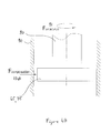
- Figures 4A and Figure 4B illustrate schematically the application of forces 134A, 134B to overcome radial unbalance forces 91 by forcing support 65, 75 against the inner side of shaft housing 90, thereby preventing surface damage arising from impacts of supports 65, 75 against the inner side of shaft housing 90.
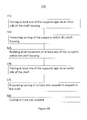
- Figure 4B illustrates method 150 operable in drive shaft system 100 comprising shaft 80 connected to motor 60 via coupling 50 and arranged to transmit a rotary movement from motor 60 to rotor 70, and supports 65, 75 arranged to position shaft 80 within shaft housing 90.
- Supports 65, 75 comprise bearings 95, 98 respectively.
- Method 150 comprises forcing at least one of the bearings in radial direction to prevent the at least one of the bearings from turning, while enabling axial movement of the at least one of the bearings.
- Method 150 comprises any of the following stages: forcing at least one of the supports (e.g. the bearings) against an inner side of the shaft housing (stage 155); preventing turning of the supports (e.g. the bearings) within the shaft housing (stage 160); enabling axial movement of at least one of the supports within the shaft housing (stage 165); forcing at least one of the supports (e.g. the bearings) against an outer side of the shaft (stage 170); preventing turning of at least one support in respect to the shaft (stage 175); and cooling at least one support (stage 180).
Landscapes
- Engineering & Computer Science (AREA)
- General Engineering & Computer Science (AREA)
- Mechanical Engineering (AREA)
- Motor Or Generator Frames (AREA)
- Support Of The Bearing (AREA)
- Mounting Of Bearings Or Others (AREA)
Priority Applications (3)
| Application Number | Priority Date | Filing Date | Title |
|---|---|---|---|
| EP10179954A EP2434171A1 (fr) | 2010-09-27 | 2010-09-27 | Système d'arbre de transmission |
| PCT/IB2011/054139 WO2012042439A1 (fr) | 2010-09-27 | 2011-09-21 | Système d'arbre d'entraînement |
| US13/823,684 US9359899B2 (en) | 2010-09-27 | 2011-09-21 | Drive shaft system |
Applications Claiming Priority (1)
| Application Number | Priority Date | Filing Date | Title |
|---|---|---|---|
| EP10179954A EP2434171A1 (fr) | 2010-09-27 | 2010-09-27 | Système d'arbre de transmission |
Publications (1)
| Publication Number | Publication Date |
|---|---|
| EP2434171A1 true EP2434171A1 (fr) | 2012-03-28 |
Family
ID=43646462
Family Applications (1)
| Application Number | Title | Priority Date | Filing Date |
|---|---|---|---|
| EP10179954A Withdrawn EP2434171A1 (fr) | 2010-09-27 | 2010-09-27 | Système d'arbre de transmission |
Country Status (3)
| Country | Link |
|---|---|
| US (1) | US9359899B2 (fr) |
| EP (1) | EP2434171A1 (fr) |
| WO (1) | WO2012042439A1 (fr) |
Citations (3)
| Publication number | Priority date | Publication date | Assignee | Title |
|---|---|---|---|---|
| US3485540A (en) * | 1968-06-20 | 1969-12-23 | Chrysler Corp | Journal mounting for rotatable shaft |
| WO2003086836A2 (fr) * | 2002-04-17 | 2003-10-23 | Robert Bosch Gmbh | Engrenage de direction sans jeu |
| WO2009047973A1 (fr) * | 2007-10-10 | 2009-04-16 | Ntn Corporation | Dispositif de support d'arbre |
Family Cites Families (5)
| Publication number | Priority date | Publication date | Assignee | Title |
|---|---|---|---|---|
| US2232473A (en) * | 1939-05-10 | 1941-02-18 | Gemmer Mfg Co | Self-adjusting antifriction bearing |
| JPS6241423A (ja) * | 1985-08-13 | 1987-02-23 | Mitsubishi Electric Corp | 軸受装置 |
| FR2795785B1 (fr) * | 1999-06-30 | 2002-06-28 | Nacam | Dispositif d'accouplement a billes de deux arbres coulissants |
| DE102005058078A1 (de) * | 2005-12-06 | 2007-06-21 | Robert Bosch Gmbh | Lagersystem für einen Elektromotor |
| JP5135338B2 (ja) | 2006-06-19 | 2013-02-06 | アイ・ディ・イー・テクノロジーズ・リミテッド | コンプレッサー用ローター |
-
2010
- 2010-09-27 EP EP10179954A patent/EP2434171A1/fr not_active Withdrawn
-
2011
- 2011-09-21 US US13/823,684 patent/US9359899B2/en active Active
- 2011-09-21 WO PCT/IB2011/054139 patent/WO2012042439A1/fr not_active Ceased
Patent Citations (3)
| Publication number | Priority date | Publication date | Assignee | Title |
|---|---|---|---|---|
| US3485540A (en) * | 1968-06-20 | 1969-12-23 | Chrysler Corp | Journal mounting for rotatable shaft |
| WO2003086836A2 (fr) * | 2002-04-17 | 2003-10-23 | Robert Bosch Gmbh | Engrenage de direction sans jeu |
| WO2009047973A1 (fr) * | 2007-10-10 | 2009-04-16 | Ntn Corporation | Dispositif de support d'arbre |
Also Published As
| Publication number | Publication date |
|---|---|
| WO2012042439A1 (fr) | 2012-04-05 |
| US20130195615A1 (en) | 2013-08-01 |
| US9359899B2 (en) | 2016-06-07 |
Similar Documents
| Publication | Publication Date | Title |
|---|---|---|
| EP1618308B1 (fr) | Pompe a vide | |
| RU2434151C2 (ru) | Устройство привода ротора вспомогательного агрегата газотурбинного двигателя, опора агрегатов для газотурбинного двигателя и газотурбинный двигатель | |
| EP2486295B1 (fr) | Système de palier auxiliaire à bague de lubrification pour système de rotor à support magnétique | |
| CA2610255C (fr) | Pompe a vide | |
| EP2572115B1 (fr) | Système de support de machine à induction | |
| EP2686577B1 (fr) | Volant d'inertie à grande vitesse | |
| EP2412080B1 (fr) | Ensemble palier | |
| CN108119542B (zh) | 着陆轴承组件和装配有这种组件的旋转机械 | |
| US9309922B2 (en) | Set of rolling bearings and corresponding rotary machine | |
| US20160025073A1 (en) | Shaft coupling device and wind power generation device | |
| US8122781B2 (en) | Generator shear gear | |
| JP6155713B2 (ja) | 風力発電装置用の一方向クラッチ及び風力発電装置 | |
| EP2434171A1 (fr) | Système d'arbre de transmission | |
| CA2683251A1 (fr) | Compresseur avec double palier d'appui exterieur | |
| US20120291625A1 (en) | Nutating swash plate ball bearing assembly | |
| US9869352B2 (en) | Clutch unit and wind power generation device | |
| EP2985485A1 (fr) | Procédé d'assemblage d'unité d'embrayage | |
| EP4068587B1 (fr) | Machine électrique rotative | |
| EP4206484B1 (fr) | Accouplement à rotule flexible à plusieurs étages, en particulier pour des entraînements réversibles | |
| CN221120671U (zh) | 一种风机防振轴承及其轴 | |
| CN116950826A (zh) | 用于全伞式水轮发电机的组合轴承装置 |
Legal Events
| Date | Code | Title | Description |
|---|---|---|---|
| PUAI | Public reference made under article 153(3) epc to a published international application that has entered the european phase |
Free format text: ORIGINAL CODE: 0009012 |
|
| AK | Designated contracting states |
Kind code of ref document: A1 Designated state(s): AL AT BE BG CH CY CZ DE DK EE ES FI FR GB GR HR HU IE IS IT LI LT LU LV MC MK MT NL NO PL PT RO SE SI SK SM TR |
|
| AX | Request for extension of the european patent |
Extension state: BA ME RS |
|
| 17P | Request for examination filed |
Effective date: 20120725 |
|
| 17Q | First examination report despatched |
Effective date: 20170720 |
|
| STAA | Information on the status of an ep patent application or granted ep patent |
Free format text: STATUS: THE APPLICATION IS DEEMED TO BE WITHDRAWN |
|
| 18D | Application deemed to be withdrawn |
Effective date: 20171201 |