EP2434186A1 - Système de tuyauterie pour des installations de traitement des industries alimentaires et des boissons - Google Patents
Système de tuyauterie pour des installations de traitement des industries alimentaires et des boissons Download PDFInfo
- Publication number
- EP2434186A1 EP2434186A1 EP20110008568 EP11008568A EP2434186A1 EP 2434186 A1 EP2434186 A1 EP 2434186A1 EP 20110008568 EP20110008568 EP 20110008568 EP 11008568 A EP11008568 A EP 11008568A EP 2434186 A1 EP2434186 A1 EP 2434186A1
- Authority
- EP
- European Patent Office
- Prior art keywords
- valve
- pipe
- connection
- hollow structure
- housing
- Prior art date
- Legal status (The legal status is an assumption and is not a legal conclusion. Google has not performed a legal analysis and makes no representation as to the accuracy of the status listed.)
- Withdrawn
Links
- 238000000034 method Methods 0.000 title claims abstract description 50
- 235000013361 beverage Nutrition 0.000 title description 3
- 235000013305 food Nutrition 0.000 title description 3
- 238000004140 cleaning Methods 0.000 claims description 9
- 230000002093 peripheral effect Effects 0.000 claims description 6
- 238000004220 aggregation Methods 0.000 claims description 5
- 230000002776 aggregation Effects 0.000 claims description 5
- 230000001419 dependent effect Effects 0.000 claims description 5
- 239000012530 fluid Substances 0.000 claims description 5
- 241000196324 Embryophyta Species 0.000 description 11
- 238000007789 sealing Methods 0.000 description 6
- 239000011159 matrix material Substances 0.000 description 4
- 230000000630 rising effect Effects 0.000 description 4
- 239000012459 cleaning agent Substances 0.000 description 3
- 238000011010 flushing procedure Methods 0.000 description 3
- 230000015572 biosynthetic process Effects 0.000 description 2
- 238000005520 cutting process Methods 0.000 description 2
- 238000013461 design Methods 0.000 description 2
- 239000007788 liquid Substances 0.000 description 2
- 239000000463 material Substances 0.000 description 2
- 239000000203 mixture Substances 0.000 description 2
- 238000012986 modification Methods 0.000 description 2
- 230000004048 modification Effects 0.000 description 2
- 238000012546 transfer Methods 0.000 description 2
- 244000290594 Ficus sycomorus Species 0.000 description 1
- 244000124853 Perilla frutescens Species 0.000 description 1
- 235000004348 Perilla frutescens Nutrition 0.000 description 1
- 240000004808 Saccharomyces cerevisiae Species 0.000 description 1
- 239000003637 basic solution Substances 0.000 description 1
- 235000013405 beer Nutrition 0.000 description 1
- 238000004891 communication Methods 0.000 description 1
- 150000001875 compounds Chemical class 0.000 description 1
- 238000011109 contamination Methods 0.000 description 1
- 238000009826 distribution Methods 0.000 description 1
- 238000000855 fermentation Methods 0.000 description 1
- 230000004151 fermentation Effects 0.000 description 1
- 235000011194 food seasoning agent Nutrition 0.000 description 1
- 230000005484 gravity Effects 0.000 description 1
- 238000012423 maintenance Methods 0.000 description 1
- 238000004519 manufacturing process Methods 0.000 description 1
- 230000002906 microbiologic effect Effects 0.000 description 1
- 238000002156 mixing Methods 0.000 description 1
- 238000012544 monitoring process Methods 0.000 description 1
- 238000012545 processing Methods 0.000 description 1
- 238000000926 separation method Methods 0.000 description 1
- 238000007493 shaping process Methods 0.000 description 1
- 239000000243 solution Substances 0.000 description 1
- 238000003860 storage Methods 0.000 description 1
- 238000012549 training Methods 0.000 description 1
- 238000003466 welding Methods 0.000 description 1
Images



Classifications
-
- F—MECHANICAL ENGINEERING; LIGHTING; HEATING; WEAPONS; BLASTING
- F16—ENGINEERING ELEMENTS AND UNITS; GENERAL MEASURES FOR PRODUCING AND MAINTAINING EFFECTIVE FUNCTIONING OF MACHINES OR INSTALLATIONS; THERMAL INSULATION IN GENERAL
- F16K—VALVES; TAPS; COCKS; ACTUATING-FLOATS; DEVICES FOR VENTING OR AERATING
- F16K1/00—Lift valves or globe valves, i.e. cut-off apparatus with closure members having at least a component of their opening and closing motion perpendicular to the closing faces
- F16K1/32—Details
- F16K1/34—Cutting-off parts, e.g. valve members, seats
- F16K1/44—Details of seats or valve members of double-seat valves
- F16K1/443—Details of seats or valve members of double-seat valves the seats being in series
- F16K1/446—Details of seats or valve members of double-seat valves the seats being in series with additional cleaning or venting means between the two seats
-
- B—PERFORMING OPERATIONS; TRANSPORTING
- B67—OPENING, CLOSING OR CLEANING BOTTLES, JARS OR SIMILAR CONTAINERS; LIQUID HANDLING
- B67D—DISPENSING, DELIVERING OR TRANSFERRING LIQUIDS, NOT OTHERWISE PROVIDED FOR
- B67D7/00—Apparatus or devices for transferring liquids from bulk storage containers or reservoirs into vehicles or into portable containers, e.g. for retail sale purposes
- B67D7/06—Details or accessories
- B67D7/36—Arrangements of flow- or pressure-control valves
-
- B—PERFORMING OPERATIONS; TRANSPORTING
- B67—OPENING, CLOSING OR CLEANING BOTTLES, JARS OR SIMILAR CONTAINERS; LIQUID HANDLING
- B67D—DISPENSING, DELIVERING OR TRANSFERRING LIQUIDS, NOT OTHERWISE PROVIDED FOR
- B67D7/00—Apparatus or devices for transferring liquids from bulk storage containers or reservoirs into vehicles or into portable containers, e.g. for retail sale purposes
- B67D7/06—Details or accessories
- B67D7/78—Arrangements of storage tanks, reservoirs or pipe-lines
-
- B—PERFORMING OPERATIONS; TRANSPORTING
- B67—OPENING, CLOSING OR CLEANING BOTTLES, JARS OR SIMILAR CONTAINERS; LIQUID HANDLING
- B67D—DISPENSING, DELIVERING OR TRANSFERRING LIQUIDS, NOT OTHERWISE PROVIDED FOR
- B67D2210/00—Indexing scheme relating to aspects and details of apparatus or devices for dispensing beverages on draught or for controlling flow of liquids under gravity from storage containers for dispensing purposes
- B67D2210/00028—Constructional details
- B67D2210/00047—Piping
- B67D2210/0006—Manifolds
-
- Y—GENERAL TAGGING OF NEW TECHNOLOGICAL DEVELOPMENTS; GENERAL TAGGING OF CROSS-SECTIONAL TECHNOLOGIES SPANNING OVER SEVERAL SECTIONS OF THE IPC; TECHNICAL SUBJECTS COVERED BY FORMER USPC CROSS-REFERENCE ART COLLECTIONS [XRACs] AND DIGESTS
- Y10—TECHNICAL SUBJECTS COVERED BY FORMER USPC
- Y10T—TECHNICAL SUBJECTS COVERED BY FORMER US CLASSIFICATION
- Y10T137/00—Fluid handling
- Y10T137/4238—With cleaner, lubrication added to fluid or liquid sealing at valve interface
- Y10T137/4245—Cleaning or steam sterilizing
-
- Y—GENERAL TAGGING OF NEW TECHNOLOGICAL DEVELOPMENTS; GENERAL TAGGING OF CROSS-SECTIONAL TECHNOLOGIES SPANNING OVER SEVERAL SECTIONS OF THE IPC; TECHNICAL SUBJECTS COVERED BY FORMER USPC CROSS-REFERENCE ART COLLECTIONS [XRACs] AND DIGESTS
- Y10—TECHNICAL SUBJECTS COVERED BY FORMER USPC
- Y10T—TECHNICAL SUBJECTS COVERED BY FORMER US CLASSIFICATION
- Y10T137/00—Fluid handling
- Y10T137/4238—With cleaner, lubrication added to fluid or liquid sealing at valve interface
- Y10T137/4245—Cleaning or steam sterilizing
- Y10T137/4259—With separate material addition
-
- Y—GENERAL TAGGING OF NEW TECHNOLOGICAL DEVELOPMENTS; GENERAL TAGGING OF CROSS-SECTIONAL TECHNOLOGIES SPANNING OVER SEVERAL SECTIONS OF THE IPC; TECHNICAL SUBJECTS COVERED BY FORMER USPC CROSS-REFERENCE ART COLLECTIONS [XRACs] AND DIGESTS
- Y10—TECHNICAL SUBJECTS COVERED BY FORMER USPC
- Y10T—TECHNICAL SUBJECTS COVERED BY FORMER US CLASSIFICATION
- Y10T137/00—Fluid handling
- Y10T137/8593—Systems
- Y10T137/87249—Multiple inlet with multiple outlet
-
- Y—GENERAL TAGGING OF NEW TECHNOLOGICAL DEVELOPMENTS; GENERAL TAGGING OF CROSS-SECTIONAL TECHNOLOGIES SPANNING OVER SEVERAL SECTIONS OF THE IPC; TECHNICAL SUBJECTS COVERED BY FORMER USPC CROSS-REFERENCE ART COLLECTIONS [XRACs] AND DIGESTS
- Y10—TECHNICAL SUBJECTS COVERED BY FORMER USPC
- Y10T—TECHNICAL SUBJECTS COVERED BY FORMER US CLASSIFICATION
- Y10T137/00—Fluid handling
- Y10T137/8593—Systems
- Y10T137/877—With flow control means for branched passages
-
- Y—GENERAL TAGGING OF NEW TECHNOLOGICAL DEVELOPMENTS; GENERAL TAGGING OF CROSS-SECTIONAL TECHNOLOGIES SPANNING OVER SEVERAL SECTIONS OF THE IPC; TECHNICAL SUBJECTS COVERED BY FORMER USPC CROSS-REFERENCE ART COLLECTIONS [XRACs] AND DIGESTS
- Y10—TECHNICAL SUBJECTS COVERED BY FORMER USPC
- Y10T—TECHNICAL SUBJECTS COVERED BY FORMER US CLASSIFICATION
- Y10T137/00—Fluid handling
- Y10T137/8593—Systems
- Y10T137/87917—Flow path with serial valves and/or closures
- Y10T137/88022—One valve head provides seat for other head
- Y10T137/8803—Also carries head of other valve
Definitions
- the invention relates to a device for piping of process equipment of the food and beverage industry according to the preamble of claim 1, wherein these devices are particularly applicable where the product handling and product transfer process facilities serving high microbiological quality requirements and demands for best cleaning ability in the flow (so-called CIP capability) and where a compact and flexible design of the plant is required.
- CIP capability the product handling and product transfer process facilities serving high microbiological quality requirements and demands for best cleaning ability in the flow
- the application also includes areas of pharmacy and biotechnology in particular.
- FIG. 1 of the document DE 101 08 259 C1 shown and described (Sections 003 to 020).
- This example describes a piping system of a brewery, which consists of five fermentation tanks. Their number is readily expandable and the plant may typically additionally include process units connected to the piping system.
- the supply lines from the various tanks and process units are fed to a valve block (referred to as VB) and distributed from there, for example, to associated filling machines and connected.
- VB valve block
- the connection points at which incompatible media can face each other are equipped with so-called mix-proof valves, typically double-seated valves.
- valve block can be made compact, even in process plants, where the tanks and process units are arbitrarily positioned. In addition to reduced costs and reduced space requirements, this simplifies the cleaning, maintenance and monitoring of the process plant.
- Another piping system is for example from the DE 101 08 259 C1
- this is limited to a piping arrangement in which a so-called valve manifold tree is associated with a tank of a tank storage system, directly from the tank bottom opens and a rising from bottom to top, usually has a vertical course.
- the process lines and function valves are mounted directly under the respective tank outlet.
- This piping system has been proven in practice in the meantime; it is in the company publication Tuchenhagen Brewery Systems, ECO-Matrix ®, 223d-10/06, described in more detail under the name ECO-Matrix ®, and in particular under the aspect of cost and the influence on the product quality.
- the function valves can either be attached to the side of the tank outlet tree, the so-called. Ventilverteilerbaum, or perpendicular to the bottom flange of the tank.
- This piping technique significantly minimizes the formation of contamination and its subsequent distribution in the process system.
- the piping system, separated from the tank, allows for complete product evacuation and tank-independent cleaning.
- the instrumentation costs are reduced in this newer piping technique, while the process for a nearly lossless production operation can be optimized.
- the valve manifold is designed as an elongated hollow body, it is oriented substantially vertically and it has connection openings for connection its interior with piping of a pipe system, which are guided laterally on the valve manifold.
- a mixing-resistant valve configured in its seating area is arranged, which switches this connection in the immediate vicinity of the hollow body.
- a so-called double-seat valve with two closing elements movable relative to one another or a so-called double-sealing valve with two seat seals spaced apart on a single closing element in the stroke direction or a so-called leak-proof disk valve can be used as a mix-proof valve.
- a leakage cavity connected to the vicinity of the double seat valve via at least one communication path.
- Double-seat valve As a preferred mix-safe valve found in the piping systems in question so far the vorg. Double-seat valve use, the latter having concentrically arranged one another valve rods for the closing members, which are on one side through the valve housing and led out of this to a drive.
- a double seat valve with a related Sch thoroughlyglied- and valve rod configuration is already out of the US 4 436 106 A known.
- the arranged between the two closing elements leakage cavity is drained via a leakage drain between the valve rod of the independently driven first closing member and a valve rod surrounding the hollow rod of the dependent driven second closing member.
- the second closing member is designed as a seat plate in the form of a conical closing sleeve which carries at its end facing the first closing member an axial seat seal, which cooperates with a valve seat on the valve housing.
- the first closure member is also formed as a seat plate, which cooperates with a conical valve seat.
- One in the DE 10 2005 051 467 A1 described piping arrangement is based on a piping according to DE 101 08 259 C1 in this system at the terminals of the hollow body in each case a mix-safe valve, wherein the first closing member is driven independently and comes at its opening movement formed as a seat plate second closing member sealingly to the plant and this also transferred to the open position.
- the second closing member has, at its end facing the first closing member, a second seat seal, which cooperates with a second seating face adjoining a cylindrical first seating face.
- the first closing element designed as a slide piston has a radially acting first seat seal which sealingly engages in the first seating surface in the closed position of the valve.
- the valve rods for the closing elements are arranged concentrically with one another and are guided on one side through the valve housing and out of this.
- the valve is the DE 10 2005 051 467 A1 arranged in an oblique arrangement on the hollow body and it has, in addition to the radial sealing means on the first closing member and the axial sealing means on the second closing member, a so-called. Center seal, which is arranged in the open position of the double seat valve between the two closing members and effective on the second closing member.
- the leakage cavity of the valve has a circumferential wall extending from a connection-side inlet to an outlet-side leakage outlet opening spaced from the inlet, which has a gradient on the gravity side toward the leakage outlet opening.
- the purpose of this measure is an automatic emptying of the leakage cavity of accumulating there leakage liquid.
- the known manifold arrangement according to the DE 10 2005 051 467 A1 is, as well as the piping system after the DE 101 08 259 C1 , Limited to an arrangement in which an upper end of the hollow body (valve manifold) opens directly or via another valve in a tank bottom of a tank disposed above.
- the object of the invention is to provide a device for piping the gattungsgemä- ⁇ en type, which meets high demands on the quality of the treated fluid product in high reliability, the total, including the mix-safe valves, simple, flexible and inexpensive is constructed and in all occurring in practice arrangement variants of the valve manifold tree in relation to the associated process unit or tank of the process plant in each valve manifold tree largely the same technological conditions and state variables as in the process unit or tank maps.
- the essence of the invention consists in that the fluid products to be supplied or discharged from the pipe system flow through the hollow structures delimited by the valve manifold on the way via connection openings and that the respective fluid in this hollow structure is in close proximity to its boundary from the associated (n) connection opening (s) zoom in and on the hollow structure passing piping of the pipe system by a mix-safe valve optional, switchable and mix safe separation.
- the respective valve manifold opens directly into the lower tank bottom of a respectively assigned tank of the process plant (first arrangement variant) or / and the respective valve manifold is connected via an associated pipe connection with an associated process unit or tank of the process plant and the pipe connection opens into the tank or process unit side End of the valve manifold tree (second arrangement variant). This makes the piping systems for the most diverse applications extremely easy.
- An advantageous embodiment provides that in the first directional variant, in which the valve manifold tree ascends from bottom to top, usually a vertical course, the first and the second group of pipes in each row-like arrangement with each other, on opposite sides of the hollow structure , in each other and to the longitudinal axis of the hollow structure are arranged in parallel planes.
- Such piping is extremely compact, space-saving and clear.
- the hollow structure allows a very simple connection of the mix-proof valve, if it is formed in the peripheral area of its connection opening as an annular housing which receives the two seats and serves to connect the valve housing.
- the execution of the hollow structure is particularly simple if it, as is still provided, is designed as a cylindrical tube.
- the hollow structure can be completely emptied and cleaned properly, if its the lower end remote from the respective tank or the respective pipe connection brought from the process unit or tank is connected to a third pipe system.
- the device becomes particularly clear and simple if, according to a further proposal, the pipelines are each designed as continuous pipelines (filling, emptying, pipe cleaning) assigned to all pipe connections in the same function.
- Simple and clear pipe guides arise in the context of the piping system, if the valve manifolds have a series or matrix-shaped arrangement.
- the hollow structure is composed in each case of an aggregation of individual structural sections which are fluidly interconnected in the direction of the longitudinal axis of the hollow structure and each have at least one connection opening.
- These housing parts may be either discrete, separate parts that are joined to the hollow structure in its entirety, or a one-piece, in which the individual housing parts are materially interconnected.
- Embodiments are, according to another proposal, the sections of the building in the form of housing parts of different sizes, so that at these housing parts, if necessary, as is also provided, at least one connection opening can be performed, which is dependent on the size of the respective associated housing part passage cross-section having. Connection openings with different sized passage cross sections on a housing part are also provided. Due to this design variety, the hollow structure in all its areas through which it flows can be adapted to the fluidic requirements of the connected pipelines of different nominal widths.
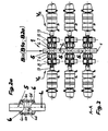
- a device 1 for piping process plants consists, for example, of three valve manifolds B1, B2 and B3, in the most general case of B1 to Bn valve manifolds, which are preferably arranged in rows and in alignment with each other.
- Each valve manifold tree B1, B2, B3 (Bi) is in the form of an elongate hollow structure B1a, B2a, B3a (in the most general case B1a to Bna; Bia), preferably in the form of a cylindrical tube or an aggregation of individual structural sections 5 (see FIG. FIG. 2 ) executed, which has a rising from bottom to top, usually a vertical course (first direction variant).
- the illustrated device 1 further shows a first pipe system 2, which consists of a first group of pipes 2.1, 2.2, 2.3 (in the most general case from 2.1 to 2.i to 2.n pipes), and a second pipe system 3, which consists of a second Group pipelines 3.1, 3.2, 3.3 (in the most general case from 3.1 to 3.i to 3.n piping) consists.
- a third pipe system 4 (for example, for cleaning) may be connected, if this place or access should not be available for other precautions.
- the first group of pipes 2.1, 2.2, 2.3 and the second group of pipes 3.1, 3.2, 3.3 are each arranged in a row with each other and, with respect to the front two Ventilverteilerbäume B1 and B2, on opposite sides of the hollow structure B1a, B2a, in two parallel to each other and to the longitudinal axis of the hollow structure arranged parallel planes and past this (two-sided arrangement of mix safe double seat valves V R ).
- the third hollow structure B3a is located, for example, directly in front of a vertical wall, so that only the first pipe system 2 is to be guided past it and to be connected (one-sided arrangement of the mix-proof double-seat valves V R ).
- FIG. 7 A perspective view of the rear valve manifold tree B3 substantially corresponding arrangement shows FIG. 7 .
- the hollow structure B1a, B2a, B3a has connection openings 6a (FIG. Figures 2 and 2a ) for connecting its interior to each of the pipes 2.1, 2.2, ..., 2.i, ..., 2.n and 3.1, 3.2, ..., 3.1, ..., 3.n and possibly 4
- the double-seated valve V R designed to be mixproof is arranged, which switches this connection in the immediate vicinity of the hollow structure B1 a, B2a, B3a.
- the respective valve manifold B1 to B3 (in the most general case B1 to Bi to Bn) opens either directly in the lower tank bottom T1a to T3a (in the most general case T1a to Tia to Tna) of a respectively assigned tank T1 to T3 (tank T;
- the most common case is T1 to Ti to Tn) of the process plant (first arrangement variant) or it is connected via an associated pipe connection R (R1 to R3, in the most general case R1 to Ri to Rn) with an associated process unit P (P1, P2, in the most general case P1 to Pi to Pn) or tank T1 (tank T, in the most general case T1 to Ti to Tn) of the process plant and the pipe joint R (R1 to R3 (in the most general case R1 to Ri to Rn) opens into the upper end of the valve manifold B1 to B3 (B1 to Bi to Bn) (second arrangement variant)
- the two aforementioned basic arrangement variants can also occur in a single device 1 (mix
- the upper end of the first valve manifold B1 is connected to a first process unit P1 via a first pipe connection R1
- the second valve manifold B2 is connected to a first tank T1 via a second pipe connection R2
- the third valve manifold B3 is connected via a third pipe connection R3 connected to a second process unit P2.
- the process units P or the tanks T can assume any arrangement and positioning in the second arrangement variant, while the valve manifolds B1 to Bn are preferably arranged in rows or in a matrix.
- the illustrated pipe joint R1 to R3 may be in the region of their connected to the valve manifold tree B1 to B3 (B1 to Bn) end portion in each case a vertical or any inclined end portion.
- the inclined end portion which extends horizontally in the limiting case, with a corresponding pipe bend connection to the tank or process unit end of the respective valve manifold tree B1 to B3 (B1 to Bn).
- valve manifolds Bi can, as will be explained in detail later, also be arranged horizontally (second direction variant).
- first direction variant For the connection of the respective horizontally arranged valve manifold tree Bi with the associated tank Ti or process unit Pi, the above statements apply mutatis mutandis.
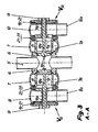
- FIG. 2 shows that the hollow structure B1a, B2a (in the most general case Bia) can be composed, for example, of three identical structural sections 5, wherein each structural section 5 (FIG. FIG. 2a ) is formed in the peripheral region of its connection openings 6a as an annular housing 6, each receiving on the inside a first seat 6b, a second seat 6c and a cylindrical recess 6d.
- the annular housing 6 is adjoined, in each case transversely to the longitudinal direction (longitudinal axis L) of the structural section 5, on both sides by a first valve housing 7 (see also FIG FIG.
- the valve housing 7 is part of the mixproof double-seat valve V R. Connected to the valve housing 7, seen in the longitudinal direction of the double-sighted valve V R , laterally a leakage and drain housing 8 ( Figures 3 . 2 ) with a drain connection 8a and a non-descript drive, the latter being connected to the leakage and drain housing 8 via a lantern housing 9.
- the double seat valve V R is formed with two serially arranged closing members 10, 11, which in the closed position of the valve prevent the overflow of fluids from the hollow structure Bia or from the building section 5 into the valve housing 7.
- the closure members 10, 11 define both in the closed and in the open position a leakage cavity 14, the at least one connection path having the environment of the double seat valve V R.
- the interior of the leakage and drain housing 8 and its drain port 8a are part of this connection path.
- the first closing member 10 is connected to a first valve rod 10a and the second closing member 11 is connected to a second valve rod 11a, which are arranged concentrically in one another and on one side through the first valve housing 7 and from this via the leakage and drain housing 8 to the drive led out.
- the guidance and sealing of the second closing member 11 in a region 21-25 between the housings 7, 8 and the second valve rod 11a in a region 16-21 between the housings 8, 9 is not described in detail.
- FIGS. 4 to 4c An advantageous embodiment of the building section 5, its two annular housing 6 and the respectively adjoining valve housing 7 show the FIGS. 4 to 4c ,
- the structural section 5 and the two annular housings 6 are made in one piece, and the first valve housing 7 in each case surrounds the annular housing 6 radially on the outside and is connected to it in a material-locking manner, preferably by welding.
- Designated connection opening 6a forms with its peripheral boundary, the cylindrical first seat surface 6b for the first closing member 10 from.
- a flushing port 28 may be provided.
- the pipe connections 7a are, as already described above, tangentially connected to the first valve housing 7.
- the first valve housing 7 has at its the leak and drain housing 8 facing the end in each case a first clamping flange 7b, via which it is releasably connected to the leakage and drain housing 8 via a so-called. Clamping ring.
- FIGS. 5 to 5c show one opposite the FIGS. 4 to 4c modified housing configuration.
- the difference is, in particular, that the two first valve housings 7 are now no longer of the same size, but that a second valve housing 7 * is smaller than the first valve housing 7 and that the first valve housing 7 associated pipe connections 7a and the second valve housing. 7 * assigned modified pipe connection 7a * each center out of the respective valve housing 7, 7 *.
- the modified pipe connection 7a * is provided with a second clamping flange 7b *, with which it is connected to a leakage and drain housing 8 of corresponding nominal diameter, not shown, by means of a further clamping ring.
- FIG. 3 shows further details of the mixproof double seat valve V R. From the valve manifold Bi only one structural section 5 is taken out, wherein the valve manifold Bi is connected via a pipe connection with a process unit or a tank. Based on the features of the double-seat valve V R already described above, it should be added that the first closing member 10 is driven independently and comes into abutment with its opening movement on the second closing member 11 designed as a seat plate and likewise transfers this into the open position.
- the second closing member 11 is formed as a hollow rod, preferably as a cylindrical closing sleeve or tubular and at least approximately cylindrical inside and outside, which has on its the first closing member 10 facing end face an axially acting second seat seal which adjacent to the cylindrical first seat 6b second seat 6c cooperates ( FIG. 2a ).
- the trained as a spool first closing member 10 has a radially acting first seat seal, which is in the closed position of the double seat valve V R in the first seat 6b sealingly receiving.
- the cylindrical first seat surface 6b is formed in the peripheral wall defining the connection opening 6a.
- the second closing member 11 has at its the second seat seal receiving end portion on the inside a cylindrical receiving bore formed with the same diameter with the cylindrical first seat surface 6b. In the closed position of the second closing member 11, the receiving bore and the first seat surface 6b are flush with each other, so that leakage-free switching with only two seat seals is provided.
- the formed as a hollow rod second closing member 11 is formed on its outer circumferential surface cylindrical, and it opens into the leakage and drain housing 8 ( FIG. 3 ), which adjoins the latter with a clamping flange on the side facing away from the annular housing 6 of the valve housing 7.
- the detachable connection takes over a clamping ring.
- the outer circumferential surface is guided and sealed in the connection region between the valve housing 7 and the leakage and drain housing 8.
- the second closing member 11 is in the region of the interior of the leakage and drain housing 8 on the smaller diameter second valve rod 11 a via ( FIG. 3 ), and there is provided a fluid-permeable connection between the interior of the second closing member 11 and the interior of the hollow bar-shaped second valve rod 11a via at least one substantially radially oriented traverse.
- the valve rods 10a, 11a are on the side facing away from the valve housing 7 of the leakage and drain housing 8 through the latter and led out of this, where they pass through the lamp housing 9 axially and are guided to a drive of the double seat valve V R , not shown.
- the leakage cavity 14 is connected via a limited by an inner circumferential surface of the second closing member 11 drain hole with the interior of the leakage and drain housing 8, which opens into the drain port 8a.
- the leakage and drain housing 8 is closed at the lantern housing side by a cover part 16, which is sealed on the housing side by means of a further housing seal 21 and valve rod side by means of a rod seal.
- the illustrated horizontal arrangement of the double-seat valve V R represents a preferred arrangement, which is possible because even in this position by the above-described embodiment of the double seat valve V R, a self-emptying of the leakage cavity 14 without puddling is possible.
- the double seat valves V R provided on each hollow structure Bia, wherein, based on the arrangement position, the longitudinal axis of the concentrically arranged closing members 10, 11 and their valve rods 10a, 11a horizontally or, seen from the closing members 10, 11 from , Down to an angle to the horizontal sloping, and wherein a running at the lowest point surface line of the inner circumferential surface of the second closing member 11 also at least horizontally or at an angle to the horizontal sloping.
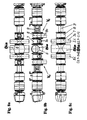
- the hollow structure B1a to Bna can each also be composed of an aggregation of a number of individual structural sections 5 (see this FIGS. 1 . 2 . 2a . 6 ), which are fluidly interconnected in the direction of the longitudinal axis L of the valve manifold tree B1 to Bn and each have at least on one side the connection opening 6a.
- the structural sections 5 can in the form of housing parts B1a.1 to B6a.1 and B1a.2 to B6a.2 (s. FIG.
- connection opening 6 in the most general case Bia.1 to Bia.m with housing parts 1 to m of the hollow structure Bia) be designed to be different in size, in which case, for example, the respective connection opening 6a may have a dependent on the size of the respective associated structure section 5 passage cross-section. If there is more than one connection opening 6a on the respective building section 5, differently sized passage cross sections of the connection openings 6a are also carried out if necessary.
- FIG. 6 shows that the hollow structure B1a to B6a in an existing of six valve manifolds B1 to B6 device (in the most general case Bia) may be composed of two sections 5 example.
- the ring housing 6 see FIG. 2a
- the pipe connection 7a on the valve housing 7, with respect to the arrangement position opens tangentially with its lowermost inner surface line at the lowest point of the interior of the valve housing 7.
- This pipe 3.2 * is consistently designed with an unobstructed, circular shape having flow cross-section, making them suitable for a newt is consistent; it is guided past the associated valve housing 7 of the mixproof double-seat valve V R and fluidly connected to the latter.
- each of the pipes 2.1 to 2.n of the first group of pipes of the first pipe system 2 and each of the pipes 3.1 to 3.n of the second group of pipes of the second pipe system 3 and possibly also the third pipe system 4 can be made piggable in the manner described above .
- the valve housing 7 of a further double-seat valve V R is arranged only on the left side, to whose pipe connection 7 a the first pipe 3.1 from the second group of pipes of the second pipe system 3 is brought.
- the pipe connection 7a on the valve housing 7, with respect to the arrangement position opens tangentially with its lowermost inner surface line at the lowest point of the interior of the valve housing 7.
- the respective valve housing 7 is part of the mixproof double-seat valve V R. Connected to the valve housing 7, seen in the longitudinal direction of the double sight valve V R , laterally the leakage and drain housing 8 with the drain port 8a and a unspecified drive to, the latter is connected to the leakage and drain housing 8 via the lamp housing 9.
- each one-sided arrangement of three superimposed mix-proof double seat valves V R according to the in FIG. 1 already described piping (there the rear valve manifold B3) shows FIG. 7 ,
- FIG. 6 With regard to the further embodiment of this aggregation, reference is made to the explanations FIG. 6 directed.
- FIGS. 8a to 8c An advantageous embodiment of the structural section 5, from which the hollow structure B1 a (Bia) of the valve manifold tree B1 (Bi) is composed, with both sides arranged and aligned leak-proof double seat valves V R , as he preferably in the horizontally arranged valve manifold tree B1 (Bi) for use comes (second direction variant), show the FIGS. 8a to 8c .
- the pipe connection 7a is arranged tangentially in the lower region of the valve housing 7.
- the hollow structure B1a (Bia), which in each case has the shape of a circular cross-section pipe section, opens in such a way in the upper region of the building section 5 that by avoiding a swamp-forming space in the building section 5 below the hollow structure B1a (Bia) shaping measures a complete flow of liquid from the latter is ensured in the valve housing 8 connected on both sides.
- the valve distributor tree Bi extends transversely, as a rule horizontally, and the first and possibly the second group of pipes 2.1 to 2.n and 3.1 to 3.n are arranged side by side in mutually parallel planes and on one side or on opposite sides Side of the hollow structure Bia and in its longitudinal axis L crossing planes passed this.
- a piping is used when the height below the tank Ti or the process unit Pi limited and thereby the arrangement of a valve manifold Bi with a rising from bottom to top, usually with a vertical course, is not possible and if at the same time the entire relevant piping below the outlet of the tank Ti or the process unit Pi is to be arranged.
Landscapes
- Engineering & Computer Science (AREA)
- Mechanical Engineering (AREA)
- General Engineering & Computer Science (AREA)
- Valve Housings (AREA)
- Pipeline Systems (AREA)
- Multiple-Way Valves (AREA)
- General Preparation And Processing Of Foods (AREA)
- Tea And Coffee (AREA)
- Lift Valve (AREA)
Applications Claiming Priority (4)
| Application Number | Priority Date | Filing Date | Title |
|---|---|---|---|
| DE102008026149A DE102008026149A1 (de) | 2008-05-30 | 2008-05-30 | Verrohrungssystem für Prozessanlagen der Nahrungsmittel- und Getränkeindustrie |
| DE102008035940 | 2008-07-31 | ||
| DE102008051819A DE102008051819A1 (de) | 2008-07-31 | 2008-10-15 | Vorrichtung zur Verrohrung von Prozessanlagen der Nahrungsmittel- und Getränkeindustrie und Verfahren zum Betrieb einer Vorrichtung |
| EP09757208A EP2281132B1 (fr) | 2008-05-30 | 2009-05-27 | Système de tuyauterie pour des installations de traitement des industries alimentaires et des boissons |
Related Parent Applications (1)
| Application Number | Title | Priority Date | Filing Date |
|---|---|---|---|
| EP09757208.5 Division | 2009-05-27 |
Publications (1)
| Publication Number | Publication Date |
|---|---|
| EP2434186A1 true EP2434186A1 (fr) | 2012-03-28 |
Family
ID=43414265
Family Applications (2)
| Application Number | Title | Priority Date | Filing Date |
|---|---|---|---|
| EP09757208A Active EP2281132B1 (fr) | 2008-05-30 | 2009-05-27 | Système de tuyauterie pour des installations de traitement des industries alimentaires et des boissons |
| EP20110008568 Withdrawn EP2434186A1 (fr) | 2008-05-30 | 2009-05-27 | Système de tuyauterie pour des installations de traitement des industries alimentaires et des boissons |
Family Applications Before (1)
| Application Number | Title | Priority Date | Filing Date |
|---|---|---|---|
| EP09757208A Active EP2281132B1 (fr) | 2008-05-30 | 2009-05-27 | Système de tuyauterie pour des installations de traitement des industries alimentaires et des boissons |
Country Status (9)
| Country | Link |
|---|---|
| US (1) | US8596298B2 (fr) |
| EP (2) | EP2281132B1 (fr) |
| AT (1) | ATE551563T1 (fr) |
| CA (1) | CA2726068C (fr) |
| DK (1) | DK2281132T3 (fr) |
| ES (1) | ES2384148T3 (fr) |
| PL (1) | PL2281132T3 (fr) |
| PT (1) | PT2281132E (fr) |
| WO (1) | WO2009146825A1 (fr) |
Families Citing this family (4)
| Publication number | Priority date | Publication date | Assignee | Title |
|---|---|---|---|---|
| US9644795B2 (en) * | 2012-12-18 | 2017-05-09 | Baker Hughes Incorporated | Fracturing fluid process plant and method thereof |
| DK2816266T3 (en) | 2013-06-21 | 2018-07-30 | Alfa Laval Corp Ab | DOUBLE SEAT VALVE |
| JP6751552B2 (ja) * | 2015-06-04 | 2020-09-09 | サーパス工業株式会社 | 流体機器 |
| EP4093997B1 (fr) * | 2020-01-24 | 2025-01-15 | GEA Tuchenhagen GmbH | Soupape et procédé de nettoyage |
Citations (3)
| Publication number | Priority date | Publication date | Assignee | Title |
|---|---|---|---|---|
| US4436106A (en) | 1977-01-29 | 1984-03-13 | Otto Tuchenhagen Gmbh & Co. Kg | Pipeline switch with leakage control and cleanable leakage cavity |
| DE10108259C1 (de) | 2001-02-21 | 2002-01-03 | Tuchenhagen Gmbh | Verfahren und Vorrichtung zum Betrieb von Tanklagersystemen im festverrohrten Verbund mit Rohrsystemen für Flüssigkeiten |
| DE102005051467A1 (de) | 2005-10-24 | 2007-04-26 | Südmo Holding GmbH | Rohrverzweigungsanordnung |
Family Cites Families (17)
| Publication number | Priority date | Publication date | Assignee | Title |
|---|---|---|---|---|
| DE900763C (de) | 1952-04-27 | 1954-01-04 | Paul Kahle Rohrleitungsbau G M | Vorrichtung zum zwangslaeufigen Dehnungsausgleich an Rohrleitungen u. dgl. |
| DE2229987A1 (de) | 1972-06-20 | 1974-01-10 | Eltro Gmbh | Einrichtung zur ermittlung der achsbelastung an fahrzeugen |
| DE2847038C3 (de) | 1978-10-28 | 1984-06-28 | Leonhard Schleicher Südmo-Armaturenfabrik GmbH, 7081 Riesbürg | Klappenartiges Absperrelement mit Leckagesicherung in Rohrleitungssystemen |
| DE2948534A1 (de) | 1979-12-01 | 1981-07-16 | Leonhard Schleicher Südmo-Armaturenfabrik GmbH, 7081 Riesbürg | Absperrklappe mit leckagesicherung in rohrleitungssystemen |
| DE3042895A1 (de) | 1979-12-01 | 1982-05-19 | Leonhard Schleicher Südmo-Armaturenfabrik GmbH, 7081 Riesbürg | Absperrklappe mit leckagesicherung in rohleitungssystemen |
| EP0625249B1 (fr) | 1992-02-08 | 1996-11-20 | OTTO TUCHENHAGEN GmbH & Co. KG | Soupape a double siege |
| US5275201A (en) * | 1992-07-23 | 1994-01-04 | Tri-Clover, Inc. | Manifold valve assembly with removable valve seat |
| US5232023A (en) * | 1992-12-22 | 1993-08-03 | Tri-Clover, Inc. | Manifold valve assemblies |
| US5390694A (en) * | 1993-10-13 | 1995-02-21 | Tri-Clover, Inc. | Vat bottom fill CIP system |
| US5441079A (en) * | 1994-04-22 | 1995-08-15 | Tri-Clover, Inc. | Manifold valve assemblies |
| WO1998041786A1 (fr) * | 1997-03-18 | 1998-09-24 | Tuchenhagen Gmbh | Soupape a double siege nettoyable |
| DE19722615A1 (de) | 1997-05-30 | 1998-12-03 | Lavrids Knudsen Maskinfabrik A | Leckagefrei schaltendes Doppelsitzventil |
| DE29821813U1 (de) | 1998-12-07 | 1999-02-04 | Anton Steinecker Maschinenfabrik GmbH, 85356 Freising | Umschaltpaneel |
| US6136362A (en) * | 1998-12-10 | 2000-10-24 | Alfa Laval Flow Inc. | High temperature/short time pasteurization system and method of cleaning |
| DK1218659T3 (da) | 1999-10-07 | 2004-10-04 | Tuchenhagen Gmbh | Anordning til lösbar forbindelse af rör, der er udsat for varmeudvidelser |
| DE102006059556B3 (de) | 2006-12-16 | 2007-10-31 | Tuchenhagen Gmbh | Anordnung und Verfahren zur automatischen Probenahme in einem Tanklagersystem im Verbund mit einem Rohrsystem zur Zuführung von Reinigungsfluiden |
| DE102007020183B3 (de) | 2007-04-28 | 2008-09-04 | Tuchenhagen Gmbh | Vorrichtung zum Betrieb von Tanklagersystemen im festverrohrten Verbund mit Rohrsystemen für Flüssigkeiten |
-
2009
- 2009-05-27 PT PT09757208T patent/PT2281132E/pt unknown
- 2009-05-27 AT AT09757208T patent/ATE551563T1/de active
- 2009-05-27 CA CA2726068A patent/CA2726068C/fr active Active
- 2009-05-27 WO PCT/EP2009/003771 patent/WO2009146825A1/fr not_active Ceased
- 2009-05-27 PL PL09757208T patent/PL2281132T3/pl unknown
- 2009-05-27 ES ES09757208T patent/ES2384148T3/es active Active
- 2009-05-27 EP EP09757208A patent/EP2281132B1/fr active Active
- 2009-05-27 US US12/995,067 patent/US8596298B2/en active Active
- 2009-05-27 EP EP20110008568 patent/EP2434186A1/fr not_active Withdrawn
- 2009-05-27 DK DK09757208.5T patent/DK2281132T3/da active
Patent Citations (3)
| Publication number | Priority date | Publication date | Assignee | Title |
|---|---|---|---|---|
| US4436106A (en) | 1977-01-29 | 1984-03-13 | Otto Tuchenhagen Gmbh & Co. Kg | Pipeline switch with leakage control and cleanable leakage cavity |
| DE10108259C1 (de) | 2001-02-21 | 2002-01-03 | Tuchenhagen Gmbh | Verfahren und Vorrichtung zum Betrieb von Tanklagersystemen im festverrohrten Verbund mit Rohrsystemen für Flüssigkeiten |
| DE102005051467A1 (de) | 2005-10-24 | 2007-04-26 | Südmo Holding GmbH | Rohrverzweigungsanordnung |
Also Published As
| Publication number | Publication date |
|---|---|
| EP2281132B1 (fr) | 2012-03-28 |
| WO2009146825A1 (fr) | 2009-12-10 |
| PT2281132E (pt) | 2012-06-04 |
| WO2009146825A4 (fr) | 2010-01-28 |
| EP2281132A1 (fr) | 2011-02-09 |
| ES2384148T3 (es) | 2012-07-02 |
| DK2281132T3 (da) | 2012-07-16 |
| US20110114198A1 (en) | 2011-05-19 |
| ATE551563T1 (de) | 2012-04-15 |
| CA2726068C (fr) | 2014-08-19 |
| US8596298B2 (en) | 2013-12-03 |
| CA2726068A1 (fr) | 2009-12-10 |
| PL2281132T3 (pl) | 2012-09-28 |
Similar Documents
| Publication | Publication Date | Title |
|---|---|---|
| DE10108259C1 (de) | Verfahren und Vorrichtung zum Betrieb von Tanklagersystemen im festverrohrten Verbund mit Rohrsystemen für Flüssigkeiten | |
| DE60111149T2 (de) | Doppelsitzventil | |
| DE3030989C2 (fr) | ||
| WO1992021900A1 (fr) | Procede de nettoyage de soupapes a double siege et dispositif a soupape pour la mise en ×uvre du procede | |
| DE4226566C2 (de) | Vorrichtung zum Dosieren und Abfüllen von flüssigen oder pastösen Produkten | |
| EP2100123B1 (fr) | Dispositif et procédé d'échantillonnage automatique dans un système de réservoir de stockage relié à une tuyauterie d'alimentation en fluides de nettoyage | |
| CH629161A5 (de) | Verfahren und vorrichtung zum reinigen von fuellvorrichtungen fuer flaschen oder dgl. | |
| EP2434186A1 (fr) | Système de tuyauterie pour des installations de traitement des industries alimentaires et des boissons | |
| EP0527177B1 (fr) | Station d'ecouvillonnage nettoyable | |
| EP2359038B1 (fr) | Système de tuyauterie pour des installations de traitement des industries alimentaires et des boissons | |
| EP3852900B1 (fr) | Système de filtration d'un fluide, en particulier système de filtre bernoulli | |
| EP2152625B1 (fr) | Dispositif pour faire fonctionner des systèmes de réservoirs de stockage reliés par tube fixe à des systèmes de tubes destinés à des fluides | |
| DE102008026149A1 (de) | Verrohrungssystem für Prozessanlagen der Nahrungsmittel- und Getränkeindustrie | |
| EP1941194B1 (fr) | Dispositif de ramification de tube | |
| EP2715197A1 (fr) | Procédé permettant de faire fonctionner une soupape d'une installation relevant du génie des procédés et transportant un produit, dispositif de soupape pourvu d'une telle soupape ainsi qu'utilisation d'une telle soupape | |
| EP3642521B1 (fr) | Tête de raccordement et noeuds de vannes | |
| DE69729053T2 (de) | Hydraulisches Ventil und Dispensiereinrichtung für Flüssigkeiten mit solchen Ventilen | |
| DE102016118579A1 (de) | Vorrichtung zur Steuerung der Durchflussrichtung von Fluiden | |
| EP3324085B1 (fr) | Vanne à membrane du bloc annulaire | |
| EP1714063B1 (fr) | Dispositif de distribution pour soupapes | |
| EP3263957B1 (fr) | Soupape en ligne pouvant être raclée | |
| DE3045860A1 (de) | Vorrichtung fuer den parallelanschluss mehrerer fluessigkeits- oder gasdurchstroemter geraete an eine zulauf- und eine ruecklaufsammelleitung | |
| EP0060910A1 (fr) | Soupape à siège double pour contrôler des fuites | |
| DE146757C (fr) | ||
| EP1679464A1 (fr) | Connecteur pour tuyaux |
Legal Events
| Date | Code | Title | Description |
|---|---|---|---|
| PUAI | Public reference made under article 153(3) epc to a published international application that has entered the european phase |
Free format text: ORIGINAL CODE: 0009012 |
|
| AC | Divisional application: reference to earlier application |
Ref document number: 2281132 Country of ref document: EP Kind code of ref document: P |
|
| AK | Designated contracting states |
Kind code of ref document: A1 Designated state(s): AT BE BG CH CY CZ DE DK EE ES FI FR GB GR HR HU IE IS IT LI LT LU LV MC MK MT NL NO PL PT RO SE SI SK TR |
|
| STAA | Information on the status of an ep patent application or granted ep patent |
Free format text: STATUS: THE APPLICATION HAS BEEN WITHDRAWN |
|
| 18W | Application withdrawn |
Effective date: 20121117 |