EP2434218A1 - Brenner mit geringen NOx-Emissionen - Google Patents
Brenner mit geringen NOx-Emissionen Download PDFInfo
- Publication number
- EP2434218A1 EP2434218A1 EP10178267A EP10178267A EP2434218A1 EP 2434218 A1 EP2434218 A1 EP 2434218A1 EP 10178267 A EP10178267 A EP 10178267A EP 10178267 A EP10178267 A EP 10178267A EP 2434218 A1 EP2434218 A1 EP 2434218A1
- Authority
- EP
- European Patent Office
- Prior art keywords
- fuel
- water
- burner
- heat source
- emulsion
- Prior art date
- Legal status (The legal status is an assumption and is not a legal conclusion. Google has not performed a legal analysis and makes no representation as to the accuracy of the status listed.)
- Ceased
Links
- 239000000446 fuel Substances 0.000 claims abstract description 202
- 238000002485 combustion reaction Methods 0.000 claims abstract description 92
- XLYOFNOQVPJJNP-UHFFFAOYSA-N water Substances O XLYOFNOQVPJJNP-UHFFFAOYSA-N 0.000 claims abstract description 65
- 239000007788 liquid Substances 0.000 claims abstract description 47
- 239000000839 emulsion Substances 0.000 claims abstract description 41
- 238000002156 mixing Methods 0.000 claims abstract description 41
- 238000011144 upstream manufacturing Methods 0.000 claims abstract description 25
- 238000000034 method Methods 0.000 claims description 15
- 239000007921 spray Substances 0.000 claims description 9
- 230000000087 stabilizing effect Effects 0.000 claims description 4
- 230000000977 initiatory effect Effects 0.000 claims description 3
- 238000002347 injection Methods 0.000 claims description 3
- 239000007924 injection Substances 0.000 claims description 3
- 230000002708 enhancing effect Effects 0.000 claims 1
- 239000007789 gas Substances 0.000 description 22
- 238000001816 cooling Methods 0.000 description 21
- MWUXSHHQAYIFBG-UHFFFAOYSA-N nitrogen oxide Inorganic materials O=[N] MWUXSHHQAYIFBG-UHFFFAOYSA-N 0.000 description 15
- 239000000203 mixture Substances 0.000 description 14
- 239000000047 product Substances 0.000 description 14
- 238000009792 diffusion process Methods 0.000 description 5
- 230000007423 decrease Effects 0.000 description 4
- 230000006641 stabilisation Effects 0.000 description 4
- 238000011105 stabilization Methods 0.000 description 4
- QVGXLLKOCUKJST-UHFFFAOYSA-N atomic oxygen Chemical compound [O] QVGXLLKOCUKJST-UHFFFAOYSA-N 0.000 description 3
- 230000008033 biological extinction Effects 0.000 description 3
- 239000001301 oxygen Substances 0.000 description 3
- 229910052760 oxygen Inorganic materials 0.000 description 3
- 230000000737 periodic effect Effects 0.000 description 3
- 238000010791 quenching Methods 0.000 description 3
- 230000003134 recirculating effect Effects 0.000 description 3
- 230000015556 catabolic process Effects 0.000 description 2
- 238000006243 chemical reaction Methods 0.000 description 2
- 239000012530 fluid Substances 0.000 description 2
- 230000007246 mechanism Effects 0.000 description 2
- 230000000171 quenching effect Effects 0.000 description 2
- 230000005855 radiation Effects 0.000 description 2
- 239000000376 reactant Substances 0.000 description 2
- 230000002441 reversible effect Effects 0.000 description 2
- 239000013589 supplement Substances 0.000 description 2
- 238000010408 sweeping Methods 0.000 description 2
- IJGRMHOSHXDMSA-UHFFFAOYSA-N Atomic nitrogen Chemical compound N#N IJGRMHOSHXDMSA-UHFFFAOYSA-N 0.000 description 1
- 238000004873 anchoring Methods 0.000 description 1
- 230000009286 beneficial effect Effects 0.000 description 1
- 230000005540 biological transmission Effects 0.000 description 1
- 230000015572 biosynthetic process Effects 0.000 description 1
- 230000008878 coupling Effects 0.000 description 1
- 238000010168 coupling process Methods 0.000 description 1
- 238000005859 coupling reaction Methods 0.000 description 1
- 125000004122 cyclic group Chemical group 0.000 description 1
- 230000003247 decreasing effect Effects 0.000 description 1
- 230000001419 dependent effect Effects 0.000 description 1
- 238000010586 diagram Methods 0.000 description 1
- 230000008030 elimination Effects 0.000 description 1
- 238000003379 elimination reaction Methods 0.000 description 1
- 238000010438 heat treatment Methods 0.000 description 1
- 230000010355 oscillation Effects 0.000 description 1
- 238000010248 power generation Methods 0.000 description 1
- 230000010349 pulsation Effects 0.000 description 1
- 238000000926 separation method Methods 0.000 description 1
- 239000000779 smoke Substances 0.000 description 1
- 239000007787 solid Substances 0.000 description 1
- 239000000243 solution Substances 0.000 description 1
- 230000002123 temporal effect Effects 0.000 description 1
Images


Classifications
-
- F—MECHANICAL ENGINEERING; LIGHTING; HEATING; WEAPONS; BLASTING
- F23—COMBUSTION APPARATUS; COMBUSTION PROCESSES
- F23L—SUPPLYING AIR OR NON-COMBUSTIBLE LIQUIDS OR GASES TO COMBUSTION APPARATUS IN GENERAL ; VALVES OR DAMPERS SPECIALLY ADAPTED FOR CONTROLLING AIR SUPPLY OR DRAUGHT IN COMBUSTION APPARATUS; INDUCING DRAUGHT IN COMBUSTION APPARATUS; TOPS FOR CHIMNEYS OR VENTILATING SHAFTS; TERMINALS FOR FLUES
- F23L7/00—Supplying non-combustible liquids or gases, other than air, to the fire, e.g. oxygen, steam
- F23L7/002—Supplying water
-
- F—MECHANICAL ENGINEERING; LIGHTING; HEATING; WEAPONS; BLASTING
- F23—COMBUSTION APPARATUS; COMBUSTION PROCESSES
- F23R—GENERATING COMBUSTION PRODUCTS OF HIGH PRESSURE OR HIGH VELOCITY, e.g. GAS-TURBINE COMBUSTION CHAMBERS
- F23R3/00—Continuous combustion chambers using liquid or gaseous fuel
- F23R3/28—Continuous combustion chambers using liquid or gaseous fuel characterised by the fuel supply
- F23R3/34—Feeding into different combustion zones
- F23R3/346—Feeding into different combustion zones for staged combustion
Definitions
- the present invention refers to a burner preferably for use in gas turbine engines, and more particularly to a burner adapted to stabilize engine lean partially premixed (LPP) combustion process and engine turndown requirements, and further to a burner that use a pilot combustor to provide combustion products (radicals and heat) to stabilize a main lean partially premixed combustion process.
- LPP engine lean partially premixed
- the present invention is directed to a device and a method for reducing the temperature of a main flame in the combustion process for the reduction of NOx emissions in the exhaust gases from the combustion.
- Gas turbine engines are employed in a variety of applications including electric power generation, military and commercial aviation, pipeline transmission and marine transportation.
- fuel and air are provided to a burner chamber where they are mixed and ignited by a flame, thereby initiating combustion.
- the major problems associated with the combustion process in gas turbine engines, in addition to thermal efficiency and proper mixing of the fuel and the air, are associated to flame stabilization, the elimination of pulsations and noise, and the control of polluting emissions, especially nitrogen oxides (NOx), CO, UHC, smoke and particulated emission
- flame temperature is reduced by an addition of more air than required for the combustion process itself.
- the excess air that is not reacted must be heated during combustion, and as a result flame temperature of the combustion process is reduced (below stoichiometric point) from approximately 2300K to 1800 K and below.
- This reduction in flame temperature is required in order to significantly reduce NOx emissions.
- a method shown to be most successful in reducing NOx emissions is to make combustion process so lean that the temperature of the flame is reduced below the temperature at which diatomic Nitrogen and Oxygen (N2 and 02) dissociate and recombine into NO and NO2.
- Swirl stabilized combustion flows are commonly used in industrial gas turbine engines to stabilize combustion by, as indicated above, developing reverse flow (Swirl Induced Recirculation Zone) about the centreline, whereby the reverse flow returns heat and free radicals back to the incoming un-burnt fuel and air mixture.
- the heat and free radicals from the previously reacted fuel and air are required to initiate (pyrolyze fuel and initiate chain branching process) and sustain stable combustion of the fresh un-reacted fuel and air mixture.
- Stable combustion in gas turbine engines requires a cyclic process of combustion producing combustion products that are transported back upstream to initiate the combustion process. A flame front is stabilised in a Shear-Layer of the Swirl Induced Recirculation Zone.
- Document WO 2005/040682 A2 describes a solution directed to a burner for gas turbine engines that uses a pilot flame to assist in sustaining and stabilizing the combustion process.
- Document WO 2009121777 A1 discloses a lean-rich partially premixed low emissions burner for a gas turbine combustor that provides stable ignition and combustion process at all engine load conditions. This burner operates according to the principle of "supplying" heat and high concentration of free radicals from a pilot combustor exhaust to a main flame burning in a lean premixed air/fuel swirl, whereby a rapid and stable combustion of the main lean premixed flame is supported.
- the pilot combustor supplies heat and supplements a high concentration of free radicals directly to a forward stagnation point and a shear layer of the main swirl induced recirculation zone, where the main lean premixed flow is mixed with hot gases products of combustion provided by the pilot combustor.
- This allows a leaner mix and lower temperatures of the main premixed air/fuel swirl combustion that otherwise would not be self-sustaining in swirl stabilized recirculating flows during the operating conditions of the burner.
- the prior art as disclosed in document WO 2009121777 A1 is represented in the present application as Fig. 1 .
- the content of said document is in its entirety incorporated into this description by reference.
- the prior art, as disclosed in the reference shows a burner arranged to be fueled with gas fuel.
- Fig. 1 according to said prior art shows a prior art burner arranged in a housing 2. Enclosed in the housing 2 are (see prior art, Fig. 2 ):
- the present invention is directed to a burner of the above mentioned type and is directed to a device and a method for reducing the temperature of a main flame in the combustion process of the burner for the reduction of NOx emissions in the exhaust gases from the burner.
- a method of burning a fuel in a burner includes the steps of: arranging a lean premixed swirl of fuel and air, outletting said lean premixed swirl into a quarl arrangement, burning said fuel of said lean premixed swirl inside said quarl arrangement for forming a main flame, supporting and stabilizing said main flame by arranging a heat source upstream said main flame for generating a gas flow from the downstream end of the heat source for providing heat and free radicals to the main flame, and adding an emulsion of liquid fuel and water to the main flame in a region downstream the heat source and the upstream end of the main flame for reducing the temperature of the main flame.
- a burner particularly for use in a gas turbine, having a burner housing enclosing the burner, wherein the burner has axially opposed upstream and downstream end portions.
- the burner further comprises at the upstream end of said burner a heat source for supplying said heat and said high concentration of free radicals to support said rapid and stable combustion of said main flame burning in said lean premixed air/fuel swirl, wherein the main flame is housed in a combustion room defined by said quarl arrangement axially aligned with the heat source and positioned downstream an exit of said heat source, and wherein a recirculation zone of the main flame directs a flow of free radicals back to a forward stagnation point (P) at the exit of the heat source.
- P forward stagnation point
- the burner is provided with a fuel distributor at the exit of the heat source, wherein said fuel distributor is supplied with liquid fuel and water and provided with mixing means for mixing said liquid fuel and said water for forming a fuel/water emulsion, and means for directing said fuel/water emulsion to the upstream end of the main flame for reducing the temperature of the main flame (7).
- Said burner provides, when used for liquid fuel, both fuel and water in channels around the exit of the pilot combustor to form an emulsion, and using inner air from the pilot combustor to hit the stream of mixed fuel/water, thereby influencing the mixed fuel/water: 1) to determine thickness of a fuel/water film and 2) to introduce air instabilities in the form of turbulence and a frequency of velocity variations.
- Said means allows for sending both water and fuel drops of the same diameter to the shear layer of the recirculation zone of the main flame at substantially the same location.
- Water and fuel is added to the shear layer of the recirculation zone as this is the most effective way of reducing the flame temperature. As water evaporates quickly the main flame temperature is reduced and the temperature of liquid fuel is reduced at almost the same location as where the flame is generated.
- the burner utilizes:
- the disclosed burner provides stable ignition and combustion process at all engine load conditions.
- a target in this design/invention is to have uniform mixing profiles at the exit of lean premixing channels.
- Two distinct combustion zones exist within the burner, where fuel is burnt simultaneously at all times. Both combustion zones are swirl stabilized and fuel and air are premixed prior to the combustion process.
- a main combustion process during which more than 90 % of fuel is burned, is lean.
- the main reason why the supporting combustion process in the small pilot combustor could be lean, stoichiometric or rich and still provide stable ignition and combustion process at all engine load conditions is related to combustion efficiency.
- the combustion process which occurs within the small combustor-pilot, has low efficiency due to the high surface area which results in flame quenching on the walls of the pilot combustor.
- Inefficient combustion process either being lean, stoichiometric or rich, could generate a large pool of active species - radicals which is necessary to enhance stability of the main lean flame and is beneficial for a successful operation of the present burner design/invention (Note: the flame occurring in the premixed lean air/fuel mixture is herein called the lean flame).
- Relatively large amount of fuel can be added to the small pilot combustor cooling air which corresponds to very rich equivalence ratios ( ⁇ > 3).
- Swirled cooling air and fuel and hot products of combustion from the small pilot combustor can very effectively sustain combustion of the main lean flame below, at and above LBO limits.
- the combustion process is very stable and efficient because hot combustion products and very hot cooling air (above 750 °C), premixed with fuel, provide heat and active species (radicals) to the forward stagnation point of the main flame recirculation zone.
- the small pilot combustor combined with very hot cooling air (above 750 °C) premixed with fuel act as a flameless burner, where reactants (oxygen & fuel ) are premixed with products of combustion and a distributed flame is established at the forward stagnation point of the swirl induced recirculation zone.
- reactants oxygen & fuel
- the pilot combustor is described as the heat source supplying the main flame with heat and free radicals.
- any type of heat source which matches the requests to supply the main flame with the heat and the free radicals needed.
- a strong recirculation zone is required to enable transport of heat and free radicals from the previously combusted fuel and air, back upstream towards the flame front.
- a well established and a strong recirculation zone is required to provide a shear layer region where turbulent flame speed can "match" or be proportional to the local fuel/air mixture, and a stable flame can establish.
- This flame front established in the shear layer of the main recirculation zone has to be steady and no periodic movements or procession of the flame front should occur.
- the imparted swirl number can be high, but should not be higher then 0.8, because at and above this swirl number more then 80% of the total amount of the flow will be recirculated back.
- a further increase in swirl number will not contribute more to the increase in the amount of the recirculated mass of the combustion products, and the flame in the shear layer of the recirculation zone will be subjected to high turbulence and strain which can result in quenching and partial extinction and reignition of the flame.
- Any type of the swirl generator, radial, axial and axial- radial can be used in the burner. In this disclosure a radial swirler configuration is shown.
- the burner utilizes aerodynamics stabilization of the flame and confines the flame stabilization zone - the recirculation zone - in the multiple quarl arrangement.
- the multiple quarl arrangement is an important feature of the design of the provided burner for the following reasons.
- the quarl (or also called diffuser) :
- Figure 2 shows for the sake of clarity a cross sectional view of the burner above a rotational symmetry axis.
- the main parts of the burner are the radial swirler 3, the multi quarl 4a, 4b, 4c and the pilot combustor 5.
- Fig. 3 is a schematic description of the general concepts of the present invention.
- the main flame of the burner is referenced by reference sign 7.
- Said main flame is illustrated having a conical shear layer 18 surrounding the main flame like a shell. Inside said shear layer there is a recirculation zone wherein unburnt radicals are recirculated to burn in the air/fuel mix provided to the shear layer 18.
- the air and fuel provided as a lean mix to the main flame is illustrated by arrows marked with A/F.
- the main flame stability is supported by the heat source indicated as a flow 32 of heat gases and free radicals supplied to the main flame 7 at its upstream end.
- the heat in said heat source is in this drawing symbolized as a flame 35 with a recirculation zone 22.
- the burner 1 operates according to the principle of "supplying" heat and high concentration of free radicals from the heat source symbolized by the exemplified pilot combustor 5 exhaust 6 to a main flame 7 burning in a lean premixed air/fuel swirl emerging from a first exit 8 of a first lean premixing channel 10 and, in the depicted embodiment, from a second exit 9 of a second lean premixing channel 11, whereby a rapid and stable combustion of the main lean premixed flame 7 is supported.
- Said first lean premixing channel 10 is formed by and between the walls 4a and 4b of the multi quarl.
- the second lean premixing channel 11 is formed by and between the walls 4b and 4c of the multi quarl.
- the outermost rotational symmetric wall 4c of the multi quarl is provided with an extension 4c 1 to provide for the optimal length of the multi quarl arrangement.
- the first 10 and second 11 lean premixing channels are provided with swirler wings forming the swirler 3 to impart rotation to the air/fuel mixture passing through the channels.
- Air 12 is provided to the first 10 and second 11 channels at the inlet 13 of said first and second channels.
- the swirler 3 is located close to the inlet 13 of the first and second channels.
- fuel 14 is introduced to the air/fuel swirl through a tube 15 provided with small diffusor holes 15a located at the air 12 inlet 13 between the swirler 3 wings, whereby the fuel is distributed into the air flow through said holes as a spray and effectively mixed with the air flow. Additional fuel can be added through a second tube 16 emerging into the first channel 10.
- the flame 7 is generated as a conical rotational symmetric shear layer 18 around a main recirculation zone 20 (sometimes abbreviated RZ).
- the flame 7 is enclosed inside the extension 4c 1 of the outermost quarl, in this example quarl 4c.
- the heat source herein represented by the pilot combustor 5, supplies heat and supplements a high concentration of free radicals directly to a forward stagnation point P and the shear layer 18 of the main swirl induced recirculation zone 20, where the main lean premixed flow is mixed with hot gases products of combustion provided by the pilot combustor 5.
- the pilot combustor 5 is provided with walls 21 enclosing a combustion room for a pilot combustion zone 22. Air is supplied to the combustion room through fuel channel 23 and air channel 24.
- a distributor plate 25 provided with holes over the surface of the plate. Said distributor plate 25 is separated a certain distance from said walls 21 forming a cooling space layer 25a. Cooling air 26 is taken in through a cooling inlet 27 and meets the outside of said distributor plate 25, whereupon the cooling air 26 is distributed across the walls 21 of the pilot combustor to effectively cool said walls 21.
- the cooling air 26, now heated to up to 1000 K, is after said cooling let out through a second swirler 28 arranged at a pilot quarl 29 around the pilot combustor 5.
- pilot includes the pilot combustor 5, the cooling channel 25a, the distributor plate 25, the pilot quarl 29, inlet channels 23, 24 for supplying the pilot combustor with fuel and air, and a pilot shell 5a housing said members of the pilot combustor arrangement.
- pilot can in its entirety be referred to by use of reference sign 5a.
- a burner of the prior art type discussed above wherein liquid fuel can be supplied to the main flame 7.
- This is arranged by introducing a fuel distributor 40 enveloping the downstream part of the pilot 5a, or expressed in another way, enveloping the shell 5a of the pilot combustor 5 at its exit 6.
- Outside and surrounding the fuel distributor 40 is the inner wall 10a of the first lean premixing channel 10.
- Figure 4 illustrates an embodiment of the LPP burner of prior art corresponding to Fig. 2 , wherein a fuel distributor 40 is introduced in this manner.
- Said fuel distributor 40 is depicted as a fuel distributor of a general model and can be structured in a preferred manner. Below, some embodiments of fuel distributors 40 will be discussed.
- FIG. 5 One embodiment of the structure of one example of a fuel distributor 40 is depicted in Fig. 5 .
- the drawing is only schematic and shows a cross section, only, along a vertical plane through the centre line of one half, above the centre line, of the annularly formed fuel distributor 40.
- the fuel distributor 40 is provided with a liquid fuel channel 42 for supply of liquid fuel and a water channel 43 for the supply of water. Water and liquid fuel are by use of these channels provided to a mixer 41 for forming an emulsion of the liquid fuel and the water.
- the water channel 43 is visible in the cross section plane, where it is further recognized first cavities 44 of the mixer 41. Said first cavities 44 receive water from the water channel 43.
- the first cavities 44 are formed as substantially annular half circles, as dividing walls 45 separate said first cavities 44 from forming a complete annular circle.
- the separating walls 45 renders it possible for liquid fuel supplied to liquid fuel channels 42 to be conveyed through the recesses 46 of the mixer 41 into an annular second cavity 47 for receiving said liquid fuel.
- Said second cavity 47 is separated from the first cavity 44 by means of the circumferenting wall 48.
- Fig. 6 shows further details of the mixer 41 inside said first fuel distributor 40 embodiment.
- one of the first cavities 44 for distributing water to water inlet openings 49 of the mixer 41 is depicted in a perspective view substantially in the direction of flow of water. It is further illustrated in fig. 6 that the first cavity 44 has a decreasing flow area towards the ends of the annularly formed half circle, thereby providing for substantially the same pressure of water at the water inlet openings 49 of the mixer.
- the circular tapering conical formed inner wall of the inner lip 50 is visible at the downstream end of the fuel distributor 40.
- FIG. 7 This is a 3D view of the mixer 41 as seen from an angle downstream of the mixer 41.
- the annularly formed second cavity 47 for receiving liquid fuel is pointed at with arrows 47.
- fuel inlet openings 51 are arranged in a substantially radial inwards direction such that said fuel inlet openings 51 meet corresponding axially directed water inlet openings 49 from the first cavity 44.
- water and liquid fuel will meet and become mixed at the crossing points of openings 49 and 51.
- the mixed water and fuel will emerge from the mixer 41 through emulsion outlet channels 52.
- an emulsion outlet channel 52 is inclined an angle ⁇ with respect to the symmetry axis of the fuel distributor 40 in a plane tangential to the water inlet opening 49. Said angle ⁇ is of the order of between 40 to 60 degrees.
- the inclination of the emulsion outlet channel 52 imparts a swirl of the fuel air mix in relation to the axis of the fuel distributor 40.
- the jets of mixed liquid fuel and water 56a emerging from the emulsion outlet channels 52 are increasing their speed as they meet the inner wall of the outer lip 53 of fuel distributor 40, whereupon an emulsion flow 56a of fuel and water will be generated and mainly following said inner walls of the outer lip 53. Said flow is further rotating due to the imparted swirl of the jets.
- annular fuel distributor channel 54 between the annular inner lip 50 and the annular outer lip 53 of the fuel distributor 40 is arranged just outside the pilot cooling air channel 25a.
- Said pilot cooling air 25b in channel 25a has been heated to around 1000 K after the passage along the shell of the pilot combustor 5.
- the pilot cooling air 25b is thus sweeping by the outlet of the fuel distributor annular channel 54 and forces the fuel/water emulsion flow 56a towards the rounded end 55 of the inner surface of the annularly formed outer lip 53 of the fuel distributor 40.
- the pressure from the pilot cooling air 25b forces the fuel/water-emulsion flow 56a to form a fuel/water emulsion film 56b along the wall of said outer lip 53.
- the description of the principle for forming said fuel water emulsion film 56b can more easily be understood from figures 9 and 10 , wherein the most downstream parts of the fuel distributor 40 are schematically depicted by a cross section in a vertical plane through the symmetry axis of the fuel distributor.
- Another channel, a wipe air channel 57 supplied with air from an inlet, is arranged as an annular space between the fuel distributor 40 and the neighboring inner wall 10a of the first air channel 10 for the supply of air to the main flame 7.
- Said wipe air 57 disintegrates the fuel/water emulsion film 56b passing over the edge of outer lip 53 of the fuel distributor as the wipe air 57 tears the fuel/water emulsion film 56b off from the wall of the rounded end 55 of the outer lip 53 when the two flows (wipe air flow 57 and fuel/water emulsion film 56b) collide.
- the wipe air 57 flow the emulsion film 56b is effectively dissolved into small droplets where the drop sizes of water and fuel, respectively are atomized into droplets of small and approximately same sizes.
- the droplets are sprayed, by the wipe air 57 and the pilot cooling air 25b, into the upstream end of the main flame 7 close to the forward stagnation point P. In this way the temperature of the flame will be reduced to about 1600 K.
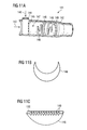
- a second embodiment of a mixing device 141 is depicted in Figures 11a to 11c.
- Drawing 11a in an exploded diagram.
- Said embodiment of the mixing device includes a tubular shell 142. At an upstream end of this shell, water 143 is laid on.
- a fuel diffusor tube 144 is arranged substantially perpendicularly to the flow of water143 inside the shell 142.
- the diffusor tube 144 is provided with a row of fuel outlet openings or nozzles 145 facing the downstream side of the tubular shell 142.
- Liquid fuel 146 is fed to said diffuser tube 144, whereupon the liquid fuel 146 is streaming out through said fuel outlet openings 145 as jet sprays and being mixed with water which is streaming around the diffusor tube 144 in a downstream direction of said tubular shell 142. Thereby an emulsion 147 of liquid fuel 146 and water 143 is formed as a spray of water and liquid fuel droplets.
- turbulators 148 are arranged inside the tubular shell 142 downstream the diffusor tube 144. In the depicted example according to figure 11a four turbulators 148 are inserted in the tube.
- the turbolators 148 may have the shape of a sickle, as in figure 11b , or of a circular segment, as in figure 11c . Further, as depicted in figure 11b , consecutive turbulators 148 are preferably rotated an angle (clockwise or anticlockwise) substantially amounting to 90 degrees to impart a swirl of the emulsion spray, whereby the spray outlet from the tubular shell 142 is formed as a swirl in the desired rotational direction.
- the turbulators 148 can be provided with teeth 149 at the downstream end of the surface 150 of the turbulator 148 facing radially inwards of the tubular shell 142. Due to these teeth 149 an increased turbulence will be imparted to the flow of the emulsion spray 147 sweeping downstream the mixing device 141.
- a number of said second embodiment of mixing devices 141 can be used to supply the main flame with the liquid fuel/water mix according to the aspect of the present invention. If there are two or more such mixing devices 141, they should be distributed in a symmetrical manner around the exit of the pilot 5a. The outlets of the tubular shell 142 should then be located just outside the pilot 5a exit, downstream said pilot 5a exit and upstream the exit of the first quarl section 4a.
- the second mixing device 141 can, in a further embodiment, be provided with an annular outlet of the same type as discussed for the fuel distributor 40.
- the fuel distributor 141 may have the same design as is described in the text above of Fig. 8 and forwards for the fuel distributor 40, which means that the design from above of the mixer 41 and downstream could be corresponding to a second embodiment of a fuel distributor.
- the outlet from mixing device 141 is provided with injection tubes which can emerge at the same location as where the mixer 41 is arranged in corresponding fuel distributor 40.
- any type of annular outlets may be arranged at the downstream ends of the second embodiment of mixing device 141 for supply of the emulsion spray to the main flame 7 in a flame surrounding manner.
- a relatively large amount of fuel can be added to the small pilot combustor 5 cooling air which corresponds to very rich equivalence ratios ( ⁇ > 3).
- Swirled cooling air and fuel and hot products of combustion from the small pilot combustor can very effectively sustain combustion of the main lean flame 7 below, at and above LBO limits.
- the combustion process is very stable and efficient because hot combustion products and very hot cooling air (above 750 °C), premixed with fuel, provide heat and active species (radicals) to the forward stagnation point P of the main flame recirculation zone 20.
- the small pilot combustor 5 combined with very hot cooling air (above 750 °C) premixed with fuel act as a flameless burner, where reactants (oxygen & fuel ) are premixed with products of combustion and a distributed flame is established at the forward stagnation point P of the swirl induced recirculation zone 20.
- the pilot combustor 5 can be fueled with gas or liquid fuel or both gas and liquid fuel.
- the imparted level of swirl and the swirl number (equation 1) is above the critical one (not lower then 0.6 and not higher then 0.8, see also fig. 3 ) at which vortex breakdown - recirculation zone 20 - will form and will be firmly positioned within the multi quarl 4a, 4b, 4c arrangement.
- the forward stagnation point P should be located within the quarl 4a, 4b, 4c and at the exit 6 of the pilot combustor 5.
- the process is initiated and stabilized by means of transporting heat and free radicals 31 from the previously combusted fuel and air, back upstream towards the flame front 7.
- the combustion process is very lean, as is the case in lean-partially premixed combustion systems, and as a result the combustion temperature is low, the equilibrium levels of free radicals is also very low.
- the free radicals produced by the combustion process quickly relax to the equilibrium level that corresponds to the temperature of the combustion products. This is due to the fact that the rate of this relaxation of the free radicals to equilibrium increases exponentially with increase in pressure, while on the other hand the equilibrium level of free radicals decreases exponentially with temperature decrease.
- the relaxation time of the free radicals can be short compared to the "transport" time required for the free radicals (symbolized by arrows 31) to be convected downstream, from the point where they were produced in the shear layer 18 of the main recirculation zone 20, back upstream, towards the flame front 7 and the forward stagnation point P of the main recirculation zone 20.
- High non-equilibrium levels of free radicals 32 are utilized to stabilize the main lean combustion 7.
- the scale of the small pilot combustor 5 is kept small and most of the combustion of fuel occurs in the lean premixed main combustor (at 7 and 18), and not in the small pilot combustor 5.
- the small pilot combustor 5, can be kept small, because the free radicals 32 are released near the forward stagnation point P of the main recirculation zone 20. This is generally the most efficient location to supply additional heat and free radicals to swirl stabilized combustion (7).
- the time scale between quench and utilization of free radicals 32 is very short not allowing free radicals 32 to relax to low equilibrium levels.
- the forward stagnation point P of the main-lean re-circulating zone 20 is maintained and aerodynamically stabilized in the quarl (4a), at the exit 6 of the small pilot combustor 5.
- zone 22 the exit of the small pilot combustor 5 is positioned on the centerline and at the small pilot combustor 5 throat 33.
Landscapes
- Engineering & Computer Science (AREA)
- Chemical & Material Sciences (AREA)
- Combustion & Propulsion (AREA)
- Mechanical Engineering (AREA)
- General Engineering & Computer Science (AREA)
Priority Applications (2)
| Application Number | Priority Date | Filing Date | Title |
|---|---|---|---|
| EP10178267A EP2434218A1 (de) | 2010-09-22 | 2010-09-22 | Brenner mit geringen NOx-Emissionen |
| PCT/EP2011/066285 WO2012038404A1 (en) | 2010-09-22 | 2011-09-20 | Burner with low nox emissions |
Applications Claiming Priority (1)
| Application Number | Priority Date | Filing Date | Title |
|---|---|---|---|
| EP10178267A EP2434218A1 (de) | 2010-09-22 | 2010-09-22 | Brenner mit geringen NOx-Emissionen |
Publications (1)
| Publication Number | Publication Date |
|---|---|
| EP2434218A1 true EP2434218A1 (de) | 2012-03-28 |
Family
ID=43799730
Family Applications (1)
| Application Number | Title | Priority Date | Filing Date |
|---|---|---|---|
| EP10178267A Ceased EP2434218A1 (de) | 2010-09-22 | 2010-09-22 | Brenner mit geringen NOx-Emissionen |
Country Status (2)
| Country | Link |
|---|---|
| EP (1) | EP2434218A1 (de) |
| WO (1) | WO2012038404A1 (de) |
Cited By (5)
| Publication number | Priority date | Publication date | Assignee | Title |
|---|---|---|---|---|
| WO2013179054A3 (en) * | 2012-05-31 | 2014-03-06 | SMITH, Andrew N P | An internal combustion engine and a method of operating an internal combustion engine |
| US9388983B2 (en) | 2013-10-03 | 2016-07-12 | Plum Combustion, Inc. | Low NOx burner with low pressure drop |
| EP2703721B1 (de) * | 2012-08-31 | 2019-05-22 | Ansaldo Energia IP UK Limited | Vormischbrenner |
| US11143407B2 (en) | 2013-06-11 | 2021-10-12 | Raytheon Technologies Corporation | Combustor with axial staging for a gas turbine engine |
| CN115704562A (zh) * | 2021-07-28 | 2023-02-17 | 中国航发商用航空发动机有限责任公司 | 火焰筒及单扇区燃烧室试验装置 |
Families Citing this family (5)
| Publication number | Priority date | Publication date | Assignee | Title |
|---|---|---|---|---|
| EP3056814A1 (de) * | 2015-02-13 | 2016-08-17 | General Electric Technology GmbH | Verfahren zur steuerung der kraftstoffverteilung zwischen verschiedenen stufen einer gasturbinenbrennkammer |
| US11156164B2 (en) | 2019-05-21 | 2021-10-26 | General Electric Company | System and method for high frequency accoustic dampers with caps |
| US11174792B2 (en) | 2019-05-21 | 2021-11-16 | General Electric Company | System and method for high frequency acoustic dampers with baffles |
| CN111649354B (zh) * | 2020-06-15 | 2022-03-29 | 江苏科技大学 | 一种三旋流分级旋流器及其燃烧室 |
| CN118463187B (zh) * | 2024-05-20 | 2024-10-25 | 四川大学 | 一种对冲无焰燃烧装置及对冲无焰燃烧方法 |
Citations (5)
| Publication number | Priority date | Publication date | Assignee | Title |
|---|---|---|---|---|
| GB1516177A (en) * | 1974-08-27 | 1978-06-28 | Mitsubishi Heavy Ind Ltd | Fuel combustion apparatus |
| US6311471B1 (en) * | 1999-01-08 | 2001-11-06 | General Electric Company | Steam cooled fuel injector for gas turbine |
| WO2005040682A2 (en) | 2003-09-05 | 2005-05-06 | Delavan Inc | Device for stabilizing combustion in gas turbine engines |
| WO2009078891A2 (en) * | 2007-09-14 | 2009-06-25 | Siemens Energy, Inc. | Secondary fuel delivery system |
| EP2107310A1 (de) * | 2008-04-01 | 2009-10-07 | Siemens Aktiengesellschaft | Brenner |
-
2010
- 2010-09-22 EP EP10178267A patent/EP2434218A1/de not_active Ceased
-
2011
- 2011-09-20 WO PCT/EP2011/066285 patent/WO2012038404A1/en not_active Ceased
Patent Citations (6)
| Publication number | Priority date | Publication date | Assignee | Title |
|---|---|---|---|---|
| GB1516177A (en) * | 1974-08-27 | 1978-06-28 | Mitsubishi Heavy Ind Ltd | Fuel combustion apparatus |
| US6311471B1 (en) * | 1999-01-08 | 2001-11-06 | General Electric Company | Steam cooled fuel injector for gas turbine |
| WO2005040682A2 (en) | 2003-09-05 | 2005-05-06 | Delavan Inc | Device for stabilizing combustion in gas turbine engines |
| WO2009078891A2 (en) * | 2007-09-14 | 2009-06-25 | Siemens Energy, Inc. | Secondary fuel delivery system |
| EP2107310A1 (de) * | 2008-04-01 | 2009-10-07 | Siemens Aktiengesellschaft | Brenner |
| WO2009121777A1 (en) | 2008-04-01 | 2009-10-08 | Siemens Aktiengesellschaft | Burner |
Cited By (9)
| Publication number | Priority date | Publication date | Assignee | Title |
|---|---|---|---|---|
| WO2013179054A3 (en) * | 2012-05-31 | 2014-03-06 | SMITH, Andrew N P | An internal combustion engine and a method of operating an internal combustion engine |
| GB2518097A (en) * | 2012-05-31 | 2015-03-11 | Khalil Abu Al-Rubb | An internal combustion engine and a method of operating an internal combustion engine |
| CN104508241A (zh) * | 2012-05-31 | 2015-04-08 | K·阿布阿尔-卢布 | 一种内燃发动机和一种内燃发动机的操作方法 |
| US9714607B2 (en) | 2012-05-31 | 2017-07-25 | Khalil Abu Al-Rubb | Internal combustion engine and a method of operating an internal combustion engine |
| GB2518097B (en) * | 2012-05-31 | 2018-07-18 | Khalil Abu Al Rubb | An internal combustion engine and a method of operating an internal combustion engine |
| EP2703721B1 (de) * | 2012-08-31 | 2019-05-22 | Ansaldo Energia IP UK Limited | Vormischbrenner |
| US11143407B2 (en) | 2013-06-11 | 2021-10-12 | Raytheon Technologies Corporation | Combustor with axial staging for a gas turbine engine |
| US9388983B2 (en) | 2013-10-03 | 2016-07-12 | Plum Combustion, Inc. | Low NOx burner with low pressure drop |
| CN115704562A (zh) * | 2021-07-28 | 2023-02-17 | 中国航发商用航空发动机有限责任公司 | 火焰筒及单扇区燃烧室试验装置 |
Also Published As
| Publication number | Publication date |
|---|---|
| WO2012038404A1 (en) | 2012-03-29 |
Similar Documents
| Publication | Publication Date | Title |
|---|---|---|
| EP2257743B1 (de) | Brenner | |
| US8033112B2 (en) | Swirler with gas injectors | |
| US8850820B2 (en) | Burner | |
| EP2434218A1 (de) | Brenner mit geringen NOx-Emissionen | |
| US8561409B2 (en) | Quarls in a burner | |
| US20110113787A1 (en) | Pilot combustor in a burner | |
| US20110033806A1 (en) | Fuel Staging in a Burner | |
| EP2263044B1 (de) | Grössenskalierung eines brenners |
Legal Events
| Date | Code | Title | Description |
|---|---|---|---|
| PUAI | Public reference made under article 153(3) epc to a published international application that has entered the european phase |
Free format text: ORIGINAL CODE: 0009012 |
|
| AK | Designated contracting states |
Kind code of ref document: A1 Designated state(s): AL AT BE BG CH CY CZ DE DK EE ES FI FR GB GR HR HU IE IS IT LI LT LU LV MC MK MT NL NO PL PT RO SE SI SK SM TR |
|
| AX | Request for extension of the european patent |
Extension state: BA ME RS |
|
| STAA | Information on the status of an ep patent application or granted ep patent |
Free format text: STATUS: THE APPLICATION HAS BEEN REFUSED |
|
| 18R | Application refused |
Effective date: 20120428 |