EP2434230A2 - Halte- und Befestigungsstruktur für flache Kollektoren oder photovoltaische Module in planparalleler Position, die ein Ableiten des Wassers ermöglicht - Google Patents
Halte- und Befestigungsstruktur für flache Kollektoren oder photovoltaische Module in planparalleler Position, die ein Ableiten des Wassers ermöglicht Download PDFInfo
- Publication number
- EP2434230A2 EP2434230A2 EP11006994A EP11006994A EP2434230A2 EP 2434230 A2 EP2434230 A2 EP 2434230A2 EP 11006994 A EP11006994 A EP 11006994A EP 11006994 A EP11006994 A EP 11006994A EP 2434230 A2 EP2434230 A2 EP 2434230A2
- Authority
- EP
- European Patent Office
- Prior art keywords
- photovoltaic modules
- supporting
- profiles
- flat panels
- longitudinal
- Prior art date
- Legal status (The legal status is an assumption and is not a legal conclusion. Google has not performed a legal analysis and makes no representation as to the accuracy of the status listed.)
- Withdrawn
Links
- XLYOFNOQVPJJNP-UHFFFAOYSA-N water Substances O XLYOFNOQVPJJNP-UHFFFAOYSA-N 0.000 title description 4
- 238000004873 anchoring Methods 0.000 claims description 6
- 238000000034 method Methods 0.000 claims description 3
- 238000009434 installation Methods 0.000 description 14
- 239000000463 material Substances 0.000 description 4
- 239000012528 membrane Substances 0.000 description 4
- 238000004078 waterproofing Methods 0.000 description 4
- 229920001971 elastomer Polymers 0.000 description 2
- 239000000806 elastomer Substances 0.000 description 2
- 238000012423 maintenance Methods 0.000 description 2
- 239000002184 metal Substances 0.000 description 2
- 229920000642 polymer Polymers 0.000 description 2
- 210000004027 cell Anatomy 0.000 description 1
- 230000008878 coupling Effects 0.000 description 1
- 238000010168 coupling process Methods 0.000 description 1
- 238000005859 coupling reaction Methods 0.000 description 1
- 230000005611 electricity Effects 0.000 description 1
- 238000004519 manufacturing process Methods 0.000 description 1
- 238000012986 modification Methods 0.000 description 1
- 230000004048 modification Effects 0.000 description 1
- 238000007789 sealing Methods 0.000 description 1
Images


Classifications
-
- H—ELECTRICITY
- H02—GENERATION; CONVERSION OR DISTRIBUTION OF ELECTRIC POWER
- H02S—GENERATION OF ELECTRIC POWER BY CONVERSION OF INFRARED RADIATION, VISIBLE LIGHT OR ULTRAVIOLET LIGHT, e.g. USING PHOTOVOLTAIC [PV] MODULES
- H02S20/00—Supporting structures for PV modules
- H02S20/20—Supporting structures directly fixed to an immovable object
- H02S20/22—Supporting structures directly fixed to an immovable object specially adapted for buildings
- H02S20/23—Supporting structures directly fixed to an immovable object specially adapted for buildings specially adapted for roof structures
-
- F—MECHANICAL ENGINEERING; LIGHTING; HEATING; WEAPONS; BLASTING
- F24—HEATING; RANGES; VENTILATING
- F24S—SOLAR HEAT COLLECTORS; SOLAR HEAT SYSTEMS
- F24S25/00—Arrangement of stationary mountings or supports for solar heat collector modules
- F24S25/30—Arrangement of stationary mountings or supports for solar heat collector modules using elongate rigid mounting elements extending substantially along the supporting surface, e.g. for covering buildings with solar heat collectors
- F24S25/33—Arrangement of stationary mountings or supports for solar heat collector modules using elongate rigid mounting elements extending substantially along the supporting surface, e.g. for covering buildings with solar heat collectors forming substantially planar assemblies, e.g. of coplanar or stacked profiles
- F24S25/35—Arrangement of stationary mountings or supports for solar heat collector modules using elongate rigid mounting elements extending substantially along the supporting surface, e.g. for covering buildings with solar heat collectors forming substantially planar assemblies, e.g. of coplanar or stacked profiles by means of profiles with a cross-section defining separate supporting portions for adjacent modules
-
- F—MECHANICAL ENGINEERING; LIGHTING; HEATING; WEAPONS; BLASTING
- F24—HEATING; RANGES; VENTILATING
- F24S—SOLAR HEAT COLLECTORS; SOLAR HEAT SYSTEMS
- F24S25/00—Arrangement of stationary mountings or supports for solar heat collector modules
- F24S25/30—Arrangement of stationary mountings or supports for solar heat collector modules using elongate rigid mounting elements extending substantially along the supporting surface, e.g. for covering buildings with solar heat collectors
- F24S25/33—Arrangement of stationary mountings or supports for solar heat collector modules using elongate rigid mounting elements extending substantially along the supporting surface, e.g. for covering buildings with solar heat collectors forming substantially planar assemblies, e.g. of coplanar or stacked profiles
- F24S25/37—Arrangement of stationary mountings or supports for solar heat collector modules using elongate rigid mounting elements extending substantially along the supporting surface, e.g. for covering buildings with solar heat collectors forming substantially planar assemblies, e.g. of coplanar or stacked profiles forming coplanar grids comprising longitudinal and transversal profiles
-
- F—MECHANICAL ENGINEERING; LIGHTING; HEATING; WEAPONS; BLASTING
- F24—HEATING; RANGES; VENTILATING
- F24S—SOLAR HEAT COLLECTORS; SOLAR HEAT SYSTEMS
- F24S25/00—Arrangement of stationary mountings or supports for solar heat collector modules
- F24S25/60—Fixation means, e.g. fasteners, specially adapted for supporting solar heat collector modules
- F24S25/63—Fixation means, e.g. fasteners, specially adapted for supporting solar heat collector modules for fixing modules or their peripheral frames to supporting elements
-
- F—MECHANICAL ENGINEERING; LIGHTING; HEATING; WEAPONS; BLASTING
- F24—HEATING; RANGES; VENTILATING
- F24S—SOLAR HEAT COLLECTORS; SOLAR HEAT SYSTEMS
- F24S40/00—Safety or protection arrangements of solar heat collectors; Preventing malfunction of solar heat collectors
- F24S40/40—Preventing corrosion; Protecting against dirt or contamination
- F24S40/44—Draining rainwater or condensation
-
- F—MECHANICAL ENGINEERING; LIGHTING; HEATING; WEAPONS; BLASTING
- F24—HEATING; RANGES; VENTILATING
- F24S—SOLAR HEAT COLLECTORS; SOLAR HEAT SYSTEMS
- F24S25/00—Arrangement of stationary mountings or supports for solar heat collector modules
- F24S2025/80—Special profiles
-
- Y—GENERAL TAGGING OF NEW TECHNOLOGICAL DEVELOPMENTS; GENERAL TAGGING OF CROSS-SECTIONAL TECHNOLOGIES SPANNING OVER SEVERAL SECTIONS OF THE IPC; TECHNICAL SUBJECTS COVERED BY FORMER USPC CROSS-REFERENCE ART COLLECTIONS [XRACs] AND DIGESTS
- Y02—TECHNOLOGIES OR APPLICATIONS FOR MITIGATION OR ADAPTATION AGAINST CLIMATE CHANGE
- Y02B—CLIMATE CHANGE MITIGATION TECHNOLOGIES RELATED TO BUILDINGS, e.g. HOUSING, HOUSE APPLIANCES OR RELATED END-USER APPLICATIONS
- Y02B10/00—Integration of renewable energy sources in buildings
- Y02B10/10—Photovoltaic [PV]
-
- Y—GENERAL TAGGING OF NEW TECHNOLOGICAL DEVELOPMENTS; GENERAL TAGGING OF CROSS-SECTIONAL TECHNOLOGIES SPANNING OVER SEVERAL SECTIONS OF THE IPC; TECHNICAL SUBJECTS COVERED BY FORMER USPC CROSS-REFERENCE ART COLLECTIONS [XRACs] AND DIGESTS
- Y02—TECHNOLOGIES OR APPLICATIONS FOR MITIGATION OR ADAPTATION AGAINST CLIMATE CHANGE
- Y02B—CLIMATE CHANGE MITIGATION TECHNOLOGIES RELATED TO BUILDINGS, e.g. HOUSING, HOUSE APPLIANCES OR RELATED END-USER APPLICATIONS
- Y02B10/00—Integration of renewable energy sources in buildings
- Y02B10/20—Solar thermal
-
- Y—GENERAL TAGGING OF NEW TECHNOLOGICAL DEVELOPMENTS; GENERAL TAGGING OF CROSS-SECTIONAL TECHNOLOGIES SPANNING OVER SEVERAL SECTIONS OF THE IPC; TECHNICAL SUBJECTS COVERED BY FORMER USPC CROSS-REFERENCE ART COLLECTIONS [XRACs] AND DIGESTS
- Y02—TECHNOLOGIES OR APPLICATIONS FOR MITIGATION OR ADAPTATION AGAINST CLIMATE CHANGE
- Y02E—REDUCTION OF GREENHOUSE GAS [GHG] EMISSIONS, RELATED TO ENERGY GENERATION, TRANSMISSION OR DISTRIBUTION
- Y02E10/00—Energy generation through renewable energy sources
- Y02E10/40—Solar thermal energy, e.g. solar towers
- Y02E10/47—Mountings or tracking
-
- Y—GENERAL TAGGING OF NEW TECHNOLOGICAL DEVELOPMENTS; GENERAL TAGGING OF CROSS-SECTIONAL TECHNOLOGIES SPANNING OVER SEVERAL SECTIONS OF THE IPC; TECHNICAL SUBJECTS COVERED BY FORMER USPC CROSS-REFERENCE ART COLLECTIONS [XRACs] AND DIGESTS
- Y02—TECHNOLOGIES OR APPLICATIONS FOR MITIGATION OR ADAPTATION AGAINST CLIMATE CHANGE
- Y02E—REDUCTION OF GREENHOUSE GAS [GHG] EMISSIONS, RELATED TO ENERGY GENERATION, TRANSMISSION OR DISTRIBUTION
- Y02E10/00—Energy generation through renewable energy sources
- Y02E10/50—Photovoltaic [PV] energy
Definitions
- This invention concerns structures used to support and mount flat panels such as solar panels or photovoltaic modules. These structures consist of at least two longitudinal profiles and two transversal "U-shaped" profiles, as well as other accessories to drain rainwater from a sloping surface.
- roofs with an angle of between 16° and 33° are ideal for the installation of such plants.
- Photovoltaic modules or solar panels should be fixed solidly to the roof or supporting surface using a variety of mounting systems, such as a structure anchored to the supporting section made generally of extruded profiles used to support the panels, and a range of accessories such as terminals, screws and bolts to fix the flat panels to the structure.
- mounting systems such as a structure anchored to the supporting section made generally of extruded profiles used to support the panels, and a range of accessories such as terminals, screws and bolts to fix the flat panels to the structure.
- European application EP 2012365 A1 published on 07/01/2009 , describes a device to be integrated on a roof for solar panels, and photovoltaic modules in particular, with a frame applied to each single module.
- All the modules are installed on the same plane, so the system drains the rainwater along the joints between adjacent modules, in both directions (parallel to the gutter line and perpendicular to the gutter line).
- the above frame consists of a flat element with the same surface area as the solar panel and a series of parts to be applied to the perimeter of the same element to seal the joints between adjacent flat panels or photovoltaic modules.
- European application EP 2034249 A1 published on 11/03/2009 , describes an integrated system for several solar panels on a roof, in particular panels for the production of hot water, with a frame for each module. All the modules are installed on the same plane, so the system drains the rainwater along the joints between adjacent modules, in both directions (parallel to the gutter line and perpendicular to the gutter line).
- the above frame has a top, a bottom and at least two channels with a "U-shaped" transversal section connecting the top and bottom.
- the structure consists of a primary frame, a series of "U-shaped" transversal profiles, and a series of devices for anchoring the primary frame to the supporting surface, the transversal profiles to the primary frame, and the flat panels or photovoltaic modules to the primary frame respectively.
- the profiles in the primary frame are arranged on the supporting surface with a longitudinal axis perpendicular to the gutter line and a distance between elements equal to the pitch of the flat panels along the direction parallel to the gutter line.
- the transversal "U-shaped" profiles rest on the primary frame, with the longitudinal axis parallel to the gutter line, and a distance between elements equal to the width of the flat panels perpendicular to the gutter line. Both frames have a transversal section so the profiles can act as a gutter.
- the aim of this invention is to solve the problems mentioned above, proposing a structure for supporting and fixing flat panels, photovoltaic modules in particular, that solves the above problems and makes it possible to adapt the structure of this invention to every type of photovoltaic module or flat panel, with or without a cornice, and without having to use custom solutions to adapt the system to the wide variety of photovoltaic modules or solar panels available.
- Another aim of this invention is to seal the joints between the panels, thanks to the configuration of the support structure and the method of assembly for mounting flat panels or photovoltaic modules.
- Another aim of this invention is to favour the drainage of rainwater using the surface of flat panels or photovoltaic modules and their longitudinal profiles.
- a further aim of this invention is to make maintenance or replacement of a single solar panel easy, without having to uninstall or move adjacent panels.
- the structure for supporting and mounting one or more flat panels or photovoltaic panels can be prepared for panels with or without a cornice.
- the longitudinal profiles, transversal profiles, accessories for anchoring the same profiles to the supporting surface, and the clamps for fixing the flat panels to the longitudinal profiles are made of metal or polymer-based material.
- the installation of the above structure for supporting and mounting one or more flat panels, in particular solar modules involves the following steps:
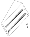
- FIG. 1A shows a 3D view of the first installation phase of the structure for supporting and mounting flat panels or photovoltaic modules; in particular Figure 1 A shows the following components: the supporting surface (1) and longitudinal profiles (2), positioned with the longitudinal axis parallel to the maximum slope of the roof or supporting surface (1).
- the supporting surface (1) is an inclined surface on which the profiles (2) are positioned with the longitudinal axis parallel to the maximum slope of the roof or supporting surface (1).
- the distance between these longitudinal profiles (2) is equal to the width of the flat panels or photovoltaic modules (4).
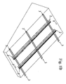
- Fig 1 B shows a 3D view of the second installation phase of the structure for supporting and mounting flat panels or photovoltaic modules; in particular Figure 1B shows the following components: supporting surface (1), the longitudinal profiles of the primary frame (2) and the "U-shaped" transversal profiles (3).
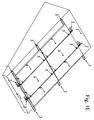
- FIG 1C shows a 3D view of the third installation phase of the structure for supporting and mounting flat panels or photovoltaic modules; in particular Figure 1C shows the following components: supporting surface (1), the longitudinal profiles of the primary frame (2), the transversal "U-shaped" profiles (3) and the mounting system (7).
- FIG 1D shows a 3D view of the fourth installation phase of the structure for supporting and mounting flat panels or photovoltaic modules; in particular Figure 1D shows the following parts: supporting surface (1), the longitudinal profiles of the primary frame (2), the "U-shaped" transversal profiles (3), the mounting system (7) and the flat panels or photovoltaic modules (4).
- FIG. 1E shows a 3D view of the fifth installation phase of the structure for supporting and mounting flat panels or photovoltaic modules; in particular Figure 1E shows the following parts: supporting surface (1), the longitudinal profiles of the primary frame (2), the "U-shaped" transversal profiles (3), the mounting system (5) and the flat panels or photovoltaic modules (4).
- FIG 1F shows a detailed 3D section of the structure for supporting and mounting flat panels or photovoltaic modules; in particular Figure 1F shows the following parts: the supporting surface (1), the longitudinal profiles of the primary frame (2), the "U-shaped" transversal profiles (3), the mounting system (5) and flat panels or photovoltaic modules (4).
- Fig 2A shows an exploded cross section of the structure for supporting and mounting flat panels or photovoltaic modules, with: the supporting surface (1), the longitudinal profiles of the primary frame (2), the "U-shaped" transversal profiles (3). These profiles consist of a "U-shaped" section (3A) used to collect rainwater and two side flanges under the "U-shaped” section, one on the right (3B) and one on the left (3C) of the above profile, which drain rainwater to the drain of the primary frame longitudinal profile (2).
- the flat panels or photovoltaic modules are mounted on the primary frame profiles by suitable fasteners (5), (6) and (7), while the primary frame profiles are fixed to the supporting surface with appropriate fasteners (8A), (8B), (8A') and (8B').
- Figure 2A also shows elastomers (9) and (10) covering the seat of the edge on the flat panels or photovoltaic modules (4).
- Fig 2B shows an assembled cross section of the structure for supporting and mounting flat panels or photovoltaic modules, with: the supporting surface (1), the longitudinal profiles of the primary frame (2), the "U-shaped" transversal profiles (3). These profiles consist of a "U-shaped” section (3A) used to collect rainwater and two side flanges under the "U-shaped” section, one on the right (3B) and one on the left (3C) of the above profile, which drain rainwater to the drain of the primary frame longitudinal profile (2).
- the flat panels or photovoltaic modules are mounted on the primary frame profiles by suitable fasteners (5), (6) and (7), while the primary frame profiles are fixed to the supporting surface with appropriate fasteners (8).
- the structure for supporting and mounting one or more flat panels or photovoltaic panels (4) can be prepared for panels with or without a cornice.
- the longitudinal profiles for the primary frame (2) and "U-shaped" transversal sections (3), the accessories for anchoring (8) the above profiles (2) to the supporting surface (1) and the above flat panels or photovoltaic modules (4) are made of metal or polymer-based material.
- Fig 3A shows the detailed cross section of the structure for supporting and mounting flat panels or photovoltaic modules assembled.
- Fig. 3A shows the following parts: the supporting surface (1), the longitudinal profiles of the primary frame (2), the "U-shaped" transversal profiles (3). These profiles consist of a "U-shaped” section (3A) used to collect rainwater and two side flanges under the "U-shaped” section, one on the right (3B) and one on the left (3C) of the above profile, which drain rainwater to the drain of the primary frame longitudinal profile (2).
- the flat panels or photovoltaic modules (4) are mounted on the primary frame profiles with suitable fasteners (5) and (6), and the primary frame profiles are fixed to the supporting surface with appropriate fasteners (8).
- Fig. 3B shows an detailed view of the cross section of the structure for supporting and mounting flat panels or photovoltaic modules assembled, with: the supporting surface (1), the longitudinal profiles of the primary frame (2), the "U-shaped" transversal profiles (3). These profiles consist of a "U-shaped” section (3A) used to collect rainwater and two side flanges under the "U-shaped” section, one on the right (3B) and one on the left (3C) of the above profile, which drain rainwater to the drain of the primary frame longitudinal profile (2).
- the flat panels or photovoltaic modules (4) are mounted on the primary frame profiles by suitable fasteners (5), (6) and (7), while the primary frame profiles are fixed to the supporting surface with appropriate fasteners (8A), (8B), (8A') and (8B').
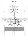
- Fig. 3C shows the detailed exploded cross section of the structure for supporting and mounting flat panels or photovoltaic modules.
- Fig. 3C shows how the edge of the flat panel or photovoltaic module (4) can be partially or completely covered by special elastomers (9) and (10), comprising at least one vertical side (9B) and (10B) and two horizontal sides (9A) and (9C), (10A) and (10C).
- the elastomeric elements (9) and (10) are arranged on part of the inactive portion (i.e. the portion of the solar cell surface which is not used) on the upper surface of the flat panel or photovoltaic module (4).
- Elastomeric elements (9A) and (10A), (9B) and (10B) are advantageously positioned on the entire inactive portion of the upper surface of flat panel (4), along the top and bottom edge.
- the elastomeric elements substantially a "C-shaped" section, corresponding to the profile of the panel or photovoltaic module (4), make coupling between the elastomeric element (9) and (10) and the top edge of the flat panel or photovoltaic module (4), easy.
- the size of the "C" sections was chosen so they come into contact with the upper edge of the flat panel or photovoltaic module (4), making it easier to hold in place, representing an even more advantageous feature. This makes it easy to create a watertight overlap between two flat panels or photovoltaic modules (4).
- the thickness of the elastomeric elements (9) and (10) is advantageous, as it is less than half the thickness of the flat panel or photovoltaic module (4), so the installation maintains a sufficient slope to drain rainwater.
- Vertical elastomeric elements (9B) and (10B) are arranged at least partially on the lateral surface of the flat panel or photovoltaic module (4), to tighten the fastening system (7).
- the first and second elastomeric element (9) and (10) can be integrated with one another, which represents another advantage.
- Lower side flanges (3B) and (3C) of the transversal "U-shaped" profiles are fixed at the height of elements (2C') and (2C) respectively, of the primary frame longitudinal profile (2).
- Flanges (3B) and (3C) drain the rainwater respectively in areas (2D') and (2D) of the primary frame longitudinal profile (2).
- the distance between the holes (2B), in flange (2A) and hole (2B'), in flange (2A') along the longitudinal axis, must be calculated according to the characteristics of the supporting surface (1).
- Said hole (2B) is to insert fasteners (8A) and (8B), while hole (2B') is to insert fasteners (8A') and (8B').
- the overlapping part of the primary frame longitudinal profile (2) is characterized by a groove (2E) in which the appropriate fasteners (5), (6) and (7) are inserted to fix the flat panels or photovoltaic modules (4).
- This groove (2E) runs along the length of the profile and the longitudinal axes, parallel to the longitudinal axis of the profile.
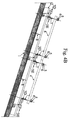
- Fig 4A shows the longitudinal section of the structure for supporting and mounting flat panels or photovoltaic modules assembled, with the fasteners (8), the longitudinal profile of the primary frame (2), the supporting surface (1), and the "U-shaped" transversal profiles (3).
- the side flanges (3D) and (3E), respectively for fixing elements (2C') and (2C) of primary frame longitudinal profile (2), and lower side flange (3B), which drains the rainwater to the drain in the primary frame longitudinal profile (2) are shown for this "U-shaped" profile.
- Fig 4B shows the exploded longitudinal section of the structure for supporting and mounting flat panels or photovoltaic modules, with fasteners (8A) and (8B) for fixing the longitudinal profile of the primary frame (2) to the supporting surface (1), the transversal "U-shaped" profile (3) and fasteners (5), (6) and (7) for fixing the flat panels or photovoltaic modules (4).
- the side flanges (3D) and (3E), respectively for fixing the vertical elements of the primary frame longitudinal profile (2), and lower side flange (3B), which drains the rainwater to the drain in the primary frame longitudinal profile (2) are shown for this "U-shaped" profile.
- Fig 4C shows a detailed view of the exploded longitudinal section of the structure for supporting and mounting flat panels or photovoltaic modules, with fasteners (8A) (8B) for fixing the longitudinal profile of the primary frame (2) to the supporting surface (1), the transversal "U-shaped” profile (3) and fasteners (5), (6) and (7) for fixing the flat panels or photovoltaic modules (4).
- the side flanges (3D) and (3E), respectively for fixing the vertical elements of the primary frame longitudinal profile (2), and lower side flange (3B), which drains the rainwater to the drain in the primary frame longitudinal profile (2) are shown for this "U-shaped" profile.
- Fig 5 shows a view from above of the structure for supporting and mounting flat panels or photovoltaic modules, highlighting the location of the supporting surface (1), the longitudinal profiles of the primary frame (2), the "U-shaped" transversal profiles (3) and the flat panels or photovoltaic modules (4).
Landscapes
- Engineering & Computer Science (AREA)
- Thermal Sciences (AREA)
- Mechanical Engineering (AREA)
- General Engineering & Computer Science (AREA)
- Physics & Mathematics (AREA)
- Life Sciences & Earth Sciences (AREA)
- Sustainable Development (AREA)
- Combustion & Propulsion (AREA)
- Chemical & Material Sciences (AREA)
- Sustainable Energy (AREA)
- Civil Engineering (AREA)
- Architecture (AREA)
- Structural Engineering (AREA)
- Roof Covering Using Slabs Or Stiff Sheets (AREA)
- Photovoltaic Devices (AREA)
- Processing Of Solid Wastes (AREA)
Applications Claiming Priority (1)
| Application Number | Priority Date | Filing Date | Title |
|---|---|---|---|
| IT000155A ITAN20100155A1 (it) | 2010-09-24 | 2010-09-24 | Struttura per il supporto e il fissaggio di pannelli piani o moduli fotovoltaici in posizione complanare, e per lo smaltimento delle acque meteoriche |
Publications (2)
| Publication Number | Publication Date |
|---|---|
| EP2434230A2 true EP2434230A2 (de) | 2012-03-28 |
| EP2434230A3 EP2434230A3 (de) | 2013-08-14 |
Family
ID=43738698
Family Applications (1)
| Application Number | Title | Priority Date | Filing Date |
|---|---|---|---|
| EP11006994.5A Withdrawn EP2434230A3 (de) | 2010-09-24 | 2011-08-26 | Halte- und Befestigungsstruktur für flache Kollektoren oder photovoltaische Module in planparalleler Position, die ein Ableiten des Wassers ermöglicht |
Country Status (2)
| Country | Link |
|---|---|
| EP (1) | EP2434230A3 (de) |
| IT (1) | ITAN20100155A1 (de) |
Cited By (8)
| Publication number | Priority date | Publication date | Assignee | Title |
|---|---|---|---|---|
| NL2009921C2 (nl) * | 2012-12-03 | 2014-06-04 | Scx Solar B V | Montagesysteem voor het op een bouwwerk bevestigen van een fotovoltaisch systeem, bouwwerk omvattende dit montagesysteem en werkwijze voor het bevestigen van een montagesysteem op een bouwwerk. |
| WO2014118726A1 (en) | 2013-02-04 | 2014-08-07 | Instytut Inżynierii Materiałów Polimerowych I Barwników | Polymer plate of a solar absorber |
| NL2012512A (nl) * | 2014-03-26 | 2016-01-07 | Scx Solar B V | Inrichting en werkwijze voor het plaatsen van een zonnepaneel op een bouwwerk. |
| CN109025095A (zh) * | 2018-08-28 | 2018-12-18 | 广东旭科太阳能科技有限公司 | 一种具有防水结构的光伏棚架 |
| CN114362644A (zh) * | 2022-01-13 | 2022-04-15 | 北京江河智慧光伏建筑有限公司 | 用于无边框光伏组件的导水支撑系统 |
| SE2151412A1 (en) * | 2020-11-20 | 2022-05-21 | Isola As | System for attaching solar cells to ceilings or wall facades |
| CN115822188A (zh) * | 2022-11-23 | 2023-03-21 | 浙江金贝能源科技有限公司 | 一种无框光伏组件建筑一体化安装结构 |
| EP4227598A1 (de) * | 2022-02-15 | 2023-08-16 | Julius Fritsche GmbH | Solaranlage mit positionierleiste |
Families Citing this family (1)
| Publication number | Priority date | Publication date | Assignee | Title |
|---|---|---|---|---|
| US10547270B2 (en) | 2016-02-12 | 2020-01-28 | Solarcity Corporation | Building integrated photovoltaic roofing assemblies and associated systems and methods |
Citations (5)
| Publication number | Priority date | Publication date | Assignee | Title |
|---|---|---|---|---|
| WO2003007688A2 (en) | 2001-07-20 | 2003-01-30 | Unirac, Inc. | A system for removably and adjustably mounting a device on a surface |
| WO2004055294A1 (en) | 2002-12-16 | 2004-07-01 | Vkr Holding A/S | Side flashing member method of making such a side flashing member and a flashing assembly |
| WO2008145913A2 (fr) | 2007-04-20 | 2008-12-04 | Arcelormittal - Stainless And Nickel Alloys | Structure pour le montage dans une paroi d'un bâtiment de bâtis destinés à supporter des panneaux tels que des panneaux photovoltaïques |
| EP2012365A1 (de) | 2007-07-06 | 2009-01-07 | Terreal | Vorrichtung zur Integration von Solarmoduln auf ein Dach, insbesondere für photovoltaische Moduln |
| EP2034249A1 (de) | 2007-09-10 | 2009-03-11 | Terreal | Vorrichtung zum Einbau eines Solarzellenpaneels auf einem Dach |
Family Cites Families (7)
| Publication number | Priority date | Publication date | Assignee | Title |
|---|---|---|---|---|
| JP3461747B2 (ja) * | 1999-02-17 | 2003-10-27 | 元旦ビューティ工業株式会社 | 太陽電池パネルを用いた外装構造 |
| DE202007010520U1 (de) * | 2007-07-28 | 2007-10-04 | Aleris Aluminum Vogt Gmbh | Vorrichtung zur Abstützung eines Plattenelementes |
| DE102008051902A1 (de) * | 2008-10-16 | 2010-04-22 | Öller, Franz, Dipl.-Ing. (FH) | Dichtes Dach aus gerahmten Standard-Photovoltaikmodulen durch Verwendung eines Rinnensystems |
| EP2187146B1 (de) * | 2008-11-14 | 2019-01-02 | Böcherer, Hans | Traganordnung |
| FR2938566B1 (fr) * | 2008-11-17 | 2012-01-13 | Alain Poivet | Dispositif de support de panneaux de cellules photovoltaiques et systeme de support de panneaux photovoltaiques |
| DE202009005576U1 (de) * | 2009-04-14 | 2009-06-25 | Widmayr, Josef | Tragrahmen, Rahmengestell und damit gebauter Carport |
| DE202010002489U1 (de) * | 2010-01-14 | 2010-06-10 | Altec Solartechnik Ag | Indach-Solarkollektormontageanordnung |
-
2010
- 2010-09-24 IT IT000155A patent/ITAN20100155A1/it unknown
-
2011
- 2011-08-26 EP EP11006994.5A patent/EP2434230A3/de not_active Withdrawn
Patent Citations (5)
| Publication number | Priority date | Publication date | Assignee | Title |
|---|---|---|---|---|
| WO2003007688A2 (en) | 2001-07-20 | 2003-01-30 | Unirac, Inc. | A system for removably and adjustably mounting a device on a surface |
| WO2004055294A1 (en) | 2002-12-16 | 2004-07-01 | Vkr Holding A/S | Side flashing member method of making such a side flashing member and a flashing assembly |
| WO2008145913A2 (fr) | 2007-04-20 | 2008-12-04 | Arcelormittal - Stainless And Nickel Alloys | Structure pour le montage dans une paroi d'un bâtiment de bâtis destinés à supporter des panneaux tels que des panneaux photovoltaïques |
| EP2012365A1 (de) | 2007-07-06 | 2009-01-07 | Terreal | Vorrichtung zur Integration von Solarmoduln auf ein Dach, insbesondere für photovoltaische Moduln |
| EP2034249A1 (de) | 2007-09-10 | 2009-03-11 | Terreal | Vorrichtung zum Einbau eines Solarzellenpaneels auf einem Dach |
Cited By (12)
| Publication number | Priority date | Publication date | Assignee | Title |
|---|---|---|---|---|
| NL2009921C2 (nl) * | 2012-12-03 | 2014-06-04 | Scx Solar B V | Montagesysteem voor het op een bouwwerk bevestigen van een fotovoltaisch systeem, bouwwerk omvattende dit montagesysteem en werkwijze voor het bevestigen van een montagesysteem op een bouwwerk. |
| EP2738822A1 (de) | 2012-12-03 | 2014-06-04 | SCX Solar B.V. | Montagesystem zur Installation von Paneelen, beispielsweise von photovoltaischen Paneelen, an einem Gebäude |
| WO2014118726A1 (en) | 2013-02-04 | 2014-08-07 | Instytut Inżynierii Materiałów Polimerowych I Barwników | Polymer plate of a solar absorber |
| NL2012512A (nl) * | 2014-03-26 | 2016-01-07 | Scx Solar B V | Inrichting en werkwijze voor het plaatsen van een zonnepaneel op een bouwwerk. |
| CN109025095A (zh) * | 2018-08-28 | 2018-12-18 | 广东旭科太阳能科技有限公司 | 一种具有防水结构的光伏棚架 |
| CN109025095B (zh) * | 2018-08-28 | 2024-04-16 | 广东旭科太阳能科技有限公司 | 一种具有防水结构的光伏棚架 |
| SE2151412A1 (en) * | 2020-11-20 | 2022-05-21 | Isola As | System for attaching solar cells to ceilings or wall facades |
| SE546899C2 (en) * | 2020-11-20 | 2025-03-04 | Isola Solar As | System for fastening solar cells to roofs or wall facades of buildnings and a method |
| CN114362644A (zh) * | 2022-01-13 | 2022-04-15 | 北京江河智慧光伏建筑有限公司 | 用于无边框光伏组件的导水支撑系统 |
| CN114362644B (zh) * | 2022-01-13 | 2024-03-22 | 北京江河智慧光伏建筑有限公司 | 用于无边框光伏组件的导水支撑系统 |
| EP4227598A1 (de) * | 2022-02-15 | 2023-08-16 | Julius Fritsche GmbH | Solaranlage mit positionierleiste |
| CN115822188A (zh) * | 2022-11-23 | 2023-03-21 | 浙江金贝能源科技有限公司 | 一种无框光伏组件建筑一体化安装结构 |
Also Published As
| Publication number | Publication date |
|---|---|
| EP2434230A3 (de) | 2013-08-14 |
| ITAN20100155A1 (it) | 2012-03-25 |
Similar Documents
| Publication | Publication Date | Title |
|---|---|---|
| EP2434230A2 (de) | Halte- und Befestigungsstruktur für flache Kollektoren oder photovoltaische Module in planparalleler Position, die ein Ableiten des Wassers ermöglicht | |
| US8341900B2 (en) | Structure for mounting on a building wall frames for holding panels such as photovoltaic panels | |
| DK2784241T3 (en) | Roofing for solar energy utilization | |
| US6212837B1 (en) | Rain water diverter system for deck structures | |
| US8701373B2 (en) | Flashing member with a compensation member, a kit including such a flashing member and a method for mounting a flashing for a roof window | |
| EP2196594A1 (de) | Bauelement zur Verkleidung von Gebäuden | |
| WO2017162433A1 (en) | Solar panel mounting | |
| EP3231956A1 (de) | Teleskoprinne, speziell für dachfenster | |
| KR20130001553U (ko) | 태양광 모듈 패널이 설치된 지붕구조 | |
| EP3319228B1 (de) | Integriertes solarpaneel auf einem ziegeldach | |
| EP2592364B1 (de) | Integriertes Struktursystem zur Montage von photovoltaischen Kollektoren | |
| US9294032B2 (en) | Modular roof solar panel for conventional roof and roofing integration | |
| EP2546585A1 (de) | Integriertes Panelsystem | |
| EP2886973A1 (de) | Photovoltaiksystem und Verfahren zu dessen Installation | |
| US12132441B2 (en) | System and method for connecting and fixing framed solar panels to make a wheatherproof building-integrated modular surface | |
| EP3571449B1 (de) | Abdeckungsvorrichtung | |
| US9771717B1 (en) | Metal ceiling panel system with retaining clips and method | |
| EP2767778A1 (de) | System zur Montage von Photovoltaikmodulen zur Installation auf dem Boden oder auf Gebäuden | |
| EP2757592A1 (de) | Montagesystem für photovoltaische Module und plattenförmige Komponenten | |
| KR101330076B1 (ko) | 무볼트 방식 지붕용 채광구조 및 이의 시공방법 | |
| US20260117519A1 (en) | Structure systems, structures with integrated solar racking systems, post and frame components, and related methods | |
| ITAN20100121A1 (it) | Sistema per il supporto e il fissaggio di uno o più pannelli piani o moduli fotovoltaici su superfici orizzontali, verticali o inclinate, che consente lo smaltimento delle acque meteoriche | |
| JP4509949B2 (ja) | 外装構造 | |
| EP2647923A1 (de) | Modul zur Herstellung einer Dachabdeckung mit Stützen zur Auflage von Photovoltaikpanele | |
| AU2013100325A4 (en) | Light Weight Solar Metal Roofing |
Legal Events
| Date | Code | Title | Description |
|---|---|---|---|
| PUAI | Public reference made under article 153(3) epc to a published international application that has entered the european phase |
Free format text: ORIGINAL CODE: 0009012 |
|
| AK | Designated contracting states |
Kind code of ref document: A2 Designated state(s): AL AT BE BG CH CY CZ DE DK EE ES FI FR GB GR HR HU IE IS IT LI LT LU LV MC MK MT NL NO PL PT RO RS SE SI SK SM TR |
|
| AX | Request for extension of the european patent |
Extension state: BA ME |
|
| PUAL | Search report despatched |
Free format text: ORIGINAL CODE: 0009013 |
|
| AK | Designated contracting states |
Kind code of ref document: A3 Designated state(s): AL AT BE BG CH CY CZ DE DK EE ES FI FR GB GR HR HU IE IS IT LI LT LU LV MC MK MT NL NO PL PT RO RS SE SI SK SM TR |
|
| AX | Request for extension of the european patent |
Extension state: BA ME |
|
| RIC1 | Information provided on ipc code assigned before grant |
Ipc: F24J 2/46 20060101ALI20130711BHEP Ipc: H01L 31/042 20060101ALI20130711BHEP Ipc: F24J 2/52 20060101AFI20130711BHEP |
|
| PUAJ | Public notification under rule 129 epc |
Free format text: ORIGINAL CODE: 0009425 |
|
| 32PN | Public notification |
Free format text: NOTING OF LOSS OF RIGHTS PURSUANT TO RULE 112(1) EPC (EPO FORM 1097 DATED 08-07-2014) |
|
| STAA | Information on the status of an ep patent application or granted ep patent |
Free format text: STATUS: THE APPLICATION IS DEEMED TO BE WITHDRAWN |
|
| 18D | Application deemed to be withdrawn |
Effective date: 20140215 |