EP2434280A2 - Zerstörungsfreie Prüfung einer Struktur in einem Flugzeug - Google Patents
Zerstörungsfreie Prüfung einer Struktur in einem Flugzeug Download PDFInfo
- Publication number
- EP2434280A2 EP2434280A2 EP11182121A EP11182121A EP2434280A2 EP 2434280 A2 EP2434280 A2 EP 2434280A2 EP 11182121 A EP11182121 A EP 11182121A EP 11182121 A EP11182121 A EP 11182121A EP 2434280 A2 EP2434280 A2 EP 2434280A2
- Authority
- EP
- European Patent Office
- Prior art keywords
- coils
- coil
- edge
- network
- electrical signal
- Prior art date
- Legal status (The legal status is an assumption and is not a legal conclusion. Google has not performed a legal analysis and makes no representation as to the accuracy of the status listed.)
- Granted
Links
- 238000009659 non-destructive testing Methods 0.000 title claims description 7
- 230000007547 defect Effects 0.000 claims abstract description 41
- 238000000034 method Methods 0.000 claims abstract description 28
- 230000000694 effects Effects 0.000 claims abstract description 26
- 230000003213 activating effect Effects 0.000 claims abstract description 4
- 238000007689 inspection Methods 0.000 claims abstract description 3
- 238000001514 detection method Methods 0.000 claims description 27
- 238000012545 processing Methods 0.000 claims description 22
- 239000000463 material Substances 0.000 claims description 17
- 239000002184 metal Substances 0.000 claims description 11
- 230000004913 activation Effects 0.000 claims description 7
- 238000004458 analytical method Methods 0.000 claims description 6
- 230000010363 phase shift Effects 0.000 claims description 5
- 238000011156 evaluation Methods 0.000 claims description 3
- 238000005259 measurement Methods 0.000 claims description 3
- 238000000926 separation method Methods 0.000 claims description 2
- 230000001066 destructive effect Effects 0.000 abstract description 3
- 238000003745 diagnosis Methods 0.000 description 8
- 238000009434 installation Methods 0.000 description 7
- 230000006870 function Effects 0.000 description 5
- 230000008859 change Effects 0.000 description 4
- 230000032683 aging Effects 0.000 description 3
- 238000012544 monitoring process Methods 0.000 description 3
- 238000000465 moulding Methods 0.000 description 3
- 241000861223 Issus Species 0.000 description 2
- 238000000429 assembly Methods 0.000 description 2
- 238000004590 computer program Methods 0.000 description 2
- 230000002950 deficient Effects 0.000 description 2
- 238000010586 diagram Methods 0.000 description 2
- 230000005672 electromagnetic field Effects 0.000 description 2
- 230000036541 health Effects 0.000 description 2
- 238000013507 mapping Methods 0.000 description 2
- 239000013521 mastic Substances 0.000 description 2
- 239000000523 sample Substances 0.000 description 2
- 230000002159 abnormal effect Effects 0.000 description 1
- 230000006978 adaptation Effects 0.000 description 1
- 230000003321 amplification Effects 0.000 description 1
- 230000000712 assembly Effects 0.000 description 1
- 238000004364 calculation method Methods 0.000 description 1
- 239000003086 colorant Substances 0.000 description 1
- 230000005284 excitation Effects 0.000 description 1
- 239000000945 filler Substances 0.000 description 1
- 238000001914 filtration Methods 0.000 description 1
- 230000000977 initiatory effect Effects 0.000 description 1
- 239000003350 kerosene Substances 0.000 description 1
- 239000007788 liquid Substances 0.000 description 1
- 238000003199 nucleic acid amplification method Methods 0.000 description 1
- 238000013021 overheating Methods 0.000 description 1
- 244000045947 parasite Species 0.000 description 1
- 230000035699 permeability Effects 0.000 description 1
- 238000006116 polymerization reaction Methods 0.000 description 1
- 230000010349 pulsation Effects 0.000 description 1
- 230000008439 repair process Effects 0.000 description 1
- 230000004044 response Effects 0.000 description 1
- 238000012360 testing method Methods 0.000 description 1
- 238000012800 visualization Methods 0.000 description 1
Images



Classifications
-
- G—PHYSICS
- G01—MEASURING; TESTING
- G01N—INVESTIGATING OR ANALYSING MATERIALS BY DETERMINING THEIR CHEMICAL OR PHYSICAL PROPERTIES
- G01N27/00—Investigating or analysing materials by the use of electric, electrochemical, or magnetic means
- G01N27/72—Investigating or analysing materials by the use of electric, electrochemical, or magnetic means by investigating magnetic variables
- G01N27/82—Investigating or analysing materials by the use of electric, electrochemical, or magnetic means by investigating magnetic variables for investigating the presence of flaws
- G01N27/90—Investigating or analysing materials by the use of electric, electrochemical, or magnetic means by investigating magnetic variables for investigating the presence of flaws using eddy currents
- G01N27/9046—Investigating or analysing materials by the use of electric, electrochemical, or magnetic means by investigating magnetic variables for investigating the presence of flaws using eddy currents by analysing electrical signals
-
- G—PHYSICS
- G01—MEASURING; TESTING
- G01N—INVESTIGATING OR ANALYSING MATERIALS BY DETERMINING THEIR CHEMICAL OR PHYSICAL PROPERTIES
- G01N27/00—Investigating or analysing materials by the use of electric, electrochemical, or magnetic means
- G01N27/72—Investigating or analysing materials by the use of electric, electrochemical, or magnetic means by investigating magnetic variables
- G01N27/82—Investigating or analysing materials by the use of electric, electrochemical, or magnetic means by investigating magnetic variables for investigating the presence of flaws
- G01N27/90—Investigating or analysing materials by the use of electric, electrochemical, or magnetic means by investigating magnetic variables for investigating the presence of flaws using eddy currents
- G01N27/904—Investigating or analysing materials by the use of electric, electrochemical, or magnetic means by investigating magnetic variables for investigating the presence of flaws using eddy currents with two or more sensors
Definitions
- the present invention relates to the field of non-destructive testing techniques for detecting defects in metal structures, and more particularly, for the detection of cracks in inaccessible or inaccessible areas of the structure of an aircraft.
- Aircraft structures or mechanical parts are regularly checked to detect the presence of cracks in order to proceed, if necessary, to appropriate repairs.
- a non-destructive control system comprising a probe consisting of a plurality of coils fixed on the surface to be controlled. Subassemblies of these coils are sequentially powered and connected in series to simulate continuous scanning of the surface to be inspected by a probe. The initialization of the coils is carried out in the air before their installation on the surface and the signals coming from the subsets of coils are compared with each other to detect surface cracks in the structure.
- this system can also trigger alerts that do not necessarily correspond to cracks.
- electromagnetic parasites and / or temperature changes and / or changes in the mechanical properties of the structure can interfere with the flow of eddy currents, and result in impedance variation at the coil levels.
- the object of the present invention is to provide a method of non-destructive eddy current testing to detect possible defects in a metal structure overcoming the aforementioned drawbacks, in particular by making it possible to detect cracks without being disturbed by external factors. or a natural evolution of the structure.
- the invention relates to an eddy-current non-destructive testing method for detecting defects in a metal structure by means of a coil array attached to a surface of said structure, including activation of the coils, and measurement of electrical signals representative of the eddy currents, said method further comprising a time evaluation of a variation of the electrical signal of each of the coils taking as a reference an edge effect corresponding to a specific electrical signal from at least one coil installed at the edge of the surface, the level of said variation being indicative of the presence of defects in the structure.
- the method according to the invention makes it possible to have an automatic, precise, and robust detection faults in areas where there is no direct access while avoiding false alarms.
- the method comprises a step for comparing the specific electric signals of the coils installed at the edge of the surface.
- the method comprises an analysis of the electrical signals from the coils with respect to detection thresholds determined as a function of the positions of said coils on the surface.
- the method comprises a calibration of said network of coils at intervals determined in time to analyze the evolution on the surface of said structure.
- the method comprises a separation of the electrical signal from any coil having an anomaly.
- the invention also relates to an eddy current non-destructive testing device for detecting defects in a metal structure by means of a coil network fixed on a surface of said structure, comprising activation means for activating the coils, measuring means for measuring electrical signals representative of the eddy currents, and data processing means for evaluating over time a variation of the electrical signal of each of the coils by taking as a reference an edge effect corresponding to a specific electrical signal from at least one coil installed at the edge of the surface, the level of said variation being indicative of the presence of defects in the structure.
- the invention also relates to an aircraft comprising a metal structure and a structure control device implementing the method according to any one of the above characteristics.
- the invention relates to the detection of defects in a metal structure by eddy currents using an onboard coil array.
- the principle underlying the invention is to analyze the signals from the coils with respect to an edge effect.
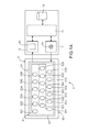
- Figs. 1A and 1B schematically illustrate a device that can be used to perform the eddy current non-destructive testing method for detecting defects in a metal structure of an aircraft, according to the invention.
- the device 1 comprises, a network 5 of coils, activation means 7 for activating the coils, measurement means 9 for measuring electric signals representative of the eddy currents, calculation or data processing means 11 for processing and analyzing the electrical signals, and memory means 13 for storing data or code instructions of a computer program.
- the coil array 5 is comprised of a plurality of coils 511-536 connected in parallel, to be individually processable as a plurality of eddy current sensors.
- the coils 511-536 can be of planar or volume form depending on the thickness, the bulk or other factors of the structure 3 to be controlled.
- each coil may have a diameter of about 0.5 mm to 1 mm, and a height of about 1 mm to 5 mm.
- the diameter of the coils 511-536 can be adapted to the smallest defect to be detected, usually of the order of 1 mm, and can even detect cracks below 1 mm.
- the device 1 can detect defects at several levels of depth in the structure 3. This is particularly advantageous in assemblies which do not have no direct access to the skin of the structure.
- the network 5 of coils is arranged to cover the entire surface 31 of the structure 3 to inspect.
- the network 5 of coils has a frame 15 or electromagnetic shield to isolate it from its environment while allowing for each coil, an individual detection large enough to avoid the existence of dead zones between the coils 511-536.
- the coil array 5 can continuously diagnose the entire area bounded by the frame 15.
- the network 5 of coils is held on the surface 31 to be inspected by a flexible material 17 having an adhering power, filler type so non-aggressive for the structure to be controlled, and resistant to aggressive liquids such as kerosene .
- the flexible material 17 is used to assemble each of the coils on the surface 31 of the structure.
- This flexible material 17 makes it possible to adjust and maintain the network 5 of coils in contact on a surface 31 of any geometrical shape (for example, flat, concave, or convex).
- the flexible material 17 is used to cover the network 5 of coils to freeze and protect against any aggressive product.
- the coils After fixing the network 5 on the surface 31 of the coil structure, the coils are activated and their electrical signals are measured.
- the activation means 7 comprise a variable current generator 71, for example, sinusoidal type to individually activate the 511-536 coils.
- the generator 71 supplies the coils 511-536 with an excitation frequency which can be chosen as a function of parameters related to the material of the structure 3, for example its electrical conductivity, its magnetic permeability, as well as the geometrical shape and the thickness of structure 3, etc.
- the measuring means 9 comprise amplification, filtering means, and detectors of the active and reactive components of the signals (not shown), as well as display means 91 for, for example, visualizing the amplitude and the phase of the signals. or the active and reactive components in the complex plane.
- the measuring means 9 may optionally comprise automatic balancing means.
- the method comprises an evaluation over time of a variation of the electrical signal of each of the coils 511-536, taking as a reference an edge effect corresponding to a specific electrical signal coming from at least one coil 511. -516 installed at the edge 33 of the surface 31. the level of said variation being indicative of the presence of defects in the structure.
- the processing means 11 are configured to determine or evaluate this variation in time of the electrical signal.
- the electrical signal of each coil can be represented in the complex plane or more precisely, impedance plane (see Figs. 2 to 4C ) so the level variation of the electrical signal is indicative of the presence or absence of defects in the structure 3.
- impedance plane see Figs. 2 to 4C
- the level variation of the electrical signal is indicative of the presence or absence of defects in the structure 3.
- one can detect possible defects in the structure 3 by analyzing for example, the evolution over time of the amplitude of the signal or the impedance of each coil with respect to the edge effect.
- edge effect is a relative reference that evolves with the evolution and aging of the structure 3 and therefore a signal determined with respect to this reference remains invariant vis-à-vis external factors. Indeed, if there is a general change due to the aging or hardening of the material, to the presence of an external electromagnetic field, to the overheating of the structure, or to any other extrinsic effect, the response of the material changes accordingly. However, this change affects both all the signals of the coils 511-536 at the same time and in almost the same way and consequently, by determining the signals with respect to the edge effect, all these aging phenomena of the material or the factors extrinsic will have no impact on the detection of cracks or defects and thus avoid false alarms.
- the processing means 11 may be configured to calibrate (initialize or reset) the coil array at set time intervals (for example, before each inspection). while having the latter fixed on the surface 31 of the structure 3. The recording of these calibrations makes it possible to analyze the evolution on the surface of the structure 3.
- the calibration makes it possible to analyze the conformity of the signals of the coils 511-536 while having the network 5 permanently installed on the structure 3, thus making it possible to compare the signals at different times in time and consequently to diagnose the operationality. each coil efficiently and robustly. In particular, this avoids the risk of false interpretations of the signal due to poor contact.
- the processing means 11 may be configured to discard the signal from any coil having an anomaly thus enabling the control device 1 to be used even if one or more coils are defective.
- the processing means 11 can be configured to subdivide or define coil sub-assemblies among the coils 511-536 of the network 5 so that each subset comprises at least one edge coil among the coils 511-516 installed at the edge 33 of the surface 31.
- Each subset of coils may for example, correspond to a coil alignment substantially perpendicular to the edge of the surface.
- the network 5 can be subdivided into the following subsets: (511, 521, 531), (512, 522, 532), ..., (516, 526, 536).
- the first edge coil 511 of the first subassembly (511, 521, 531) can be used as a reference for determining the signals or impedances of the coils 511, 521, 531 belonging to this first subset.
- the second edge coil 512 can be used as a reference for the second subset, and so on.
- the processing means 11 determine the electrical signal of each of its coils taking as reference the edge effect corresponding to the specific signal from the edge coil belonging to said subset. This allows the processing means 11 to compare for each subset, the evolution of the electrical signal of each of its coils at different times in time.
- each of the subsets of coils may comprise two or more edge coils by grouping them, for example, in a two-dimensional manner.
- the subsets may be selected non-disjoint by having coils in common.
- the coil subassemblies can be simultaneously activated by the activation means 7. According to a second variant, they can be activated sequentially (a subset at each sequence) to simulate a mechanical scanning of the surface 31 to be inspected.
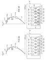
- the Fig. 2 represents an example of a usual diagram of the impedance of a coil in the impedance plane.
- Each point on the curve 21 represents a standardized impedance Z defined by a component normalized active R / L 0 ⁇ and a normalized reactive component L ⁇ / L 0 ⁇ (where R is the resistance of the coil, L is the inductance of the coil, L 0 is the inductance of the coil prior to installation, and ⁇ being the pulsation).
- the Fig. 3A represents the distribution of the standardized impedances Z from the coils according to their position on an initial structure 3a or reference having no defect.
- Each small circle on the curve 21 represents the impedance of a coil which depends in particular on the distance from the coil with respect to the edge 33 of the structure 3.
- the coils 511-516 installed at the edge 33 of the surface 3 present the highest impedances and those 531-536 which are furthest away from edge 33 have the lowest impedances.
- the small circles C1, C2, and C3 represent, starting from the edge 33, the coils 511-516 on the first row, the coils 521-526 on the second row, and the coils 531-536 on the third row respectively.
- the edge effect acts on each coil as a function of its distance from the edge 33.
- the edge 33 may be considered as an infinite section crack which prevents the eddy currents from circulating.
- a crack can be considered as an edge and therefore a coil in the vicinity of a crack has an impedance equivalent or rather comparable to that of a coil installed on the edge.
- the detection and monitoring of the progress of a crack can be achieved by measuring and comparing the electrical signal of each of the coils 511-536, compared to those which are in the border 511-516.
- the progress of a crack can be read by the appearance of a signal comparable to that of a coil at the edge and therefore can be classified in a category of "crack signal".
- the Fig. 3B represents the distribution of the signals from the coils according to their position on a structure 3b with defects.
- the coils of the edge 511, 512 and 515 which have cracks K1 and K2 in their neighborhoods have an impedance (represented by the small circle C11) higher than that (represented by the small circle C12) of coils 513 and 514 which have no cracks in their immediate vicinity.
- the second rank coils 521, 524 and 525 have an impedance (represented by the small circle C12) higher than that (represented by the small circle C13) of the coils 522 and 523.
- the impedance of the coils 531-536 of the third row is represented by the small circle C14.
- a crack or crack prevents eddy currents from flowing and therefore the impedance of a coil in the immediate vicinity of the crack will increase. Moreover, the effect of a crack is conjugated with the edge effect and consequently, the signals coming from, for example, two equidistant coils of the edge can only be differentiated by the existence of a crack in the immediate vicinity of one or the other of these two coils.
- the variation over time of the electrical signals coming from the coils can be analyzed by comparing these signals with detection thresholds which allow a direct diagnosis of defects or cracks in the structure 3.
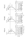
- Figs. 4A-4C represent a detection threshold S1 in the impedance plane that can be used to diagnose the presence of defects in the structure 3.
- the threshold S1 is used for the group of coils 521-526 installed in the second row.
- the processing means 11 are advantageously configured to analyze the electrical signals coming from the coils with respect to detection thresholds determined as a function of the positions of the coils on the surface 31.
- a detection threshold may correspond to each coil or each group of coils equidistant from the edge 33.
- the detection thresholds depend on the spatial distribution of the coils and in particular, their distance from the edge 33 of the surface 31. For example, the coils bordering are treated with a different threshold since from the beginning they have higher impedance levels due to the edge effect.
- the detection thresholds make it possible to determine whether the electrical signal levels of the coils are acceptable or not for the structure 3.
- the Fig. 4A illustrates the case of a structure 3a without defects and represents the detection threshold S1 corresponding to the coils 521-526 installed in the second row. According to this example, the signals (represented by the small circle C2) from these coils 521-526 are, of course, below the corresponding detection threshold S1.
- the Fig. 4B illustrates the case where the structure 3c has a few small cracks K11, K12 considered acceptable because the signals (represented by the small circle C23) from the coils 521-526 are still below the corresponding detection threshold S1 even if they get closer of this threshold.
- FIG. 4C illustrates the case where the cracks K1, K2 in the structure 3b are larger with signals (represented by the small circle C13) from the coils 521-526, which exceed the corresponding detection threshold S1. In the latter case, an alert is reported.
- the processing means 11 are configured to analyze the spatial distribution of the coils which have electrical signals whose levels are beyond the detection thresholds. This analysis makes it possible to check if these levels exceed another threshold of acceptability expressed in crack length in order to detect the lengths of cracks or cracks not to be exceeded.
- the processing means 11 are also configured to compare with each other the specific signals of the coils 511-516 installed at the edge 33 of the surface 31.
- This parallel analysis of all the coils 511-516 which are aligned at the edge of the structure 3 allows to cross the previous results to be even more sure of not having a false diagnosis. Indeed, this makes it possible to verify precisely whether the warning or the fault detection by the analysis of the variation of the electrical signals of the coils corresponds to a crack or a defect and not to a local change of the properties of the material. due for example to a thermal field, an electromagnetic field, a detachment of the coils of the surface, or any other external effect.
- edge crack is generally detected only by one or two edge coils and therefore a defect detected by a large number of edge coils can be considered suspect knowing that it is extremely unlikely to have as many cracks as reels.
- the processing means 11 are advantageously configured to determine a spatial mapping according to a C-scan type of report mode giving the respective positions of the coils detecting defects or cracks.
- This spatial mapping can be performed by establishing a correspondence between the electrical signal levels of the coils with respect to the edge effect in the impedance plane and the spatial distribution of these coils on the surface 31 of the structure 3.
- the means of visualization 91 can then visualize live this spatial map that determines the positions of cracks or defects in the structure.
- the coils 511-536 represented on the Figs 4A-4C and the corresponding signals (C1, C2, C3, C21, C22, C23, C24, C11, C12, C13, and C14) are hatched in the same manner. Note that in order to facilitate the diagnosis, the coils can be displayed on the display means 91 in different colors corresponding to different signal levels.
- the network comprises voluminal coils (for example, coils whose height is of the order of 5 mm)
- voluminal coils for example, coils whose height is of the order of 5 mm
- the processing means 11 are configured to determine the phases of the signals that have already been defined with respect to the edge effect.
- the processing means 11 analyze the phase shifts of the signals with respect to a reference phase corresponding to surface eddy currents.
- the surface eddy currents have a certain phase which can be considered as a reference phase, and the further down in the structure 3 the more the phase will be shifted with respect to the reference phase.
- a standard depth is defined by a phase shift of 57 ° with respect to the surface eddy currents and therefore a change of angle can be used to diagnose the position of a defect in the thickness of the structure 3.
- the phase shift of the signals gives an indication of the depth of a crack or the level where a defect is found in the structure 3. This is particularly advantageous in the case of a structure consisting of a stack of several layers to diagnose cracks that can for example start in an intermediate layer.
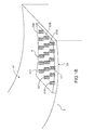
- Fig. 5 represents a section of the structure 3 comprising a first surface defect D1, a second defect D2 at depth, and a third defect D3 even more deeply.
- the small circles C31, C32, and C33 represent the signals coming from the coils detecting the defects D1, D2, and D3 respectively.
- the angle variations of the signals C31, C32, and C33 indicate the depth of the defects in the structure 3.
- control device 1 can be integrated into an aircraft health monitoring system.
- the diagnosis made by the control device can be consulted at a standstill or even continuously during operation of the structures of the aircraft. This makes it possible to enrich the monitoring of the health of the aircraft.
- the Fig. 6 represents a flowchart illustrating the different steps of the installation of the network 5 of coils on a structure 3 of the aircraft according to a particular embodiment of the invention.
- step E1 a molding tool is installed on the area of the surface 31 to be covered.
- step E2 a network 5 consisting of small coils associated in parallel in the molding tool and in contact with the surface 31 to be inspected of the structure 3 is mounted.
- step E3 the flexible filling material 17 (mastic) is poured into the molding tool and over the network of coils 5 to cover the coils while keeping them in contact with the surface 31. polymerization of the mastic, the latter also allows the adhesion of the network 5 of the coils on the metal skin (surface) of the structure 3.
- step E4 the coils are individually activated by a variable electrical generator.
- step E5 the electrical signals coming from the coils are taken by the measuring means 9.
- step E6 the processing means 11 determine the distribution in the impedance plane of the signals from the coils taking as a reference the edge effect.
- step E7 the processing means 11 perform an electronic diagnosis or self-calibration of the coils by analyzing the conformity of an electronic threshold of each of the coils. More particularly, the signals from the coils are analyzed with respect to the geometry of the structure. If the offset of the signals in the impedance plane is homogeneous (that is, if the coils positioned equidistant from the edge 33 have the same impedance levels), then it can be deduced that the coils work properly. On the other hand, if the offset of the signals is not homogeneous, then it can be deduced that there is at least one coil in the network which has been damaged during the installation. In the latter case, the network 5 is eventually removed to be repaired or replaced and the previous steps of installation are repeated.
- this analysis can be supplemented by a diagnosis based on the comparison of the electronic thresholds in time for possible detection of abnormal variation of the coil signal due to the initiation of breakage of a cable or of an electrical connection. If a coil has this type of anomaly, its signal will automatically be discarded.
- step E8 the processing means 11 record in the memory means 13 reference data corresponding to a signature of the individual signals of the coils forming the network 5 for future comparisons and diagnosis of good operation over time.
- the Fig. 7 represents a flowchart illustrating the different steps of the fault detection method according to a particular embodiment of the invention.
- the coils 511-536 are individually activated by the electric generator.
- the coils can be activated simultaneously or in a virtual scanning mode of the surface 31 by sequences of a determined number of coils comprising at least one edge coil at each sequence.
- step E22 the processing means 11 record in the memory means 13 initial data corresponding to initial signals of the coils.
- step E23 the processing means 11 compare the initial data with the reference data to determine the variation over time of the electrical signal of each of the coils taking the edge effect as a reference. If for a given coil the variation exceeds a determined value, then it can be deduced that the coil detects a fault. This can be confirmed when there are two or more neighboring coils that also indicate variations above specific values.
- step E24 the processing means 11 compare the signals of the coils installed at the edge 33 of the surface 31 with one another. This makes it possible to cross the previous results to verify that the detection corresponds to a crack or a defect and does not is not a false alarm.
- the memory means 13 may comprise a computer program comprising code instructions adapted to the implementation of the method according to the invention as described above when it is executed by the means of treatment 11.
Landscapes
- Chemical & Material Sciences (AREA)
- Chemical Kinetics & Catalysis (AREA)
- Electrochemistry (AREA)
- Physics & Mathematics (AREA)
- Health & Medical Sciences (AREA)
- Life Sciences & Earth Sciences (AREA)
- Analytical Chemistry (AREA)
- Biochemistry (AREA)
- General Health & Medical Sciences (AREA)
- General Physics & Mathematics (AREA)
- Immunology (AREA)
- Pathology (AREA)
- Investigating Or Analyzing Materials By The Use Of Magnetic Means (AREA)
Applications Claiming Priority (1)
| Application Number | Priority Date | Filing Date | Title |
|---|---|---|---|
| FR1057643A FR2965356A1 (fr) | 2010-09-23 | 2010-09-23 | Controle non destructif d'une structure dans un aeronef |
Publications (3)
| Publication Number | Publication Date |
|---|---|
| EP2434280A2 true EP2434280A2 (de) | 2012-03-28 |
| EP2434280A3 EP2434280A3 (de) | 2012-05-09 |
| EP2434280B1 EP2434280B1 (de) | 2016-12-07 |
Family
ID=43837308
Family Applications (1)
| Application Number | Title | Priority Date | Filing Date |
|---|---|---|---|
| EP11182121.1A Not-in-force EP2434280B1 (de) | 2010-09-23 | 2011-09-21 | Zerstörungsfreie Prüfung einer Struktur in einem Flugzeug |
Country Status (4)
| Country | Link |
|---|---|
| US (1) | US8988071B2 (de) |
| EP (1) | EP2434280B1 (de) |
| CN (1) | CN102565186B (de) |
| FR (1) | FR2965356A1 (de) |
Families Citing this family (11)
| Publication number | Priority date | Publication date | Assignee | Title |
|---|---|---|---|---|
| US9804111B2 (en) * | 2013-01-14 | 2017-10-31 | Proceq Sa | Impedance-based measurement device with a two-dimensional array of coils |
| EP2846280A1 (de) * | 2013-09-06 | 2015-03-11 | Airbus Operations | Simulation von Dehnungsmessstreifen |
| US9349516B2 (en) * | 2014-02-13 | 2016-05-24 | Siemens Energy, Inc. | Multidirectional magnetic particle inspection system |
| CN104267096A (zh) * | 2014-09-27 | 2015-01-07 | 广东科学技术职业学院 | 管坯铸造缺陷无损检测方法及装置 |
| CN105891323A (zh) * | 2014-11-21 | 2016-08-24 | 中机生产力促进中心 | 一种检测管道变形的涡流探头阵列 |
| DE102016113081A1 (de) * | 2016-07-15 | 2018-01-18 | Rohmann Gmbh | Wirbelstromprüfung mit Impulsmagnetisierung auf einem weiten Prüffeld |
| CN106568836A (zh) * | 2016-11-08 | 2017-04-19 | 上海航天精密机械研究所 | 一种用于导电材料快速精确检测的柔性涡流阵列探头 |
| DE102017107708A1 (de) | 2017-04-10 | 2018-10-11 | Prüftechnik Dieter Busch AG | Differenzsonde, Prüfvorrichtung und Herstellungsverfahren |
| WO2019199894A1 (en) * | 2018-04-09 | 2019-10-17 | Jentek Sensors, Inc. | Complex part inspection with eddy current sensors |
| CN110646506B (zh) * | 2019-09-21 | 2023-04-07 | 北京嘉盛智检科技有限公司 | 一种叶片凸台缺陷原位检测方法 |
| CN116587776B (zh) * | 2023-03-10 | 2026-01-09 | 大连理工大学 | 一种基于电磁传感阵列的轮胎扎钉监测装置 |
Citations (1)
| Publication number | Priority date | Publication date | Assignee | Title |
|---|---|---|---|---|
| EP2037261A1 (de) | 2007-09-11 | 2009-03-18 | Olympus NDT | Phasenscan-Wirbelstromsonde und Phasenscanverfahren, die eine vollständige und kontinuierliche Abdeckung einer Testoberfläche ohne mechanisches Scannen bereitstellen |
Family Cites Families (17)
| Publication number | Priority date | Publication date | Assignee | Title |
|---|---|---|---|---|
| SU700830A1 (ru) * | 1978-06-08 | 1979-11-30 | Кубанский Ордена Трудового Красного Знамени Сельскохозяйственный Институт | Токовихревой накладной преобразователь |
| US5623204A (en) * | 1993-05-17 | 1997-04-22 | Wilkerson; Brian | Eddy current probe |
| US6414483B1 (en) * | 2000-07-27 | 2002-07-02 | General Electric Company | Eddy current inspection method and apparatus for detecting flaws in an electrically conductive component |
| US7183764B2 (en) * | 2000-09-12 | 2007-02-27 | Jentek Sensors, Inc. | Method for inspecting a channel using a flexible sensor |
| US6992482B2 (en) * | 2000-11-08 | 2006-01-31 | Jentek Sensors, Inc. | Magnetic field sensor having a switchable drive current spatial distribution |
| US7385392B2 (en) * | 2000-11-13 | 2008-06-10 | Jentek Sensors, Inc. | Eddy current sensing arrays and system |
| US6784662B2 (en) * | 2001-03-19 | 2004-08-31 | Jentek Sensors, Inc. | Eddy current sensor arrays having drive windings with extended portions |
| US6720775B2 (en) * | 2001-06-12 | 2004-04-13 | General Electric Company | Pulsed eddy current two-dimensional sensor array inspection probe and system |
| US20040004475A1 (en) * | 2002-04-22 | 2004-01-08 | Jentek Sensors, Inc. | High throughput absolute flaw imaging |
| US7015690B2 (en) * | 2004-05-27 | 2006-03-21 | General Electric Company | Omnidirectional eddy current probe and inspection system |
| US7250757B1 (en) * | 2004-09-16 | 2007-07-31 | Radiation Monitoring Devices, Inc. | Apparatus and method for circuit analysis using magnetic and electromagnetic stimulation of the circuit for dual magnetic field imaging |
| US7528598B2 (en) * | 2005-06-22 | 2009-05-05 | Jentek Sensors, Inc. | Fastener and fitting based sensing methods |
| JP5175513B2 (ja) * | 2007-09-20 | 2013-04-03 | 株式会社原子力エンジニアリング | 渦流探傷方法、渦流探傷装置及び渦流探傷プローブ |
| US7888932B2 (en) * | 2007-11-05 | 2011-02-15 | General Electric Company | Surface flaw detection system to facilitate nondestructive inspection of a component and methods of assembling the same |
| JP2009216559A (ja) * | 2008-03-11 | 2009-09-24 | Hitachi-Ge Nuclear Energy Ltd | 渦電流検査装置 |
| US8018228B2 (en) * | 2008-06-13 | 2011-09-13 | Olympus Ndt | High resolution and flexible eddy current array probe |
| US8164328B2 (en) * | 2008-07-01 | 2012-04-24 | The United States Of America As Represented By The Administrator Of The National Aeronautics And Space Administration | Eddy current system and method for crack detection |
-
2010
- 2010-09-23 FR FR1057643A patent/FR2965356A1/fr not_active Withdrawn
-
2011
- 2011-09-02 US US13/224,586 patent/US8988071B2/en not_active Expired - Fee Related
- 2011-09-21 EP EP11182121.1A patent/EP2434280B1/de not_active Not-in-force
- 2011-09-23 CN CN201110299558.0A patent/CN102565186B/zh not_active Expired - Fee Related
Patent Citations (1)
| Publication number | Priority date | Publication date | Assignee | Title |
|---|---|---|---|---|
| EP2037261A1 (de) | 2007-09-11 | 2009-03-18 | Olympus NDT | Phasenscan-Wirbelstromsonde und Phasenscanverfahren, die eine vollständige und kontinuierliche Abdeckung einer Testoberfläche ohne mechanisches Scannen bereitstellen |
Also Published As
| Publication number | Publication date |
|---|---|
| FR2965356A1 (fr) | 2012-03-30 |
| EP2434280A3 (de) | 2012-05-09 |
| CN102565186A (zh) | 2012-07-11 |
| US8988071B2 (en) | 2015-03-24 |
| CN102565186B (zh) | 2016-07-06 |
| EP2434280B1 (de) | 2016-12-07 |
| US20120074932A1 (en) | 2012-03-29 |
Similar Documents
| Publication | Publication Date | Title |
|---|---|---|
| EP2434280B1 (de) | Zerstörungsfreie Prüfung einer Struktur in einem Flugzeug | |
| EP2979082B1 (de) | Verfahren und system zur erkennung von defekten auf einem objekt | |
| EP3707503B1 (de) | Überwachung der strukturellen gesundheit für eine industriestruktur | |
| EP1850088B1 (de) | Messung von Wanddicken, insbesondere von Laufradschaufeln, mit Hilfe von Wirbelströmen | |
| US10001457B2 (en) | Performance curve generation for non-destructive testing sensors | |
| FR2854954A1 (fr) | Imagerie de defaut absolue a haute capacite | |
| FR3006447A1 (fr) | Procede d'inspection par transmission d'ultrasons ameliore | |
| EP3491400B1 (de) | Verfahren und system zum lokalisieren von defekten an einem elektrischen kabel | |
| FR2980850A1 (fr) | Procede et systeme de diagnotic de l'etat interne d'une batterie par emission acoustique. | |
| EP3660484B1 (de) | System und verfahren zur bestimmung der eigenschaften eines risses | |
| CN114235962A (zh) | 一种面向各向异性结构的超声导波成像方法及系统 | |
| FR3113130A1 (fr) | Système de contrôle de la corrosion dans des structures métalliques par ondes guidées ultrasonores | |
| EP3298419B1 (de) | Verfahren zur analyse eines kabels mit einem verarbeitungsvorgang zur verstärkung der signatur eines leichten fehlers | |
| FR2825800A1 (fr) | Procede et systeme pour determiner et quantifier les defauts dus a la corrosion sur et dans les composants metalliques | |
| FR3090106A1 (fr) | Procédé et dispositif pour détecter un évènement d’impact et véhicule associé | |
| CN119164969B (zh) | 一种超洁净环境下的晶圆质量检测方法 | |
| CN106645401B (zh) | 一种基于频率波数估计的损伤定位与重构方法及系统 | |
| FR3062481A1 (fr) | Dispositif et procede electromagnetique de detection de defauts | |
| FR2994744A1 (fr) | Dispositif d'evaluation et systeme de controle d'amenagements de cellules electrochimiques | |
| EP0209476A2 (de) | Verfahren und Vorrichtung zur Feststellung des Auftretens und zur Quantifizierung der Entwicklung von Rissen auf der Oberfläche eines Materials | |
| FR3003953A1 (fr) | Systeme de detection de defauts par ultrasons sur un element tournant d'un moteur d'aeronef | |
| WO2025146422A1 (fr) | Procédé de contrôle non destructif de conformité d'une pièce composée de matériau conducteur, dispositif, système et programme d'ordinateur correspondant | |
| CN121253660A (zh) | 一种陶瓷胶粘剂寿命智能监测系统及方法 | |
| FR3093795A1 (fr) | Procédé de génération d’un indice de POD | |
| FR3003952A1 (fr) | Systeme de detection de defauts sur un objet |
Legal Events
| Date | Code | Title | Description |
|---|---|---|---|
| PUAI | Public reference made under article 153(3) epc to a published international application that has entered the european phase |
Free format text: ORIGINAL CODE: 0009012 |
|
| AK | Designated contracting states |
Kind code of ref document: A2 Designated state(s): AL AT BE BG CH CY CZ DE DK EE ES FI FR GB GR HR HU IE IS IT LI LT LU LV MC MK MT NL NO PL PT RO RS SE SI SK SM TR |
|
| AX | Request for extension of the european patent |
Extension state: BA ME |
|
| PUAL | Search report despatched |
Free format text: ORIGINAL CODE: 0009013 |
|
| RIC1 | Information provided on ipc code assigned before grant |
Ipc: G01N 27/90 20060101AFI20120329BHEP |
|
| AK | Designated contracting states |
Kind code of ref document: A3 Designated state(s): AL AT BE BG CH CY CZ DE DK EE ES FI FR GB GR HR HU IE IS IT LI LT LU LV MC MK MT NL NO PL PT RO RS SE SI SK SM TR |
|
| AX | Request for extension of the european patent |
Extension state: BA ME |
|
| RIC1 | Information provided on ipc code assigned before grant |
Ipc: G01N 27/90 20060101AFI20120405BHEP |
|
| 17P | Request for examination filed |
Effective date: 20121031 |
|
| GRAP | Despatch of communication of intention to grant a patent |
Free format text: ORIGINAL CODE: EPIDOSNIGR1 |
|
| RIC1 | Information provided on ipc code assigned before grant |
Ipc: G01N 27/90 20060101AFI20160714BHEP |
|
| INTG | Intention to grant announced |
Effective date: 20160810 |
|
| GRAS | Grant fee paid |
Free format text: ORIGINAL CODE: EPIDOSNIGR3 |
|
| GRAA | (expected) grant |
Free format text: ORIGINAL CODE: 0009210 |
|
| AK | Designated contracting states |
Kind code of ref document: B1 Designated state(s): AL AT BE BG CH CY CZ DE DK EE ES FI FR GB GR HR HU IE IS IT LI LT LU LV MC MK MT NL NO PL PT RO RS SE SI SK SM TR |
|
| REG | Reference to a national code |
Ref country code: GB Ref legal event code: FG4D Free format text: NOT ENGLISH |
|
| REG | Reference to a national code |
Ref country code: CH Ref legal event code: EP Ref country code: AT Ref legal event code: REF Ref document number: 852188 Country of ref document: AT Kind code of ref document: T Effective date: 20161215 |
|
| REG | Reference to a national code |
Ref country code: IE Ref legal event code: FG4D Free format text: LANGUAGE OF EP DOCUMENT: FRENCH |
|
| REG | Reference to a national code |
Ref country code: DE Ref legal event code: R096 Ref document number: 602011033076 Country of ref document: DE |
|
| PG25 | Lapsed in a contracting state [announced via postgrant information from national office to epo] |
Ref country code: LV Free format text: LAPSE BECAUSE OF FAILURE TO SUBMIT A TRANSLATION OF THE DESCRIPTION OR TO PAY THE FEE WITHIN THE PRESCRIBED TIME-LIMIT Effective date: 20161207 |
|
| REG | Reference to a national code |
Ref country code: LT Ref legal event code: MG4D |
|
| REG | Reference to a national code |
Ref country code: NL Ref legal event code: MP Effective date: 20161207 |
|
| PG25 | Lapsed in a contracting state [announced via postgrant information from national office to epo] |
Ref country code: NO Free format text: LAPSE BECAUSE OF FAILURE TO SUBMIT A TRANSLATION OF THE DESCRIPTION OR TO PAY THE FEE WITHIN THE PRESCRIBED TIME-LIMIT Effective date: 20170307 Ref country code: GR Free format text: LAPSE BECAUSE OF FAILURE TO SUBMIT A TRANSLATION OF THE DESCRIPTION OR TO PAY THE FEE WITHIN THE PRESCRIBED TIME-LIMIT Effective date: 20170308 Ref country code: SE Free format text: LAPSE BECAUSE OF FAILURE TO SUBMIT A TRANSLATION OF THE DESCRIPTION OR TO PAY THE FEE WITHIN THE PRESCRIBED TIME-LIMIT Effective date: 20161207 Ref country code: LT Free format text: LAPSE BECAUSE OF FAILURE TO SUBMIT A TRANSLATION OF THE DESCRIPTION OR TO PAY THE FEE WITHIN THE PRESCRIBED TIME-LIMIT Effective date: 20161207 |
|
| REG | Reference to a national code |
Ref country code: AT Ref legal event code: MK05 Ref document number: 852188 Country of ref document: AT Kind code of ref document: T Effective date: 20161207 |
|
| PG25 | Lapsed in a contracting state [announced via postgrant information from national office to epo] |
Ref country code: RS Free format text: LAPSE BECAUSE OF FAILURE TO SUBMIT A TRANSLATION OF THE DESCRIPTION OR TO PAY THE FEE WITHIN THE PRESCRIBED TIME-LIMIT Effective date: 20161207 Ref country code: ES Free format text: LAPSE BECAUSE OF FAILURE TO SUBMIT A TRANSLATION OF THE DESCRIPTION OR TO PAY THE FEE WITHIN THE PRESCRIBED TIME-LIMIT Effective date: 20161207 Ref country code: FI Free format text: LAPSE BECAUSE OF FAILURE TO SUBMIT A TRANSLATION OF THE DESCRIPTION OR TO PAY THE FEE WITHIN THE PRESCRIBED TIME-LIMIT Effective date: 20161207 Ref country code: HR Free format text: LAPSE BECAUSE OF FAILURE TO SUBMIT A TRANSLATION OF THE DESCRIPTION OR TO PAY THE FEE WITHIN THE PRESCRIBED TIME-LIMIT Effective date: 20161207 |
|
| PG25 | Lapsed in a contracting state [announced via postgrant information from national office to epo] |
Ref country code: NL Free format text: LAPSE BECAUSE OF FAILURE TO SUBMIT A TRANSLATION OF THE DESCRIPTION OR TO PAY THE FEE WITHIN THE PRESCRIBED TIME-LIMIT Effective date: 20161207 |
|
| PG25 | Lapsed in a contracting state [announced via postgrant information from national office to epo] |
Ref country code: EE Free format text: LAPSE BECAUSE OF FAILURE TO SUBMIT A TRANSLATION OF THE DESCRIPTION OR TO PAY THE FEE WITHIN THE PRESCRIBED TIME-LIMIT Effective date: 20161207 Ref country code: IS Free format text: LAPSE BECAUSE OF FAILURE TO SUBMIT A TRANSLATION OF THE DESCRIPTION OR TO PAY THE FEE WITHIN THE PRESCRIBED TIME-LIMIT Effective date: 20170407 Ref country code: RO Free format text: LAPSE BECAUSE OF FAILURE TO SUBMIT A TRANSLATION OF THE DESCRIPTION OR TO PAY THE FEE WITHIN THE PRESCRIBED TIME-LIMIT Effective date: 20161207 Ref country code: CZ Free format text: LAPSE BECAUSE OF FAILURE TO SUBMIT A TRANSLATION OF THE DESCRIPTION OR TO PAY THE FEE WITHIN THE PRESCRIBED TIME-LIMIT Effective date: 20161207 Ref country code: SK Free format text: LAPSE BECAUSE OF FAILURE TO SUBMIT A TRANSLATION OF THE DESCRIPTION OR TO PAY THE FEE WITHIN THE PRESCRIBED TIME-LIMIT Effective date: 20161207 |
|
| PG25 | Lapsed in a contracting state [announced via postgrant information from national office to epo] |
Ref country code: PL Free format text: LAPSE BECAUSE OF FAILURE TO SUBMIT A TRANSLATION OF THE DESCRIPTION OR TO PAY THE FEE WITHIN THE PRESCRIBED TIME-LIMIT Effective date: 20161207 Ref country code: BG Free format text: LAPSE BECAUSE OF FAILURE TO SUBMIT A TRANSLATION OF THE DESCRIPTION OR TO PAY THE FEE WITHIN THE PRESCRIBED TIME-LIMIT Effective date: 20170307 Ref country code: PT Free format text: LAPSE BECAUSE OF FAILURE TO SUBMIT A TRANSLATION OF THE DESCRIPTION OR TO PAY THE FEE WITHIN THE PRESCRIBED TIME-LIMIT Effective date: 20170407 Ref country code: SM Free format text: LAPSE BECAUSE OF FAILURE TO SUBMIT A TRANSLATION OF THE DESCRIPTION OR TO PAY THE FEE WITHIN THE PRESCRIBED TIME-LIMIT Effective date: 20161207 Ref country code: IT Free format text: LAPSE BECAUSE OF FAILURE TO SUBMIT A TRANSLATION OF THE DESCRIPTION OR TO PAY THE FEE WITHIN THE PRESCRIBED TIME-LIMIT Effective date: 20161207 Ref country code: AT Free format text: LAPSE BECAUSE OF FAILURE TO SUBMIT A TRANSLATION OF THE DESCRIPTION OR TO PAY THE FEE WITHIN THE PRESCRIBED TIME-LIMIT Effective date: 20161207 |
|
| REG | Reference to a national code |
Ref country code: DE Ref legal event code: R097 Ref document number: 602011033076 Country of ref document: DE |
|
| REG | Reference to a national code |
Ref country code: FR Ref legal event code: PLFP Year of fee payment: 7 |
|
| PLBE | No opposition filed within time limit |
Free format text: ORIGINAL CODE: 0009261 |
|
| STAA | Information on the status of an ep patent application or granted ep patent |
Free format text: STATUS: NO OPPOSITION FILED WITHIN TIME LIMIT |
|
| 26N | No opposition filed |
Effective date: 20170908 |
|
| PG25 | Lapsed in a contracting state [announced via postgrant information from national office to epo] |
Ref country code: DK Free format text: LAPSE BECAUSE OF FAILURE TO SUBMIT A TRANSLATION OF THE DESCRIPTION OR TO PAY THE FEE WITHIN THE PRESCRIBED TIME-LIMIT Effective date: 20161207 Ref country code: SI Free format text: LAPSE BECAUSE OF FAILURE TO SUBMIT A TRANSLATION OF THE DESCRIPTION OR TO PAY THE FEE WITHIN THE PRESCRIBED TIME-LIMIT Effective date: 20161207 |
|
| REG | Reference to a national code |
Ref country code: CH Ref legal event code: PL |
|
| PG25 | Lapsed in a contracting state [announced via postgrant information from national office to epo] |
Ref country code: MC Free format text: LAPSE BECAUSE OF FAILURE TO SUBMIT A TRANSLATION OF THE DESCRIPTION OR TO PAY THE FEE WITHIN THE PRESCRIBED TIME-LIMIT Effective date: 20161207 |
|
| REG | Reference to a national code |
Ref country code: IE Ref legal event code: MM4A |
|
| REG | Reference to a national code |
Ref country code: BE Ref legal event code: MM Effective date: 20170930 |
|
| PG25 | Lapsed in a contracting state [announced via postgrant information from national office to epo] |
Ref country code: LU Free format text: LAPSE BECAUSE OF NON-PAYMENT OF DUE FEES Effective date: 20170921 |
|
| PG25 | Lapsed in a contracting state [announced via postgrant information from national office to epo] |
Ref country code: LI Free format text: LAPSE BECAUSE OF NON-PAYMENT OF DUE FEES Effective date: 20170930 Ref country code: IE Free format text: LAPSE BECAUSE OF NON-PAYMENT OF DUE FEES Effective date: 20170921 Ref country code: CH Free format text: LAPSE BECAUSE OF NON-PAYMENT OF DUE FEES Effective date: 20170930 |
|
| PG25 | Lapsed in a contracting state [announced via postgrant information from national office to epo] |
Ref country code: BE Free format text: LAPSE BECAUSE OF NON-PAYMENT OF DUE FEES Effective date: 20170930 |
|
| REG | Reference to a national code |
Ref country code: FR Ref legal event code: PLFP Year of fee payment: 8 |
|
| PG25 | Lapsed in a contracting state [announced via postgrant information from national office to epo] |
Ref country code: MT Free format text: LAPSE BECAUSE OF FAILURE TO SUBMIT A TRANSLATION OF THE DESCRIPTION OR TO PAY THE FEE WITHIN THE PRESCRIBED TIME-LIMIT Effective date: 20161207 |
|
| PG25 | Lapsed in a contracting state [announced via postgrant information from national office to epo] |
Ref country code: HU Free format text: LAPSE BECAUSE OF FAILURE TO SUBMIT A TRANSLATION OF THE DESCRIPTION OR TO PAY THE FEE WITHIN THE PRESCRIBED TIME-LIMIT; INVALID AB INITIO Effective date: 20110921 |
|
| PG25 | Lapsed in a contracting state [announced via postgrant information from national office to epo] |
Ref country code: CY Free format text: LAPSE BECAUSE OF NON-PAYMENT OF DUE FEES Effective date: 20161207 |
|
| PGFP | Annual fee paid to national office [announced via postgrant information from national office to epo] |
Ref country code: DE Payment date: 20190918 Year of fee payment: 9 |
|
| PG25 | Lapsed in a contracting state [announced via postgrant information from national office to epo] |
Ref country code: MK Free format text: LAPSE BECAUSE OF FAILURE TO SUBMIT A TRANSLATION OF THE DESCRIPTION OR TO PAY THE FEE WITHIN THE PRESCRIBED TIME-LIMIT Effective date: 20161207 |
|
| PG25 | Lapsed in a contracting state [announced via postgrant information from national office to epo] |
Ref country code: TR Free format text: LAPSE BECAUSE OF FAILURE TO SUBMIT A TRANSLATION OF THE DESCRIPTION OR TO PAY THE FEE WITHIN THE PRESCRIBED TIME-LIMIT Effective date: 20161207 |
|
| PG25 | Lapsed in a contracting state [announced via postgrant information from national office to epo] |
Ref country code: AL Free format text: LAPSE BECAUSE OF FAILURE TO SUBMIT A TRANSLATION OF THE DESCRIPTION OR TO PAY THE FEE WITHIN THE PRESCRIBED TIME-LIMIT Effective date: 20161207 |
|
| REG | Reference to a national code |
Ref country code: DE Ref legal event code: R119 Ref document number: 602011033076 Country of ref document: DE |
|
| PG25 | Lapsed in a contracting state [announced via postgrant information from national office to epo] |
Ref country code: DE Free format text: LAPSE BECAUSE OF NON-PAYMENT OF DUE FEES Effective date: 20210401 |
|
| PGFP | Annual fee paid to national office [announced via postgrant information from national office to epo] |
Ref country code: FR Payment date: 20210921 Year of fee payment: 11 |
|
| PGFP | Annual fee paid to national office [announced via postgrant information from national office to epo] |
Ref country code: GB Payment date: 20210920 Year of fee payment: 11 |
|
| GBPC | Gb: european patent ceased through non-payment of renewal fee |
Effective date: 20220921 |
|
| PG25 | Lapsed in a contracting state [announced via postgrant information from national office to epo] |
Ref country code: FR Free format text: LAPSE BECAUSE OF NON-PAYMENT OF DUE FEES Effective date: 20220930 |
|
| PG25 | Lapsed in a contracting state [announced via postgrant information from national office to epo] |
Ref country code: GB Free format text: LAPSE BECAUSE OF NON-PAYMENT OF DUE FEES Effective date: 20220921 |