EP2434457A1 - Verfahren zur ausgabe von bildinformationen - Google Patents
Verfahren zur ausgabe von bildinformationen Download PDFInfo
- Publication number
- EP2434457A1 EP2434457A1 EP10777735A EP10777735A EP2434457A1 EP 2434457 A1 EP2434457 A1 EP 2434457A1 EP 10777735 A EP10777735 A EP 10777735A EP 10777735 A EP10777735 A EP 10777735A EP 2434457 A1 EP2434457 A1 EP 2434457A1
- Authority
- EP
- European Patent Office
- Prior art keywords
- image
- road
- photographic
- image data
- data
- Prior art date
- Legal status (The legal status is an assumption and is not a legal conclusion. Google has not performed a legal analysis and makes no representation as to the accuracy of the status listed.)
- Withdrawn
Links
Images




























Classifications
-
- H—ELECTRICITY
- H04—ELECTRIC COMMUNICATION TECHNIQUE
- H04N—PICTORIAL COMMUNICATION, e.g. TELEVISION
- H04N13/00—Stereoscopic video systems; Multi-view video systems; Details thereof
- H04N13/20—Image signal generators
- H04N13/204—Image signal generators using stereoscopic image cameras
-
- G—PHYSICS
- G06—COMPUTING OR CALCULATING; COUNTING
- G06T—IMAGE DATA PROCESSING OR GENERATION, IN GENERAL
- G06T15/00—Three-dimensional [3D] image rendering
- G06T15/10—Geometric effects
- G06T15/20—Perspective computation
- G06T15/205—Image-based rendering
-
- G—PHYSICS
- G01—MEASURING; TESTING
- G01C—MEASURING DISTANCES, LEVELS OR BEARINGS; SURVEYING; NAVIGATION; GYROSCOPIC INSTRUMENTS; PHOTOGRAMMETRY OR VIDEOGRAMMETRY
- G01C11/00—Photogrammetry or videogrammetry, e.g. stereogrammetry; Photographic surveying
- G01C11/02—Picture taking arrangements specially adapted for photogrammetry or photographic surveying, e.g. controlling overlapping of pictures
-
- G—PHYSICS
- G06—COMPUTING OR CALCULATING; COUNTING
- G06F—ELECTRIC DIGITAL DATA PROCESSING
- G06F16/00—Information retrieval; Database structures therefor; File system structures therefor
- G06F16/50—Information retrieval; Database structures therefor; File system structures therefor of still image data
- G06F16/56—Information retrieval; Database structures therefor; File system structures therefor of still image data having vectorial format
-
- G—PHYSICS
- G06—COMPUTING OR CALCULATING; COUNTING
- G06F—ELECTRIC DIGITAL DATA PROCESSING
- G06F16/00—Information retrieval; Database structures therefor; File system structures therefor
- G06F16/70—Information retrieval; Database structures therefor; File system structures therefor of video data
-
- G—PHYSICS
- G06—COMPUTING OR CALCULATING; COUNTING
- G06F—ELECTRIC DIGITAL DATA PROCESSING
- G06F16/00—Information retrieval; Database structures therefor; File system structures therefor
- G06F16/70—Information retrieval; Database structures therefor; File system structures therefor of video data
- G06F16/73—Querying
- G06F16/732—Query formulation
- G06F16/7335—Graphical querying, e.g. query-by-region, query-by-sketch, query-by-trajectory, GUIs for designating a person/face/object as a query predicate
-
- G—PHYSICS
- G06—COMPUTING OR CALCULATING; COUNTING
- G06F—ELECTRIC DIGITAL DATA PROCESSING
- G06F16/00—Information retrieval; Database structures therefor; File system structures therefor
- G06F16/70—Information retrieval; Database structures therefor; File system structures therefor of video data
- G06F16/78—Retrieval characterised by using metadata, e.g. metadata not derived from the content or metadata generated manually
- G06F16/783—Retrieval characterised by using metadata, e.g. metadata not derived from the content or metadata generated manually using metadata automatically derived from the content
- G06F16/7837—Retrieval characterised by using metadata, e.g. metadata not derived from the content or metadata generated manually using metadata automatically derived from the content using objects detected or recognised in the video content
- G06F16/784—Retrieval characterised by using metadata, e.g. metadata not derived from the content or metadata generated manually using metadata automatically derived from the content using objects detected or recognised in the video content the detected or recognised objects being people
-
- G—PHYSICS
- G06—COMPUTING OR CALCULATING; COUNTING
- G06T—IMAGE DATA PROCESSING OR GENERATION, IN GENERAL
- G06T17/00—Three-dimensional [3D] modelling for computer graphics
- G06T17/05—Geographic models
-
- G—PHYSICS
- G06—COMPUTING OR CALCULATING; COUNTING
- G06T—IMAGE DATA PROCESSING OR GENERATION, IN GENERAL
- G06T19/00—Manipulating three-dimensional [3D] models or images for computer graphics
- G06T19/003—Navigation within 3D models or images
-
- H—ELECTRICITY
- H04—ELECTRIC COMMUNICATION TECHNIQUE
- H04N—PICTORIAL COMMUNICATION, e.g. TELEVISION
- H04N9/00—Details of colour television systems
- H04N9/79—Processing of colour television signals in connection with recording
- H04N9/80—Transformation of the television signal for recording, e.g. modulation, frequency changing; Inverse transformation for playback
- H04N9/82—Transformation of the television signal for recording, e.g. modulation, frequency changing; Inverse transformation for playback the individual colour picture signal components being recorded simultaneously only
- H04N9/8205—Transformation of the television signal for recording, e.g. modulation, frequency changing; Inverse transformation for playback the individual colour picture signal components being recorded simultaneously only involving the multiplexing of an additional signal and the colour video signal
-
- G—PHYSICS
- G06—COMPUTING OR CALCULATING; COUNTING
- G06T—IMAGE DATA PROCESSING OR GENERATION, IN GENERAL
- G06T2210/00—Indexing scheme for image generation or computer graphics
- G06T2210/44—Morphing
Definitions
- the present invention is related to a method of generating and outputting image information.
- the present invention is related to a system and a method of generating video image information, wherein a three dimensional image of above ground landscape including urban areas using aerial photographs taken from the sky by an aircraft or photographs taken above ground at street level is generated, and the present invention is also related to a system and a method of generating image information wherein a video picture of three dimensional city landscapes using photographs taken from various angles above ground is generated.
- (2) is a method in which a process of calculating three dimensional coordinates in advance using a usual survey by photo is calculated each time a combination of the panoramic photographs which are used changes and is merely postponing the calculation, and load at the time of display becomes much larger compared to conventional CG technology.
- Patent Document 5 discloses a midair entertainment system via the internet using aerial photographs and includes features such as the ability to add building data, the method consistently uses [three dimensional object data which is applied and generated with a stereo process is performed on photographic data] or [three dimensional object data] of a building which is changed by a changing means, which is a fundamentally different technology to the present invention. While there is also a method which uses processing of land surface images taken by a satellite as in Ace combat of ACECOMBAT described in Non Patent Document 1, in the end the purpose of this method is to bring about a sense of reality to games and does not always match actual three dimensional landscapes.
- Non Patent Document 2 city space three dimensional simulated vision which can be seen in Second Life of Non Patent Document 2 displays virtual cities in three dimensions which are not compatible with actual maps. While there is meet-me using COCOR of MMET-ME described in Non Patent Document 3, which is a three dimensional image generation and entertainment system of virtual city spaces compatible with actual maps for displaying city spaces more realistically compared to Second Life, it does not match reality in terms of exterior wall landscape and detailed structure of buildings.
- the technology of the present invention accumulates a large amount of multi-view point and multi-directional aerial photographs taken in advance, and the conventional technology for obtaining aerial photographs uses a digital format one dimensional line sensor from an analog camera type aerial camera owing to recent rapid process in digital technology or an aerial photographic camera using two dimensional video elements.
- Patent Document 1 A system for creating Ortho images from oblique photographs taken using a digital camera and dedicated software is proposed in Patent Document 1.
- the coordinates of a geographical feature are calculated by setting ground reference points in advance and calculating the camera position and orientation by referring to these reference points in an aerial photograph of a desired survey, it is possible to equip an aircraft with GPS (Global Positioning System) and IMU (Inertial Measurement Unit) and measure the camera position and orientation at the time of taking the image (Patent Document 2).
- GPS Global Positioning System
- IMU Inertial Measurement Unit
- Non Patent Document 1 is a three dimensional visual data generation and browsing system which pursues realism using high resolution satellite imagery as a landscape material, because the object is a foreign war zone and the mage itself is not updated from the time it is created, it is different to the an actual three dimensional image of a city landscape.
- the system which is proposed in Non Patent Document 2 displays three dimensional images of city landscapes at human sight line but the entire display is a fake world generated on a computer which is different to the actual world and does not attempt to display a three dimensional city landscape which strives for realism.
- the method of Non Patent Document 3 adds improvements to the method of Non Patent Document 2 by constructing buildings corresponding to an actual city map yet as a landscape does not strive for uniformity with reality.
- Patent Document 2 is related to obtaining aerial photographs. Two oblique images are obtained in the system proposed in Patent Document 2, however it is difficult to obtain a large amount of multi-directional high density images which are required by the present invention with only a single oblique image.
- the system which is proposed in Patent Document 3 takes images using CDD line sensors in three different directions and because these three CDD line sensors are arranged in parallel and in a straight line, the system is suitable for obtaining survey use stereo images, but the amount of data is severely lacking for obtaining original images for generating three dimensional images of city landscapes which is the object of the present invention.
- the present invention has been invented as a result of attempting to overcome the problems described above.
- a system configured to photograph in a large range a plurality of images in multi-direction at mesh points in high density and in air by aircrafts, by storing these lots of images being as a database the system being configured to fast search images which have the little disparities in the case when seen from an arbitrary direction at an arbitrary point of a city, and moreover a morphing system is provided the morphing system generating a smooth continuous video from images which has the little disparities corresponding a specified view point, sight direction, and position in the city.
- a system is provided, the system being specialized for being mounted on a vehicle for obtaining images in all directions on a road or a passage way in a city in order to generate a real video at a human eye level also on ground, by storing a lot of images obtained as a database the system being configured to fast search images which have the little disparities in the case seen from an arbitrary direction at an arbitrary point on a road in the city, and moreover a morphing system is provided the morphing system generating a smooth continuous video from images which has the little disparities corresponding a specified view point, sight direction, and position in the city.
- a method for outputting information comprising: photographing at each of a plurality of photographic locations a photographic region with a photographing device, obtaining a plurality of image data and storing in a memory, the photographic region at each of a plurality of photographic locations being divided into a plurality of sub-regions in a plurality of directions; correlating and storing in the memory photographic location data and photographic direction data at the time when the plurality of image data is obtained with each of the plurality of the image data when storing each of the plurality of image data in the memory; specifying a photographed sub-region when the image data is obtained by referencing the photographic location data and the photographic direction data correlated with image data stored in the memory; correlating and storing in a database the image data, the photographic location data and photographic direction data with the specified sub-region; specifying a plurality of locations arranged in order on a perspective route set above the photographic region and a direction of sight line towards the photographic region at each of the plurality of locations;
- an image data outputting system comprising: a database which stores a plurality of image data obtained by photographing at each of a plurality of photographic locations a photographic region with a photographing device, which is divided into a plurality of sub-regions in a plurality of directions, the database correlating and storing photographic location data and photographic direction data at the time when the plurality of image data is obtained with each of the plurality of the image data; a perspective route specifying device which specifies a plurality of locations arranged in order on a perspective route above the photographic region, and specifies a sight line direction pointing at the photographic region at each of the plurality of locations; and an image search engine which searches and output image data in order, the image search engine searching image data in a direction specified by locations on the perspective route specified by the perspective route specifying device by referencing the photographic location data correlated with the sub-region stored in the database and reading out in order image data, which is stored in the database.
- the present invention it is possible to generate three dimensional images for aerial arbitrary perspective routes and perspective directions for an arbitrary city location using actual images taken aerial without performing costly generation of a three dimensional numeric model of a city space and a texture application process of building surfaces.
- images and visual data refers to contents which display video and still images on an electronic display device including an LCD screen.
- contents in the present application refers largely to landscape data, these contents are not limited to landscape data.
- the inventors of the present invention conceived of a method for obtaining smooth visual data, without relying on these means, by photographing the landscape of various part of a city from various directions in advance, selecting the most suitable photographed image according to the selected perspective route, a sight line direction and a destination location, and by compensating the position and optical axis direction of the camera which photographed the image by a morphing process of a difference between the selected view point and sight line, as a method for obtaining three dimensional images of an arbitrary part of a city at an arbitrary sight line from an arbitrary route.
- the inventors of the present invention have reached an idea of a digital camera group for acquiring images in a wide range without any deterioration in resolution from directly below a flying object such as an aircraft up to a region having a fairly large off-nadir angle by using a telescopic lens with a short focal length on a digital camera for taking oblique photographs with a small off-nadir angle and a telescopic lens with a long focal length on a digital camera for taking oblique photographs with a large off-nadir angle and arranging each of these radially in concentric circles.
- the inventors of the present invention has reached an idea of a photographic recording system by installing a guidance navigation system comprised of a GPS device and an inertial navigation device in an aircraft in order to acquire an image for each fixed solid angle with respect to various geographical points above a wide city space, forming a precise aerial mesh shaped photographic point in the air and automatically issuing commands to the digital camera group at these photographic points.
- the inventors of the present invention has conceived an idea of photographing at an altitude below the clouds during cloudy conditions, which is generally inappropriate for an aerial survey with the aim of decreasing cost of photographing because it is necessary to frequently photograph a large amount of images, and has reached an idea of a method for automatically compensating for image deterioration due to blurring during cloudy conditions by digital image processing.
- the inventors of the present invention has reached an idea of a high sped image search mechanism suitable for the present system in consideration of the necessity for rapid searching for generating already taken mages with a solid angle in a range from a minimum of 0.004 to a maximum of 0.59 in steradian unit (a range from 2 degrees to 25 degrees at a semi-apex angle of a circular cone) for generating visual data for arbitrary geographic points.
- the ground surface is sectioned into a square net shape as a photographic region using latitude and longitude or XY coordinates.
- One side of a square is set sufficiently small, for example, from about 50m to 20m.
- a two dimensional address is attached to each square on the net shape and managed.
- a net shaped square group which is included within a range of images taken of the ground surface exists in each image already taken and a vector which connects the camera position at the time of taking an image and the center of the square of the net shape can be defined.
- An original image vector is defined by normalizing this. However, the original image vector can be used as an index for expressing an image for a specified ground surface net.
- a zenith index is defined.
- the level for quantizing this angle is 5 degrees or less. Because all directions of 360 degrees are included in each zenith index as a horizontal direction component, by dividing it into cells of units of small solid angle values, each cell is indexed using the angle which forms the original image vector and the zenith vector, and the horizontal direction component of the original image vector. It is possible to rapidly search a necessary image using this three stage indexing.
- An original image necessary for three dimensional visual data is prepared for each solid angle from 0.004 at minimum to 0.59 at maximum in steradian unit for an arbitrary city location.
- the present invention can realistically display a city landscape in visual data.
- original images of the ground used for three dimensional visual data must be obtained.
- the inventors of the present invention have considered that realistically expressing ground level city landscape three dimensional visual data means reproducing landscapes at human sight line, and have reached an idea of a method and a system for photographing city landscapes at various places at human sight line in advance and generating three dimensional visual data using a method similar to photographing landscapes from the air.
- Human sight line at ground level means a person moving along roads or passageways and moreover the location of a human eye is restricted to a ground level of 1.5 - 2.0m, the degree of freedom of view point is therefore exceptionally small compared to landscapes from the air.
- the inventors of the present invention have reached an idea of a digital camera group, for installing in a vehicle, which is formed by a plurality of digital cameras, which is similar to that installed in an aircraft. That is, forming a digital camera group using a camera which photographs in 8 or 12 directions in a circle in a horizontal direction and a camera which photographs in an oblique upper direction which is angle added with an angle of elevation from horizontal, arranging on the roof of a vehicle, moving the vehicle along roads determined in advance by a car navigation system, issuing photograph commands to all the cameras which form the digital camera group at intervals from 1 m to 10m based on a detailed location measurement result using GPS and IMS, and recoding the results together with location data.
- a method has been reached of generating three dimensional visual data of roads and passageways of arbitrary places at an arbitrary eye sight direction at human sight line with respect to arbitrary city places after a road image database is constructed.
- This method is formed from a process for selecting the most suitable original image and a process for generating smooth visual data by a morphing process using the movement state of a view point and the eye sight direction and location within in a city. Furthermore, the morphing process may be omitted and the original images may simply be switched.
- the method related to one embodiment of the present invention is a method which generates three dimensional models related to buildings in city spaces and generates three dimensional visual data, it is necessary to select an object for mapping to a terrain and to make a model in similar way where images taken of roads and passageways in the case of aerial photographs are mapped.
- walls consising of mainly planes which do not have thickness and are placed vertically along boundary lines of roads or passageways and boundary lines of other urban areas are formed, and such walls are used as projection planes of original images while considering a city structure as an expression of a city space at human sight line.
- While expressing mathematically such projection planes along roads or passageways is similar positioning to using DEM in an aerial photograph as a ground surface model, roads or passageways have a graph structure and are modeled using a graph expression. Furthermore, walls or projection planes which exist on boundary lines of roads or passageways, and furthermore roads or passageways, refract, split, interest, come together, begin and end.
- the inventors of the present invention have reached an idea of to express a method, which is suitable for the aim of projecting original images, of expressing mathematically roads or passageways as a graph expression. As a result, the inventors have been successful in realistically expressing arbitrary urban landscapes from a human sight line of arbitrary locations of roads or passageways using morphing from already photographed original images.
- a feature of the city landscape three dimensional visual data generation and browsing system of the present invention is being able to freely fall to the ground from the sky, walk along roads or passageways, lift into the sky from the ground and freely fly through the air.
- operability and realism are increased by introducing a landing graphic user interface which specifies a ground landing point from an aerial simulated field of view, or reversely a graphic user interface for rising up into the air from the ground.
- Fig. 1 is a diagram which conceptually shows the entire structure of a browsing system in which a city landscape three dimensional visual data generation method of the present embodiment is used.
- the section 80 and section 90 carry out the same technical concept: displaying is executed by a method in which images with solid angle having a steradian of 0.004 or more and 0.59 or less with respect to an arbitrary city place (below referred to as "original images") are prepared in advance as an image database, original images, which have close view points and eye sights are extracted from the image database according to time changes between a specified view point route and specified eye sight direction, and the original images are smoothly connected by performing image morphing corresponding to the view point route and the eye sight without generating a city three dimensional numerical model and without performing a texture mapping process to surfaces of buildings or the ground. Furthermore, a graphic user interface system 180 common to both section 80 and section 90 is used to provide services to user 191 via the internet 190.
- section 80 and section 90 are not necessary to employ both the section 80 and section 90 in the system related to the present invention. Only the section 80 or only the section 90 may be employed in the system related to the present invention.
- the section 80 for generating three dimensional visual data in the case where a view point is in the air is comprised of an image acquisition system for acquiring aerial photographs in the air by an aircraft (below referred to as aerial image acquisition system 100), an aerial image database generation registration system 120 for processing so that the acquired aerial images can easily be used in three dimensional visual data generation and made into a database, an aerial image database 140, and an aerial three dimensional visual data generation system 180 which generates three dimensional visual data based on a request by user 191 which makes a request via the graphic user interface 180.
- the section 90 for generating three dimensional visual data in the case where a view point is in on the ground is comprised of an image acquisition system for acquiring photographs on the ground by a vehicle etc. (below referred to as a ground image acquisition system 110), an ground image database generation registration system 130 for processing so that the acquired ground images can easily be used in three dimensional visual data generation and made into a database, an road dimensional database 150 which are made into a database, and a road dimensional visual data generation system 170 which generates three dimensional visual data based on a request by user 191 which makes a request via the graphic user interface 180.
- an image acquisition system for acquiring photographs on the ground by a vehicle etc.
- an ground image database generation registration system 130 for processing so that the acquired ground images can easily be used in three dimensional visual data generation and made into a database
- an road dimensional database 150 which are made into a database
- a road dimensional visual data generation system 170 which generates three dimensional visual data based on a request by user 191 which makes a
- the graphical user interface system 180 which is common to both the aerial image acquisition system 100 and the road dimensional image acquisition system 110 includes also a function for switching between a field of view generation in the case where a view point is in the air and a field of view generation in the case where a view point is on the road based on a request of user 191.
- Fig. 2 is a diagram which shows the concept of aerial image acquisition in a city landscape three dimensional visual data generation and browsing system.
- the largest and common technical feature of the present invention is that firstly, it is not necessary to generated a three dimensional model of a city in city landscape three dimensional visual data generation, and secondly it is not necessary to map an exterior wall surface pattern or exterior wall surface photograph as texture to the generated three dimensional model.
- model generation and texture mapping procedure which requires manpower and costs, it is possible to acquire in advance images from various directions for various locations in a city landscape, and to use the images by selecting and transforming images to necessity.
- an aerial sphere 222 of a city 200 is divided by circular cones or hexagonal columns with semi-apex angles from 2 degrees to 40 degrees as shown by a sufficiently small solid angle range i221 or solid angle range i220.
- This solid angle is calculated by 2 ⁇ (1-cos ⁇ ) with respect to a semi-apex angle ⁇ , a sphere 222 except the vicinity of the ground surface is divided within ranges from 0.04 steradian at minimum to 0.49 at maximum, and the concept of the aerial image acquisition system for preparing images of various places on the ground surface for each solid angle is shown in the diagram.
- Fig. 3 shows a case where the same technical method as Fig. 2 is applied to three dimensional visual data generation in the case where a view point in on the ground and shows a concept of morphing images with respect to the same geographical point photographed within the adjacent sufficiently small solid angle range i221, which appears slightly different due to a disparity in Fig. 2 , are compensated for by consecutive modifications with linear conversion, morphing process being for obtaining smooth three dimensional visual data.
- the fields of view when the building shown in the diagram 230 of the relation of the building and the sight direction is viewed from sight line direction 240 and sight line direction 250, the parallax of which is fairly small, are shown by image 241 of sight line direction 1 and image 251 of sight line 2.
- An angle which forms the sight line direction 1240 and sight line direction 2250 shows a solid angle of a semi-peak angle of 20 degrees.
- this angle is smaller than a value of 1.47 steradian or less, or in the case where the object is a planar, then it is possible to mutually approximate an image by a morphing process using linear conversion. Executing the morphing process in a compensation process of actual images with adjacent view points is one feature of the present invention. Furthermore, images can be switched without performing a morphing process and this is also a feature of the present invention.
- Fig. 4 is a diagram for explaining the concept of simulated field of view generation via simulated flights in the city landscape three dimensional visual data generation and browsing system of the present invention.
- View points along a view point route P(t) 270 move in order together with an elapse of time periods t, and during this time, the ground surface is taken in a field of view along a target trajectory T(t) 280.
- the target trajectory T(t) 280 is a trajectory of the ground surface taken for each ⁇ t by sight line 271 of time t, sight line 272 of time t + ⁇ t, sight line 273 of time t + 2 ⁇ t, sight line 274 of time t + 3 ⁇ t, sight line 275 of time t + 4 ⁇ t and sight line 276 of time t + 5 ⁇ t from the location on the view point route P(t) 270.
- a city landscape three dimensional visual data is generated along a smooth target trajectory T(t) 280 so that an aerial image i 260 and aerial image i+1 261 which have small disparities close to sight line 271 of time t to sight line 276 of time t + 5 ⁇ t are searched using the aerial image database 143, a disparity due to a difference in view points between sight line 271 of time t, sight line 272 of time t + ⁇ t, and sight line 273 of time t + 2 ⁇ t, and the sight line of the aerial image i+1 261 is compensated by a morphing process on the aerial image i 260 using the aerial image i 260 which has the closet sight line among sight line 271 of time t, sight line 272 of time t + ⁇ t, and sight line 273 of time t + 2 ⁇
- Fig. 5 shows an example of an aerial image acquisition method related to the present invention.
- a digital camera group which houses multiple digital cameras as shown in Fig. 7 is installed in an aircraft 301, and the ground surface is photographed at photographic points 310 at each fixed interval along a flight path 300.
- Fig. 6 describes a process flow of the aerial image acquisition system 100, and a detailed realization method of the aerial image acquisition system 100 is described with references up to Fig. 15 .
- a flight path and photographic points are set in order to photograph aerial images in a mesh shape at fixed distance and interval using photographic point setting process 330.
- the flight path and photographic points are defined by for example an aerial image acquisition plan file 101 the structure of which is shown in Fig. 11 .
- photographing is performed by an aerial photography control system 393 shown in Fig. 9 when it is judged that the aircraft 301 has reached a photographic point 310 stipulated by the aerial image acquisition plan file 101.
- Photographed images within the digital camera are accumulated in a primary aerial image file 102 together with meta data which includes the photographic locations and orientation data of the digital cameras acquired by the photographic process for each timing determined in advance by the aerial photography control system 393.
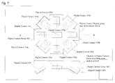
- Fig. 7 is a diagram which shows an example structure of a digital camera group 360 which forms the aerial image acquisition system 100 of the present invention.
- Eight oblique direction digital cameras from 350b to 350i are arranged to form the digital camera group 360 on the periphery of a digital camera 350a in a directly down direction so that a horizontal disc direction is divided radially into equal intervals and so that an optical axis is an angle which forms a gravity direction with the aim of efficiently photographing the ground surface from various view points.
- any support structure other than the digital cameras 350a ⁇ i which form the digital camera group 360 can be used as long as it is light and rigid such as a honeycomb structure aluminum plate or carbon resin.
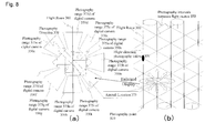
- Fig. 8 shows an example setting of a flight path and photographic points of an aerial image acquisition system by an aircraft.
- Fig. 8 (b) shows an example setting of photographic points 310. Flight is made with u-turns and returnings as shown in Fig. 8 (b) with a dotted line at equal intervals in order to form a mesh of photographic point 310. During this time, photographs are taken at photographic points 310. The mutual intervals between photographic points 310 are stipulated by a flight path photographic interval 372 and a flight path photographic interval 371.
- the flight path photographic interval 372 and the flight path photographic interval 371 are preferably set at about 80m or less in order to obtain at least one image within the range i 221 of the sufficiently small solid angle in Fig. 2 .
- the range shown by the photographic range 375a ⁇ i of the digital cameras 375a ⁇ i is photographed in the case of photographing using the digital camera group 360.
- the flight altitude is not limited to 800m. It is possible to set the flight altitude range from 200m or more to 2500m or less. When the flight altitude is lower than 200m, the amount of photographed images and the amount of processing increase significantly. In addition, when the flight altitude is higher than 2500m, it becomes difficult to obtain detailed images of the ground surface.
- the direction of the digital camera 350a which photographs in a directly down direction with respect to the flight path 300 is drawn with a horizontal direction of an image frame in Fig. 8(a) to a forward direction of the flight path 300.
- the direction is not limited to this, and the direction of the digital camera 350a which photographs in a directly down direction with respect to the flight path 300 may be set with a vertical direction of an image frame in Fig. 8(a) to a forward direction of the flight path 300.
- Fig. 9 is a diagram which shows an example of structure of an aerial image acquisition system.
- the aerial image acquisition system is comprised with a flight navigation system section 385 and a data acquisition registration system section 390.
- the flight navigation system section 385 is a device for navigating the aircraft 301 to a photographic points 310 stipulated in Fig. 8(b) , which is located along the flight path 300, aircraft location data is cyclically obtained by GPS 380, and avionic data 387 such as orientation, altitude and speed of the aircraft is obtained by an aircraft instrument 388. Because these signal interfaces are standardized as aircraft bus signals, there is not novelty. It is possible to calculate data related to the orientation of each digital camera from the orientation of the aircraft, relative location and pointing direction of each digital camera with respect to the aircraft.
- a function of the flight navigation system section 385 is to guide the pilot by a display screen example of the flight navigation system section of the aerial image acquisition system shown in Fig. 12 by a process of the flight navigation system section of the aerial image acquisition system in Fig. 10 according to an aerial image acquisition planning file 101 in Fig. 11 .
- the flight navigation system itself may not have novelty, the part for efficiently guiding an aircraft to photographic points 310 in order to achieve the goal of the present invention is a part related to the present invention.
- aerial images of which part of a city which are to be acquired is determined before flying.
- the photographic range is determined on a map, and a flight plan is decided.
- the flight plan is performed by setting flight route 300 on an aerial map.
- Photographic points 310 may be set at altitude range of 200m or more to 2500m or less or more preferably, 500m or more to 2000m or less from the ground in a mesh shape in order to achieve the goal of the present invention.
- the flight route 300 is set to be parallel based on the result of this setting.
- the flight path No. shown in the aerial image acquisition planning system 101 in Fig. 11 is allocated to each straight line section, photographic points 310 are allocated to each flight path so as to form an entire mesh, and the starting and finishing coordinates of each flight path and the number of photographic points and the coordinates of each photographic point are set by latitude, longitude and altitude. In this way, the aerial image acquisition planning system 101 in Fig. 11 is constructed.
- a graphic user interface related to the construction of the aerial image acquisition planning system 101 can be realized as a map data system.
- a function of the flight navigation system section 385 is shown by a process flow of the flight navigation system section of the aerial image acquisition system described in Fig. 10 .
- a planned flight path No. is displayed in order as in Fig. 12 until all photography is completed from the flight path registered in the aerial image acquisition planning file 101 by process block 420. Since the specified flight path No. includes a starting coordinate, the location, altitude, forward direction and speed of the flight path starting point are specified in order to start this flight path No. by process block 421 and the contents of Fig.12 are displayed on a monitor and guidance begins.
- process block 421 In order to perform photography, it is desirable that conditions stipulated by process block 421 satisfy a fixed error range, for example, a location error with an accuracy from 10m to 30m or less, or a flight direction error with an accuracy of 5 degrees of less. In the case where such conditions are not satisfied, the flight path may be performed again. When performing a flight path again, the guidance of block of 421 is performed again by block 423. In the case where the conditions of block 422 are satisfied, each photographic point from the photographic point coordinates described in the serial image acquisition planning file of the flight path No. selected by the process block 420 to the final photographic point coordinates, are guided in order by the process block 424 and the process block 425.
- a display screen example of the flight navigation system of the aerial image acquisition system is shown in Fig. 12 .
- the photographic guidance display 437 and location deviation display 446 shown in Fig. 12 are used in order to guide the aircraft 301 to the starting point of a flight path No. specified by the block 420. It is possible to know a deviation from the flight route 300 of the aircraft location 373, and any deviation is removed by operating the aircraft.
- Data related to the location of an aircraft is obtained by GPS 380 and altitude, forward direction, speed and pitch yaw roll as orientation data are obtained from flight instrument 388 as avionic data 387 and used in the display of Fig. 12 .
- a flight path during flight is displayed by a flight path No. display 439, and the number of photographic points to be photographed is displayed on the photographic guidance display 437. Since a photographic point No.
- a pilot operates the aircraft so as to pass through the photographic allowable range 440 with respect to each photographic point.
- the aircraft location display 373 is normally displayed on the lower left side of the screen.
- Fig. 9 an aircraft floor hole 397 for aerial camera devices is arranged on the lower side of the aircraft 301. It is preferred that the digital camera group 360 is set in this hole so that it does not stick out from the aircraft.
- a structure which hangs down to the aircraft floor hole 397 is adopted using a stability platform device 395 which is described later. In this way, a stability platform control system 394 and the stability platform device 395 are oriented and the direction of the digital camera group 360 which is directly below towards the ground is fixed in a stipulated direction regardless of the orientation of the aircraft 301.
- the stability platform device 395 can be omitted if the pitch roll of the aircraft is normally maintained by operating within 5 degrees.
- an inertial measurement unit IMU 396 on the stability platform device 395 it is possible to measure the orientation of the digital camera group 360.
- the upper surface of the digital camera group 360 may stick above the aircraft floor 398.
- An IMU 400 which observes the orientation of the aircraft 301, an aerial photograph control system 393 which includes a program for controlling and the digital camera 350 and for photograph data processing, a primary aerial image file 102 formed by a memory device such as a large capacity disk which records various data including image data, and aerial image acquisition planning file 101 which records photography points for outputting photography commands to the digital cameras are installed in the data acquisition registration system section 390 within the aircraft.
- An antenna of the GPS 380 for measuring the location of the aircraft 301 is included in a place for allowing the outside of the aircraft to be viewed.
- Fig. 13 shows the flow of data between devices in the data acquisition registration system section 390 in Fig. 9 .
- Fig. 14 explains a process flow of the photography control system 393.
- the photography control system 393 is formed with use of a CPU.
- the photography control system 393 periodically imports orientation data of the stability platform device 395 from the IMU 396.
- the IMU 400 which is fixed to the aircraft 301 periodically imports orientation data of the aircraft 451 to the photography control system 393 and the GPS 380 periodically imports GPS antenna location data to the photography control system 393.
- the processes of the photography control system 393 are explained in detail in Fig.
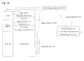
- the obtained location data 452 of the GPS antenna and orientation data 451 of the aircraft are references in order by the process block 360 and block 461, a flight path No. is specified, a judgment is made whether the aircraft is passing through a near point of a photography point of the specified flight path by the process block 462 in order until the flight path is withdrawn or photography of this flight path No. is completed, and aircraft data section 472 within the aerial image one dimensional file shown in Fig. 15 is imported by the block 472 at the same time as when a photography command 457 is sent at the same time by the block 463 to each digital camera 350 which form he digital camera group at the nearest timing to a photographic point within the photography allowable range 440.
- One digital camera 350 can hold 32GB of internal memory at the time of the present invention. As a result, it is possible to store photographed image data 455 at least until one flight No. is completed.
- the aircraft 301 performs a u-turn while one flight path No. finishes and the next flight path No. begins, and because photography is not performed during this time, image data 455 within the digital camera 350 is either sent by the process block 465 to the primary aerial image file 102 formed by a memory device such as a large capacity disk device installed in an aircraft, or image data stored within the digital camera 350 is deleted by exchanging the memory.
- a camera ID of a header part is a number for identifying each digital camera 350a ⁇ i, which form the digital camera group 360.
- the image data ID is an identification number so that images can be mutually identified, photography data and time corresponds to the aircraft data section 472, and are used for assessing the optical axis direction of each digital camera 350a ⁇ i in the aerial image database generation registration process 120.
- the image data part 471 does not perform any particular process at this stage. In addition, because camera parameters of the image header part 470 are fixed during flight, the same setting values are written.
- the aerial image database generation registration system 120 is explained in detail with reference to Fig. 16 to Fig. 26 .
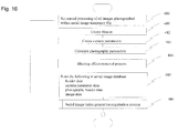
- Fig. 16 describes an entire process flow.
- all the images are processed in order in the primary aerial image files 102 which are accumulated during one day's flight by the aerial image acquisition system 100 after the flight is completed.
- a header of the image header part 490 of the aerial image database is created by the process block 481.
- a process for calculating photography parameters of the image header part 490 for each image in the process block 483 is explained in detail below. It is possible to stipulate the camera location by latitude, longitude and altitude. In the case where location measurement by a usual aircraft installed GPS 380 is by a DGPS, flight altitude is sometimes low and thus a precise location can not always be obtained as it is. Because an error is sometimes included on the case where location measurement by GPS 380 is a GPS, it is possible to obtain coordinate correction data from a nearby DGPS station which are measured at the same time as the flight time after landing and make a correction according to the photography date and time.
- Three dimensional or two dimensional points can also be expressed by vectors towards the origin.
- a matrix is described in bold capital roman characters, and in the case where classification is required in the present text, "(matrix)" is added before the characters.
- Greek symbols are used for angles, and symbols for planes, lines etc are placed with description of planes, lines etc before them.
- Unit vectors in a Cartesian coordinate system which indicates a north facing horizontal direction are described by (vector) N and used as a reference axis. Coordinate conversion via pitch yaw roll of an aircraft are denoted by (matrix) A with (vector) N being the reference.
- the location of the aerial data part 472 in the primary aerial image file 102 is denoted by X in the Cartesian coordinate system
- a location disparity from the GPS antenna within the aircraft to the digital camera group 360 is denoted by (vector) D in a vector notation.
- Normalized vectors to directions of 4 corners of an image, which is adjusted with an orientation conversion (matrix) A with respect to a reference direction of the aircraft are AGk1, AGk2, AGk3, AGk4 using (matrix) A and (vector) Gk1 to Gk4 for each camera respectively.
- terrain data of the ground surface is expressed by latitude, longitude and altitude with respect to a grid point of the ground surface, a triangle is formed by the immediately adjacent 3 sets of points and its apex coordinate is given as T1, T2, T3 with Tc being the intersection coordinates of a plane of triangle T1T2T3 and (vector) Gkc.
- Tc is within the triangle T1 T2T3. That is, they intersect.
- a, b are arbitrary scalar constants.
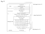
- R is an image distance of the photography parameters in Fig. 17 .
- Image distance means the distance from a photography location up to where the photography optical axis intersects terrain 580.
- each of terrain upper nearest right coordinate (latitude, longitude, altitude), terrain upper furthest right coordinate (latitude, longitude, altitude), terrain upper furthest left coordinate (latitude, longitude, altitude), terrain upper nearest left coordinate (latitude, longitude, altitude) are calculated.
- a frame rotation angle of the photograph parameters shown in Fig. 17 is calculated.
- a frame rotation angle is cos - 1 ⁇ A ⁇ 1 2 ⁇ G k ⁇ 1 + G k ⁇ 2 - G kc • 1 2 ⁇ G k ⁇ 1 + G k ⁇ 2 - G kc ⁇ 1 2 ⁇ G k ⁇ 1 + G k ⁇ 2 - G kc ⁇ ⁇ A ⁇ 1 2 ( G k ⁇ 1 + G k ⁇ 2 - G kc ⁇
- ".” expresses an inner product and the part enclosed by 2 lines in a vertical direction expresses a norm.
- a process for removing the effects of blurring is performed by the process block 484.
- the aerial three dimensional video generation system 150 related to one embodiment of the present invention visual data from various directions of a city landscape is expressed using original images photographed from different view points.
- the photography data and time will become different for each original image and therefore it will be difficult to watch when integrating video.
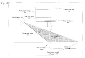
- Fig. 18 shows the relationship between an image and vision in the removal process of blurring effects.
- the bottom end of photograph image 495 is the nearest part of the photography ground surface part 499 of the closeup part a496.
- the upper end part of photograph image 495 is the distant view part 498 and is located at the furthest part of the photography ground surface part 499.
- a histogram of brightness of an image pixel in the case of no fine water droplets (blurring) is a normalized histogram 500 distributed from a luminosity lowest value to a luminosity highest value
- a histogram 501 with respect to the closeup part is obtained, the width between the highest value and lowest value becomes more narrow, and a center value becomes whiter, that is, shifts in a high luminosity direction.
- a range of the histogram in the image horizontal direction is the total range and the vertical direction is a strip having a fixed width as in the closeup part a496, closeup part b497, and when a histogram of pixel luminosity is calculated heading upwards while shifting one line at a time, the characteristics shown in Fig. 19 are obtained.
- a value range fitting curve 513 has a monotone decrease and a center value fitting curve 512 has a monotone increase which is similar.
- each pixel value is corrected by a value range calculated from a fitting curve and a center value correction function for each row. Correction of luminosity of each pixel is calculated with: Center value of the normalized histogram + brightness of pixel - center value fitting value * width of the normalized histogram / width of fitting value for each horizontal line.
- Fig. 21 shows a process result example of the removal process of blurring effects of the present invention and as a result of processing the blurring effect removal before image 530 the blurring effect removal after image 531 is obtained.
- process block 485 is stored in the image data part of the aerial image database 143 shown in Fig. 17 .
- An index is produced with aim of rapidly searching the aerial image data in order to generate video using aerial image data registered by process block 485 by the last process block 486 of the process flow in the aerial image database registration system in Fig. 16 .
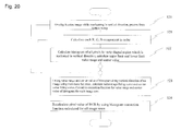
- the contents of process block 486 are further explained in detail by the aerial image index generation registration process flow of the aerial image database registration system in Fig. 22 . Below, this is explained according to Fig. 22 .
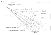
- the contents of process block 540 are explained while referring to the structure of the aerial image index mechanism and term definitions in Fig. 23 .
- Photography location (latitude, longitude, altitude) 550, normalized image vector G t (X Y Z) 551, frame rotation angle 553, image distance 552, terrain upper center point coordinate (latitude, longitude, altitude) 554, terrain upper nearest right coordinate (latitude, longitude, altitude) 555, terrain upper furthest right coordinate (latitude, longitude, altitude) 556, terrain upper furthest left coordinate (latitude, longitude, altitude) 557, terrain upper nearest left coordinate (latitude, longitude, altitude) 558 are already stored as photography parameters of the aerial image database 133 in Fig. 17 in an image photographed by the photography device 550, and this is shown in Fig. 23 . An image photographed by the photography device 550 captures a ground surface image range 549.
- longitude latitude are defined for the ground surface, terrain 580, it is possible to form a cell with a latitude direction of 30m and longitude direction of 25m in the vicinity of latitude 35 degrees of the Tokyo area when meshing every second. Considering a city region of square of 65km lengths, the number of these cells is merely 35M cells. Because 4 corner points of the ground surface image range 549 are judged by latitude longitude it is easy to calculate the ground surface cell 559 included in the ground surface image range 549
- apex vector 570 which points upwards in a vertical direction from the center of the ground surface cell 559 is defined, the sphere is cross sectioned in concentric circles with this apex vector as a reference and apex index i572 is defined.
- a solid angle cell center vector is defined from the ground cell 559 passing through the apex index 572.
- the solid angle cell center vector 574 is always defined by a fixed direction angle interval on the apex index 572.
- the solid angle cell 573 in Fig. 24(a) corresponds to the range
- Fig. 24(b) is a circular cone having an apex angle of 20 degrees which forms the solid angle cell 573 with respect to the solid angle cell center vector 574, and is defined as a circular cone in which a vector which is a solid angle with a steradian of 0.4 fits.
- Fig. 24 is a diagram of the ground surface cell 559 seen from an apex direction.
- the solid angle cell 573 is defined by mutually overlapping with and being adjacent to the apex index i572, and fills up the entire circumference of the apex index i572.
- An angle which forms the solid angle cell center vector 574 which passes through the apex vector 570 and apex index i570 is called apex elongation 571 and becomes a numeric value for defining the apex index
- Fig. 25 shows an index structure of the solid angle cell 573.
- Fig. 25(b) is a diagram looking down on the ground surface center pointer 575 from the apex direction. Defining a solid angle cell address (i, j) having a two dimensional subscript, i indicates the apex index i 572 and j indicates a solid angle cell in the direction of the j th concentric circle of the apex index i.
- a solid angle cell center vector of the solid angle cell address (0,0) 584 is the apex vector 570 and surrounding this, solid angle cell address (1,0) 585, solid angle cell address (1,1) 586, and cell solid angle address (1,2) 587 on a sphere in concentric circles are defined below up to filling the circumference of the apex index 1.
- Solid angle cell address (2,0) 588, solid angle cell address (2,1) 589, and solid angle address (2,2) 590 are defined up to filling the entire circumference of the apex index 2 along the apex index 2 on the exterior side of the apex index 1 581.
- the solid angle cell 573 mutually overlaps and the sphere is completely filled so that there are no gaps.
- a solid angle of a solid angle cell is set so that three dimensional video generation is smoothly performed.
- the number of solid angle cell addresses becomes larger as the apex index gets close to the ground. In this way, it is possible to search for an image of a photographed ground cell with respect to all ground cells by the direction on the sphere.
- FIG. 26 A structure of a related table of an aerial image index and mutual relationship are shown in Fig. 26 .
- the structure of an apex index and apex cell address is the same and don't rely on a ground cell, are this structure is defined by apex index parameter table ZNPRMT597 and direction index parameter table DRPRMT598.
- the apex index parameter table ZNPRMT597 defines an apex elongation 571 with respect to apex index i 572 in order from an apex index 0, and a center vector 574 corresponding to the apex index i572 houses the vertical direction component in the case where it is a normalized vector as a vertical direction component.
- the direction index parameter table DRPRMT598 stipulates the direction X component and direction Y component of the solid angle cell center vector for each solid angle cell address corresponding to the direction number NDRi defined corresponding to an apex index, and is normalized so together with the vertical direction component described in apex index parameter table ZNPRMT597 so that a vector norm becomes 1.
- a ground cell location index table TCINXT600 in Fig. 26 is defined with respect to all the ground cells 559, and index table address ADDR ij 603 is specified corresponding to a ground cell.
- a subscript of ADDR ij indicates that a longitude index LONINX601 is i, and a latitude index LATINX602 is j corresponding to a location on the ground.
- Apex index table address ADDR ij (603) indicates an apex index table ZNINXT604 corresponding to ground cell ij.
- Direction index table address ADDR ijk (605) corresponding to a selected apex index k is defined in the apex index table ZNINXT, and the direction index table DRINXT606 is stipulated according to this. Because there is the number of direction specified by the apex index parameter table ZNPRMT597 here, if the direction index is m, then ADDR ijkm , is specified as the address of image address table 608.
- An image address table selected in this way shows the number of image data included in a solid angle cell of a solid angle cell address (k, m) with respect to ground cell ij, and an image data address. In this way, when an aerial image index and mutual relationship of a related table are defined according to Fig. 26 , it is possible to search an image photographed from an arbitrary direction from a ground location.
- a flow of an aerial image index generation registration process of the aerial image database registration system shown in Fig. 22 is explained below based on the explanation of the structure of the image data index above.
- All the ground cells included in a ground image range 549 are calculated when there is one image as shown in Fig. 23 in the process block 540.
- processes are performed in order on all the ground cells calculated in process block 540.
- a vector which calculates a photography location 550 from a ground cell center coordinate is calculated.
- a solid angle cell address (k, m) which includes the vector which calculates the photography location 550 from a ground cell center coordinate is calculated using an inner product calculation from the definitions of apex index parameter table ZNPRMT597 and direction index parameter table DRPRMT598.
- Image data of the image data table ADDR ijkm is increased by one by the process block 545 based on this data and added to the image database.
- FIG. 27 An example structure of vision by digital cameras having three different focal lengths is shown in Fig. 27 .
- city landscape three dimensional video generation of the present invention because an original image which has few depression angles becomes an image with a large off-nadir angle, it inevitably becomes an image further away than an aircraft. This is because in order to generate a video image with few depression angles without reducing resolution care is necessary in order not to deteriorate resolution when photographing images with a large off-nadir angle.
- Fig. 27 An example structure of vision by digital cameras having three different focal lengths.
- FIG. 27 shows an example whereby the focal length of a telescopic lens is increased as the off-nadir angle becomes larger, and at the same time as maintaining resolution, digital cameras having three types of off-nadir angle are adopted, focal length is increased as the off-nadir angle increases and ground resolution becomes uniform.
- a directly below photography digital camera 350a in Fig. 28 up to 8 digital cameras 350b ⁇ i are radially arranged with the same small off-nadir angle and on the exterior side up to 16 digital cameras 620 j ⁇ y are radially arranged with the same large off-nadir angle. It is possible to sufficiently store already existing aerial photography cameras in an aircraft floor hole due to small size and high capabilities of recent digital cameras.
- FIG. 29 A photography range example of the digital camera group formed by digital cameras having three different types of focal length is shown in Fig. 29 .
- FIG. 30 A simplest example of the structure of a stability platform device 395 for installing in an aircraft is shown in Fig. 30 .
- the stability platform device 395 sits astride the aircraft floor hole, and is formed by fixing part 635, up and down moving part 636 and rotation part 637 from the bottom which are arranged so be closed off by the upper part.
- the rotation part 637 has a rotation table structure, an orientation detection IMU 396 is fixed to the top of it, the digital camera group 360 hangs down from the bottom part and the entire downwards field of view can be seen by the digital cameras 350a ⁇ i without projecting the cameras from the aircraft floor hole 397.
- the stability platform device 395 hangs down the digital camera group 360 or 621 and it is possible to similarly photograph using digital cameras 350a ⁇ i or digital cameras 620j ⁇ y. Furthermore, a joining method of the rotation part and digital camera group 360 or 621 needs to be fixed and provide rigidity.
- the stability platform device 395 aims to keep a fixed position with respect to disturbance of the aircraft's orientation, however, it is safe to assume a pitch and roll angle from 7 to 10 degrees at most and a yaw angle of 20 degrees at most of orientation disturbance of an aircraft.
- the fixing part 635 is fixed to the aircraft floor 398.
- the up down moving part is held via up down drive mechanisms A ⁇ D641 ⁇ 644.
- the up down drive mechanisms A ⁇ D641 ⁇ 644 each move up and down independently and correct for disturbance of a pitch and roll angle.
- the up down drive may be a hydraulic mechanism and may have a method for converting to rotation movement to up down movement via a worm gear.
- the rotation part 637 is installed to the up down movement part 645 by being held by a bearing mechanism.
- the rotation drive mechanism 640 is fixed to the up down movement part 636 and the rotation part 637 is arranged by being connected to an exterior extension part. Rotational movement may be transmitted between the rotation part 637 and the rotation drive mechanism 640, and disturbance with respect to a roll angle of the aircraft is removed by rotating the rotation part 637.
- a signal data flow of the stability platform device is shown in Fig. 31 .
- a stability platform control system 394 periodically inputs a pitch angle, yaw angle and roll angle by the IMU396, a disparity from a reference value is calculated, the up down drive mechanisms A ⁇ D641 ⁇ 644 are controlled in order to remove disparity in a pitch angle and roll angle, and up down movement 649 is carried out.
- Rotation mechanism 640 is controlled and rotation movement 650 is carried out in order to remove disparity of a yaw angle.
- FIG. 32 view points move together with time t along a viewpoint route P(t) 270, and during this time, the ground surface is taken from a location on the view point route P(t) 270 along a target trajectory T(t) 280 by the sight line vector V(t1) to V(t4), V(t) from time t1 up to time t4, ti.
- an aerial image m-1 666 which has little disparity close to the sight line of view point P (t1) 675, view point P (t2) 676, is search using the aerial image database 130, between the sight line vectors V (t1) 681, V (t2) 682, V (t3) 683 of times t1, t2, t3, a difference in disparity with the image vector G m-1 672 is corrected by a morphing process on aerial image m-1 666, connected and smooth video images are generated.
- a disparity due a difference in view points is smaller for the aerial image m than the aerial image m - 1 666 from the sight line vector V (t4) at time t4, the aerial image m 667 is switched to the original image, and a city landscape three dimensional video is generated by correcting a disparity with the aerial image m 667 by a morphing process on the aerial image m 667 until the next original image following the sight line vector V (t4) at the time t4 is selected.
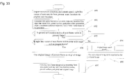
- Fig. 33 shows the above processes by a process flow, and movement direction, movement speed, location and sight line direction vector which should be calculated as the next video frame (next frame) are imported by graphic user interface 180 in process block 690.
- process block 691 the view point location, sight line vector, desired point coordinates on the ground of the next frame are calculated based on this value.
- the process block 692 judges whether the ground index location of the next frame is the same as the present frame using the center points of the present frame and the next frame. In the case where they are not the same, it is necessary to search again the most suitable original image and move to process block 694. In the case where they are the same, in the process block 693 it is judged whether the sight line vector of the next frame is within the same solid angle cell of the present frame.
- process block 700 the ground cell address (i, j) at the center of the next frame is calculated and a sight level vector which connects the center point and the view point of the next frame is created and normalized. From the process block 701 to 703, solid angle cell address (k, m) is calculated from this normalized sight line vector by referring to the apex index parameter table ZNPMRT597 and the direction index parameter table DRPRMT598, and the address ADDR ijkm of the image address table is calculated together with the ground cell address (i, i).
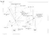
- process block 705 judges whether all of four end points Ti1 715, Ti2 716, Ti3 717, Ti4 718 on the ground surface at an sight line of view point P (ti) are photographed in images from original image photography location S A 710, original image photography location S B 711, original image photography location S C 712, and this can easily be done by a vector outer product calculation.
- Z mH Z mH .
- Z mH Z m ⁇ 34 ⁇ Z m ⁇ 12 ⁇
- a surface which passes through Z mc and is defined by (vector) Z mV and (vector) Z mH is called a terrain plane (plane) and is expressed as Z m .
- a plane perpendicular to G m which passes through Z mc is called (plane) N m .
- (plane) N m is a photographed image (vision) from an original image photograph location view point S m .
- a conversion (plane) Z m --> (plane) N m exists and this is called ⁇ A .
- a plane perpendicular to sight line vector Vi which passes through T iC is called Ni.
- Plane T mi forms one part of Z m at sight line by the view point Pi within terrain surface Z m . If view point P i and (vector) Vi and vision angle ⁇ i are decided then vision (plane) Ni of view point Pi and (plane) Tmi are uniquely decided.
- n m • Z mV 0
- n m • Z mH 0
- an inner product is expressed as ".”
- a normalized sight line vector of 4 corners of vision of view point Pi is given as Vi1, Vi2, Vi3, Vi4, and it is possible to calculate the coordinates of these and a the intersection point Ti1 of terrain plane Zm, T i2, Ti3, terrain plane Zm of Ti4.
- the rotation around z axis is given as: V Ax V Ax 2 + V Ay 2 V Ay V Ax 2 + V Ay 2 0 - V Ay V Ax 2 + V Ay 2 V Ax V Ax 2 + V Ay 2 0 0 0 1
- the rotation around y axis is given as: V Az 0 - V Ax 2 + V Ay 2 0 1 0 V Ax 2 + V A ⁇ y 2 0 V Az
- V Ax V A ⁇ x 2 + V A ⁇ y 2 V Ay V A ⁇ x 2 + V A ⁇ y 2 0 - V Ay V Ax 2 + V Ay 2 V Ax V Ax 2 + V Ay 2 0 0 0 1 ⁇ V Az 0 - V Ax 2 + V Ay 2 0 1 0 V Ax 2 + V Ay 2 0 V Az V Ax V Az V Ax 2 + V Ay 2 V Ax V Az
- a three dimensional video is generated as seen from a human eye from an arbitrary place on a road or passageway, and from an arbitrary sight line direction with respect to an arbitrary city place.
- three dimensional videos are generated related to structure in a city space the same as aerial three dimensional video generation or three dimensional video is generated using an actual image without generating a three dimensional model.
- the level of freedom is less on a road and while existing places are limited to 1.7m above ground on passageways, because passageways have a different structure to terrain models by DEM, passageways can be modeled by graph expression.
- a projection plane of an actual image photographed in advance must be set.
- an original image photographed on a road of a vertical plane along a boundary line of an urban area other than a passageway is mainly converted to a projection plane, and a vertical surface which is separated a fixed distance and which intersects a road with respect to a forward direction view or rear direction view is supplementarily converted to a projection plane.
- a digital camera group which photographs in 8 or 16 directions of the entire circumference in a horizontal direction, and across 8 or 16 directions of the entire circumference in an oblique direction which is an angle of elevation from horizontal, is arranged on the roof of a vehicle, and a road image database is constructed. Furthermore, the oblique direction may be omitted by using a wide angle lens.
- Video image generation is formed by a process for selecting the most suitable original image, and by a process for generating a smooth video image by morphing using a movement state of a view point, sight level direction and location within a city.
- Fig. 40 describes a process flow of a road image acquisition system, and a detailed realization method of this road image acquisition system 110 is explained up to Fig. 59 .
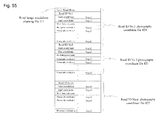
- the photography point setting process 741 in order to be able to photograph at fixed distance intervals along roads and passageways within a city, movement route and photography points or intervals are set and the road image acquisition planning file 111 shown by the structure in Fig. 55 is made.
- this photography plan a road ID No. and photography points on a road are defined.
- a photographed image within a digital camera is accumulated in the primary road image file 112 together with a location and orientation data acquired in the photography process for each timing determined in advance.
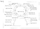
- Fig. 41 is a diagram which shows an example structure of a digital camera group 755, which forms the road image acquisition system 110 of the present invention.
- Horizontal direction digital cameras 750a ⁇ h are arranged radially so that the entire circumference is split into equal intervals with the aim of densely and efficiently performing photography from various view points on a road, and digital cameras 750i ⁇ p are arranged with the aim of photographing in an oblique direction of the digital cameras 750a ⁇ h, forming a digital camera group.
- any structure can be used as long as it is light weight and provides a high level of rigidity, and can be formed by a honeycomb structure aluminum plate or carbon resin.
- Fig. 42 shows an example of setting of a route and photographic points of the road image acquisition system by a vehicle.
- Fig. 42 (b) shows an example of setting of photographic points 766.
- the road image acquisition system 765 performs photography at photography points 766 while moving along a road according to photography points 766 formed finely in a row shape on a road by the road image acquisition planning file 111.
- the mutual intervals between photographic points 766 are selected by three dimensional video generation system morphing so that a photographed image becomes a smooth video.
- the photography range shown by the photography range 760a ⁇ p of the digital cameras 750a ⁇ p in Fig. 42(a) is photographed.
- each digital camera of the photography range 760a ⁇ p of the digital cameras 750a ⁇ p and level of mutual overlapping changes according to the setting of a focal length of a lens. From the goal of the present invention, it is preferred that the cameras are set so that the ground surface is almost consecutively covered while slightly overlapping each other.
- Fig. 43 shows the relationship between a vertical direction photography pattern and image projection plane of the road image acquisition system. While a projection plane of the image photographed in aerial three dimensional video generation is a terrain, in the road three dimensional video generation a human eye is the realization object and therefore terrain can not be used for a projection plane.
- a projection plane of an image photographed from the road is a surface which stands perpendicular to a boundary line between roads and buildings as is shown in Fig. 43 .
- a boundary line between roads and buildings may approximately also be a boundary surface of a road.
- the definition of an image projection plane is the definition of a road and must be strictly defined and turned into a database, and this is explained later.
- a road can be anywhere regardless of the transport capabilities of a vehicle as long as it is a road at human sight line and a below ground level road or a road within a building can be used as long as there is a passageway for people.
- Fig. 43 an example is shown of a photography range and direction of the digital cameras 750i ⁇ p and a photography range and direction of the digital cameras 750a ⁇ h.
- a boundary surface of a road or passageway is turned into a projection plane of an image and due to this relationship the original image of a video image must be able to be searched from any place on a road and also registered. High speed is required for searching, and the image must be able to be searched from various directions at human sight line and registered.
- a road database system which achieves this goal is explained in Fig. 44 to Fig. 52 . The descriptions here form the technical basis of the road three dimensional video generation system.
- Fig. 44 shows a description method of a road using a graph.
- a road has a width and forming a graph using the center line of roads is the basis of a road expression.
- a center line of a road is called a center line graph 780. It is formed by an end point and side. An end point always exists at an intersection point, a confluence point, a branch point and a veer point of a road.
- a road has two end points and is always defined as a group of consecutive sides and end points, and a road ID No. 777 is uniquely provided.
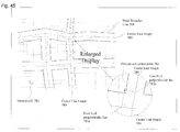
- Fig. 45 shows a method of searching for a road using latitude and longitude.
- a mesh When a mesh is created at a latitude and longitude of 0.1 second units for example, this becomes a mesh with a latitude direction of 2.5m and a longitude of 3m in the Tokyo area.
- a mesh When a mesh is created in this way, a road either always exists or does not exists in each mesh.
- This mesh is called a ground cell 781. It is possible to access a road if a road exists from an arbitrary geographical point reveled by latitude and longitude by allocating a road ID No. to the ground cell 781 when a road exists.
- one mesh has a relationship with a plurality of road ID Nos. Drawing a perpendicular line to a center line graph from a ground cell center point 782, an ID No.
- a road ID No. of a ground cell is defined as the road ID No. of a ground cell.
- a road ID No. of the perpendicular line foot B783b is selected which has a shorter perpendicular line compared to the perpendicular line foot A783a.
- Fig. 46 stipulates a structure of a road database for describing the structure of a road.
- the ground cell index table CLLRDINXT can search a relative record address for showing the graph part of a road graph data table which includes a road ID No. and a road graph table corresponding to the road ID No. from an index (i, j) of a meshed latitude longitude.
- a road graph address table RDGRADRT specifies a start address within the road graph data table RDGDT corresponding to a road ID No. This is because the size of an end point and side of the road graph data table RDGDT are different depending on the road ID NO.
- the road graph data table RDGDT describes the structure of a road as a graph.
- a first record is the road ID No.
- the second record is the number of total end points. It is repeated until the range of a road specified by a road ID No. is used up which describes the attributes of an end point and side up to an end point sequentially from a starting point. Attributes have the following three types.
- Road ID No. k 777k and road ID No. I (L) 7771 intersect at end points, ki+2 79k, i+2 and end point i, j+2 793i, j+2 which are at the center of an intersection point.
- 2 subscripts are used to express an end point, the first subscript expressing a road ID No., the second subscript showing the order of an end point within the same road ID No. Furthermore, this end point separately names the same end point on both roads.
- end point k, i+4 792k, i+4 the structure description of the road ID No.
- Fig. 48 shows a method of describing a junction of three roads.
- Fig. 49 shows a method of describing a branch road.
- I (L) 777l is based on the road graph data table RDGDTI (L) 795l in Fig. 49 - 2 and Fig. 49 .
- Fig. 50 shows a method of describing a veering road.
- Fig. 51 shows a method of describing a non-orthogonal intersection point.
- Fig. 52 shows a method of describing a congruence road.
- the process continues after end point l, j+6 793l, j+6.
- Fig. 53 shows an example of a structure of the road image acquisition system 110, which is formed by a car navigation system section 801 and a data acquisition registration section 800.
- the car navigation system section 801 is a device for guiding a vehicle 803 along a movement route 765 to photography points 766 stipulated in Fig. 42(b) , and vehicle location data is periodically obtained by GPS380.
- the function of car navigation system section 801 is to guide a vehicle using the display screen example of the car navigation system section of the road image acquisition system in Fig. 56 according to the content of the road image acquisition planning file 111 in Fig. 55 .
- the car navigation system itself is already publicly known and so it is possible to use a device which does not have novelty.
- the function of the car navigation system section 801 is shown by a process flow of the car navigation system section of the road image acquisition system described in Fig. 54 .
- the display in Fig. 56 is performed in order until all the photography is completed for planned photography roads from among the road ID No. registered in the road acquisition planning file. Because a start coordinate is included in a specified road ID No., in process block 811, the location of a travel start point, forward direction, speed are specified in order to start this road ID No., the contents of Fig. 56 are displayed on a monitor and guidance is performed.
- the travel route may be reset.
- Each photography point from a photograph point coordinate to a final photography point in a description of the road image acquisition planning file of a road ID No. selected in process block 810 are guided to in order by process block 812 and process block 813.
- IMU 400 which observes the orientation of vehicle 803
- road photography control system 806 which includes a program for controlling the digital camera 750 and processing photography data
- road image one dimensional file 112 which is formed by a memory device such as a large capacity disk device which records each type of data including image data
- the road image acquisition planning file 121 which records photography points for issuing photography commands to the digital camera 750 are included in the data acquisition system part 800.
- Fig. 57 shows the flow of data between structural instruments of the data acquisition registration system part 800 in Fig. 53 .
- Fig. 58 explains a process flow of a road photography control system 806.
- the road photography control system 806 is formed by a CPU.
- the road photography control system 806 periodically imports orientation data 450 of the stability platform device 395 from the IMU 396.
- orientation data 450 of the stability platform device 395 from the IMU 396.
- the IMU 400 which is fixed to the vehicle 803 periodically sends orientation data 928 of the vehicle, and the GPS 380 periodically sends location data 830 of the GPS antenna location to the road photography control system 806.
- a process of the road photography control system 808 is explained in detail in Fig. 58 .
- the contents of the road image acquisition planning file 111, the obtained location data 380 of the GPS antenna and the orientation data 828 of the vehicle are verified in order, a road ID No. is specified, it is judged whether a photography of this road ID No. is complete or a near point of the completion point of the road ID No. specified in process block 836 is being passed through in order up to a departing from a route, when a photography command 457 is sent to all the digital camera which form a digital camera group at the nearest timing to a photography point within a photography allowable range, a vehicle data section 840 within the primary road image acquisition file shown in Fig. 59 is simultaneously written by process block 838.
- Digital camera 750 can hold 32GB of internal memory at the time of the present invention. As a result, it is possible to store photographed image data 827 at least until one road ID No. is completed.
- the vehicle 803 completes one road ID No., and road image data 827 within the digital camera 750 is sent by the process block 839 to the primary road image file 112 formed by a memory device such as a large capacity disk device installed in the vehicle, image data stored within the digital camera 750 is deleted.
- An example of a structure of the primary road image file 112 is described in Fig. 59 .
- An image header part 470 and image data part 471 are prepared for each image.
- a camera ID of a header part is a number for identifying each digital camera 750a - i which form the digital camera group 755.
- the image data ID is an identification number so that images can be mutually identified, photography date and time corresponds to the vehicle data section 840, and are used for assessing the optical axis direction of each digital camera 750a - i in the road image database generation registration process 130.
- the image data part 471 does not perform any particular process at this stage.
- the same setting values are programmed.
- FIG. 60 A simplest example of a structure of a stability platform device 395 for installing in a vehicle is shown in Fig. 60 .
- the stability platform device 395 has the same structure as the stability platform device 395 for installing in an aircraft in Fig. 30 .
- the stability platform device 395 is fixed to a vehicle roof plate, and the digital camera group 755 for a vehicle is set on the stability platform device 395.
- the road image database generation registration system 130 and the road image database 150 are explained in detail using Fig. 61 to Fig. 69 . Due to a relationship of searching a road image database from an image projection plane, a sight line and a view point, firstly, the structural relationship between the structure of the image projection plane and road graph database 151 must be defined. Image projection plane is explained using the direction of a road graph and direction of a sight line vector in Fig. 65 . The road image, which is taken, of the entire circumference along a passageway on a road is projected onto a projection plane of a boundary line of the road, and a morphing process is performed depending on the relationship between a sight line and a view point. At this time, video in a forward direction or forward opposite direction, because a road is long and narrow, a very long road boundary surface is required in order to project an image which is sometimes difficult to realize.
- the front direction virtual projection plane 878 is used, the rear image photographed in the road image acquisition system 110 is used, and if an angle 882 formed by a road graph and a sight line is in a range from 160 degrees to 180 degrees of left and right, the rear direction virtual projection plane 879 is used, and the rear image photographed in the road image acquisition system 110 is used.
- a left projection plane 880 is used, and a left oblique front direction, left, left rear direction image with respect to the forward direction photographed by the road image acquisition system 10 is used, and if the angle 882 formed by a road graph and a sight line is in a range from right side 20 degrees to 160 degrees, then a right projection plane 881 is used, and a right oblique front direction, right, right rear direction image with respect to the forward direction photographed by the road image acquisition system 10 is used.
- an example of switching a projection plane where an angle 882 which is formed by a road graph and a sight line is front direction left right 20 degrees, rear direction left right 160 degrees is explained so far, however, it is also possible to vary the angle according to actual reality, increase the angle according to the realty of the actual place, and below the angle is set at 20 degrees as a concrete example.
- the road image database generation registration system 130, the road image database 150, and the road three dimensional video generation system 170 are constructed according to the method of the projection plane explained above.
- Fig. 66 the road three dimensional video generation system of the present invention searches for the most suitable original image and morphing is performed according to a disparity.
- an actual image with few disparities with respect to the provided view point and sight line must exist and must be able to be rapidly searched.
- an end point row is expressed as [end point m, i coordinate (X mi , y mi )] with respect to the n th end point from the front of a graph and a location on a section of a side which continues from this, however, this section is decided by the shape the road which is too long for the definition of a projection plane.
- a left right projection plane is defined as [projection plane section] corresponding to the left side and right side and its side with respect to a road graph direction as a projection plane section as is described in Fig. 66 , and divided into a graph formed by ends and sides.
- a left side projection plane section of a road graph direction 883 corresponding to an end point m, i coordinate (x mi , y mi ) 890
- a digital camera group 755 exists at an original image photography location R903, one digital camera 750 among these photographs an image of an image vector R904, which is a normalized vector, which expresses a camera optical axis, the image vector 904 and the image right side R906 intersect with projection plane section mir2 coordinate (x mir2 , y mir2 ) 897, and the image left side coordinate R905 intersects with projection plane section mir2 coordinate (x mir2 , y mir2 ) 897. Because the usage method of a projection plane in Fig. 65 is different due to an angle formed by the image vector and the road graph direction 883, an original image is linked with a projection plane and registered by the principle described below.
- an image vector R904 from an original image photography location R903 in Fig. 66 corresponds to (5) described above, the original image is linked to projection plane section mir2 coordinate (x mir2 , y mir2 ) 897 and registered.
- the image vector L900 from an original image photography location L899 in Fig. 66 corresponds to (2) described above, the original image is linked to projection plane section mil2 coordinate (x mil2 , y mil2 ) 893 and registered.
- the original image is linked to projection plane section mir1 coordinate (x mir1 , y mir1 ) 896, and projection plane section mil1 (x mil1 , y mil1 ) 892 and registered.
- the image vector B912 from an original image photography location B911 in Fig. 67 corresponds to (3) described above, the original image is linked to projection plane section coordinate mil2 (x mil2 , y mil2 ) 893, and projection plane section mir2 (x mir2 , y mir2 ) 907 and registered.
- FIG. 68 An image which is linked to a projection plane section 917 and registered is further sectioned depending on what type of sight line vector the projection plane section 917 is estimated with. That is, with respect to an image in which the projection plane section 917 enters, the vision is sectioned according to which sector from 931 to 937 is located on a line which links the original image location and the projection plane section center point 918.
- An original image photography location a 916a is sectioned into an angle 140-160 degree section 937 and an original image photography location c 916c is sectioned into an angle 80-120 degree section 934.
- An image vector d 919d which exists in a range of a forward direction left right 20 degrees of an angle formed by an image vector and a road graph direction 883 sections an original image into an angle 20-40 degree section 930 because a foot of a perpendicular line from the original image photography location d 916d exists in the projection plane section 917.
- An image vector e (919e) which exists in a range 921 of a rear direction left right 20 degree of an angle formed by an image vector and a road graph direction 883 sections an original image into an angle 160-180 degree section 938 because a foot of a perpendicular line from the original image photography location d 916d exists in the projection plane section 917.
- Fig. 68 The location relationship of a plurality of original images seen from human sight line location of an arbitrary plane which faces a passageway along the arbitrary passageway of the city is shown in Fig. 68 , and the projection plane section 917 is estimated and photographed by each image vector b (919b) and image vector c (919c) from an original image photography location b (916b) and an original image photography location c (916c).
- An angle (solid angle) which estimates the original image photography location b (916b) and an original image photography location c (916c) from an arbitrary point on the projection plane section 917 is at most 50 degree in Fig.
- an original image of a three dimensional visual data is prepared by an angle which estimates for each solid angle of an angle at most 50 degree (semi-apex angle 25 degrees) from an arbitrary point along the passageway.
- a solid angle is calculated using 2 ⁇ (1-cos ⁇ ) with respect to a semi-apex angle ⁇ in steradians, becoming 0.59 steradians and this is the upper limit of the solid angle.
- a projection plane and the image index method with respect to a road have been explained.
- the structure of a specific road image index mechanism is explained in Fig. 64 .
- the road graph database RDGDT 790 explained in Fig. 46 is extended so that a projection plane original image index table address 873 is added next after an attribute column, further sectioned into projection plane sections for a road original image projection for every end point and side which form the road graph database RDGDT 790m. That is, a relative record address of the road ID No.
- a projection plane section which belongs to the end point mi is divided into a left side (left wall) and right side (right wall) of the road graph direction 993 corresponding to the relative record address 874 in order from a start point.
- the number of cells is the number of projection plane sections that belong to the end point mi.
- An expression of a projection plane section is shown by its starting coordinate with respect to each projection plane section.
- a projection plane original image index table address 875 PJADRTADR exists in the projection plane original image index table PJINXT 871 with respect to each projection plane section of left right walls, and is linked to a projection plane original image index table PJADRT 872 corresponding to Fig. 68 .
- a road original image corresponding to a projection plane section is sectioned according to a sight line angle which estimates a projection plane section, the number of original images included in each section is described as road image data 869 and the original images are described as road image data address 870. In this way, a high speed search mechanism is completed.
- Projection plane section coordinate and sight line direction -> original image
- the road image database 153 must be formed by consistency between a road image index mechanism 152 and a road graph database 151 based on the data acquired in the primary road image file 112.
- the road image database 153 in Fig. 62 generates and registers according to the process follow of the road image database generation registration system in Fig. 61 .
- all images are processed in order in the road image one dimensional file 112 accumulated during one day's travel by the road image acquisition system 110 after photography is complete.
- a header of an image header part 850 in the road image database is created in Fig.
- a header of the image header part 470 of the primary road image file 112 in Fig. 59 is copied as it is.
- the camera parameters of the image header part 470 of the primary road image file 112 for the process block 845 may also be copied as it is.
- photography parameters of the image header part 850 are calculated for each image. This process is explained below.
- Camera location is stipulated by latitude, longitude and altitude, however, when location measurement via a general vehicle GPS380 is performed by a DGPS an accurate location may be obtained of the ground surface as it is. Because there are errors when location measurement via a general vehicle GPS380 is performed by a GPS, after travelling, coordinate correction data from a DGPS station which measures at the same time as when travelling may be obtained and correction performed according to the photography date and time.
- the case of the road image acquisition system 110 is different to the case of the aerial image because a road is travelled along only in two dimension and the distance between a photography point and the photography object is close compared to an image angle and therefore photography parameters may be calculated approximate to plane geometry.
- a camera location of a second record (road ID No.
- end point relative record address end point coordinate (x,y), end point distance, center line left right distance
- CLLRDINXT785 ground cell road index table CLLRDINXT785 in Fig. 46 if a road ID No. is not identified, a road graph address table RDGRADRT788 and a road graph data table RDGDT790 are searched from a road ID No. relative record address and a road ID No. is immediately identified up to the road ID No. end point relative record address, end point coordinates (x,y).
- a Road graph direction (vector) R883 is calculated by normalizing (x m,i+1 -x m,i , y m,i+1 -y m,i ), and a vehicle forward direction (vector) V853 is a normalized vector obtained from a vehicle data part 840 of a primary road image file.
- a setting direction with respect to the vehicle forward direction of an arbitrary digital camera ⁇ is expressed by a rotation matrix with respect to a (vector) V, and given a digital camera setting direction ⁇ a 859, this numerical value is decided when the structure of the digital camera group 755 is decided.
- a projection plane section relative address and image vector projection plane section internal location dc 856 are calculated by a simple deduction from n described above. Similarly, it is possible to calculate an image left end projection plane section internal location dl 857 and image right end projection plane section internal location dr 858.
- a result calculated from the process block 847 and the process block 844 is stored in the image data part 851 of the road image database 153 shown in Fig. 62 .
- a road image index mechanism shown in Fig. 64 is generated for generating video using road image data registered by the process block 847.
- the contents of the block 848 are described in the road image index generation process flow of the road image database generation registration system 130 in Fig. 63 .
- the contents of this process are based on the road image index mechanism described in detail in the explanation from Fig. 64 to Fig.
- a road graph direction is calculated from an end point within the road graph data table in process block 861, and branches off by an angle formed with an image (photography optical axis).
- an image vector direction is from left side 0 degree to 20 degrees and from right side 0 degree to 20 degrees with respect to a road graph direction
- an original image data address is registered at an angle 160 degrees to 180 degrees section part of a projection plane original image address table of the nearest left projection plane and an angle 0 degree to 20 degrees section part of a projection plane original image address table of the nearest right projection plane as a front direction projection plane process.
- an original image data address is registered at an angle 0 degree to 20 degrees section part of a projection plane original image address table of the nearest left projection plane and an angle 160 -180 degrees section part of a projection plane original image address table of the nearest right projection plane as a rear direction projection plane process in the process block 863.
- a left side projection plane where a photography image enters vision is selected as a left projection plane process in process block 864, and an original image data address is registered at this angle part within a projection plane original image address table corresponding to an angle formed by a camera location and projection plane middle point based on the projection plane selected in process block 865.
- a left side projection plane where a photography image enters vision is selected as a right projection plane process in process block 866, and an original image data address is registered at this angle part within a projection plane original image address table corresponding to an angle formed by a camera location and projection plane middle point based on the projection plane selected in process block 867.
- a road video generation process system in the city landscape three dimensional video amusement system is explained.
- Generation of road video by selecting an original image which is closest to a view point and a sight line, a disparity with respect to an image projection plane is calculated and morphing is performed according to a model in Fig. 65 .
- this is the same as an algorithm in the aerial three dimensional video generation system 160.
- the sight line moves in a horizontally and a perpendicular line axis does not tilt.
- morphing is processed in two dimensions. The entire process is shown in Fig. 74 .
- a movement direction, a movement speed, location and a sight line direction vector which should be calculated as the next video frame (next frame), are imported by the graphic user interface system 180.
- a view point location, a sight line vector, a ground surface object point coordinates of the next frame are calculated based on these values. It is judged in the process block 942 whether vision in the next frame is within a range included in an original image of the present frame by comparing with photography parameters of an original image of the road image database. In the case where it is not included, it is necessary to recalculate the most suitable original image and move to process block 944.
- a view point R903 shows that a right front view image photographed at the original image photography location a 916a can become a right side projection plane original image.
- Fig. 65 The process contents of the process block 944 are shown in more detail in Fig. 65 and the process flow of the original image search in the process of the road three dimensional video generation system in Fig. 75. Fig. 75 is explained below while referring to Fig. 65 .
- a left right projection plane view is selected, because a road ID No.
- a left projection plane or a right projection plane is decided from the relationship between a view point location, a sight line vector direction and a road graph vector according to the reference in Fig. 65 .
- a projection plane section where the present sight line vector and a vision left end vector, a vision right end vector intersect is predicted by the amount of change between the previous location and the present location and the amount of change between the previous sight line vector and the present sight line vector.
- a projection section of a present frame is continued to be used or an adjacent projection section is used.
- a projection plane section in which the present sight line vector intersects is calculated by searching near a predicted value.
- an original image address of an angle section closest to an angle formed by a projection plane section which intersects with the present sight line vector is searched from a projection plane original image address table PJADRT by the search mechanism in Fig. 64 according to the section in Fig. 68 , and calculated.
- process block 950 in the case where it is judged to generate an image at a front and rear virtual projection plane by the judgment in Fig. 65 , because a road ID No. end point address and coordinates are calculated from the previous location and present location in the process block 951, a left projection plane or a right projection plane is decided from the relationship between a view point location, a sight line vector direction and a road graph vector.
- a left right projection plane is not used as a projection plane, however, this judgment is performed because of linking to a left right projection plane by an original image photography location and registering.
- a judgment with regards to a front view or a rear view is made from the relationship between a sight line vector direction and a road graph vector according to a section in Fig. 65 , the nearest projection plane section is calculated, and an image in a section with an angle of 0 - 20 degrees (front view) or an angle of 160 - 180 degrees (front view) of the projection plane original image address tale is searched as an original image.
- the searched new original image is used as an original image.
- a left right projection plane morphing process in process block 948 or a front rear field of view morphing process in process block 947 is performed.
- the contents of the left right projection plane morphing process in process block 948 are explained in the following text and equations while referring to Fig. 70 and Fig. 71 .
- a vector Z m which expresses a projection plane is the same normalized vector as the road graph direction R883.
- a perpendicular line Z m is given as n m (normalized).
- Z mC is a point where the image vector G m 673 intersects with the projection plane Z m , however, passing through Z mC , a plane perpendicular to the image vector G m is called N m .
- N m is an image (vision) photographed by the original image photography location view point S m 671.
- a conversion (plane) Z m --> (plane) N m exists and this is called ⁇ A . This is a photography action of the original image m.
- (plane) T mi means forming part of Z m is formed by a vision from view point Pi among projection planes Z m .
- a vision (plane) N i of the view point Pi and (plane) T mi are uniquely decided if the view point coordinate Pi, the sight line vector Vi and the vision angle ⁇ i are decided.
- a map of the plane T mi to the plane N m is decided if S m , G m and a image angle ⁇ m of the original image m are decided. Morphing is complete when each image pixel corresponding to ⁇ i of N i is correlated with a pixel corresponding to ⁇ m of N m by the correspondence of (plane) N i - > (plane)T mi - > (plane) N m .
- n m • R 0 which is a perpendicular line condition
- n m • X n m • Z mC
- a right end normalized sight line vector of the view point Pi is given as V iL , V iR , it is possible to calculate coordinates using these and the intersection point T iL of the projection plane Z m , the projection plane Z m of T iR .
- a field of view of the view point F907 is generated by the same algorithm as explained in process block 948 by a two dimensional morphing from an original image at the photography point a 916a.
- the explanation related to the road three dimensional video generation of the city landscape three dimensional video generation amusement system of the present invention is complete.
- FIG. 73 Another structural example of the digital camera group 973 for installing in a vehicle is shown in Fig. 73 .
- the distance between a photography object and the digital camera group becomes shorter due to a city road structure and there is a tendency for disparity between adjacent original images to become larger.
- the smoothness of the generated video sometimes deteriorates.
- Fig. 77 shows the entire structure of the graphic user interface system 180.
- the graphic user interface system 180 is formed by a process block in Fig. 77 and Fig. 78 and a monitor display and input function in Fig. 79 , Fig. 80 and Fig. 81 .
- the city landscape three dimensional video generation amusement system of the present invention is characterized by being able to freely switch between the aerial simulated flight and the road travel, and a judgment is made in process block 974 whether to switch from aerial to ground or from ground to aerial. In the case where landing on the ground from the air is selected, a landing point and forward direction after landing are read in process block 975.
- process block 979 a forward direction, a slot, and a lift instruction are read from the screen using the aerial graphic user interface in Fig. 79 , and the location and the speed vector are updated.
- the aerial three dimensional video generation not only is it possible to display a cockpit in the three dimensional video display 990 but it is also possible to switch to a camera display by a selection using a function button 1001. This is because the aerial three dimensional video generation system 160 is compatible with freely reading a start location trajectory and a sight line vector trajectory.
- a cockpit display is selected in process block 980
- the process moves to process block 983
- a sight line vector is set to forward direction
- a vision angle is set to a stipulated value and data is transmitted to the aerial three dimensional video generation system 160.
- camera direction, tilt angle and zoom setting values are read by the aerial graphic interface in Fig. 79
- a view point, a sight line and vision angle using zoom are calculated in process block 982 and data is transmitted to the aerial three dimensional video generation system 160.
- the direction indicator 991 in Fig. 79 shows the flight direction and altitude indicator shows flight altitude.
- the map display 988 displays the present flight location on a map. This function is publicly used as GIS.
- Fig. 79 is a video display of the road three dimensional video generation and displays an urban area at human sight line.
- the function button 1001 can add functions in preparation for subsequent days, and can be used to arrange map display 993 on a center road and improve a guide function. Comment display window 1000 can display adverts depending on an area.
- Fig. 79 shows the flight direction and altitude indicator shows flight altitude.
- the map display 988 displays the present flight location on a map. This function is publicly used as GIS.
- Fig. 79 is a video display of the road three dimensional video generation and displays an urban area at human sight line.
- the function button 1001 can add functions in preparation for subsequent days, and can be used to arrange map display 993 on a center road and improve a guide function. Comment display window 1000 can display adverts depending
- a screen is divided into regions in advance, and because the meaning of an operation input can be changed by the location of a cursor on the screen by a mouse or a joystick, and changed to move forward or backwards in the direction of an arrow in the case where a forward or rear 998 place is specified, turn left or right in the direction of an arrow in the case where a left turn right turn 997 place is selected, or change the sight line in a left direction or right direction in the direction of an arrow in the case where a left right sight line change 999 place is specified.
- the screen described above is displayed for specifying a plurality of locations arranged in order on the view point route and a direction heading to a sight line photography region in each of the plurality of locations, and interaction is possible by operating an input device such as a mouse or a joystick.
- an input device or a device driver of an input device is an example of a route view point setting device.
- a view point direction may be set first then a view point route may be set.
- a processing device which executes a program is an example of a route view point setting device.
- the aerial survey photography system of the present invention can be used industrially as a control device of a camera and a video data processing device installed in an aircraft. Furthermore, the three dimensional video generation and amusement system of the present invention can be used industrially on a wide range of fields such as landscape simulation of city spaces, video guidance, situation comprehension and observation, advertising, trade activities and amusement infrastructure, as well as disaster prevention and security maintenance where a certain region can be densely photographed in advance without limiting to a specific object and a specific object can be observed from various view points and directions at the time of video display.
Landscapes
- Engineering & Computer Science (AREA)
- Theoretical Computer Science (AREA)
- Physics & Mathematics (AREA)
- General Physics & Mathematics (AREA)
- Multimedia (AREA)
- General Engineering & Computer Science (AREA)
- Databases & Information Systems (AREA)
- Software Systems (AREA)
- Data Mining & Analysis (AREA)
- Geometry (AREA)
- Computer Graphics (AREA)
- Remote Sensing (AREA)
- Radar, Positioning & Navigation (AREA)
- Library & Information Science (AREA)
- Signal Processing (AREA)
- Computing Systems (AREA)
- Human Computer Interaction (AREA)
- Computational Linguistics (AREA)
- Mathematical Physics (AREA)
- Computer Hardware Design (AREA)
- Processing Or Creating Images (AREA)
- Instructional Devices (AREA)
- Navigation (AREA)
- Image Processing (AREA)
Applications Claiming Priority (2)
| Application Number | Priority Date | Filing Date | Title |
|---|---|---|---|
| JP2009119484 | 2009-05-18 | ||
| PCT/JP2010/058313 WO2010134502A1 (ja) | 2009-05-18 | 2010-05-17 | 画像情報出力方法 |
Publications (2)
| Publication Number | Publication Date |
|---|---|
| EP2434457A1 true EP2434457A1 (de) | 2012-03-28 |
| EP2434457A4 EP2434457A4 (de) | 2014-01-15 |
Family
ID=43126180
Family Applications (1)
| Application Number | Title | Priority Date | Filing Date |
|---|---|---|---|
| EP10777735.1A Withdrawn EP2434457A4 (de) | 2009-05-18 | 2010-05-17 | Verfahren zur ausgabe von bildinformationen |
Country Status (4)
| Country | Link |
|---|---|
| US (2) | US8593486B2 (de) |
| EP (1) | EP2434457A4 (de) |
| JP (2) | JP4854819B2 (de) |
| WO (1) | WO2010134502A1 (de) |
Cited By (4)
| Publication number | Priority date | Publication date | Assignee | Title |
|---|---|---|---|---|
| WO2013185617A1 (zh) * | 2012-06-11 | 2013-12-19 | 华为技术有限公司 | 视频获取方法、设备及系统 |
| EP2974278A4 (de) * | 2013-03-15 | 2016-03-23 | Tolo Inc | Verzerrungskorrektursensoren zur diagonalen erfassung von schrägen bildern |
| CN111197986A (zh) * | 2019-08-13 | 2020-05-26 | 苏州光之翼智能科技有限公司 | 一种无人机三维路径实时预警避障方法 |
| US11997405B2 (en) | 2021-07-02 | 2024-05-28 | Samsung Electronics Co., Ltd | Electronic device integrating phase difference detection and imaging and method for controlling the same |
Families Citing this family (66)
| Publication number | Priority date | Publication date | Assignee | Title |
|---|---|---|---|---|
| US20060241859A1 (en) | 2005-04-21 | 2006-10-26 | Microsoft Corporation | Virtual earth real-time advertising |
| US9953459B2 (en) * | 2008-11-05 | 2018-04-24 | Hover Inc. | Computer vision database platform for a three-dimensional mapping system |
| US9479768B2 (en) * | 2009-06-09 | 2016-10-25 | Bartholomew Garibaldi Yukich | Systems and methods for creating three-dimensional image media |
| JP5743142B2 (ja) | 2011-03-29 | 2015-07-01 | ソニー株式会社 | 画像理装置および方法、並びにプログラム |
| US9476970B1 (en) * | 2012-03-19 | 2016-10-25 | Google Inc. | Camera based localization |
| US10771748B2 (en) * | 2012-11-27 | 2020-09-08 | Metropolitan Life Insurance Co. | System and method for interactive aerial imaging |
| KR101478981B1 (ko) | 2012-12-04 | 2015-01-07 | (주)쓰리디랩스 | 스테레오 영상에서 기준점 추출 방법 및 장치 |
| JP6078317B2 (ja) * | 2012-12-07 | 2017-02-08 | 株式会社トプコン | 全方位カメラ |
| US9880623B2 (en) | 2013-01-24 | 2018-01-30 | Immersion Corporation | Friction modulation for three dimensional relief in a haptic device |
| EP2787319A1 (de) * | 2013-04-05 | 2014-10-08 | Leica Geosystems AG | Steuerung einer Bildauslösung zur Luftbilderfassung in Nadir-Ausrichtung für ein unbemanntes Fluggerät |
| US9165397B2 (en) * | 2013-06-19 | 2015-10-20 | Google Inc. | Texture blending between view-dependent texture and base texture in a geographic information system |
| US9171402B1 (en) | 2013-06-19 | 2015-10-27 | Google Inc. | View-dependent textures for interactive geographic information system |
| TWI508526B (zh) * | 2013-10-01 | 2015-11-11 | Wistron Corp | 產生視角平移影像之方法及其可攜式電子設備 |
| US9528834B2 (en) | 2013-11-01 | 2016-12-27 | Intelligent Technologies International, Inc. | Mapping techniques using probe vehicles |
| JP2015114954A (ja) * | 2013-12-13 | 2015-06-22 | 株式会社ジオ技術研究所 | 撮影画像解析方法 |
| CN103646384B (zh) * | 2013-12-20 | 2016-06-22 | 江苏大学 | 一种遥感扫描成像平台飞行速度的优化方法 |
| CN103995888B (zh) * | 2014-06-03 | 2017-06-09 | 立得空间信息技术股份有限公司 | 基于实景的路径引导信息表达方法与装置 |
| JP6528771B2 (ja) * | 2014-06-23 | 2019-06-12 | ソニー株式会社 | 撮影装置 |
| CN105224570B (zh) * | 2014-06-30 | 2019-07-16 | 上海斐讯数据通信技术有限公司 | 一种兴趣点的显示方法及系统 |
| JP6584017B2 (ja) * | 2014-07-18 | 2019-10-02 | エスゼット ディージェイアイ テクノロジー カンパニー リミテッドSz Dji Technology Co.,Ltd | 航空機に基づく画像投影方法、装置及び航空機 |
| JP6524547B2 (ja) * | 2015-04-20 | 2019-06-05 | エスゼット ディージェイアイ テクノロジー カンパニー リミテッドSz Dji Technology Co.,Ltd | 撮像システム、無人航空機、及び方法 |
| US9948914B1 (en) * | 2015-05-06 | 2018-04-17 | The United States Of America As Represented By The Secretary Of The Air Force | Orthoscopic fusion platform |
| KR101835434B1 (ko) | 2015-07-08 | 2018-03-09 | 고려대학교 산학협력단 | 투영 이미지 생성 방법 및 그 장치, 이미지 픽셀과 깊이값간의 매핑 방법 |
| WO2017007254A1 (ko) * | 2015-07-08 | 2017-01-12 | 고려대학교 산학협력단 | 3차원 지도 생성 및 표시 장치 및 방법 |
| EP3345129A4 (de) | 2015-08-31 | 2019-07-24 | Cape Analytics, Inc. | Systeme und verfahren zur analyse von fernmessungsbildern |
| US10275939B2 (en) | 2015-11-05 | 2019-04-30 | Google Llc | Determining two-dimensional images using three-dimensional models |
| CN108603790B (zh) * | 2015-12-09 | 2020-09-25 | 菲力尔系统公司 | 基于无人机系统的热成像系统和方法 |
| US10203211B1 (en) * | 2015-12-18 | 2019-02-12 | Amazon Technologies, Inc. | Visual route book data sets |
| US10021373B2 (en) * | 2016-01-11 | 2018-07-10 | Microsoft Technology Licensing, Llc | Distributing video among multiple display zones |
| KR20170095030A (ko) * | 2016-02-12 | 2017-08-22 | 삼성전자주식회사 | 통신 시스템에서 vr 컨텐트 디스플레이를 지원하는 기법 |
| JP6733267B2 (ja) * | 2016-03-31 | 2020-07-29 | 富士通株式会社 | 情報処理プログラム、情報処理方法および情報処理装置 |
| US9911189B1 (en) * | 2016-06-30 | 2018-03-06 | Kitty Hawk Corporation | Navigation based on downward facing sensors |
| US10783170B2 (en) * | 2016-08-19 | 2020-09-22 | Adobe Inc. | Geotagging a landscape photograph |
| KR101723641B1 (ko) * | 2016-12-12 | 2017-04-06 | (주)동광지엔티 | 촬영고도별 해상도의 자동 조절기능을 갖는 지상 사각지대의 영상수집형 항공촬영장치 |
| KR101723639B1 (ko) * | 2016-12-12 | 2017-04-06 | (주)신한항업 | 위치별 수집 촬영이미지의 실시간 처리가 가능한 항공촬영방법 |
| CN106940897A (zh) * | 2017-03-02 | 2017-07-11 | 苏州蜗牛数字科技股份有限公司 | 一种在ar场景中介入现实光影的方法 |
| EP3383035A1 (de) * | 2017-03-29 | 2018-10-03 | Koninklijke Philips N.V. | Bilderzeugung aus video |
| CN107093204A (zh) * | 2017-04-14 | 2017-08-25 | 苏州蜗牛数字科技股份有限公司 | 一种基于全景画面影响虚拟对象光影效果的方法 |
| US10816354B2 (en) | 2017-08-22 | 2020-10-27 | Tusimple, Inc. | Verification module system and method for motion-based lane detection with multiple sensors |
| KR102211769B1 (ko) * | 2017-12-07 | 2021-02-03 | 한국전자통신연구원 | 멀티 카메라 촬영 영상의 기하보정 방법 및 장치 |
| US10712810B2 (en) * | 2017-12-08 | 2020-07-14 | Telefonaktiebolaget Lm Ericsson (Publ) | System and method for interactive 360 video playback based on user location |
| KR102009400B1 (ko) * | 2017-12-20 | 2019-08-12 | 김기효 | 실감형 영상 콘텐츠 제공 방법 및 이를 이용한 서버 |
| US11009356B2 (en) * | 2018-02-14 | 2021-05-18 | Tusimple, Inc. | Lane marking localization and fusion |
| US11009365B2 (en) | 2018-02-14 | 2021-05-18 | Tusimple, Inc. | Lane marking localization |
| US12270661B2 (en) | 2018-02-14 | 2025-04-08 | Tusimple, Inc. | Lane marking localization and fusion |
| CN108846833A (zh) * | 2018-05-30 | 2018-11-20 | 郑州云海信息技术有限公司 | 一种基于TensorFlow图像识别诊断硬盘故障的方法 |
| JP7199845B2 (ja) | 2018-06-19 | 2023-01-06 | キヤノン株式会社 | 画像処理装置、画像処理方法及びプログラム |
| US20210387743A1 (en) * | 2018-09-25 | 2021-12-16 | Aeronext Inc. | Flight vehicle |
| KR101998140B1 (ko) * | 2018-09-28 | 2019-10-01 | 한국지질자원연구원 | 지질 요소의 경계면 표시 장치를 사용한 현장 3d 지질도 매핑 시스템 및 방법 |
| WO2020102339A1 (en) | 2018-11-14 | 2020-05-22 | Cape Analytics, Inc. | Systems, methods, and computer readable media for predictive analytics and change detection from remotely sensed imagery |
| US12165349B2 (en) * | 2019-06-17 | 2024-12-10 | Mr Support Inc. | Ortho-image creation system, ortho-image creation method, survey marker used therefor and road survey method |
| JP6684012B1 (ja) * | 2019-10-04 | 2020-04-22 | 株式会社トラジェクトリー | 情報処理装置および情報処理方法 |
| DE102019217988A1 (de) * | 2019-11-21 | 2021-05-27 | Zf Friedrichshafen Ag | Kamerabasierte Detektion von Kippbewegungen |
| JP6681105B2 (ja) * | 2019-11-28 | 2020-04-15 | 株式会社エアロネクスト | 飛行体 |
| EP3893150A1 (de) | 2020-04-09 | 2021-10-13 | Tusimple, Inc. | Kameraposenschätztechniken |
| US20210349922A1 (en) * | 2020-05-05 | 2021-11-11 | Jane Huang Hsu | METHOD OF RECOGNIZING AN OBJECT IN AN IMAGE USING iMaG AUTOMATED GEOREGSTRATION SYSTEM GENERATED MULTI-ORBIT SATELLITE IMAGERY WITH A CADSTRAL DATA BASED IMAGERY BASE |
| CN112085778B (zh) * | 2020-08-04 | 2025-02-07 | 广东国地规划科技股份有限公司 | 基于超像素和形态学的倾斜摄影违法建筑检测方法及系统 |
| AU2021240322B2 (en) | 2021-01-07 | 2023-08-17 | Joji AONUMA | Versatile camera device mountable to pole |
| JP7110450B1 (ja) * | 2021-06-15 | 2022-08-01 | 丈二 青沼 | 竿に装着される多用途性カメラ装置 |
| US11875413B2 (en) | 2021-07-06 | 2024-01-16 | Cape Analytics, Inc. | System and method for property condition analysis |
| CN113612980B (zh) * | 2021-08-26 | 2023-01-24 | 歌尔科技有限公司 | 投影仪和投影定位方法 |
| US11861880B2 (en) | 2021-10-19 | 2024-01-02 | Cape Analytics, Inc. | System and method for property typicality determination |
| US20230143198A1 (en) * | 2021-11-05 | 2023-05-11 | Cape Analytics, Inc. | System and method for viewshed analysis |
| WO2023141192A1 (en) | 2022-01-19 | 2023-07-27 | Cape Analytics, Inc. | System and method for object analysis |
| US11935276B2 (en) | 2022-01-24 | 2024-03-19 | Cape Analytics, Inc. | System and method for subjective property parameter determination |
| US12229845B2 (en) | 2022-06-13 | 2025-02-18 | Cape Analytics, Inc. | System and method for property group analysis |
Family Cites Families (30)
| Publication number | Priority date | Publication date | Assignee | Title |
|---|---|---|---|---|
| JP2807622B2 (ja) | 1993-12-13 | 1998-10-08 | 株式会社コア | 航空機搭載総合撮影装置 |
| US6526352B1 (en) * | 2001-07-19 | 2003-02-25 | Intelligent Technologies International, Inc. | Method and arrangement for mapping a road |
| JP3433882B2 (ja) * | 1996-12-24 | 2003-08-04 | 松下電器産業株式会社 | 仮想空間生成装置 |
| JP4332231B2 (ja) * | 1997-04-21 | 2009-09-16 | ソニー株式会社 | 撮像装置コントローラおよび撮像システム |
| US6307680B1 (en) * | 1999-10-13 | 2001-10-23 | Northrop Grumman Corporation | Optical blurring filter which is resistant to digital image restoration |
| US7003153B1 (en) * | 2000-09-29 | 2006-02-21 | Sharp Laboratories Of America, Inc. | Video contrast enhancement through partial histogram equalization |
| US7085409B2 (en) * | 2000-10-18 | 2006-08-01 | Sarnoff Corporation | Method and apparatus for synthesizing new video and/or still imagery from a collection of real video and/or still imagery |
| JP3823724B2 (ja) | 2000-12-14 | 2006-09-20 | 日本電気株式会社 | 3次元空中遊覧改良サーバ、その方法、及び記録媒体 |
| JP2002357419A (ja) | 2001-02-20 | 2002-12-13 | Kyushu Techno Research Kk | 斜め航空写真及び疑似オルソ画像。 |
| WO2002090887A2 (en) * | 2001-05-04 | 2002-11-14 | Vexcel Imaging Gmbh | Digital camera for and method of obtaining overlapping images |
| CA2453031A1 (en) * | 2001-07-06 | 2003-01-16 | Goodrich Avionics Systems, Inc. | System and method for synthetic vision terrain display |
| JP3982273B2 (ja) * | 2002-02-05 | 2007-09-26 | 三菱電機株式会社 | ナビゲーション装置 |
| US7893957B2 (en) | 2002-08-28 | 2011-02-22 | Visual Intelligence, LP | Retinal array compound camera system |
| US7424133B2 (en) * | 2002-11-08 | 2008-09-09 | Pictometry International Corporation | Method and apparatus for capturing, geolocating and measuring oblique images |
| JP3808833B2 (ja) | 2003-02-14 | 2006-08-16 | 株式会社パスコ | 空中写真測量方法 |
| CA2559726C (en) * | 2004-03-24 | 2015-10-20 | A9.Com, Inc. | System and method for displaying images in an online directory |
| JP4463151B2 (ja) * | 2004-05-25 | 2010-05-12 | 富士フイルム株式会社 | 撮影システムおよび撮影方法 |
| US20050270387A1 (en) | 2004-05-25 | 2005-12-08 | Fuji Photo Film Co., Ltd. | Photographing system and photographing method |
| US20080285886A1 (en) * | 2005-03-29 | 2008-11-20 | Matthew Emmerson Allen | System For Displaying Images |
| US20070150188A1 (en) * | 2005-05-27 | 2007-06-28 | Outland Research, Llc | First-person video-based travel planning system |
| JP2006350852A (ja) | 2005-06-17 | 2006-12-28 | Nabura:Kk | 画像生成システム |
| US20100259539A1 (en) * | 2005-07-21 | 2010-10-14 | Nikolaos Papanikolopoulos | Camera placement and virtual-scene construction for observability and activity recognition |
| US8160400B2 (en) * | 2005-11-17 | 2012-04-17 | Microsoft Corporation | Navigating images using image based geometric alignment and object based controls |
| US8483903B2 (en) * | 2006-09-07 | 2013-07-09 | Nissan North America, Inc. | Vehicle on-board unit |
| US8195383B2 (en) * | 2006-11-29 | 2012-06-05 | The Boeing Company | System and method for electronic moving map and aeronautical context display |
| WO2008150153A1 (en) * | 2007-06-08 | 2008-12-11 | Tele Atlas B.V. | Method of and apparatus for producing a multi-viewpoint panorama |
| WO2009017393A1 (en) * | 2007-07-31 | 2009-02-05 | Tele Atlas B.V. | Method and device for determining a position |
| JP4963105B2 (ja) * | 2007-11-22 | 2012-06-27 | インターナショナル・ビジネス・マシーンズ・コーポレーション | 画像を記憶する方法、装置 |
| JP2009217524A (ja) * | 2008-03-11 | 2009-09-24 | Kodaira Associates Kk | 都市景観の3次元動画生成および閲覧システム |
| US20090262194A1 (en) * | 2008-04-22 | 2009-10-22 | Sony Ericsson Mobile Communications Ab | Interactive Media and Game System for Simulating Participation in a Live or Recorded Event |
-
2010
- 2010-05-17 WO PCT/JP2010/058313 patent/WO2010134502A1/ja not_active Ceased
- 2010-05-17 EP EP10777735.1A patent/EP2434457A4/de not_active Withdrawn
- 2010-05-17 JP JP2011502189A patent/JP4854819B2/ja not_active Expired - Fee Related
-
2011
- 2011-10-24 JP JP2011232739A patent/JP5861150B2/ja not_active Expired - Fee Related
- 2011-11-18 US US13/299,724 patent/US8593486B2/en not_active Expired - Fee Related
-
2013
- 2013-10-22 US US14/059,582 patent/US20140049617A1/en not_active Abandoned
Cited By (4)
| Publication number | Priority date | Publication date | Assignee | Title |
|---|---|---|---|---|
| WO2013185617A1 (zh) * | 2012-06-11 | 2013-12-19 | 华为技术有限公司 | 视频获取方法、设备及系统 |
| EP2974278A4 (de) * | 2013-03-15 | 2016-03-23 | Tolo Inc | Verzerrungskorrektursensoren zur diagonalen erfassung von schrägen bildern |
| CN111197986A (zh) * | 2019-08-13 | 2020-05-26 | 苏州光之翼智能科技有限公司 | 一种无人机三维路径实时预警避障方法 |
| US11997405B2 (en) | 2021-07-02 | 2024-05-28 | Samsung Electronics Co., Ltd | Electronic device integrating phase difference detection and imaging and method for controlling the same |
Also Published As
| Publication number | Publication date |
|---|---|
| JP5861150B2 (ja) | 2016-02-16 |
| US20140049617A1 (en) | 2014-02-20 |
| EP2434457A4 (de) | 2014-01-15 |
| US20120120069A1 (en) | 2012-05-17 |
| JP2012053896A (ja) | 2012-03-15 |
| JP4854819B2 (ja) | 2012-01-18 |
| WO2010134502A1 (ja) | 2010-11-25 |
| JPWO2010134502A1 (ja) | 2012-11-12 |
| US8593486B2 (en) | 2013-11-26 |
Similar Documents
| Publication | Publication Date | Title |
|---|---|---|
| US8593486B2 (en) | Image information output method | |
| US12254573B2 (en) | Method and system for displaying and navigating an optimal multi-dimensional building model | |
| US7944547B2 (en) | Method and system of generating 3D images with airborne oblique/vertical imagery, GPS/IMU data, and LIDAR elevation data | |
| CN106327573B (zh) | 一种针对城市建筑的实景三维建模方法 | |
| AU2008322565B9 (en) | Method and apparatus of taking aerial surveys | |
| JP2009217524A (ja) | 都市景観の3次元動画生成および閲覧システム | |
| US7848593B2 (en) | Method of producing and displaying an aerial photograph data set | |
| JP6238101B2 (ja) | 数値表層モデル作成方法、及び数値表層モデル作成装置 | |
| JP4418857B1 (ja) | 路線の3次元動画生成用画像取得システム | |
| JP5780561B2 (ja) | 視界映像情報生成装置 | |
| US8395760B2 (en) | Unified spectral and geospatial information model and the method and system generating it | |
| CN102957895A (zh) | 一种基于卫星图的全局拼接型视频监控显示方法 | |
| Koeva | 3D modelling and interactive web-based visualization of cultural heritage objects | |
| CN108050995A (zh) | 一种基于dem的倾斜摄影无像控点航摄测区归并方法 | |
| Opsahl et al. | Real-time georeferencing for an airborne hyperspectral imaging system | |
| CN107063094A (zh) | 基于光电开关的激光测距空间成像的方法 | |
| CN118379453B (zh) | 一种无人机航拍影像与webGIS三维场景联动交互方法及系统 | |
| KR102944889B1 (ko) | 드론을 이용한 건축모델링 영상제작방법 | |
| Orlik et al. | 3D modelling using aerial oblique images with close range UAV based data for single objects | |
| Barazzetti et al. | Recognizing landscapes: can we change the point of view of geographic data? | |
| WATANABE et al. | Production Method of Accurate 3D Urban Models with Digital Photogrammetry | |
| Bitelli et al. | 3D modelling from an 18th century scenographic map of Bologna (Italy) |
Legal Events
| Date | Code | Title | Description |
|---|---|---|---|
| PUAI | Public reference made under article 153(3) epc to a published international application that has entered the european phase |
Free format text: ORIGINAL CODE: 0009012 |
|
| 17P | Request for examination filed |
Effective date: 20111213 |
|
| AK | Designated contracting states |
Kind code of ref document: A1 Designated state(s): AL AT BE BG CH CY CZ DE DK EE ES FI FR GB GR HR HU IE IS IT LI LT LU LV MC MK MT NL NO PL PT RO SE SI SK SM TR |
|
| DAX | Request for extension of the european patent (deleted) | ||
| A4 | Supplementary search report drawn up and despatched |
Effective date: 20131217 |
|
| RIC1 | Information provided on ipc code assigned before grant |
Ipc: G06T 15/20 20110101ALI20131211BHEP Ipc: G06T 17/05 20110101ALI20131211BHEP Ipc: H04N 5/225 20060101ALI20131211BHEP Ipc: H04N 5/91 20060101ALI20131211BHEP Ipc: G09G 5/00 20060101ALI20131211BHEP Ipc: G06T 19/00 20110101ALI20131211BHEP Ipc: G06F 17/30 20060101AFI20131211BHEP Ipc: H04N 9/82 20060101ALI20131211BHEP Ipc: H04N 5/76 20060101ALI20131211BHEP Ipc: G01C 11/02 20060101ALI20131211BHEP Ipc: G09G 5/36 20060101ALI20131211BHEP |
|
| 17Q | First examination report despatched |
Effective date: 20150109 |
|
| STAA | Information on the status of an ep patent application or granted ep patent |
Free format text: STATUS: THE APPLICATION IS DEEMED TO BE WITHDRAWN |
|
| 18D | Application deemed to be withdrawn |
Effective date: 20150520 |