EP2434542A2 - Wärmeableitungsvorrichtung mit mehreren wärmeleitenden Rohren - Google Patents
Wärmeableitungsvorrichtung mit mehreren wärmeleitenden Rohren Download PDFInfo
- Publication number
- EP2434542A2 EP2434542A2 EP11165402A EP11165402A EP2434542A2 EP 2434542 A2 EP2434542 A2 EP 2434542A2 EP 11165402 A EP11165402 A EP 11165402A EP 11165402 A EP11165402 A EP 11165402A EP 2434542 A2 EP2434542 A2 EP 2434542A2
- Authority
- EP
- European Patent Office
- Prior art keywords
- heat dissipation
- heat
- conducting pipes
- shaped
- wall
- Prior art date
- Legal status (The legal status is an assumption and is not a legal conclusion. Google has not performed a legal analysis and makes no representation as to the accuracy of the status listed.)
- Withdrawn
Links
Images




Classifications
-
- G—PHYSICS
- G06—COMPUTING OR CALCULATING; COUNTING
- G06F—ELECTRIC DIGITAL DATA PROCESSING
- G06F1/00—Details not covered by groups G06F3/00 - G06F13/00 and G06F21/00
- G06F1/16—Constructional details or arrangements
- G06F1/20—Cooling means
-
- H—ELECTRICITY
- H10—SEMICONDUCTOR DEVICES; ELECTRIC SOLID-STATE DEVICES NOT OTHERWISE PROVIDED FOR
- H10W—GENERIC PACKAGES, INTERCONNECTIONS, CONNECTORS OR OTHER CONSTRUCTIONAL DETAILS OF DEVICES COVERED BY CLASS H10
- H10W40/00—Arrangements for thermal protection or thermal control
- H10W40/60—Securing means for detachable heating or cooling arrangements, e.g. clamps
- H10W40/611—Bolts or screws
-
- F—MECHANICAL ENGINEERING; LIGHTING; HEATING; WEAPONS; BLASTING
- F28—HEAT EXCHANGE IN GENERAL
- F28D—HEAT-EXCHANGE APPARATUS, NOT PROVIDED FOR IN ANOTHER SUBCLASS, IN WHICH THE HEAT-EXCHANGE MEDIA DO NOT COME INTO DIRECT CONTACT
- F28D15/00—Heat-exchange apparatus with the intermediate heat-transfer medium in closed tubes passing into or through the conduit walls ; Heat-exchange apparatus employing intermediate heat-transfer medium or bodies
- F28D15/02—Heat-exchange apparatus with the intermediate heat-transfer medium in closed tubes passing into or through the conduit walls ; Heat-exchange apparatus employing intermediate heat-transfer medium or bodies in which the medium condenses and evaporates, e.g. heat pipes
-
- F—MECHANICAL ENGINEERING; LIGHTING; HEATING; WEAPONS; BLASTING
- F28—HEAT EXCHANGE IN GENERAL
- F28D—HEAT-EXCHANGE APPARATUS, NOT PROVIDED FOR IN ANOTHER SUBCLASS, IN WHICH THE HEAT-EXCHANGE MEDIA DO NOT COME INTO DIRECT CONTACT
- F28D15/00—Heat-exchange apparatus with the intermediate heat-transfer medium in closed tubes passing into or through the conduit walls ; Heat-exchange apparatus employing intermediate heat-transfer medium or bodies
- F28D15/02—Heat-exchange apparatus with the intermediate heat-transfer medium in closed tubes passing into or through the conduit walls ; Heat-exchange apparatus employing intermediate heat-transfer medium or bodies in which the medium condenses and evaporates, e.g. heat pipes
- F28D15/0275—Arrangements for coupling heat-pipes together or with other structures, e.g. with base blocks; Heat pipe cores
-
- F—MECHANICAL ENGINEERING; LIGHTING; HEATING; WEAPONS; BLASTING
- F28—HEAT EXCHANGE IN GENERAL
- F28F—DETAILS OF HEAT-EXCHANGE AND HEAT-TRANSFER APPARATUS, OF GENERAL APPLICATION
- F28F9/00—Casings; Header boxes; Auxiliary supports for elements; Auxiliary members within casings
- F28F9/26—Arrangements for connecting different sections of heat-exchange elements, e.g. of radiators
-
- H—ELECTRICITY
- H05—ELECTRIC TECHNIQUES NOT OTHERWISE PROVIDED FOR
- H05K—PRINTED CIRCUITS; CASINGS OR CONSTRUCTIONAL DETAILS OF ELECTRIC APPARATUS; MANUFACTURE OF ASSEMBLAGES OF ELECTRICAL COMPONENTS
- H05K7/00—Constructional details common to different types of electric apparatus
- H05K7/20—Modifications to facilitate cooling, ventilating, or heating
-
- H—ELECTRICITY
- H10—SEMICONDUCTOR DEVICES; ELECTRIC SOLID-STATE DEVICES NOT OTHERWISE PROVIDED FOR
- H10W—GENERIC PACKAGES, INTERCONNECTIONS, CONNECTORS OR OTHER CONSTRUCTIONAL DETAILS OF DEVICES COVERED BY CLASS H10
- H10W40/00—Arrangements for thermal protection or thermal control
- H10W40/40—Arrangements for thermal protection or thermal control involving heat exchange by flowing fluids
- H10W40/43—Arrangements for thermal protection or thermal control involving heat exchange by flowing fluids by flowing gases, e.g. forced air cooling
Definitions
- the present invention relates to a heat dissipation device. More specifically, the present invention relates to a heat dissipation device with multiple heat conducting pipes.
- a heat-generating element such as a central processing unit (CPU) of a computer will generate high temperature and heat, and the heat has to be dissipated promptly for allowing the heat-generating element to continue to work normally.
- CPU central processing unit
- the fan and motor have the disadvantages of high production cost, big volume (size), large power consumption and noise occurrence.
- the dusts in the air will be sucked in with the strong air flow and be adsorbed inside the main body (such as the computer) on which the heat-generating element is disposed, and then the dusts will be gradually accumulated on the rotating axle or blades of the fan, thus causing the fan to be seized and fail to work continuously, eventually resulting in the overheating breakdown of the heat-generating element.
- another conventional heat dissipating method is a liquid cooling method, wherein a heat conducting pipe containing water or liquid is disposed to contact the heat-generating element, and a motor is used to drive the pump to circulate the water or liquid for achieving the purpose of dissipating the heat of the heat-generating element.
- the pump and motor also have the disadvantages of high production cost, big volume, large power consumption and noise occurrence.
- An object of the present invention is to provide a heat dissipation device with multiple heat conducting pipes which is economically useful with excellent heat dissipation effect.
- an aspect of the present invention is to provide a heat dissipation device with multiple heat conducting pipes, wherein the heat dissipation device is mounted above a heat-generating element disposed on a carrier, and comprises a heat dissipation base having at least one heat dissipation body; and a plurality of heat conducting pipe which are connected to the heat dissipation body and protrude outwards from the heat dissipation body.
- the heat conducting pipes are used to dissipate the heat generated by the heat-generating element via heat conduction and natural convection with air, thus having an excellent double heat dissipation effect.
- the heat conducting pipes are monolithically formed on the at least one heat dissipation body, thereby forming a connection structure between the heat conducting pipes and the heat dissipation body.
- the heat dissipation base is a hollow rectangular base with four wall-shaped heat dissipation bodies which are mutually connected, and the heat conducting pipes are monolithically formed on the wall-shaped heat dissipation bodies and protrude outwards from four respective sides of the wall-shaped heat dissipation bodies. Based on the four wall-shaped heat dissipation bodies and the hollow characteristic of the heat conducting pipes, the heat dissipation device can achieve the heat dissipation effect with heat conduction and natural convection.
- the heat dissipation base is a hollow rectangular base with four wall-shaped heat dissipation bodies which are mutually connected, and the heat conductive cavities are formed in the wall-shaped heat dissipation bodies, and the heat conducting pipes are disposed in the heat conductive cavities respectively and protrude outwards from four respective sides of the wall-shaped heat dissipation bodies.
- the heat dissipation device Based on the four wall-shaped heat dissipation bodies and the hollow characteristic of the heat conducting pipes, the heat dissipation device can achieve the heat dissipation effect with heat conduction and natural convection.
- the heat dissipation base is a U-shaped heat dissipation base with two wall-shaped heat dissipation bodies which are opposite to each other, and the heat conducting pipes are monolithically formed on the wall-shaped heat dissipation bodies and protrude outwards from two respective sides of the two wall-shaped heat dissipation bodies.
- the heat dissipation device Based on the two wall-shaped heat dissipation bodies and the hollow characteristic of the heat conducting pipes, the heat dissipation device can achieve the heat dissipation effect with heat conduction and natural convection.
- the heat dissipation base is a U-shaped heat dissipation base with two wall-shaped heat dissipation bodies which are opposite to each other, and the heat conductive cavities are formed in the wall-shaped heat dissipation bodies, and the heat conducting pipes are disposed in the heat conductive cavities respectively and protrude outwards from two respective sides of the wall-shaped heat dissipation bodies.
- the heat dissipation device Based on the two wall-shaped heat dissipation bodies and the hollow characteristic of the heat conducting pipes, the heat dissipation device can achieve the heat dissipation effect with heat conduction and natural convection.
- the heat dissipation base is a block-shaped heat dissipation base with a block-shaped heat dissipation body
- the heat conducting pipes are monolithically formed on the wall-shaped heat dissipation bodies and protrude outwards from two opposite sides of the block-shaped heat dissipation body respectively.
- the heat dissipation device Based on the block-shaped heat dissipation body and the hollow characteristic of the heat conducting pipes, the heat dissipation device can achieve the heat dissipation effect with heat conduction and natural convection.
- the heat dissipation base is a block-shaped heat dissipation base with a block-shaped heat dissipation body, and the heat conductive cavities are formed in the block-shaped heat dissipation body, and the heat conducting pipes are disposed in the heat conductive cavities respectively and protrude outwards from two opposite sides of the block-shaped heat dissipation body respectively.
- the heat dissipation device Based on the block-shaped heat dissipation body and the hollow characteristic of the heat conducting pipes, the heat dissipation device can achieve the heat dissipation effect with heat conduction and natural convection.
- the heat dissipation base is a disk-shaped heat dissipation base with a disk-shaped heat dissipation body
- the heat conducting pipes are monolithically arranged in an arrangement of at least one circle on the disk-shaped heat dissipation body, and the heat conducting pipes protrude upwards from the disk-shaped heat dissipation body respectively.
- the heat dissipation device Based on the disk-shaped heat dissipation body and the hollow characteristic of the heat conducting pipes, the heat dissipation device can achieve the heat dissipation effect with heat conduction and natural convection.
- the heat dissipation base is a disk-shaped heat dissipation base with a disk-shaped heat dissipation body, and the heat conductive cavities are formed in the disk-shaped heat dissipation body, and the heat conducting pipes are disposed in the heat conductive cavities which are arranged in at least one circle around the disk-shaped heat dissipation body, and the heat conducting pipes protrude upwards from the disk-shaped heat dissipation body respectively.
- each of the heat conducting pipes has a plurality of axial grooves formed in its interior wall, thereby reinforcing the strength of the heat conducting pipes, increasing the heat dissipation area, rapidly introducing heat flow and enhancing heat dissipation efficiency.
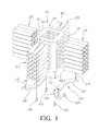
- FIG. 1 is a schematic exploded view showing a heat dissipation device with multiple heat conducting pipes according to a first embodiment of the present invention
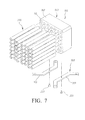
- FIG. 2 illustrates a schematic assembled view of the heat dissipation device shown in FIG. 1 and a schematic exploded view of the heat dissipation device and a carrier
- FIG. 3 illustrates a schematic cross-sectional view showing the assembly of the heat dissipation device and the carrier shown in FIG. 2
- FIG. 4 illustrates a schematic cross-sectional view showing the pipes of the heat dissipation device shown in FIG.
- a heat dissipation device with multiple heat conducting pipes wherein the heat dissipation device is mounted above a heat-generating element 410 (such as a CPU) disposed on a carrier 400 (such as a circuit board).
- the heat dissipation device includes a heat dissipation base 100 and a plurality of heat conducting pipes 200.
- the heat dissipation base 100 is formed from a thermally conductive metal (such as aluminum, copper or their alloys) or non-metal (such as graphite).
- the heat dissipation base 100 can be formed in any geometrical shapes and has at least one heat dissipation body 160.
- the heat dissipation base 100 is a hollow rectangular base 120 with four wall-shaped heat dissipation bodies 160 which are mutually connected. There are a plurality of heat conductive cavities 110 formed in the respective wall-shaped heat dissipation bodies 160.
- Each of the heat conducting pipes 200 is a tubular body which is also formed from a thermally conductive metal (such as aluminum, copper or their alloys) or non-metal (such as graphite).
- the heat conducting pipes 200 are disposed in heat conductive cavities 110 of the wall-shaped heat dissipation bodies 160, and protrude outwards from four respective sides of the wall-shaped heat dissipation bodies 160.
- the heat dissipation base 100 is fixed on a carrier 400 via a fixing unit 300.
- the fixing unit 300 includes two fixing brackets 310, a plurality of first fixing elements 320 and a plurality of second fixing elements 330, wherein the two fixing brackets 310 are located at two opposite positions of the bottom of the heat dissipation base 100; the fixing brackets 310 are fastened to the bottom of the heat dissipation base 100 via the first fixing elements 320, and are fastened to the carrier 400 via the second fixing elements 330, thereby making the bottom of the heat dissipation base 100 tightly contact the heat-generating element 410.
- the heat generated by the heat-generating element 410 is directly conducted to the hollow rectangular base 120, and is dissipated through the four wall-shaped heat dissipation bodies 160 and the hollow heat conducting pipes 200.
- the interior and exterior walls of the wall-shaped heat dissipation bodies 160 and those of the heat conducting pipes 200 can conduct heat dissipation at the same time, and the temperature differences between the internal and the external of the heat conducting pipes 200 also cause natural convection, thereby achieving excellent heat dissipation effect.
- each of the heat conducting pipes 200 further may have a plurality of axial grooves 210 formed in its interior wall for reinforcing the strength of the heat conducting pipes 200 for absorbing the changes thanks to thermal expansion or condensation of the heat conducting pipes 200 in heat conduction, thereby increasing heat dissipation area and rapidly introducing thermal flow, thus promoting heat dissipation efficiency.
- Each of the heat conducting pipes 200 also can be monolithically formed on the wall-shaped heat dissipation bodies 160, and has the same operation efficacy described above.
- FIG. 5 is a schematic exploded view showing a heat dissipation device with multiple heat conducting pipes according to a second embodiment of the present invention
- FIG. 6 illustrates a schematic assembled view of the heat dissipation device shown in FIG. 5 and a schematic exploded view of the heat dissipation device and a carrier.
- the heat dissipation device includes a heat dissipation base 100 and a plurality of heat conducting pipes 200, and further includes a fixing unit 300.
- the heat conducting pipes 200 and the fixing manner between the fixing unit 300 and the carrier 400 are the same for the first and second embodiments, but the heat dissipation base 100 of the second embodiment is a U-shaped heat dissipation base 130 with two wall-shaped heat dissipation bodies 160 which are opposite and connected to each other. There are a plurality of heat conductive cavities 110 formed in the wall-shaped heat dissipation bodies 160, and the heat conducting pipes 200 are disposed in the heat conductive cavities 110 respectively and protrude outwards from two respective sides of the wall-shaped heat dissipation bodies 160.
- the heat generated by the heat-generating element 410 is directly conducted to the U-shaped heat dissipation base 130, and is dissipated through the two wall-shaped heat dissipation bodies 160 and the hollow heat conducting pipes 200.
- the interior and exterior walls of the wall-shaped heat dissipation bodies 160 and those of the heat conducting pipes 200 can conduct heat dissipation at the same time, and the temperature differences between the internal and the external of the heat conducting pipes 200 also cause natural convection, thereby achieving excellent heat dissipation effect.
- each of the heat conducting pipes 200 also can be monolithically formed on the wall-shaped heat dissipation bodies 160, and has the same operation efficacy described above.
- FIG. 7 is a schematic exploded view showing a heat dissipation device with multiple heat conducting pipes according to a third embodiment of the present invention
- FIG. 8 illustrates a schematic assembled view of the heat dissipation device shown in FIG. 7 and a schematic exploded view of the heat dissipation device and a carrier.
- the heat dissipation device includes a heat dissipation base 100 and a plurality of heat conducting pipes 200, and further includes a fixing unit 300.
- the heat conducting pipes 200 and the fixing manner between the fixing unit 300 and the carrier 400 are the same for the first and third embodiments, but the heat dissipation base 100 of the third embodiment is a block-shaped heat dissipation base 140 with a block-shaped heat dissipation body 160.
- the heat conducting pipes 200 are disposed in the heat conductive cavities 110 respectively and protrude outwards from two opposite sides of the block-shaped heat dissipation body 160 respectively.
- the heat generated by the heat-generating element 410 is directly conducted to the block-shaped heat dissipation base 140, and is dissipated through the block-shaped heat dissipation bodies 160 and the hollow heat conducting pipes 200.
- the interior and exterior walls of the heat conducting pipes 200 can conduct heat dissipation at the same time, and the temperature differences between the internal and the external of the hollow heat conducting pipes 200 also cause natural convection, thereby achieving excellent heat dissipation effect.
- each of the heat conducting pipes 200 also can be monolithically formed on the wall-shaped heat dissipation bodies 160, and has the same operation efficacy described above.
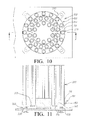
- FIG. 9 is a schematic exploded view showing a heat dissipation device with multiple heat conducting pipes according to a fourth embodiment of the present invention
- FIG. 10 illustrates a schematic assembled view of the heat dissipation device shown in FIG. 9 and a schematic exploded view of the heat dissipation device and a carrier
- FIG. 11 is a cross-sectional diagram viewed along line A-A of the heat dissipation device shown in FIG. 10 .
- the heat dissipation device includes a heat dissipation base 100 and a plurality of heat conducting pipes 200, and further includes a fixing unit 300.
- the heat conducting pipes 200 and the fixing manner between the fixing unit 300 and the carrier 400 are the same for the first and fourth embodiments, but the heat dissipation base 100 of the fourth embodiment is a disk-shaped heat dissipation base 140 with a disk-shaped heat dissipation body 160.
- the heat conducting pipes 200 are disposed in the heat conductive cavities 110 and protrude upwards from the disk-shaped heat dissipation body 160 respectively.
- the heat generated by the heat-generating element 410 is directly conducted to the disk-shaped heat dissipation base 150, and is dissipated through the disk-shaped heat dissipation bodies 160 and the hollow heat conducting pipes 200.
- the interior and exterior walls of the heat conducting pipes 200 can conduct heat dissipation at the same time, and the temperature differences between the internal and the external of the hollow heat conducting pipes 200 also cause natural convection, thereby achieving excellent heat dissipation effect.
- each of the heat conducting pipes 200 also can be monolithically formed on the wall-shaped heat dissipation bodies 160, and has the same operation efficacy described above.
- the dissipation device with multiple heat conducting pipes dissipates the heat generated by the heat-generating element by using heat conduction and natural convection via the heat conducting pipes, thus having an excellent double heat dissipation effect; and further, does not need additional fan and motor, thus avoiding the problems of high production cost, big volume, large power consumption and noise occurrence. Accordingly, the object of the present invention can be achieved.
Landscapes
- Engineering & Computer Science (AREA)
- Physics & Mathematics (AREA)
- General Engineering & Computer Science (AREA)
- Thermal Sciences (AREA)
- Mechanical Engineering (AREA)
- Sustainable Development (AREA)
- Life Sciences & Earth Sciences (AREA)
- Theoretical Computer Science (AREA)
- Microelectronics & Electronic Packaging (AREA)
- Human Computer Interaction (AREA)
- General Physics & Mathematics (AREA)
- Cooling Or The Like Of Electrical Apparatus (AREA)
- Cooling Or The Like Of Semiconductors Or Solid State Devices (AREA)
Applications Claiming Priority (1)
| Application Number | Priority Date | Filing Date | Title |
|---|---|---|---|
| TW099132219A TW201213760A (en) | 2010-09-23 | 2010-09-23 | Heat dissipation device with multiple heat pipes |
Publications (1)
| Publication Number | Publication Date |
|---|---|
| EP2434542A2 true EP2434542A2 (de) | 2012-03-28 |
Family
ID=45373854
Family Applications (1)
| Application Number | Title | Priority Date | Filing Date |
|---|---|---|---|
| EP11165402A Withdrawn EP2434542A2 (de) | 2010-09-23 | 2011-05-10 | Wärmeableitungsvorrichtung mit mehreren wärmeleitenden Rohren |
Country Status (4)
| Country | Link |
|---|---|
| US (1) | US20120073794A1 (de) |
| EP (1) | EP2434542A2 (de) |
| KR (1) | KR200467728Y1 (de) |
| TW (1) | TW201213760A (de) |
Families Citing this family (7)
| Publication number | Priority date | Publication date | Assignee | Title |
|---|---|---|---|---|
| US20150153113A1 (en) * | 2013-12-03 | 2015-06-04 | International Business Machines Corporation | Heat sink with air pathways through the base |
| CN109478541B (zh) * | 2016-07-01 | 2022-05-24 | 加贺株式会社 | 散热器及电子元件封装体 |
| CN106595367B (zh) * | 2016-12-08 | 2019-10-29 | 广东明路电力电子有限公司 | 组合式散热器 |
| SE542115C2 (en) | 2016-12-21 | 2020-02-25 | PrimeKey Solutions AB | A computer circuit board cooling arrangement |
| US10334760B1 (en) * | 2018-01-12 | 2019-06-25 | Jed A. Darland | System and method for helical cooling tower for efficient cooling |
| JP6640401B1 (ja) * | 2019-04-18 | 2020-02-05 | 古河電気工業株式会社 | ヒートシンク |
| CN117380768A (zh) * | 2023-12-11 | 2024-01-12 | 佛山市南海沃和五金模具机械有限公司 | 一种铝型材挤压机用循环冷却装置 |
Family Cites Families (8)
| Publication number | Priority date | Publication date | Assignee | Title |
|---|---|---|---|---|
| CA1063097A (en) * | 1976-01-26 | 1979-09-25 | David F. Fijas | Inner finned heat exchanger tube |
| JPH10321779A (ja) * | 1997-05-21 | 1998-12-04 | Hitachi Ltd | ヒートパイプ式冷却装置 |
| JP2001110956A (ja) * | 1999-10-04 | 2001-04-20 | Matsushita Electric Ind Co Ltd | 電子部品用の冷却機器 |
| US6747865B2 (en) * | 2001-04-27 | 2004-06-08 | Aavid Thermalloy, Llc | Heat sink for electronic components |
| AT413163B (de) * | 2001-12-18 | 2005-11-15 | Fotec Forschungs Und Technolog | Kühlvorrichtung für einen chip sowie verfahren zur herstellung |
| US6968890B1 (en) * | 2003-06-11 | 2005-11-29 | Apple Computer, Inc. | Heat sink |
| TWI274609B (en) * | 2006-01-13 | 2007-03-01 | Tai Sol Electronics Co Ltd | Combining method for heat pipe and heat dissipating block and combining structure thereof |
| KR20100089553A (ko) * | 2009-02-04 | 2010-08-12 | 잘만테크 주식회사 | 베이스 블록을 구비한 히트파이프 및 이를 제조하는 방법 |
-
2010
- 2010-09-23 TW TW099132219A patent/TW201213760A/zh unknown
-
2011
- 2011-05-10 EP EP11165402A patent/EP2434542A2/de not_active Withdrawn
- 2011-05-16 US US13/108,009 patent/US20120073794A1/en not_active Abandoned
- 2011-06-15 KR KR2020110005321U patent/KR200467728Y1/ko not_active Expired - Fee Related
Non-Patent Citations (1)
| Title |
|---|
| None |
Also Published As
| Publication number | Publication date |
|---|---|
| KR20120002299U (ko) | 2012-04-02 |
| TW201213760A (en) | 2012-04-01 |
| US20120073794A1 (en) | 2012-03-29 |
| KR200467728Y1 (ko) | 2013-07-03 |
Similar Documents
| Publication | Publication Date | Title |
|---|---|---|
| EP2434542A2 (de) | Wärmeableitungsvorrichtung mit mehreren wärmeleitenden Rohren | |
| US10285303B2 (en) | Electronic device with integrated passive and active cooling | |
| JP4391366B2 (ja) | ヒートパイプを備えたヒートシンクおよびその製造方法 | |
| US20110232877A1 (en) | Compact vapor chamber and heat-dissipating module having the same | |
| JP2023075207A (ja) | 冷却装置 | |
| US8365810B2 (en) | Active heat sink for use with electronic device | |
| US9255743B2 (en) | Finned heat dissipation module | |
| CN101142866B (zh) | 吸热构件、冷却装置及电子机器 | |
| CN106574625B (zh) | 冷却风扇 | |
| JP5667739B2 (ja) | ヒートシンクアセンブリ、半導体モジュール及び冷却装置付き半導体装置 | |
| US6816374B2 (en) | High efficiency heat sink/air cooler system for heat-generating components | |
| US20040035556A1 (en) | Heat-dissipating device with dissipating fins drivable to move within and ambient fluid | |
| JP4720688B2 (ja) | 電子制御装置の冷却装置 | |
| US20060185820A1 (en) | Radiator structure | |
| JP3170206U (ja) | マルチヒートパイプ式放熱装置 | |
| CN107534030A (zh) | 包括热管的散热器及相关方法 | |
| US20170031394A1 (en) | A heat-dissipating device including a vapor chamber and a radial fin assembly | |
| US20160070319A1 (en) | Heat sink | |
| US20190033930A1 (en) | Cooling device for use in heat dissipation associated with electronic components | |
| EP2659508B1 (de) | Wärmeableitungsvorrichtung und verfahren | |
| JP4229738B2 (ja) | ヒートパイプ式放熱ユニット | |
| CN211019806U (zh) | 一种用于电子器件的散热装置 | |
| CN216052952U (zh) | 一种用于台式计算机主体的散热保护装置 | |
| CN111594462B (zh) | 散热器和具有其的中央处理器 | |
| CN209895291U (zh) | 散热组件 |
Legal Events
| Date | Code | Title | Description |
|---|---|---|---|
| PUAI | Public reference made under article 153(3) epc to a published international application that has entered the european phase |
Free format text: ORIGINAL CODE: 0009012 |
|
| 17P | Request for examination filed |
Effective date: 20110510 |
|
| AK | Designated contracting states |
Kind code of ref document: A2 Designated state(s): AL AT BE BG CH CY CZ DE DK EE ES FI FR GB GR HR HU IE IS IT LI LT LU LV MC MK MT NL NO PL PT RO RS SE SI SK SM TR |
|
| AX | Request for extension of the european patent |
Extension state: BA ME |
|
| STAA | Information on the status of an ep patent application or granted ep patent |
Free format text: STATUS: THE APPLICATION IS DEEMED TO BE WITHDRAWN |
|
| 18D | Application deemed to be withdrawn |
Effective date: 20151201 |