EP2434604A1 - Stromversorgungsvorrichtung - Google Patents
Stromversorgungsvorrichtung Download PDFInfo
- Publication number
- EP2434604A1 EP2434604A1 EP20110181931 EP11181931A EP2434604A1 EP 2434604 A1 EP2434604 A1 EP 2434604A1 EP 20110181931 EP20110181931 EP 20110181931 EP 11181931 A EP11181931 A EP 11181931A EP 2434604 A1 EP2434604 A1 EP 2434604A1
- Authority
- EP
- European Patent Office
- Prior art keywords
- battery
- power source
- voltage
- alternating
- control section
- Prior art date
- Legal status (The legal status is an assumption and is not a legal conclusion. Google has not performed a legal analysis and makes no representation as to the accuracy of the status listed.)
- Ceased
Links
Images






Classifications
-
- B—PERFORMING OPERATIONS; TRANSPORTING
- B60—VEHICLES IN GENERAL
- B60L—PROPULSION OF ELECTRICALLY-PROPELLED VEHICLES; SUPPLYING ELECTRIC POWER FOR AUXILIARY EQUIPMENT OF ELECTRICALLY-PROPELLED VEHICLES; ELECTRODYNAMIC BRAKE SYSTEMS FOR VEHICLES IN GENERAL; MAGNETIC SUSPENSION OR LEVITATION FOR VEHICLES; MONITORING OPERATING VARIABLES OF ELECTRICALLY-PROPELLED VEHICLES; ELECTRIC SAFETY DEVICES FOR ELECTRICALLY-PROPELLED VEHICLES
- B60L53/00—Methods of charging batteries, specially adapted for electric vehicles; Charging stations or on-board charging equipment therefor; Exchange of energy storage elements in electric vehicles
- B60L53/10—Methods of charging batteries, specially adapted for electric vehicles; Charging stations or on-board charging equipment therefor; Exchange of energy storage elements in electric vehicles characterised by the energy transfer between the charging station and the vehicle
- B60L53/14—Conductive energy transfer
-
- B—PERFORMING OPERATIONS; TRANSPORTING
- B60—VEHICLES IN GENERAL
- B60L—PROPULSION OF ELECTRICALLY-PROPELLED VEHICLES; SUPPLYING ELECTRIC POWER FOR AUXILIARY EQUIPMENT OF ELECTRICALLY-PROPELLED VEHICLES; ELECTRODYNAMIC BRAKE SYSTEMS FOR VEHICLES IN GENERAL; MAGNETIC SUSPENSION OR LEVITATION FOR VEHICLES; MONITORING OPERATING VARIABLES OF ELECTRICALLY-PROPELLED VEHICLES; ELECTRIC SAFETY DEVICES FOR ELECTRICALLY-PROPELLED VEHICLES
- B60L53/00—Methods of charging batteries, specially adapted for electric vehicles; Charging stations or on-board charging equipment therefor; Exchange of energy storage elements in electric vehicles
- B60L53/20—Methods of charging batteries, specially adapted for electric vehicles; Charging stations or on-board charging equipment therefor; Exchange of energy storage elements in electric vehicles characterised by converters located in the vehicle
- B60L53/22—Constructional details or arrangements of charging converters specially adapted for charging electric vehicles
-
- B—PERFORMING OPERATIONS; TRANSPORTING
- B60—VEHICLES IN GENERAL
- B60L—PROPULSION OF ELECTRICALLY-PROPELLED VEHICLES; SUPPLYING ELECTRIC POWER FOR AUXILIARY EQUIPMENT OF ELECTRICALLY-PROPELLED VEHICLES; ELECTRODYNAMIC BRAKE SYSTEMS FOR VEHICLES IN GENERAL; MAGNETIC SUSPENSION OR LEVITATION FOR VEHICLES; MONITORING OPERATING VARIABLES OF ELECTRICALLY-PROPELLED VEHICLES; ELECTRIC SAFETY DEVICES FOR ELECTRICALLY-PROPELLED VEHICLES
- B60L58/00—Methods or circuit arrangements for monitoring or controlling batteries or fuel cells, specially adapted for electric vehicles
- B60L58/10—Methods or circuit arrangements for monitoring or controlling batteries or fuel cells, specially adapted for electric vehicles for monitoring or controlling batteries
- B60L58/18—Methods or circuit arrangements for monitoring or controlling batteries or fuel cells, specially adapted for electric vehicles for monitoring or controlling batteries of two or more battery modules
- B60L58/20—Methods or circuit arrangements for monitoring or controlling batteries or fuel cells, specially adapted for electric vehicles for monitoring or controlling batteries of two or more battery modules having different nominal voltages
-
- H—ELECTRICITY
- H02—GENERATION; CONVERSION OR DISTRIBUTION OF ELECTRIC POWER
- H02J—ELECTRIC POWER NETWORKS; CIRCUIT ARRANGEMENTS OR SYSTEMS FOR SUPPLYING OR DISTRIBUTING ELECTRIC POWER; SYSTEMS FOR STORING ELECTRIC ENERGY
- H02J1/00—Circuit arrangements for DC mains or DC distribution networks
- H02J1/08—Three-wire DC power distribution systems; Systems having more than three wires
-
- H—ELECTRICITY
- H02—GENERATION; CONVERSION OR DISTRIBUTION OF ELECTRIC POWER
- H02J—ELECTRIC POWER NETWORKS; CIRCUIT ARRANGEMENTS OR SYSTEMS FOR SUPPLYING OR DISTRIBUTING ELECTRIC POWER; SYSTEMS FOR STORING ELECTRIC ENERGY
- H02J1/00—Circuit arrangements for DC mains or DC distribution networks
- H02J1/08—Three-wire DC power distribution systems; Systems having more than three wires
- H02J1/082—DC supplies with two or more different DC voltage levels
-
- H—ELECTRICITY
- H02—GENERATION; CONVERSION OR DISTRIBUTION OF ELECTRIC POWER
- H02J—ELECTRIC POWER NETWORKS; CIRCUIT ARRANGEMENTS OR SYSTEMS FOR SUPPLYING OR DISTRIBUTING ELECTRIC POWER; SYSTEMS FOR STORING ELECTRIC ENERGY
- H02J7/00—Circuit arrangements for charging or discharging batteries or for supplying loads from batteries
- H02J7/50—Circuit arrangements for charging or discharging batteries or for supplying loads from batteries acting upon multiple batteries simultaneously or sequentially
-
- B—PERFORMING OPERATIONS; TRANSPORTING
- B60—VEHICLES IN GENERAL
- B60L—PROPULSION OF ELECTRICALLY-PROPELLED VEHICLES; SUPPLYING ELECTRIC POWER FOR AUXILIARY EQUIPMENT OF ELECTRICALLY-PROPELLED VEHICLES; ELECTRODYNAMIC BRAKE SYSTEMS FOR VEHICLES IN GENERAL; MAGNETIC SUSPENSION OR LEVITATION FOR VEHICLES; MONITORING OPERATING VARIABLES OF ELECTRICALLY-PROPELLED VEHICLES; ELECTRIC SAFETY DEVICES FOR ELECTRICALLY-PROPELLED VEHICLES
- B60L2210/00—Converter types
- B60L2210/10—DC to DC converters
- B60L2210/12—Buck converters
-
- B—PERFORMING OPERATIONS; TRANSPORTING
- B60—VEHICLES IN GENERAL
- B60L—PROPULSION OF ELECTRICALLY-PROPELLED VEHICLES; SUPPLYING ELECTRIC POWER FOR AUXILIARY EQUIPMENT OF ELECTRICALLY-PROPELLED VEHICLES; ELECTRODYNAMIC BRAKE SYSTEMS FOR VEHICLES IN GENERAL; MAGNETIC SUSPENSION OR LEVITATION FOR VEHICLES; MONITORING OPERATING VARIABLES OF ELECTRICALLY-PROPELLED VEHICLES; ELECTRIC SAFETY DEVICES FOR ELECTRICALLY-PROPELLED VEHICLES
- B60L2210/00—Converter types
- B60L2210/10—DC to DC converters
- B60L2210/14—Boost converters
-
- B—PERFORMING OPERATIONS; TRANSPORTING
- B60—VEHICLES IN GENERAL
- B60L—PROPULSION OF ELECTRICALLY-PROPELLED VEHICLES; SUPPLYING ELECTRIC POWER FOR AUXILIARY EQUIPMENT OF ELECTRICALLY-PROPELLED VEHICLES; ELECTRODYNAMIC BRAKE SYSTEMS FOR VEHICLES IN GENERAL; MAGNETIC SUSPENSION OR LEVITATION FOR VEHICLES; MONITORING OPERATING VARIABLES OF ELECTRICALLY-PROPELLED VEHICLES; ELECTRIC SAFETY DEVICES FOR ELECTRICALLY-PROPELLED VEHICLES
- B60L2210/00—Converter types
- B60L2210/30—AC to DC converters
-
- H—ELECTRICITY
- H02—GENERATION; CONVERSION OR DISTRIBUTION OF ELECTRIC POWER
- H02M—APPARATUS FOR CONVERSION BETWEEN AC AND AC, BETWEEN AC AND DC, OR BETWEEN DC AND DC, AND FOR USE WITH MAINS OR SIMILAR POWER SUPPLY SYSTEMS; CONVERSION OF DC OR AC INPUT POWER INTO SURGE OUTPUT POWER; CONTROL OR REGULATION THEREOF
- H02M1/00—Details of apparatus for conversion
- H02M1/0067—Converter structures employing plural converter units, other than for parallel operation of the units on a single load
- H02M1/007—Plural converter units in cascade
-
- Y—GENERAL TAGGING OF NEW TECHNOLOGICAL DEVELOPMENTS; GENERAL TAGGING OF CROSS-SECTIONAL TECHNOLOGIES SPANNING OVER SEVERAL SECTIONS OF THE IPC; TECHNICAL SUBJECTS COVERED BY FORMER USPC CROSS-REFERENCE ART COLLECTIONS [XRACs] AND DIGESTS
- Y02—TECHNOLOGIES OR APPLICATIONS FOR MITIGATION OR ADAPTATION AGAINST CLIMATE CHANGE
- Y02T—CLIMATE CHANGE MITIGATION TECHNOLOGIES RELATED TO TRANSPORTATION
- Y02T10/00—Road transport of goods or passengers
- Y02T10/60—Other road transportation technologies with climate change mitigation effect
- Y02T10/70—Energy storage systems for electromobility, e.g. batteries
-
- Y—GENERAL TAGGING OF NEW TECHNOLOGICAL DEVELOPMENTS; GENERAL TAGGING OF CROSS-SECTIONAL TECHNOLOGIES SPANNING OVER SEVERAL SECTIONS OF THE IPC; TECHNICAL SUBJECTS COVERED BY FORMER USPC CROSS-REFERENCE ART COLLECTIONS [XRACs] AND DIGESTS
- Y02—TECHNOLOGIES OR APPLICATIONS FOR MITIGATION OR ADAPTATION AGAINST CLIMATE CHANGE
- Y02T—CLIMATE CHANGE MITIGATION TECHNOLOGIES RELATED TO TRANSPORTATION
- Y02T10/00—Road transport of goods or passengers
- Y02T10/60—Other road transportation technologies with climate change mitigation effect
- Y02T10/7072—Electromobility specific charging systems or methods for batteries, ultracapacitors, supercapacitors or double-layer capacitors
-
- Y—GENERAL TAGGING OF NEW TECHNOLOGICAL DEVELOPMENTS; GENERAL TAGGING OF CROSS-SECTIONAL TECHNOLOGIES SPANNING OVER SEVERAL SECTIONS OF THE IPC; TECHNICAL SUBJECTS COVERED BY FORMER USPC CROSS-REFERENCE ART COLLECTIONS [XRACs] AND DIGESTS
- Y02—TECHNOLOGIES OR APPLICATIONS FOR MITIGATION OR ADAPTATION AGAINST CLIMATE CHANGE
- Y02T—CLIMATE CHANGE MITIGATION TECHNOLOGIES RELATED TO TRANSPORTATION
- Y02T10/00—Road transport of goods or passengers
- Y02T10/60—Other road transportation technologies with climate change mitigation effect
- Y02T10/72—Electric energy management in electromobility
-
- Y—GENERAL TAGGING OF NEW TECHNOLOGICAL DEVELOPMENTS; GENERAL TAGGING OF CROSS-SECTIONAL TECHNOLOGIES SPANNING OVER SEVERAL SECTIONS OF THE IPC; TECHNICAL SUBJECTS COVERED BY FORMER USPC CROSS-REFERENCE ART COLLECTIONS [XRACs] AND DIGESTS
- Y02—TECHNOLOGIES OR APPLICATIONS FOR MITIGATION OR ADAPTATION AGAINST CLIMATE CHANGE
- Y02T—CLIMATE CHANGE MITIGATION TECHNOLOGIES RELATED TO TRANSPORTATION
- Y02T10/00—Road transport of goods or passengers
- Y02T10/80—Technologies aiming to reduce greenhouse gasses emissions common to all road transportation technologies
- Y02T10/92—Energy efficient charging or discharging systems for batteries, ultracapacitors, supercapacitors or double-layer capacitors specially adapted for vehicles
-
- Y—GENERAL TAGGING OF NEW TECHNOLOGICAL DEVELOPMENTS; GENERAL TAGGING OF CROSS-SECTIONAL TECHNOLOGIES SPANNING OVER SEVERAL SECTIONS OF THE IPC; TECHNICAL SUBJECTS COVERED BY FORMER USPC CROSS-REFERENCE ART COLLECTIONS [XRACs] AND DIGESTS
- Y02—TECHNOLOGIES OR APPLICATIONS FOR MITIGATION OR ADAPTATION AGAINST CLIMATE CHANGE
- Y02T—CLIMATE CHANGE MITIGATION TECHNOLOGIES RELATED TO TRANSPORTATION
- Y02T90/00—Enabling technologies or technologies with a potential or indirect contribution to GHG emissions mitigation
- Y02T90/10—Technologies relating to charging of electric vehicles
- Y02T90/12—Electric charging stations
-
- Y—GENERAL TAGGING OF NEW TECHNOLOGICAL DEVELOPMENTS; GENERAL TAGGING OF CROSS-SECTIONAL TECHNOLOGIES SPANNING OVER SEVERAL SECTIONS OF THE IPC; TECHNICAL SUBJECTS COVERED BY FORMER USPC CROSS-REFERENCE ART COLLECTIONS [XRACs] AND DIGESTS
- Y02—TECHNOLOGIES OR APPLICATIONS FOR MITIGATION OR ADAPTATION AGAINST CLIMATE CHANGE
- Y02T—CLIMATE CHANGE MITIGATION TECHNOLOGIES RELATED TO TRANSPORTATION
- Y02T90/00—Enabling technologies or technologies with a potential or indirect contribution to GHG emissions mitigation
- Y02T90/10—Technologies relating to charging of electric vehicles
- Y02T90/14—Plug-in electric vehicles
Definitions
- the present invention relates to a power source device.
- a plug-in hybrid vehicle disclosed in Japanese Laid-Open Patent Publication No. 2008-312395 and electric vehicles generally use a high-voltage battery. Such vehicles are equipped with an on-vehicle charger for charging the high-voltage battery with an external commercial power source.
- a first battery is charged with an alternating-current power source at the same time as a second battery, the voltage of which is lower than that of the first battery, is supplied with electrical power from the alternating-current power source.
- a power source device that is capable of simultaneously charging a first battery with an alternating-current power source and supplying electrical power from the alternating-current power source to a second battery, the voltage of which is lower than the first battery.
- a power source device in accordance with one aspect of the present invention includes at least one first battery, at least one second battery, the voltage of which is lower than that of the first battery, and a transformer.
- the transformer has a primary coil, to which an alternating-current power source is connected, at least one first -secondary coil, to which the first battery is connected, and at least one second secondary coil, to which the second battery is connected.
- the power source device further includes a first power conversion circuit located between the primary coil of the transformer and the alternating-current power source, a second power conversion circuit located between the primary coil of the transformer and the first power conversion circuit, a third power conversion circuit located between the first secondary coil and the first battery, a rectification circuit located between the second secondary coil and the second battery, a voltage adjustment circuit located between the rectification circuit and the second battery, and a control section that charges the first battery using the alternating-current power source, and, simultaneously supplies electrical power to the second battery.
- the power source device is capable of simultaneously charging the first battery with the alternating-current power source and supplying electrical power to the second battery, the voltage of which is lower than the first battery.
- the control section includes a first control section.
- the first control section controls, on the side of the primary coil, the first power conversion circuit and the second power conversion circuit while implementing a feedback of the output to the first battery.
- the first control section charges the first battery using the alternating-current power source by, on the side of the first secondary coil of the transformer, controlling the third power conversion circuit.
- the first control circuit supplies, on the side of the second secondary coil, electrical power to the second battery from the alternating-current power source, while adjusting the output voltage to the second battery by the voltage adjustment circuit
- the first control section is capable of supplying electrical power to the second battery at the same time as charging the first battery.
- the control section includes a second control section.
- the second control section is configured to supply electrical power to the second battery from the first battery by, on the side of the first secondary coil, controlling the third power conversion circuit while implementing a feedback of the output to second battery.
- the control section includes a third control section.
- the third control section outputs alternating current to the side of the alternating-current power source from the first battery, and, simultaneously supplies electrical power to the second battery.
- the third control section is capable of simultaneously outputting alternating-current from the first battery and supplying electrical power from the alternating-current output to the low voltage second battery.
- the control section includes a fourth control section.
- the fourth control section generates, on the side of the primary coil of the transformer, alternating current using the second power conversion circuit and the first power conversion circuit by controlling the third power conversion circuit while implementing a feedback of the output from the alternating-current power source, and outputs alternating-current voltage to the side of the alternating-current power source from the first battery.
- the fourth control section supplies, on the side of the second secondary coil, electrical power from the first battery to the second battery.
- the fourth control section since the fourth control section implements a feedback of the output on the side of the alternating-current power source, the fourth control section is capable of simultaneously outputting alternating current and supplying electrical power to the second battery.
- control section further includes a fifth control section that implements a feedback of the output to the second battery.
- the fifth control section since the fifth control section implements feedback of both the output for the second battery and the alternating-current output, the fifth control section can control these outputs such that these do not surpass the rating of the transformer.
- the power source device in accordance with a seventh aspect, is designed for being mounted on a vehicle.
- the second battery is a complementary battery.
- a power source device for a vehicle in accordance with a ninth aspect of the present invention includes at least one first battery, at least one second battery, the voltage of which is lower than that of the first battery, a control circuit, a system main relay, and a charger.
- a device that is activated at least during charging is connected to the second battery.
- the control circuit is connected to the first battery via line, and the control circuit controls a load.
- the system main relay is provided on the line.
- the charger is connected to a part of the line between the system main relay and the first battery, and is capable of charging the first battery using an external alternating-current power source.
- the transformer has a primary coil, to which an alternating-current power source is connected, at least one first secondary coil, to which the first battery is connected, and at least one second secondary coil, to which the second battery is connected.
- the power source device further includes a first power conversion circuit located between the primary coil of the transformer and the alternating-current power source, a second power conversion circuit located between the primary coil of the transformer and the first power conversion circuit, a third power conversion circuit located between the first secondary coil and the first battery, a rectification circuit located between the second secondary coil and the second battery, a voltage adjustment circuit located between the rectification circuit and the second battery, and a control section that charges, in a state where the system main relay is open, the first battery using the alternating-current power source, and, simultaneously supplies electrical power to the second battery.
- charging of the first battery with the alternating-current power source is executed in a state where the system main relay is open.
- the control section charges the first battery with the alternating-current power source and simultaneously supplies electrical power to the second battery.
- the control section includes a first control section.
- the first control section controls, on the side of the primary coil, the first power conversion circuit and the second power conversion circuit while implementing a feedback of the output to the first battery.
- the first control section charges the first battery using the alternating-current power source by, on the side of the first secondary coil of the transformer, controlling the third power conversion circuit.
- the first control circuit supplies, on the side of the second secondary coil, electrical power to the second battery from the alternating-current power source, while adjusting the output voltage to the second battery by the voltage adjustment circuit
- the first control section is capable of supplying electrical power to the second battery at the same time as charging the first battery.
- the control section includes a second control section.
- the second control section is configured to supply electrical power to the second battery from the first battery by, on the side of the first secondary coil, controlling the third power conversion circuit while implementing a feedback of the output to second battery.
- the control section includes a third control section.
- the third control section outputs alternating current to the side of the alternating-current power source from the first battery, and, simultaneously supplies electrical power to the second battery.
- the third control section is capable of simultaneously outputting alternating-current from the first battery and supplying electrical power from the alternating-current output to the low voltage second battery.
- the control section includes a fourth control section.
- the fourth control section controls the third power conversion circuit while implementing a feedback of the output from the alternating-current power source.
- the fourth control section generates, on the side of the primary coil of the transformer, alternating current using the second power conversion circuit and the first power conversion circuit, thereby outputting alternating-current voltage to the side of the alternating-current power source from the first battery.
- the third power conversion circuit is configured to supply, on the side of the second secondary coil, electrical power to the second battery.
- the fourth control section is capable of simultaneously outputting alternating current to the alternating-current power source and supplying electrical power to the second battery.
- control section further includes a fifth control section that implements a feedback of the output to the second battery.
- the fifth control section since the fifth control section implements feedback of both the output for the second battery and the alternating-current output, the fifth control section can control these outputs such that these do not surpass the rating of the transformer.
- the present invention it Is possible to simultaneously charge the first battery with the alternating-current power source and supply electrical power from the alternating-current power source to the second battery, the voltage of which is lower than the first battery.
- Figs. 1 to 3 show a first embodiment of the present invention.
- Fig. 1 is a system diagram showing a power source device 10 according to the first embodiment.
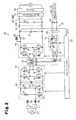
- Fig. 2 shows the circuit configuration of the power source device 10 of the first embodiment
- the power source device 10 is an on-vehicle power source device mounted on a plug-in hybrid vehicle or an electric car.
- the power source device 10 includes a high-voltage battery B1 serving as a first battery, a complementary battery 82 serving as a second battery the voltage of which is lower than that of the high-voltage battery B1, a power control unit (PCU) 20, a charger 30, a system main relay (SMR) 40, and a charger relay (CHR) 41.
- the PCU 20 includes a boost converter 21, an inverter 22, and a DCIDC converter 23.
- the boost converter 21 and the high-voltage battery B1 are connected to each other by a high-voltage line LH.
- a system main relay (SMR) 40 is arranged on a part of the high-voltage line LH between the boost converter 21 and the high-voltage battery B1.
- the charger 30 is connected to the system main relay 40 on the high-voltage line LH and the high-voltage battery B1 via the charger relay 41.
- the charger 30 is configured to be connected to a commercial power source (designated with reference numeral 67 in Fig. 2 ) serving as an external alternating-current power source via a charger connector 42.
- the charger 30 is capable of charging the high-voltage battery B1 with a commercial power source.
- the inverter 22 is connected to a driving motor (designated with reference sign M in Fig. 2 ) for moving the vehicle.
- the boost converter 21 raises the high voltage of the high-voltage battery B1, and the inverter 22 uses the raised voltage to operate the driving motor.
- the boost converter 21 and the inverter 22 each form a control circuit, are connected to the high-voltage battery B1 via high-voltage lines LH, and are configured to control the driving motor, which is a load.
- the DC/DC converter 23 of the PCU 20 is connected to a part of the high-voltage line LH between the system main relay 40 and the boost converter 21.
- the DC/DC converter 23 converts the high voltage of the high-voltage battery B1 into a low voltage for auxiliary devices.
- the DC/DC converter 23 is connected to a complementary battery B2 via a low-voltage line LL, and the complementary battery B2 is connected to auxiliary devices (43, 44) via another low-voltage line LL.
- the auxiliary devices include a power management ECU (PM-ECU) 43 and other auxiliary devices 44.
- the power management ECU 43 is configured, for example, to monitor the state of charge of the batteries B1, B2. In this manner, the power management ECU 43, which is activated at least during charging, is connected to the complementary battery B2.
- the charger 30 has a DC/DC converter 45.
- the complementary battery B2 is connected to the DC/DC converter 45.
- the DC/DC converter 45 is configured to supply electrical power to the complementary battery B2.
- the charger 30 includes, as shown from the left to the center of Fig. 2 , a filter 51, coils 52, 53, a first H-bridge circuit 54 serving as a first switching circuit, a capacitor 55, a second H-bridge circuit 56 serving as a second switching circuit, and a transformer 57.
- the transformer 57 includes a primary coil 57a, a first secondary coil 57b, and a second secondary coil 57c.
- the components 51 to 56 are located on the side of the primary coil 57a of the transformer 57.
- the charger 30 includes, as shown from the center to the right of Fig. 2 , a third H-bridge circuit 58 serving as a third switching circuit, a coil 59, a relay 60, and a capacitor 61.
- the charger 30 also includes, from the center lower part to the right of Fig. 2 , a rectifier 62, a voltage adjustment circuit 63 serving as a fourth switching circuit, a filter 65, and a control circuit 66 serving as a control section (the components 62, 63, 65 are collectively designated with reference numeral 45 in Fig. 1 ). These components 62 to 65 are located on the side of the second secondary coil 57c of the transformer 57.
- the first H-bridge circuit 54 which is capable of power factor correction, is located on the side of the primary coil 57a of the transformer 57.
- the first H-bridge circuit 54 includes diodes D1, D2 and switching elements S1, S2 each formed by a MOSFET. A parasitic diode is connected in parallel with each MOSFET.
- the anode terminal of the diode D1 and the drain terminal of the switching element S1 are connected to each other.
- the anode terminal of the diode D2 and the drain terminal of the switching element S2 are connected to each other.
- the cathode terminal of the diode D1 and the cathode terminal of the diode D2 are connected to each other.
- the source terminal of the switching element S1 and the source terminal of the switching element S2 are connected to each other.
- One end of the coil 52 is connected to a point between the diode D1 and the switching element S1.
- the other end of the coil 52 is connected to the commercial power source 67, which serves as an alternating-current power source, via the filter 51.
- One end of the coil 53 is connected to a point between the diode D2 and the switching element S2.
- the other end of the coil 53 is connected to the commercial power source 67 via the filter 51.
- the capacitor 55 is connected to a point between the cathode terminals of the diodes D1, D2 and the source terminals of the switching elements S1, S2.
- the second H-bridge circuit 56 which is capable of implementing DC/DC conversion, is located on the side of the primary coil 57a of the transformer 57.
- the second H-bridge circuit 56 is arranged between the primary coil 57a and the first H-bridge circuit 54.
- the second H-bridge circuit 56 has switching elements S3, S4, S5, S6 each formed by a MOSFET. A parasitic diode is connected in parallel with each MOSFET.
- the source terminal of the switching element S3 and the drain terminal of the switching element S4 are connected to each other.
- the source terminal of the switching element S5 and the drain terminal of the switching element S6 are connected to each other.
- the drain terminal of the switching element S3 and the drain terminal of the switching element S5 are connected to each other.
- the source terminal of the switching element S4 and the source terminal of the switching element S6 are connected to each other.
- the drain terminals of the switching elements S3, S5 and the source terminals of the switching elements S4, S6 are connected to the capacitor 55.
- a point between the switching element S3 and the switching element S4 is connected to one terminal of the primary coil 57a of the transformer 57.
- a point between the switching element S5 and the switching element S6 is connected to the other terminal of the primary coil 57a of the transformer 57.
- the commercial power source 67 is connected to the primary coil 57a of the transformer 57 via the second H-bridge circuit 56 and the first H-bridge circuit 54.
- the third H-bridge circuit 58 which is capable of implementing rectification, is located on the side of the first secondary coil 57b of the transformer 57.
- the third H-bridge circuit 58 has switching elements S7, S8, S9, S10 each formed by a MOSFET. A parasitic diode is connected in parallel with each MOSFET.
- the source terminal of the switching element S7 and the drain terminal of the switching element S8 are connected to each other.
- the source terminal of the switching element S9 and the drain terminal of the switching element S10 are connected to each other.
- the drain terminal of the switching element S7 and the drain terminal of the switching element S9 are connected to each other.
- the source terminal of the switching element S8 and the source terminal of the switching element S10 are connected to each other.
- a point between the switching element S7 and the switching element S8 is connected to one terminal of the first secondary coil 57b of the transformer 57.
- a point between the switching element S9 and the switching element S10 is connected to the other terminal of the first secondary coil 57b of the transformer 57.
- the drain terminals of the switching elements S7, S9 are connected to one electrode of the capacitor 61 via the coil 59.
- the source terminals of the switching elements S8, S10 are connected to the other electrode of the capacitor 61.
- the relay 60 is connected in parallel with the coil 59. When the relay 60 is activated, the drain terminals of the switching elements S7, S9 are connected with one electrode of the capacitor 61 via the coil 59. Alternatively, the relay 60 in the closed state directly connects the drain terminals of the switching elements S7, S9 with one electrode of the capacitor 61 without the coil 59 in between.
- the capacitor 61 is connected to the high-voltage battery B1, which serves as a first battery, via the charger relay 41.
- the first secondary coil 57b of the transformer 57 is connected to the high-voltage battery B1 via the third H-bridge circuit 58.
- the high-voltage battery B1 is connected to the boost converter 21 via the system main relay 40.
- the boost converter 21 is connected to the vehicle driving motor M via the inverter 22.
- the voltage adjustment circuit 63 which is capable of adjusting voltage, is located on the side of the second secondary coil 57c of the transformer 57.
- the voltage adjustment circuit 63 includes a switching element S11, a diode D3, and a coil 64.
- the switching element S11 ls formed by a MOSFET. A parasitic diode is connected in parallel with the MOSFET.
- the drain terminal of the switching element S11 is connected to one terminal of the second secondary coil 57c of the transformer 57 via the rectifier 62.
- the source terminal of the switching element S11 is connected to one end of the coil 64.
- the other end of the coil 64 is connected to the positive terminal of the complementary battery B2 via the filter 65.
- the source terminal of the switching element S11 is connected to the cathode terminal of the diode D3.
- the anode terminal of the diode D3 is connected to the other terminal of the second secondary coil 57c of the transformer 57 via the rectifier 62.
- the anode terminal of the diode D3 is connected to the negative terminal of the complementary battery B2 via the filter 65.
- the complementary battery B2 is connected auxiliary devices (the power management ECU 43 and other auxiliary devices 44).
- the second secondary coil 57c of the transformer 57 is connected to the complementary battery B2 via the voltage adjustment circuit 63. Also, the primary coil 57a of the transformer 57 is connected to the commercial power source 67. Thus, the transformer 57 has, on the side of the secondary coils, the first secondary coil 57b, which is connected to the high-voltage battery B1, and the second secondary coil 57c, which is connected to the complementary battery B2.
- the control circuit 66 controls the switching elements S1, S2 of the first H-bridge circuit 54, the switching elements S3, S4, S5, S6 of the second H-bridge circuit 56, the switching element S7, S8, S9, S10 of the third H-bridge circuit 58, and the switching element S11 of the voltage adjustment circuit 63.
- the control circuit 66 receives a feedback signal SGf1.
- the feedback signal SGf1 is a detection signal for detecting the output voltage from the charger relay 41 to the high-voltage battery B1.
- the first H-bridge circuit 54 corresponds to a first power conversion circuit provided between the primary coil 57a of the transformer 57 and the commercial power source 67.
- the second H-bridge circuit 56 corresponds to a second power conversion circuit provided between the primary coil 57a of the transformer 57 and the first power conversion circuit.
- the third H-bridge circuit 58 corresponds to a third power conversion circuit provided between the first secondary coil 57b and the high-voltage battery B1.
- the rectifier 62 corresponds to a rectification circuit provided between the second secondary coil 57c and the complementary battery B2.
- the voltage adjustment circuit 63 is provided between the rectifier 62 (rectification circuit) and the complementary battery B2.
- Fig. 3 shows operation of the power source device 10 as described above, that is, charging of the batteries B1. B2.
- the system main relay 40 is turned off (opened). Also, the charger relay 41 is turned on (closed).
- Altenating-current voltage from the commercial power source 67 is supplied, via the filter 51, to a power factor correction circuit formed by the coils 52 , 53, the first H-bridge circuit 54, and the capacitor 55.
- the switching elements S1, S2 of the first H-bridge circuit are alternately turned on and off by a control signal from the control circuit 66. Specifically, when the alternating-current voltage and the alternating current delivered to the first H-bridge circuit 54 are positive, the switching element S1 is turned on and off. When the switching element S1 is turned on, a current flows in the order of the coil 52 ⁇ the switching element S1 ⁇ the parasitic diode of the switching element S2 ⁇ the coil 53, so that electric energy is stored in the coils 52 , 53.
- the switching element S1 When the switching element S1 is turned off, a current flows in the order of the coil 52 ⁇ the diode D1 ⁇ the capacitor 55 ⁇ the parasitic diode of the switching element S2 ⁇ the coil 53 in a state where electric energy is stored in the coils 52, 53.
- the switching element S2 When the alternating-current voltage and the alternating current delivered to the first H-bridge circuit 54 are negative, the switching element S2 is turned on and off.
- the switching element S2 When the switching element S2 is turned on, a current flows in the order of the coil 53 ⁇ the switching element S2 ⁇ the parasitic diode of the switching element S1 ⁇ the coil 52, so that electric energy is stored in the coils 52 , 53.
- the alternating-current voltage is raised using the two coils 52, 53 and smoothed.
- power factor correction is implemented in which the phase and waveform of the alternating current are matched with or made similar to those of the alternating-current voltage.
- the duty cycle of the switching elements S1, S2 is changed (duty control is implemented) to smooth the alternating-current voltage, to raise the voltage by using the two coils 52, 53, and to implement power factor correction, in which the phase and waveform of the alternating current are matched with or made similar to those of the alternating-current voltage.
- the switching elements S3 to S6 of the second H-bridge circuit 56 are subjected to switching control by a control signal from the control circuit 66, so as to convert direct-current voltage supplied from the first H-bridge circuit 54 into alternating-current voltage.
- the converted alternating-current voltage is supplied to the primary coil 57a of the transformer 57, so that alternating-current voltage is induced in the first secondary coil 57b of the transformer 57.
- the switching elements S7 to S10 of the third H-bridge circuit 58 are controlled by a control signal from the control circuit 66, so as to convert the alternating-current voltage induced by the first secondary coil 57b into direct-current voltage. Then, the direct-current voltage is output to the high-voltage battery B1, so that the high-voltage battery B1 is charged.
- the control circuit 66 charges the high-voltage battery B1 by causing, on the side of primary coil 57a of the transformer 57, the first H-bridge circuit 54 to implement power factor correction and the second H-bridge circuit 56 to implement DC/DC conversion, and causing, on the side of the first secondary coil 57b of the transformer 57, the third H-bridge circuit 58 to implement rectification.
- the power factor correction circuit raises the voltage to 380 to 480 volts
- the high voltage output which is the output from the charger relay 41 to the high-voltage battery B1 is 144 to 197 volts.
- the charging of the high-voltage battery B1, that is, the output operation to a first output 1, is executed by sending the feedback signal SGf1 to the control circuit 66. Specifically, while the charger 30 implements a feedback of the output for the high-voltage battery B1 to the control circuit 66, the charging is executed such that the output voltage for the high-voltage battery B1 reaches a predetermined high voltage output (voltage).
- the alternating-current voltage induced by the second secondary coil 57c is converted into direct-current voltage by the rectifier 62.
- the direct-current voltage is supplied to the voltage adjustment circuit 63.
- the switching element S11 of the voltage adjustment circuit 63 is turned on and off by a control signal from the control circuit 66.
- the output voltage to the complementary battery B2 is adjusted to a constant value through the ON-OFF control, and the voltage adjustment circuit 63 outputs a low voltage of 13 to 14 volts, as a second output 2, to the complementary battery B2. Accordingly, the control circuit 66 supplies electrical power to the complementary battery B2.
- control circuit 66 outputs electrical power of the first output 1 (high voltage output) from the commercial power source 67 of the input to the high-voltage battery B1, and outputs electrical power of the second output 2 (complementary output) to the complementary battery B2.
- the complementary output is set to approximately 100 W.
- the control circuit 66 receives a feedback signal SGf1 showing a high voltage output for the first battery B1. That is, since the electrical power of the high voltage output for the first battery B1 is set at several kilo-Watts (kW), the high voltage output for the first battery B1 is larger than a complementary output for the second battery B2.
- control circuit 66 implements a feedback of control to the charger 30 based on the high voltage output for the first battery B1, sets the complementary output for the second battery B2 as a voltage within a range of 21-26 V, which depends on the high voltage output for the first battery B1 and is higher than the desired voltage (approximately 13-14 V) for the second battery B2, and adjusts the voltage for the second battery B2 via the voltage adjustment circuit 63.
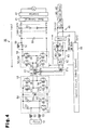
- Fig. 6 is a circuit diagram of a typical on-vehicle charger.
- a high-voltage battery 111 is connected to an external commercial power source 100 via a filter 101, coils 102, 103, a power factor correction H-bridge circuit 104, a capacitor 105, a DCIDC conversion H-bridge circuit 106, a transformer 107, a rectification H-bridge circuit 108, a coil 109, and a capacitor 110.
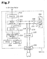
- Fig. 7 shows an example of a system configuration of a typical on-vehicle charger.
- an inverter 202 is connected to a high-voltage battery 200 via a high-voltage line LH and a boost converter 201.
- the inverter 202 drives the driving motor.
- a system main relay (SMR) 203 is located on the high-voltage line LH connecting the high-voltage battery 200 to the boost converter 201.
- a charger 205 is connected, via a charger relay (CHR) 204, to a part of the high voltage line LH that is between the system main relay 203 and the boost converter 201.
- the charger 205 is connected to an external commercial power source (a commercial power source 100 in Fig. 6 ) via a charger connector 206.
- a DC/DC converter 207 is connected to a part of the high-voltage line LH between the system main relay 203 and the boost converter 201.
- a complementary battery 208 is connected to the DC/DC converter 207 via a low-voltage line LL.
- Auxiliary devices (209, 210) are connected to the complementary battery 208 via a low-voltage line LL.
- the auxiliary devices include a power management ECU (PM-ECU) 209 and other auxiliary devices 210.
- the power management ECU 209 monitors the state of charge of the batteries 200, 208.
- the system main relay 203 and the charger relay 204 are closed, so that the charger 205 charges the high-voltage battery 200.
- the charger 205 needs to supply electrical power to components such as the power management ECU 209 and therefore needs to activate the DC/DC converter 207.
- the charger 30 of the present embodiment shown in Fig. 1 is connected to a point between the system main relay 40 and the high-voltage battery B1.
- the system main relay 40 is turned off so that the charger 30 does not supply electrical power to the inverter 22 or the DC/DC converter 23.
- the charger 30 supplies necessary electrical power to the power management ECU 43 during charging of the high-voltage battery B1. That is, unlike the typical charger shown in Fig. 6 , the present embodiment has the second secondary coil 57c (an output coil) of the transformer 57 as shown in Fig.
- the control circuit 66 can output electrical power to the complementary system. Accordingly, in the present embodiment, when electrical power is supplied to the power management ECU 43 during charging of the high-voltage battery B1, the DC/DC converter 23 does not need to be activated (the complementary system of the vehicle does not need to be activated). Accordingly, in the present embodiment, by opening the system main relay 40 during charging of the high-voltage battery B1, the control circuit 66 can reduce the consumed electrical power and improve the charging efficiency. That is, the control circuit 66 can cut unnecessary consumption of electrical power and charge the high-voltage battery B1 from the commercial power source (the alternating-current power source) 67 at a high charging efficiency.
- the commercial power source the alternating-current power source
- the control circuit 66 may implement feedback control using the AC output (the output to the alternating-current load 80). That is, while implementing a feedback of the output of alternating-current voltage, the control circuit 66 may implement DC/DC conversion using the third H-bridge circuit 58, rectification using the second H-bridge circuit, and generation of alternating current using the first H-bridge circuit 54.
- the switching elements may be formed by IGBTs, instead of MOSFETs.
- Fig. 1 shows a system configuration in which the voltage of the high-voltage battery B1 is increased by the boost converter 21 and is supplied to the inverter 22.
- the boost converter 21 may be omitted from the system, and the high-voltage battery B1 and the inverter 22 may be directly connected to each other via a high-voltage line LH to supply the voltage of the high-voltage battery B1 to the inverter 22.
- the power source device 10 is not limited to use for a vehicle.
- the power source device 10 may be used as a power source device for factories, offices, and households that charges the battery B1 using off-peak electrical power at night and uses the charged electrical power during the day.
- the illustrated embodiments may be applied to a power source device having a plurality of first batteries B1. That is, the illustrated embodiments can be applied to a power source device having at least one first battery.
- the illustrated embodiments may be applied to a power source device having a plurality of second batteries B2. That is, the illustrated embodiments can be applied to a power source device having at least one second battery, the voltage of which is lower than that of the first battery.
- Any transformer can be used as long as it includes at least one first secondary coil connected to the first battery B1 and at least one second secondary coil connected to the second battery B2.
- a power control device for a vehicle includes a first battery (B1), a second battery (B2), the voltage of which is lower than the voltage of the first battery, and a transformer (57).
- the transformer (57) includes a primary coil (57a), to which an alternating-current power source (67) is connected, a first secondary coil (57b), to which the first battery (B1) is connected, and at least one second secondary coil (57c), to which the second battery (B2) is connected.
- a rectification circuit (62) is located between the second secondary coil (57c) and the second battery (B2).
- a voltage adjustment circuit (63) is located between the rectification circuit (62) and the second battery (B2).
- a control section (66) charges the first battery (B1) using the alternating current power source (67), and, simultaneously supplies electrical power to the second battery.
Landscapes
- Engineering & Computer Science (AREA)
- Power Engineering (AREA)
- Transportation (AREA)
- Mechanical Engineering (AREA)
- Life Sciences & Earth Sciences (AREA)
- Sustainable Development (AREA)
- Sustainable Energy (AREA)
- Charge And Discharge Circuits For Batteries Or The Like (AREA)
- Dc-Dc Converters (AREA)
- Electric Propulsion And Braking For Vehicles (AREA)
- Secondary Cells (AREA)
- Inverter Devices (AREA)
Applications Claiming Priority (1)
| Application Number | Priority Date | Filing Date | Title |
|---|---|---|---|
| JP2010212452A JP5577986B2 (ja) | 2010-09-22 | 2010-09-22 | 電源装置および車載用電源装置 |
Publications (1)
| Publication Number | Publication Date |
|---|---|
| EP2434604A1 true EP2434604A1 (de) | 2012-03-28 |
Family
ID=44651435
Family Applications (1)
| Application Number | Title | Priority Date | Filing Date |
|---|---|---|---|
| EP20110181931 Ceased EP2434604A1 (de) | 2010-09-22 | 2011-09-20 | Stromversorgungsvorrichtung |
Country Status (5)
| Country | Link |
|---|---|
| US (1) | US8692512B2 (de) |
| EP (1) | EP2434604A1 (de) |
| JP (1) | JP5577986B2 (de) |
| KR (1) | KR101273995B1 (de) |
| CN (1) | CN102412604B (de) |
Cited By (12)
| Publication number | Priority date | Publication date | Assignee | Title |
|---|---|---|---|---|
| FR2987945A1 (fr) * | 2012-03-12 | 2013-09-13 | Peugeot Citroen Automobiles Sa | Dispositif de controle du rechargement rapide de batteries d'un systeme par commutation d'un circuit d'alimentation |
| FR2993728A1 (fr) * | 2012-07-20 | 2014-01-24 | Ies Synergy | Convertisseur reversible |
| WO2014118000A3 (de) * | 2013-01-31 | 2014-12-18 | Robert Bosch Gmbh | Energieübertragungsanordnung |
| DE102014200379A1 (de) * | 2014-01-13 | 2015-07-16 | Bayerische Motoren Werke Aktiengesellschaft | Ladevorrichtung für ein elektrisch angetriebenes Fahrzeug |
| BE1022153B1 (nl) * | 2014-08-07 | 2016-02-19 | Fcl Holding Nv | Methode voor het snelladen van loodzuur batterijen |
| FR3036864A1 (fr) * | 2015-05-29 | 2016-12-02 | Peugeot Citroen Automobiles Sa | Dispositif electrique multifonction |
| EP2963798A4 (de) * | 2013-02-26 | 2017-03-29 | Sumitomo Electric Industries, Ltd. | Dc-ac-umwandlungsvorrichtung und steuerschaltung |
| EP3339084A1 (de) * | 2016-12-23 | 2018-06-27 | ABB Schweiz AG | Elektrofahrzeugladestation mit trafo umfassend mehrere sekundäre spulen |
| US20180219471A1 (en) * | 2015-09-25 | 2018-08-02 | Sumitomo Electric Industries, Ltd. | Power supply device |
| JP2020507293A (ja) * | 2018-01-17 | 2020-03-05 | シェンヂェン ヴイマクス ニュー エネルギー カンパニー リミテッドShenzhen Vmax New Energy Co., Ltd. | ダブル出力ポート充電回路及びその制御方法 |
| WO2020229012A1 (de) * | 2019-05-15 | 2020-11-19 | Daimler Ag | Bordlader und verfahren zum laden einer hochvoltbatterie eines hochvoltbordnetzes oder einer niedervoltbatterie eines niedervoltbordnetzes |
| EP3874575A1 (de) * | 2018-10-29 | 2021-09-08 | Robert Bosch GmbH | Vorrichtung zur energieverteilung |
Families Citing this family (89)
| Publication number | Priority date | Publication date | Assignee | Title |
|---|---|---|---|---|
| DE102010042328A1 (de) * | 2010-10-12 | 2012-04-12 | Robert Bosch Gmbh | Verfahren zum Überwachen des Ladebetriebs eines Energiespeichers in einem Fahrzeug und Ladesystem zum Laden eines Energiespeichers in einem Fahrzeug |
| DE102010061763B4 (de) * | 2010-11-23 | 2024-09-12 | Robert Bosch Gmbh | Batterie |
| CN102097849B (zh) * | 2011-02-11 | 2013-11-06 | 蒋小平 | 直流电机电动车用感应器电能量回收装置 |
| KR101229441B1 (ko) * | 2011-03-18 | 2013-02-06 | 주식회사 만도 | 배터리 충전 장치 |
| US9969281B2 (en) * | 2011-11-22 | 2018-05-15 | Toyota Jidosha Kabushiki Kaisha | Vehicle and power transfer system |
| US9365115B2 (en) | 2012-01-20 | 2016-06-14 | Ford Global Technologies, Llc | System and method for vehicle power management |
| JP5831261B2 (ja) * | 2012-02-01 | 2015-12-09 | 株式会社デンソー | 電力伝送装置 |
| JP2013209017A (ja) * | 2012-03-30 | 2013-10-10 | Toyota Industries Corp | 電源回路 |
| JP5786787B2 (ja) * | 2012-04-16 | 2015-09-30 | 株式会社デンソー | 車載制御システム |
| JP6024209B2 (ja) * | 2012-05-29 | 2016-11-09 | 株式会社豊田自動織機 | バッテリの充電器制御システム |
| JP5575185B2 (ja) * | 2012-06-15 | 2014-08-20 | オムロンオートモーティブエレクトロニクス株式会社 | 車両用電源制御装置 |
| JP5661075B2 (ja) * | 2012-07-30 | 2015-01-28 | 三菱電機株式会社 | 充放電装置 |
| KR20140037302A (ko) * | 2012-09-11 | 2014-03-27 | 삼성전기주식회사 | 역률보상 회로, 그를 이용한 전원 공급 장치 및 진공 청소기 |
| US9114714B2 (en) * | 2012-09-27 | 2015-08-25 | Ford Global Technologies, Llc | High voltage charge pack |
| JP2014107933A (ja) * | 2012-11-27 | 2014-06-09 | Omron Automotive Electronics Co Ltd | 電源回路およびそれを用いた充電装置 |
| JP2014143817A (ja) * | 2013-01-23 | 2014-08-07 | Toyota Motor Corp | 車両の電源システム |
| KR101481277B1 (ko) * | 2013-06-10 | 2015-01-09 | 현대자동차주식회사 | 친환경 차량의 배터리 충전용 온보드 충전기 |
| DE102013212007B4 (de) * | 2013-06-25 | 2025-03-27 | Bayerische Motoren Werke Aktiengesellschaft | Elektrische Versorgung eines Fahrzeugs im Stand |
| US9713960B2 (en) * | 2013-09-26 | 2017-07-25 | Lear Corporation | On-board charger housekeeping power supply with automatic source transition |
| DE102014219478B4 (de) * | 2013-09-26 | 2019-11-07 | Lear Corporation | System und Verfahren zur bordseitigen Ladegerät-Betriebsenergieversorgung mit automatischem Quellenwechsel |
| JP6145022B2 (ja) * | 2013-10-22 | 2017-06-07 | 株式会社デンソー | 電力変換装置 |
| KR20150076843A (ko) * | 2013-12-27 | 2015-07-07 | 현대자동차주식회사 | 전기 자동차용 배터리 보호 회로 및 방법 |
| CN103754124B (zh) * | 2014-01-24 | 2016-03-30 | 中国重汽集团济南动力有限公司 | 一种电电混合纯电动城市客车控制系统 |
| US9682671B2 (en) * | 2014-06-10 | 2017-06-20 | Ford Global Technologies, Llc | Vehicle system with battery boost and bypass control |
| US9931951B2 (en) * | 2014-06-13 | 2018-04-03 | University Of Maryland | Integrated dual-output grid-to-vehicle (G2V) and vehicle-to-grid (V2G) onboard charger for plug-in electric vehicles |
| CN105226989A (zh) * | 2014-06-27 | 2016-01-06 | 联合汽车电子有限公司 | 新能源汽车的电力电子集成系统及其工作方法 |
| KR102255749B1 (ko) * | 2014-09-30 | 2021-05-25 | 현대모비스 주식회사 | 저전압 dc-dc 컨버터 일체형 충전 장치 |
| JP6397757B2 (ja) | 2014-12-26 | 2018-09-26 | 日立オートモティブシステムズ株式会社 | 電源装置 |
| DE102015207413B4 (de) * | 2015-04-23 | 2025-12-04 | Schaeffler Technologies AG & Co. KG | Leistungsschaltung zur Stromversorgung in einem elektrisch angetriebenen Fahrzeug |
| KR102178378B1 (ko) * | 2015-12-29 | 2020-11-13 | 한국전자기술연구원 | 일체형 전력변환장치 |
| CN105818690B (zh) * | 2016-03-02 | 2018-07-27 | 康迪电动汽车(上海)有限公司 | 高压配电装置及控制方法 |
| DE102016104541B4 (de) | 2016-03-11 | 2023-05-11 | Avl Software And Functions Gmbh | Ladesystem für Elektro- und Hybridfahrzeuge und ein Verfahren zum Laden mit einem Lade-system |
| CN105703622B (zh) * | 2016-03-14 | 2018-06-26 | Abb瑞士股份有限公司 | 直流-直流功率变换器及其方法 |
| US10457155B2 (en) * | 2016-09-09 | 2019-10-29 | Ford Global Technologies, Llc | System and method for charging electrified vehicle low-voltage battery |
| US10434898B2 (en) * | 2016-09-09 | 2019-10-08 | Ford Global Technologies, Llc | Electrified vehicle with expansion interface mechanism for interfacing with secondary electrical device |
| CN107070231B (zh) * | 2017-01-05 | 2024-04-09 | 上海蔚来汽车有限公司 | 具有多输入的混联变换器和使用其的充换电设施 |
| CN110192338A (zh) * | 2017-01-30 | 2019-08-30 | 古河电气工业株式会社 | 逆变器的启动时的控制方法和控制装置 |
| CN106936184A (zh) * | 2017-03-14 | 2017-07-07 | 深圳威迈斯电源有限公司 | 一种车载充电机和dcdc的集成电路 |
| KR102435023B1 (ko) * | 2017-05-19 | 2022-08-23 | 현대자동차주식회사 | 차량용 배터리 충전 제어시스템 |
| KR102454222B1 (ko) * | 2017-07-21 | 2022-10-17 | 현대자동차주식회사 | 전기 자동차 |
| KR102010512B1 (ko) * | 2017-09-21 | 2019-08-12 | 주식회사 아라 | 전기 차량용 충전 제어 장치 |
| DE102017123071B4 (de) * | 2017-10-05 | 2024-10-02 | Dr. Ing. H.C. F. Porsche Aktiengesellschaft | Versorgung von Niedervolt-Bordnetzen von Fahrzeugen mit elektrischem Antrieb |
| US11108225B2 (en) | 2017-11-08 | 2021-08-31 | Eaton Intelligent Power Limited | System, method, and apparatus for power distribution in an electric mobile application using a combined breaker and relay |
| US11070049B2 (en) | 2017-11-08 | 2021-07-20 | Eaton Intelligent Power Limited | System, method, and apparatus for power distribution in an electric mobile application using a combined breaker and relay |
| US11052784B2 (en) | 2017-11-08 | 2021-07-06 | Eaton Intelligent Power Limited | Power distribution unit and fuse management for an electric mobile application |
| US10946756B2 (en) * | 2017-11-14 | 2021-03-16 | Ford Global Technologies, Llc | Bidirectional integrated charger for a vehicle battery |
| JP7102773B2 (ja) * | 2018-02-22 | 2022-07-20 | トヨタ自動車株式会社 | 車両用電源システム |
| DE102018203263A1 (de) * | 2018-03-06 | 2019-09-12 | Audi Ag | Ladeeinrichtung für ein Kraftfahrzeug |
| KR102524192B1 (ko) * | 2018-03-21 | 2023-04-21 | 현대자동차주식회사 | 전기 자동차의 충전 장치 |
| CN110370962B (zh) * | 2018-04-10 | 2024-06-14 | 宇通客车股份有限公司 | 一种车载充电系统以及汽车 |
| JP6802826B2 (ja) * | 2018-09-13 | 2020-12-23 | 矢崎総業株式会社 | 車両電源装置 |
| JP7111580B2 (ja) * | 2018-10-26 | 2022-08-02 | 株式会社豊田中央研究所 | 電力変換装置 |
| JP2020108236A (ja) | 2018-12-27 | 2020-07-09 | 矢崎総業株式会社 | 電力変換装置 |
| WO2020152813A1 (ja) * | 2019-01-24 | 2020-07-30 | 株式会社日立産機システム | 電力変換システム |
| CN113228462A (zh) * | 2019-02-01 | 2021-08-06 | 住友电气工业株式会社 | 电源系统以及具备该电源系统的车辆 |
| US11689010B2 (en) | 2019-02-22 | 2023-06-27 | Eaton Intelligent Power Limited | Coolant fitting promoting turbulent flow |
| KR102692322B1 (ko) * | 2019-04-17 | 2024-08-07 | 현대자동차주식회사 | 통합형 컨버터 장치 |
| US11742688B2 (en) * | 2019-04-18 | 2023-08-29 | Delta Electronics (Shanghai) Co., Ltd. | Charging device and charging control method |
| US11588337B2 (en) | 2019-04-18 | 2023-02-21 | Delta Electronics (Shanghai) Co., Ltd. | Centralized charging cabinet provided with isolation area and charging area |
| EP4236048B1 (de) * | 2019-05-24 | 2026-05-20 | Huawei Digital Power Tech Co Ltd | Integriertes ladegerät und motorsteuerungssystem mit einem transformator und mehrstufigen stromrichtern |
| CN112970182A (zh) | 2019-06-28 | 2021-06-15 | 华为技术有限公司 | 具有高频中间交流和两个独立输出的交流-直流三电平转换系统 |
| WO2021009217A2 (en) | 2019-07-15 | 2021-01-21 | Eaton Intelligent Power Limited | Power distribution and circuit protection for a mobile application having a high efficiency inverter |
| KR102730545B1 (ko) * | 2019-08-06 | 2024-11-14 | 현대자동차주식회사 | 차량용 전력 변환 시스템 및 그 제어 방법 |
| US11407322B2 (en) * | 2019-09-05 | 2022-08-09 | Hong Kong Applied Science and Technology Research Institute Company, Limited | Smart power hub |
| CN111391958A (zh) * | 2020-03-26 | 2020-07-10 | 贵州量子动力科技有限公司 | 一种电动助力自行车用双电池联动装置 |
| EP4128509B1 (de) * | 2020-04-17 | 2024-09-18 | Huawei Technologies Co., Ltd. | Gleichstrom-gleichstrom-wandler mit freilaufschaltungen |
| FR3109678B1 (fr) * | 2020-04-27 | 2022-04-22 | Renault Sas | Chargeur de batteries pour véhicule automobile, véhicule et procédé de mise en œuvre associés |
| CN111641247B (zh) * | 2020-05-15 | 2022-03-08 | 华为数字能源技术有限公司 | 一种车载充电机的充电电路、车载充电机及充电控制方法 |
| WO2021251583A1 (ko) * | 2020-06-08 | 2021-12-16 | 서울과학기술대학교 산학협력단 | 저압 및 고압 일체용 충전 장치 |
| KR20220006190A (ko) * | 2020-07-08 | 2022-01-17 | 삼성전자주식회사 | 전자장치 및 전원공급장치 |
| CN113922482B (zh) * | 2020-07-10 | 2024-08-16 | 厦门厦杏摩托有限公司 | 电动车电源回路控制系统及其控制方法 |
| WO2022035550A1 (en) * | 2020-08-14 | 2022-02-17 | Cirrus Logic International Semiconductor Ltd. | Wireless power architecture with series-coupled power converters |
| CN112202342B (zh) * | 2020-11-03 | 2021-06-25 | 深圳威迈斯新能源股份有限公司 | 双向谐振变换器磁平衡电路及其控制方法 |
| CN112448601A (zh) | 2020-11-12 | 2021-03-05 | Oppo广东移动通信有限公司 | 电源提供装置、电路控制方法及供电系统 |
| CN112350567A (zh) * | 2020-11-12 | 2021-02-09 | Oppo广东移动通信有限公司 | 一种供电电源、电源提供方法及计算机存储介质 |
| DE102020214699A1 (de) * | 2020-11-23 | 2022-05-25 | Volkswagen Aktiengesellschaft | Elektrisches Netzwerk in einem Kraftfahrzeug |
| JP7578073B2 (ja) * | 2021-06-18 | 2024-11-06 | トヨタ自動車株式会社 | 電力供給ユニットおよび車両 |
| DE102021003879A1 (de) | 2021-07-27 | 2023-02-02 | Oleg Roj | Abwechslungsbatterien-motor |
| JP7410917B2 (ja) | 2021-11-05 | 2024-01-10 | 矢崎総業株式会社 | 車載充電器 |
| WO2023079327A1 (ja) * | 2021-11-08 | 2023-05-11 | 日産自動車株式会社 | 充放電制御方法及び充放電制御装置 |
| US12283892B2 (en) * | 2022-03-22 | 2025-04-22 | Rivian Ip Holdings, Llc | Low loss power converter control |
| EP4304074A1 (de) * | 2022-06-01 | 2024-01-10 | Milwaukee Electric Tool Corporation | Stromversorgung mit kaskadiertem wechselrichter |
| JP7218468B1 (ja) * | 2022-08-15 | 2023-02-06 | 正一 田中 | バッテリ用交流電流供給回路 |
| JP7765157B2 (ja) * | 2022-09-01 | 2025-11-06 | 正一 田中 | バッテリ用交流電流供給装置 |
| US20240322696A1 (en) * | 2023-03-21 | 2024-09-26 | Sensata Technologies, Inc. | Isolated solid-state active pre-charger |
| JPWO2024202684A1 (de) * | 2023-03-29 | 2024-10-03 | ||
| DE102023204720A1 (de) | 2023-05-22 | 2024-11-28 | GLOBE Fuel Cell Systems GmbH | Vorrichtung zum Umwandeln von Spannung |
| CN118651118A (zh) * | 2024-05-27 | 2024-09-17 | 东风商用车有限公司 | 车载储能系统及电动汽车 |
| EP4742525A1 (de) * | 2024-11-07 | 2026-05-13 | Abb Schweiz Ag | Hilfsversorgung für mittelspannungsgleichstromwandler mit einem in das wandlersystem integrierten hilfstransformator |
Citations (8)
| Publication number | Priority date | Publication date | Assignee | Title |
|---|---|---|---|---|
| JPH0965509A (ja) * | 1995-06-14 | 1997-03-07 | Toyota Autom Loom Works Ltd | 電気自動車用電池の充電方法及び電気自動車用充電器 |
| US5633577A (en) * | 1994-06-06 | 1997-05-27 | Nippondenso Co., Ltd. | Battery charging system for electric vehicles |
| EP1633029A2 (de) * | 2004-09-01 | 2006-03-08 | HONDA MOTOR CO., Ltd. | Ladesystem für einen auf Beinen laufenden Roboter |
| EP1916760A2 (de) * | 2006-10-24 | 2008-04-30 | TDK Corporation | Schaltnetzteil |
| EP1962415A2 (de) * | 2007-02-20 | 2008-08-27 | TDK Corporation | Schaltnetzteil |
| US20080316774A1 (en) * | 2007-06-15 | 2008-12-25 | Kabushiki Kaisha Toyota Jidoshokki | Power supply unit |
| WO2009116311A1 (ja) * | 2008-03-17 | 2009-09-24 | トヨタ自動車株式会社 | 電動車両 |
| WO2011141785A1 (en) * | 2010-05-14 | 2011-11-17 | Toyota Jidosha Kabushiki Kaisha | Power converter and vehicle provided with the same |
Family Cites Families (2)
| Publication number | Priority date | Publication date | Assignee | Title |
|---|---|---|---|---|
| US7746670B2 (en) * | 2006-10-04 | 2010-06-29 | Denso Corporation | Dual-transformer type of DC-to-DC converter |
| JP2010068568A (ja) * | 2008-09-09 | 2010-03-25 | Tamagawa Seiki Co Ltd | 電源回路 |
-
2010
- 2010-09-22 JP JP2010212452A patent/JP5577986B2/ja not_active Expired - Fee Related
-
2011
- 2011-09-16 CN CN201110282051.4A patent/CN102412604B/zh not_active Expired - Fee Related
- 2011-09-19 KR KR1020110093802A patent/KR101273995B1/ko not_active Expired - Fee Related
- 2011-09-20 US US13/237,629 patent/US8692512B2/en not_active Expired - Fee Related
- 2011-09-20 EP EP20110181931 patent/EP2434604A1/de not_active Ceased
Patent Citations (10)
| Publication number | Priority date | Publication date | Assignee | Title |
|---|---|---|---|---|
| US5633577A (en) * | 1994-06-06 | 1997-05-27 | Nippondenso Co., Ltd. | Battery charging system for electric vehicles |
| JPH0965509A (ja) * | 1995-06-14 | 1997-03-07 | Toyota Autom Loom Works Ltd | 電気自動車用電池の充電方法及び電気自動車用充電器 |
| EP1633029A2 (de) * | 2004-09-01 | 2006-03-08 | HONDA MOTOR CO., Ltd. | Ladesystem für einen auf Beinen laufenden Roboter |
| EP1916760A2 (de) * | 2006-10-24 | 2008-04-30 | TDK Corporation | Schaltnetzteil |
| EP1962415A2 (de) * | 2007-02-20 | 2008-08-27 | TDK Corporation | Schaltnetzteil |
| US20080316774A1 (en) * | 2007-06-15 | 2008-12-25 | Kabushiki Kaisha Toyota Jidoshokki | Power supply unit |
| JP2008312395A (ja) | 2007-06-15 | 2008-12-25 | Toyota Industries Corp | 電源装置 |
| WO2009116311A1 (ja) * | 2008-03-17 | 2009-09-24 | トヨタ自動車株式会社 | 電動車両 |
| EP2255990A1 (de) * | 2008-03-17 | 2010-12-01 | Toyota Jidosha Kabushiki Kaisha | Elektrofahrzeug |
| WO2011141785A1 (en) * | 2010-05-14 | 2011-11-17 | Toyota Jidosha Kabushiki Kaisha | Power converter and vehicle provided with the same |
Cited By (22)
| Publication number | Priority date | Publication date | Assignee | Title |
|---|---|---|---|---|
| FR2987945A1 (fr) * | 2012-03-12 | 2013-09-13 | Peugeot Citroen Automobiles Sa | Dispositif de controle du rechargement rapide de batteries d'un systeme par commutation d'un circuit d'alimentation |
| FR2993728A1 (fr) * | 2012-07-20 | 2014-01-24 | Ies Synergy | Convertisseur reversible |
| WO2014013058A3 (fr) * | 2012-07-20 | 2014-04-24 | Intelligent Electronic Systems | Convertisseur multi-directionel avec trois ports et un transformateur unique pour les voitures électriques |
| WO2014118000A3 (de) * | 2013-01-31 | 2014-12-18 | Robert Bosch Gmbh | Energieübertragungsanordnung |
| US10020658B2 (en) | 2013-01-31 | 2018-07-10 | Robert Bosch Gmbh | Power transmission arrangement |
| EP2963798A4 (de) * | 2013-02-26 | 2017-03-29 | Sumitomo Electric Industries, Ltd. | Dc-ac-umwandlungsvorrichtung und steuerschaltung |
| US9660517B2 (en) | 2013-02-26 | 2017-05-23 | Sumitomo Electric Industries, Ltd. | DC-AC conversion device, control circuit controlling operation of DC-AC conversion device, and control method for controlling operation of DC-AC conversion device |
| DE102014200379A1 (de) * | 2014-01-13 | 2015-07-16 | Bayerische Motoren Werke Aktiengesellschaft | Ladevorrichtung für ein elektrisch angetriebenes Fahrzeug |
| BE1022153B1 (nl) * | 2014-08-07 | 2016-02-19 | Fcl Holding Nv | Methode voor het snelladen van loodzuur batterijen |
| FR3036864A1 (fr) * | 2015-05-29 | 2016-12-02 | Peugeot Citroen Automobiles Sa | Dispositif electrique multifonction |
| US20180219471A1 (en) * | 2015-09-25 | 2018-08-02 | Sumitomo Electric Industries, Ltd. | Power supply device |
| US10811953B2 (en) * | 2015-09-25 | 2020-10-20 | Sumitomo Electric Industries, Ltd. | Power supply device |
| WO2018114414A1 (en) * | 2016-12-23 | 2018-06-28 | Abb Schweiz Ag | Electric vehicle charging station with medium voltage input |
| CN108778823A (zh) * | 2016-12-23 | 2018-11-09 | Abb瑞士股份有限公司 | 带中压输入的电动车辆充电站 |
| US10424436B2 (en) | 2016-12-23 | 2019-09-24 | Abb Schweiz Ag | Electric vehicle charging station with medium voltage input |
| CN108778823B (zh) * | 2016-12-23 | 2019-10-08 | Abb瑞士股份有限公司 | 带中压输入的电动车辆充电站 |
| EP3339084A1 (de) * | 2016-12-23 | 2018-06-27 | ABB Schweiz AG | Elektrofahrzeugladestation mit trafo umfassend mehrere sekundäre spulen |
| JP2020507293A (ja) * | 2018-01-17 | 2020-03-05 | シェンヂェン ヴイマクス ニュー エネルギー カンパニー リミテッドShenzhen Vmax New Energy Co., Ltd. | ダブル出力ポート充電回路及びその制御方法 |
| EP3533669A4 (de) * | 2018-01-17 | 2020-05-13 | Shenzhen Vmax Power Co., Ltd. | Ladeschaltung mit dualem ausgangsanschluss und steuerungsverfahren |
| EP3874575A1 (de) * | 2018-10-29 | 2021-09-08 | Robert Bosch GmbH | Vorrichtung zur energieverteilung |
| EP3874575B1 (de) * | 2018-10-29 | 2026-02-18 | Robert Bosch GmbH | Vorrichtung zur energieverteilung |
| WO2020229012A1 (de) * | 2019-05-15 | 2020-11-19 | Daimler Ag | Bordlader und verfahren zum laden einer hochvoltbatterie eines hochvoltbordnetzes oder einer niedervoltbatterie eines niedervoltbordnetzes |
Also Published As
| Publication number | Publication date |
|---|---|
| JP2012070518A (ja) | 2012-04-05 |
| KR20120031131A (ko) | 2012-03-30 |
| US20120068663A1 (en) | 2012-03-22 |
| US8692512B2 (en) | 2014-04-08 |
| JP5577986B2 (ja) | 2014-08-27 |
| CN102412604B (zh) | 2014-12-17 |
| CN102412604A (zh) | 2012-04-11 |
| KR101273995B1 (ko) | 2013-06-12 |
Similar Documents
| Publication | Publication Date | Title |
|---|---|---|
| US8692512B2 (en) | Power source device | |
| US9499060B2 (en) | Power conversion device | |
| US10763690B2 (en) | Vehicle-side charging circuit for a vehicle with electric drive, and method for operating a vehicle-side current converter, and use of at least one winding of a vehicle-side electric machine for intermediate storagectrical machine for buffer | |
| CN111641247B (zh) | 一种车载充电机的充电电路、车载充电机及充电控制方法 | |
| US9266441B2 (en) | Contactless power transfer system | |
| US10461553B2 (en) | Power source device | |
| US9425641B2 (en) | Battery charging apparatus | |
| CN107517595B (zh) | 双向非接触供电装置以及双向非接触供电系统 | |
| CN108933469B (zh) | 电气系统 | |
| CN110326183B (zh) | 充电装置以及车载电源装置 | |
| US8587252B2 (en) | System and method for digital control of a DC/DC power-converter device, in particular for automotive applications | |
| US20110156643A1 (en) | High-voltage battery charging system for use in electric vehicle | |
| JP2008312395A (ja) | 電源装置 | |
| KR102730545B1 (ko) | 차량용 전력 변환 시스템 및 그 제어 방법 | |
| EP2452848A1 (de) | Elektrische fahrzeugsteuerungsvorrichtung | |
| CN109641527A (zh) | 双向车载网络转换器和其运行方法 | |
| JP5461113B2 (ja) | 双方向コンバータ及びこれを用いた電気自動車の制御装置 | |
| JP6642119B2 (ja) | 充電器 | |
| JP6369509B2 (ja) | 電力変換回路 | |
| JP5412515B2 (ja) | 電源装置 | |
| CN114788155A (zh) | 组合式转换器电路 | |
| JP6032002B2 (ja) | 充電器 | |
| KR20210115215A (ko) | 저전압 직류 변환기 | |
| HK40070466A (en) | Combined converter circuit |
Legal Events
| Date | Code | Title | Description |
|---|---|---|---|
| PUAI | Public reference made under article 153(3) epc to a published international application that has entered the european phase |
Free format text: ORIGINAL CODE: 0009012 |
|
| 17P | Request for examination filed |
Effective date: 20110920 |
|
| AK | Designated contracting states |
Kind code of ref document: A1 Designated state(s): AL AT BE BG CH CY CZ DE DK EE ES FI FR GB GR HR HU IE IS IT LI LT LU LV MC MK MT NL NO PL PT RO RS SE SI SK SM TR |
|
| AX | Request for extension of the european patent |
Extension state: BA ME |
|
| 17Q | First examination report despatched |
Effective date: 20130125 |
|
| STAA | Information on the status of an ep patent application or granted ep patent |
Free format text: STATUS: THE APPLICATION HAS BEEN REFUSED |
|
| 18R | Application refused |
Effective date: 20150529 |