EP2436303A2 - Dispositif d'endoscope - Google Patents
Dispositif d'endoscope Download PDFInfo
- Publication number
- EP2436303A2 EP2436303A2 EP11183044A EP11183044A EP2436303A2 EP 2436303 A2 EP2436303 A2 EP 2436303A2 EP 11183044 A EP11183044 A EP 11183044A EP 11183044 A EP11183044 A EP 11183044A EP 2436303 A2 EP2436303 A2 EP 2436303A2
- Authority
- EP
- European Patent Office
- Prior art keywords
- light
- section
- light source
- amount
- narrow band
- Prior art date
- Legal status (The legal status is an assumption and is not a legal conclusion. Google has not performed a legal analysis and makes no representation as to the accuracy of the status listed.)
- Withdrawn
Links
Images


Classifications
-
- A—HUMAN NECESSITIES
- A61—MEDICAL OR VETERINARY SCIENCE; HYGIENE
- A61B—DIAGNOSIS; SURGERY; IDENTIFICATION
- A61B1/00—Instruments for performing medical examinations of the interior of cavities or tubes of the body by visual or photographical inspection, e.g. endoscopes; Illuminating arrangements therefor
- A61B1/04—Instruments for performing medical examinations of the interior of cavities or tubes of the body by visual or photographical inspection, e.g. endoscopes; Illuminating arrangements therefor combined with photographic or television appliances
- A61B1/043—Instruments for performing medical examinations of the interior of cavities or tubes of the body by visual or photographical inspection, e.g. endoscopes; Illuminating arrangements therefor combined with photographic or television appliances for fluorescence imaging
-
- A—HUMAN NECESSITIES
- A61—MEDICAL OR VETERINARY SCIENCE; HYGIENE
- A61B—DIAGNOSIS; SURGERY; IDENTIFICATION
- A61B1/00—Instruments for performing medical examinations of the interior of cavities or tubes of the body by visual or photographical inspection, e.g. endoscopes; Illuminating arrangements therefor
- A61B1/00002—Operational features of endoscopes
- A61B1/00004—Operational features of endoscopes characterised by electronic signal processing
- A61B1/00009—Operational features of endoscopes characterised by electronic signal processing of image signals during a use of endoscope
- A61B1/000094—Operational features of endoscopes characterised by electronic signal processing of image signals during a use of endoscope extracting biological structures
-
- A—HUMAN NECESSITIES
- A61—MEDICAL OR VETERINARY SCIENCE; HYGIENE
- A61B—DIAGNOSIS; SURGERY; IDENTIFICATION
- A61B1/00—Instruments for performing medical examinations of the interior of cavities or tubes of the body by visual or photographical inspection, e.g. endoscopes; Illuminating arrangements therefor
- A61B1/04—Instruments for performing medical examinations of the interior of cavities or tubes of the body by visual or photographical inspection, e.g. endoscopes; Illuminating arrangements therefor combined with photographic or television appliances
- A61B1/045—Control thereof
-
- A—HUMAN NECESSITIES
- A61—MEDICAL OR VETERINARY SCIENCE; HYGIENE
- A61B—DIAGNOSIS; SURGERY; IDENTIFICATION
- A61B1/00—Instruments for performing medical examinations of the interior of cavities or tubes of the body by visual or photographical inspection, e.g. endoscopes; Illuminating arrangements therefor
- A61B1/06—Instruments for performing medical examinations of the interior of cavities or tubes of the body by visual or photographical inspection, e.g. endoscopes; Illuminating arrangements therefor with illuminating arrangements
- A61B1/063—Instruments for performing medical examinations of the interior of cavities or tubes of the body by visual or photographical inspection, e.g. endoscopes; Illuminating arrangements therefor with illuminating arrangements for monochromatic or narrow-band illumination
-
- A—HUMAN NECESSITIES
- A61—MEDICAL OR VETERINARY SCIENCE; HYGIENE
- A61B—DIAGNOSIS; SURGERY; IDENTIFICATION
- A61B1/00—Instruments for performing medical examinations of the interior of cavities or tubes of the body by visual or photographical inspection, e.g. endoscopes; Illuminating arrangements therefor
- A61B1/06—Instruments for performing medical examinations of the interior of cavities or tubes of the body by visual or photographical inspection, e.g. endoscopes; Illuminating arrangements therefor with illuminating arrangements
- A61B1/0638—Instruments for performing medical examinations of the interior of cavities or tubes of the body by visual or photographical inspection, e.g. endoscopes; Illuminating arrangements therefor with illuminating arrangements providing two or more wavelengths
-
- A—HUMAN NECESSITIES
- A61—MEDICAL OR VETERINARY SCIENCE; HYGIENE
- A61B—DIAGNOSIS; SURGERY; IDENTIFICATION
- A61B1/00—Instruments for performing medical examinations of the interior of cavities or tubes of the body by visual or photographical inspection, e.g. endoscopes; Illuminating arrangements therefor
- A61B1/06—Instruments for performing medical examinations of the interior of cavities or tubes of the body by visual or photographical inspection, e.g. endoscopes; Illuminating arrangements therefor with illuminating arrangements
- A61B1/0653—Instruments for performing medical examinations of the interior of cavities or tubes of the body by visual or photographical inspection, e.g. endoscopes; Illuminating arrangements therefor with illuminating arrangements with wavelength conversion
-
- A—HUMAN NECESSITIES
- A61—MEDICAL OR VETERINARY SCIENCE; HYGIENE
- A61B—DIAGNOSIS; SURGERY; IDENTIFICATION
- A61B1/00—Instruments for performing medical examinations of the interior of cavities or tubes of the body by visual or photographical inspection, e.g. endoscopes; Illuminating arrangements therefor
- A61B1/06—Instruments for performing medical examinations of the interior of cavities or tubes of the body by visual or photographical inspection, e.g. endoscopes; Illuminating arrangements therefor with illuminating arrangements
- A61B1/0655—Control therefor
-
- A—HUMAN NECESSITIES
- A61—MEDICAL OR VETERINARY SCIENCE; HYGIENE
- A61B—DIAGNOSIS; SURGERY; IDENTIFICATION
- A61B1/00—Instruments for performing medical examinations of the interior of cavities or tubes of the body by visual or photographical inspection, e.g. endoscopes; Illuminating arrangements therefor
- A61B1/06—Instruments for performing medical examinations of the interior of cavities or tubes of the body by visual or photographical inspection, e.g. endoscopes; Illuminating arrangements therefor with illuminating arrangements
- A61B1/0661—Endoscope light sources
-
- H—ELECTRICITY
- H04—ELECTRIC COMMUNICATION TECHNIQUE
- H04N—PICTORIAL COMMUNICATION, e.g. TELEVISION
- H04N23/00—Cameras or camera modules comprising electronic image sensors; Control thereof
- H04N23/50—Constructional details
- H04N23/555—Constructional details for picking-up images in sites, inaccessible due to their dimensions or hazardous conditions, e.g. endoscopes or borescopes
-
- H—ELECTRICITY
- H04—ELECTRIC COMMUNICATION TECHNIQUE
- H04N—PICTORIAL COMMUNICATION, e.g. TELEVISION
- H04N23/00—Cameras or camera modules comprising electronic image sensors; Control thereof
- H04N23/70—Circuitry for compensating brightness variation in the scene
- H04N23/74—Circuitry for compensating brightness variation in the scene by influencing the scene brightness using illuminating means
Definitions
- the present invention relates to an endoscope device capable of performing a special light observation using specific narrow band light and wide band light such as white illumination light.
- an endoscope device capable of performing a so-called special light observation has been used, where the special light observation obtains information on a tissue at a desired depth of a living body by emitting specific narrow band light (narrow band light) to a mucous tissue of the living body.
- This type of endoscope device may simply visualize living body information, which cannot be obtained from an ordinary observation image, by emphasizing a lesion and a microstructure of a surface layer of a new blood vessel generated at, for example, a mucous layer or a lower mucous layer.
- narrow band blue light B
- the microstructure or the microscopic blood vessel of the surface layer of the tissue may be observed in more detail, so that the lesion may be more accurately diagnosed.
- an invasion depth of light in the thickness direction of the living body tissue is dependent on the wavelength of the light.
- the blue light (B) having a short wavelength the light only reaches the vicinity of the surface layer due to the absorbing and scattering characteristics of the living body tissue, and is absorbed and scattered at the depth range, so that the light may be observed as returned light mainly including information on the surface layer tissue.
- the green light G having a wavelength longer than that of the B light the light reaches a position deeper than the range the B light reaches, and is absorbed and scattered at this range, so that the light may be observed as returned light mainly including information on the intermediate layer tissue and the surface layer tissue.
- red light (R) having a wavelength longer than that of the G light
- the light reaches a deeper position of the tissue, and is absorbed and scattered at this range, so that the light may be observed as returned light mainly including information on the deep layer tissue and the intermediate layer tissue.
- image signals obtained by receiving light using an imaging sensor such as a CCD after emitting the B light, the G light, and the R light respectively mainly include information on the surface layer tissue, information on the intermediate layer tissue and the surface layer tissue, and information on the deep layer tissue and the intermediate layer tissue.
- the narrow band light of blue (B) suitable for observing the surface layer tissue and the narrow band green light G suitable for observing the intermediate layer tissue and the surface layer tissue are used as the narrow band light emitted to the living body tissue without using the narrow band red light R mainly suitable for observing the intermediate layer tissue and the deep layer tissue of the living body tissue.
- B-image signal B narrow band data
- G-image signal G narrow band data
- the G-image signal (G narrow band data) obtained by the imaging sensor is allocated to R-image data of a color image through a predetermined coefficient
- the B-image signal (B narrow band data) is allocated to G-image data and B-image data of a color image through a predetermined coefficient
- a quasi-color image including 3-ch (channel) color image data is created, and the image is displayed on a monitor or the like.
- the image processing of the narrow band light mode converting two GB-image signals obtained by receiving the returned light of the narrow band light using the imaging sensor into RGB color image data for a quasi-color display on a display unit is different from the image processing of the ordinary light mode converting three RGB-image signals obtained by receiving the returned light of the ordinary light using the imaging sensor into RGB color image data for a color display on a display unit.
- the image processing is performed only by using the G-image signal and the B-image signal without using the R-image signal (R narrow band data), and an observation is performed by displaying the quasi-color image on the monitor or the like.
- the G-image signal is allocated to the R-image data
- the B-image signal is allocated to the G-image data and the B-image data
- the quasi-color image including 3-ch color data is created, and the image is displayed on the monitor or the like.
- the quasi-color image displayed on the monitor or the like mainly includes the B-image signal (B narrow band data) including information on the surface layer tissue
- the microstructure or the microscopic blood vessel of the surface layer tissue may be displayed in more detail, and the microstructure and the microscopic blood vessel of the surface layer tissue may be easily observed (refer to JP 3559755 B and JP 3607857 B ).
- the microstructure or the microscopic blood vessels of the surface layer tissue which may be easily brightly seen, may be displayed as an image, but there is a problem in that it is more difficult to see the microstructure or the microscopic blood vessels of the surface layer tissue as the distance increases.
- the irradiation light amount is generally increased in order to handle such a problem.
- the increase in irradiation light amount particularly, an increase in special light amount. Accordingly, a problem arises in that the color tint of the captured image changes when compensating for insufficient special light amount using ordinary light.
- an endoscope device comprising: a first light source section that emits narrow band light having a predetermined wavelength bandwidth narrowed in accordance with spectral spectrum characteristics of a structure and a component of a living body as a subject; a second light source section that emits wide band light having a wide wavelength bandwidth including a visible region; a light source control section that controls emission of the narrow band light from the first light source section and the wide band light from the second light source section and light emission amounts of the narrow band light and the wide band light; an imaging section that captures an image of the subject using returned light in which at least one of the narrow band light and the wide band light emitted to the subject is returned from the subject and outputs captured image information; a light amount calculating section that calculates a capturing light amount of the captured image from the captured image information captured by the imaging section; a light amount ratio calculating section that calculates a ratio between a light emission amount of the narrow band light emitted from the
- the light source control section perform different controls in accordance with the capturing light amount calculated by the light amount calculating section such that: in case of a capturing operation using the narrow band light, emission of the wide band light from the second light source section is stopped and then the light emission amount of the narrow band light emitted from the first light source section is controlled and, when the light emission amount of the narrow band light becomes maximal, the wide band light is emitted from the second light source section and then the light emission amount of the wide band light is controlled, and in case of a capturing operation without using the narrow band light, emission of the narrow band light from the first light source section is stopped and then the light emission amount of the wide band light emitted from the second light source section is controlled.
- the light source control section control at least one of the light emission amount of the narrow band light from the first light source section and the light emission amount of the wide band light from the second light source section so that the capturing light amount calculated by the light amount calculating section become a predetermined value or more necessary for capturing the subject regardless of a distance between the imaging section and the subject.
- the light source control section control at least one of the light emission amount of the narrow band light from the first light source section and the light emission amount of the wide band light from the second light source section so that the capturing light amount calculated by the light amount calculating section substantially become equal to a predetermined value necessary for capturing the subject regardless of a distance between the imaging section and the subject.
- the light source control section control such that: when the emission of the wide band light from the second light source section be stopped and the narrow band light be emitted from the first light source section, the light emission amount of the narrow band light emitted from the first light source section be controlled so that the capturing light amount of the captured image calculated by the light amount calculating section become equal to or more than a predetermined value necessary for capturing the subject, when the capturing light amount do not reach the predetermined value even when the light emission amount of the narrow band light become maximal, the narrow band light be emitted from the first light source section at a maximal light amount, and the wide band light be emitted from the second light source section and then, the light emission amount of the wide band light be controlled so that the capturing light amount become equal to or more than the predetermined value, and the narrow band light be emitted from the first light source section and the wide band light be emitted from the second light source section, the light emission amount of the wide band
- the light source control section controls the light emission amount of the wide band light emitted from the second light source section so that the capturing light amount of the captured image calculated by the light amount calculating section becomes the predetermined value or more.
- the light source control section allow the imaging section to perform a capturing operation using only the narrow band light in a near-distance capturing operation in which the distance between the imaging section and the subject be smaller than the predetermined distance, and the light source control section allow the imaging section to perform a capturing operation using the narrow band light and the wide band light in a far-distance capturing operation in which the distance between the imaging section and the subject be larger than the predetermined distance.
- the light source control section allow the imaging section to perform a capturing operation using only the wide band light.
- the light amount ratio calculating section calculate a ratio between the light emission amount of the narrow band light and the light emission amount of the wide band light based on values of electrical currents passed through the first light source section and the second light source section by the light source control section.
- the image processing section include a color conversion coefficient table representing a relationship between a color conversion coefficient for adjusting a color tint of the captured image and a ratio between the light emission amount of the narrow band light and the light emission amount of the wide band light obtained in advance so that a white balance of the captured image do not change, in order to change the image processing condition, and the image processing section select the color conversion coefficient from the color conversion coefficient table based on the ratio between the light emission amount of the narrow band light and the light emission amount of the wide band light calculated by the light amount calculating section.
- an endoscope device including: a first light source section that emits first illumination light excellently acquiring information on a surface layer tissue of a living body as a subject; a second light source section that emits second illumination light mainly including white light excellently illuminating the subject; a light source control section that controls emission of the first illumination light from the first light source section and the second illumination light from the second light source section and a light emission amount of the first illumination light and the second illumination light; an imaging section that captures an image of the subject by returning light from at least one of the first illumination light and the second illumination light emitted to the subject and outputs captured image information; a light amount calculating section that calculates a capturing light amount of the captured image from the captured image information obtained by the imaging section; a light amount ratio calculating section that calculates a ratio between the light emission amount of the first illumination light emitted from the first light source section and the light emission amount of the second illumination light emitted from the second light source section controlled by the light source control section; and an image processing
- the light emission conditions of the special light source and the white illumination light source are sequentially controlled so that the light amount of the returned light detected by the imaging element becomes a predetermined value or more at all times, and the image processing condition for adjusting the color tint (hue) of the image processing section is changed in accordance with the light emission conditions of the special light source and the white illumination light source. Accordingly, in the case of performing the ordinary observation and the special light observation, for example, even when the capturing operation is performed at a position far from or close to a lesion, the operator does not need to intentionally adjust the color tint of the captured image and the light emission conditions of the light sources while observing the captured image.
- a captured image with a stable color tint may be obtained at all times regardless of the capturing distance.
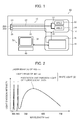
- Fig. 1 is a block diagram schematically illustrating an example of an entire configuration of the endoscope device of the embodiment of the invention.
- an endoscope device 10 of the invention includes an endoscope 12, a light source unit 14, a processor 16, and an input and output unit 18.
- the light source unit 14 and the processor 16 constitute a control device of the endoscope 12, and the endoscope 12 is optically connected to the light source unit 14 and is electrically connected to the processor 16.
- the processor 16 is electrically connected to the input and output unit 18.
- the input and output unit 18 includes a display section (monitor) 38 that outputs and displays image information or the like, a recording section (recording device) 42 (refer to Fig.
- an input section (mode switching section) 40 that serves as a UI (user interface) receiving an input operation of function setting or mode switching for an ordinary observation mode (referred to as an ordinary light mode) or a special light observation mode (referred to as a special light mode).
- the endoscope 12 is an electronic endoscope that includes an illumination optical system emitting illumination light from the front end thereof and an imaging optical system capturing an image of a subject observation region. Furthermore, although not shown in the drawings, the endoscope 12 includes an endoscope insertion section that is inserted into a subject, an operation section that is used to curve the front end of the endoscope insertion section or perform an observation, and a connector that attachably and detachably connects the endoscope 12 to the light source unit 14 and the processor 16 of the control device. Furthermore, although not shown in the drawings, the operation section and the endoscope insertion section are provided with various channels such as a clamp channel through which a tissue extracting treatment tool or the like is inserted or air and water supply channels.
- the front end of the endoscope 12 is provided with an irradiation port 28A that emits light to a subject observation region.
- the irradiation port 28A is provided with an imaging element (sensor) 26 such as a CCD (Charge Coupled Device) image sensor or a CMOS (Complementary Metal-Oxide Semiconductor) image sensor that constitutes an illumination optical system, includes a fluorescent body 24 constituting a white light source, and acquires image information of the subject observation region at a light receiving portion 28B adjacent to the irradiation port 28A.
- an imaging element (sensor) 26 such as a CCD (Charge Coupled Device) image sensor or a CMOS (Complementary Metal-Oxide Semiconductor) image sensor that constitutes an illumination optical system, includes a fluorescent body 24 constituting a white light source, and acquires image information of the subject observation region at a light receiving portion 28B adjacent to the irradiation port 28A.
- the irradiation port 28A of the endoscope 12 is provided with a cover glass or a lens (not shown) constituting an irradiation optical system
- the light receiving portion 28B is provided with a cover glass or a lens (not shown) constituting an illumination optical system
- a light receiving surface of the imaging element 26 of the light receiving portion 28B is provided with an objective lens (not shown) constituting an imaging optical system.
- the endoscope insertion section may be freely curved by the operation of the operation section, may be curved at an arbitrary angle in an arbitrary direction in accordance with a portion or the like of the subject where the endoscope 12 is used, and may direct the observation direction of the irradiation port 28A and the light receiving portion 28B, that is, the imaging element 26 to a desired observation portion.
- the imaging element 26 be a complementary color sensor or an imaging sensor including a color filter (for example, an RGB color filter or a complementary color filter) in the light receiving region, but it is more desirable to use an RGB color image sensor.
- a color filter for example, an RGB color filter or a complementary color filter
- the light source unit 14 includes a light source, that is, a blue-violet laser beam source (405LD) 32 that has a central wavelength of 405 nm and is used as a special light source in the special light mode and a blue laser beam source (445LD) 34 that has a central wavelength of 445 nm and is used as a white illumination light source, for both the ordinary light mode and the special light mode.
- a blue-violet laser beam having a central wavelength of 405 nm output from the blue-violet laser beam source 32 has an excellent detecting property for a structure and a component of a living body since it is narrow band light having a wavelength bandwidth narrowed in accordance with the emission spectrum of the structure and components of the living body.
- the light emission from the semiconductor light emitting elements of the light sources 32 and 34 is individually controlled by a light source control section 48 (refer to Fig. 3 ), and the light emission condition of each of the light sources 32 and 34, that is, the light amount ratio between the light emitted from the blue-violet laser beam source 32 and the light emitted from the blue laser beam source 34 may be freely changed.
- the blue-violet laser beam source 32 and the blue laser beam source 34 a broad area type InGaN laser diode, an InGaNAs laser diode, or a GaNAs laser diode may be used. Further, the light source may be configured as a light emitter such as a light emitting diode.
- the laser beams emitted from the light sources 32 and 34 are respectively input to optical fibers 22 by a condensing lens (not shown), and are transmitted to the connector through a multiplexer (not shown). Furthermore, the invention is not limited thereto, and a configuration may be adopted in which the laser beams output from the light sources 32 and 34 are directly transmitted to the connector without using the multiplexer.
- the laser beam which is obtained by multiplexing the blue-violet laser beam having a central wavelength of 405 nm and the blue laser beam having a central wavelength of 445 nm and is transmitted to the connector, is propagated to the front end of the endoscope 12 by the optical fiber 22 constituting the illumination optical system. Then, the blue laser beam emits fluorescence by exciting the fluorescent body 24 as a wavelength converting member disposed at the light emission end of the optical fiber 22 of the front end of the endoscope 12. Further, a part of the blue laser beam is directly transmitted through the fluorescent body 24. Then, a part of the blue-violet laser beam excites the fluorescent body 24, but most of the beam is transmitted through the fluorescent body 24 without any excitation, so that it becomes illumination light of a narrow band wavelength (so-called narrow band light).
- narrow band light narrow band light
- the optical fiber 22 is a multi-mode fiber, and an example thereof includes a thin fiber cable having a core diameter of 105 ⁇ m, a cladding diameter of 125 ⁇ m, and a diameter, including a protective layer as an outer coat, of ⁇ 0.3 to 0.5 mm.
- the fluorescent body 24 includes a plurality of types of fluorescent bodies (for example, a YAG-based fluorescent body or a fluorescent body of BAM (BaMgAl 10 O 17 ) or the like) absorbing a part of the blue laser beam and the blue-violet laser beam and emitting green to yellow light by being excited. Accordingly, white (quasi-white) illumination light is obtained by combining green to yellow excitation light using the blue laser beam and the blue-violet laser beam as excitation light and the blue laser beam and the blue-violet laser beam not absorbed by the fluorescent body 24 and transmitted therethrough.
- fluorescent bodies for example, a YAG-based fluorescent body or a fluorescent body of BAM (BaMgAl 10 O 17 ) or the like
- the semiconductor light emitting element emitting the blue laser beam having a central wavelength of 445 nm is used as an excitation light source, it is possible to obtain high-intensity white light with high light emitting efficiency, easily adjust the intensity of white light, and suppress a change in the color temperature and chromaticity of the white light as small as possible.
- the fluorescent body 24 may prevent flickering generated when displaying a dynamic image or overlapping of noise disturbing an imaging operation due to speckles generated by coherent of a laser beam. Further, it is desirable that the fluorescent body 24 be formed in consideration of a difference in refractive index between a fluorescent material constituting the fluorescent body and a fixing and solidifying resin forming a filling material.
- the particle diameter of the material of the fluorescent body and the filling material has small absorbing and great scattering with respect to light of an infrared region. Accordingly, it is possible to improve a scattering effect without degrading light intensity with respect to light of a red or infrared region, and reduce optical loss.
- Fig. 2 is a graph illustrating emission spectrums of the blue-violet laser beam output from the blue-violet laser beam source 32, the blue laser beam output from the blue laser beam source 34, and the light obtained by converting the wavelength of the blue laser beam through the fluorescent body 24.
- the blue-violet laser beam is depicted by the emission line (profile A) having a central wavelength of 405 nm, is narrow band light of the invention, and is mainly used as special light. Further, the blue laser beam is depicted by the emission line having a central wavelength of 445 nm.
- the excitation and emission light obtained from the fluorescent body 24 using the blue laser beam substantially has a wavelength bandwidth of 450 nm to 700 nm, and has a spectral intensity distribution in which light emission intensity increases.
- the profile B formed by the excitation and emission light and the blue laser beam the above-described quasi-white light is formed, and is mainly used as ordinary light.
- the fluorescent body 24 is also excited by the blue-violet laser beam and emits excitation and emission light with a light amount of 1/8 of the case of the blue laser beam, so that it forms quasi-white light.
- the blue-violet laser beam with a central wavelength of 405 nm emitted from the blue-violet laser beam source 32 and the excitation and emission light from the fluorescent body 24 include a large amount of the component of the narrow band light of 405 nm and are excellently used to observe the surface layer tissue (acquire information on the surface layer tissue), but include a small amount of the excitation and emission light from the fluorescent body 24. For this reason, the light emission amount of the white light used for capturing the background may not be increased. Accordingly, when the distance up to the subject is close, the light emission amount of the white light for the background is sufficient. However, when the distance up to the subject is far, the light emission amount of the white light is not sufficient in the excitation and emission light generated by the blue-violet laser beam.
- the blue laser beam with a central wavelength of 445 nm emitted from the blue laser beam source 34 and the excitation and emission light from the fluorescent body 24 are not excellent for observing the surface layer tissue compared to the blue-violet laser beam, but may strongly excite the fluorescent body 24 and increase the light emission amount of the white light for the background. Accordingly, even when the distance up to the subject is far, the light amount of the white light may be sufficiently ensured.
- the blue laser beam source 34 may be used to compensate the light amount of the white light formed by the blue-violet laser beam from the blue-violet laser beam source 32.
- the white light mentioned in the invention is not precisely limited to the light including all wavelength components of the visible light, but may include, for example, light of a specific wavelength such as R, G, and B including the above-described quasi-white light.
- a specific wavelength such as R, G, and B
- light including green to red wavelength components or light including blue to green wavelength components is included.
- the light emission intensities of the profile A and the profile B are controlled to be relatively increased and decreased by the light source control section 48, so that an illumination port with an arbitrary luminance balance may be generated. Furthermore, in the endoscope device 10 of the invention, only the light of the profile B is used in the ordinary light mode, and in principle, the light of the profile A and the excitation and emission light (not shown) based on the light of the profile A are used in the special light mode. Here, in order to compensate the insufficient light amount of the excitation and emission light (not shown), the light of the profile B is overlapped.
- the image signal of the captured image output from the imaging element 26 after the imaging operation is input to an image processing system 36 of the processor 16 through a scope cable 30.
- the image signal of the image captured by the imaging element 26 in this manner is processed by the signal processing system including the image processing system 36 of the processor 16, is output to a monitor 38 or a recording device 42, and is provided for the user's observation.
- Fig. 3 is a block diagram illustrating the signal processing system for respective sections including a specific configuration of an example of the process of the endoscope device of the invention.
- the signal processing system of the endoscope device 10 includes the signal processing system of the endoscope 12, the signal processing system of the light source unit 14, the signal processing system (image processing system 36) of the processor 16, the monitor 38 of the input and output unit 18, the input section (mode switching section) 40, and the recording device 42.
- the signal processing system of the endoscope 12 is a signal processing system of an image signal of a captured image from the imaging element 26 after the imaging operation, and includes a CDS and AGC circuit 44 that performs a correlated double sampling (CDS) or an automatic gain control (AGC) on a captured image signal as an analog signal and an A/D converter 46 that converts the analog image signal subjected to the sampling and the gain control in the CDS and AGC circuit 44 into a digital image signal.
- the digital image signal A/D converted in the A/D converter 46 is input to the image processing system 36 of the processor 16 through the connector.
- the signal processing system of the light source unit 14 includes the light source control section 48 that performs a light amount control and an on/off control of the blue laser beam source (445LD) 34 and the blue-violet laser beam source (405LD) 32.
- the light source control section 48 turns on the blue-violet laser beam source 32 in response to a light source on signal generated when starting the operation of the endoscope device 10, controls an on and off state of the blue-violet laser beam source 32 in response to a signal output from the mode switching section 40 to switch to the special light mode or the ordinary light mode, or controls the light emission amount of the blue-violet laser beam source 32 and the blue laser beam source 34, that is, the value of the current flowing to the light sources 32 and 34 in accordance with the luminance value of the image calculated from a light amount calculating unit 50 to be described later.
- the light source control section 48 serves as a light amount ratio changing unit together with the light amount calculating unit 50 and the light amount ratio calculating section 56 to be described later on the basis of the ratio between the calculated light emission amount and the light emission amount so as to change a light emission condition, that is, a light amount ratio between both light sources 32 and 34.
- the signal processing system of the processor 16 is the image processing system 36 (refer to Fig. 1 ), and includes the light amount calculating unit 50, a DSP (digital signal processor) 52, a noise removing circuit 54, a light amount ratio calculating section 56, an image processing switching section (switch) 60, an ordinary light image processing unit 62, a special light image processing unit 64, and an image display signal generating unit 66.
- the light amount calculating unit 50 includes the light amount calculating unit 50, a DSP (digital signal processor) 52, a noise removing circuit 54, a light amount ratio calculating section 56, an image processing switching section (switch) 60, an ordinary light image processing unit 62, a special light image processing unit 64, and an image display signal generating unit 66.
- DSP digital signal processor
- the light amount calculating unit 50 uses the digital image signal input from the A/D converter 46 of the endoscope 12 through the connector, and calculates the light amount of the returned light received at the imaging element 26, that is, the luminance value of the captured image. Then, the calculated light amount is output to the light source control section 48 and the light amount ratio calculating section 56.
- the light source control section 48 controls the light emission amount of the blue-violet laser beam source (405LD) 32 and the blue laser beam source (445LD) 34 so that the light amount of the returned light become the predetermined value or more.
- the position between the front end of the endoscope and the subject is fixed, and the blue laser beam source (445LD) 34 is stopped to increase the light emission amount of the blue-violet laser beam source (405LD) 32 (refer to Fig. 4A ).
- the subject When the calculated light amount of the returned light becomes the predetermined value or more, the subject is captured at the light emission amount. Further, when the light emission amount of the blue-violet laser beam source (405LD) 32 becomes maximal, but the light amount of the returned light is not sufficient, as shown in Fig. 4B , the blue laser beam source (445LD) 34 is turned on to increase the light emission amount as a whole. When the calculated light amount of the returned light becomes the predetermined value or more, the subject is captured at the light emission amount.
- the white illumination light source (here, the blue laser beam source (445LD) 34) is used for the ordinary light observation. Accordingly, in many cases, one lamp, two lamps, or three lamps are used, whereby the light emission amount may be sufficiently increased.
- the irradiation light amount of the blue laser beam source (445LD) 34 increases, the light amount is sufficient.
- the tone of the captured image changes, and the information of the captured image for the microstructure of the surface layer blood vessel subjected to the special light observation may not be visually obtained. Accordingly, there is a need to perform appropriately necessary contents of the image processing in the image processing unit to be described later.
- the light emission amount is controlled by fixing the position between the front end of the endoscope and the subject in order to obtain the light amount of the returned light necessary for a capturing operation, but the position of the front end of the endoscope may be moved with the fixed light emission amount.
- the light emission amount of the blue-violet laser beam source (405LD) 32 may be fixed to a predetermined value, and the endoscope may be moved to adjust the position between the front end of the endoscope and the subject so that the light amount of the returned light becomes the predetermined value or more.
- the light emission amount of the blue-violet laser beam source (405LD) 32 may be set to be maximal in advance, the light emission amount of the blue laser beam source (445LD) 34 may be fixed to a predetermined value, and as described above, the endoscope may be moved to adjust the position between the front end of the endoscope and the subject so that the light amount of the returned light becomes the predetermined value or more.
- the light amount ratio calculating section 56 calculates the light amount ratio between the light emission amounts of the 405LD 32 and the 445LD 34 by receiving information on a current value of a current driving the blue-violet laser beam source (405LD) 32 and the blue laser beam source (445LD) 34 using the light source control section 48.
- the calculated light amount ratio is output to a special light color converting section 74 to be described later of the special light image processing unit 64.
- a signal processing system may be configured in a manner such that the light amount and the light amount ratio of the 405LD 32 and the 445LD 34 are output to the CDS and AGC circuit 44 and the gain of the CDS and AGC circuit 44 obtaining the white balance on the basis of the information of the light amount and the light amount ratio so as to change the electric gain of the imaging element 26.
- the information of the gain for determining the white balance is output to the image processing unit 62 and the special light image processing unit 64, so that it is used for the color conversion and the special light color conversion.
- the DSP 52 (digital signal processor) performs a gamma correction process and a color correction process on the digital image signal output from the A/D converter 46 after detecting the light source light amount at the light amount calculating unit 50.
- the noise removing circuit 54 removes noise from the digital image signal subjected to the gamma correction process and the color correction process in the DSP 52 by performing, for example, a noise removing method in the image processing such as a moving-average method or a median filtering method.
- the digital image signal input from the endoscope 12 to the processor 16 is subjected to a pre-process such as a gamma correction process, a color correction process, and a noise removing process at the DSP 52 and the noise removing circuit 54.
- a pre-process such as a gamma correction process, a color correction process, and a noise removing process at the DSP 52 and the noise removing circuit 54.
- the image processing switching section 60 is a switch that switches the transmission destination of the digital image signal subjected to a pre-process to the special light image processing unit 64 or the ordinary light image processing unit 62 at the rear stage on the basis of the instruction (switching signal) of the mode switching section (input section) to be described later.
- the digital image signal before the image processing using the ordinary light image processing unit 62 and the special light image processing unit 64 is referred to as an image signal
- the digital image signal before and after the image processing is referred to as image data.
- the ordinary light image processing unit 62 is a unit that performs ordinary light image processing suitable for the digital image signal subjected to the pre-process using the white light (profile B) of the fluorescent body 24 and the 445LD in the ordinary light mode, and includes a color converting section 68, a color emphasizing section 70, and a structure emphasizing section 72.
- the color converting section 68 performs a color conversion process such as a three-dimensional LUT process, a grayscale conversion process, and a three by three matrix process on the digital image signals of RGB three channels subjected to the pre-process, so that it is converted into RGB image data subjected to the color conversion process.
- a color conversion process such as a three-dimensional LUT process, a grayscale conversion process, and a three by three matrix process on the digital image signals of RGB three channels subjected to the pre-process, so that it is converted into RGB image data subjected to the color conversion process.
- the color emphasizing section 70 is used to emphasize the blood vessel so as to be easily viewed by making a difference in color tint or hue between the blood vessel and the mucous in the screen, and performs a process on the RGB image data subjected to the color conversion process while seeing the screen.
- the process is, for example, a process that emphasizes a difference in color tint (hue) between the blood vessel and the mucous from the average value while seeing the average color tint of the entire screen.
- the structure emphasizing section 72 performs a structure emphasizing process such as a sharpening process or an outline emphasizing process on the RGB image data subjected to the color emphasizing process.
- the RGB image data subjected to the structure emphasizing process in the structure emphasizing section 72 is input as the RGB image data subjected to the ordinary light image processing from the ordinary light image processing unit 62 to the image display signal generating unit 66.
- the special light image processing unit 64 is a unit that performs special light image processing suitable for the digital image signal subjected to the pre-process using the white light (profile B) from the fluorescent body 24 and the 445LD 34, and the blue-violet laser beam (profile A) from the 405LD 34 in the special light mode, and includes a special light color converting section 74, a color emphasizing section 76, and a structure emphasizing section 78.
- the special light color converting section 74 allocates the G-image signal of the digital image signals of the RGB three channels subjected to the pre-process to the R-image data through a predetermined coefficient, and allocates the B-image signal to the G-image data and B-image data through a predetermined coefficient so as to generate the RGB image data. Then, the generated RGB image data is subjected to a color conversion process such as a three-dimensional LUT process, a grayscale conversion process, and a three by three matrix process as in the color converting section 68.
- a color conversion process such as a three-dimensional LUT process, a grayscale conversion process, and a three by three matrix process as in the color converting section 68.
- the special light color converting section 74 normalizes the luminance for the allocated R, G, and B image data to generate R norm , G norm , and B norm image data.
- the special light color converting section performs a correction on the normalized R norm , G norm , and B norm image data with a tone in accordance with the light amount ratio.
- the image data subjected to the adjustment of tone is set to R adj , G adj , and B adj image data
- the R adj , G adj , and B adj image data subjected to the adjustment of tone may be obtained by the calculation shown in Equation (1).
- R adj ⁇ G adj ⁇ B adj K R ⁇ K G ⁇ K B ⁇ R norm G norm B norm
- K R , K G , and K B respectively denote color conversion coefficients of respective colors, and may be obtained in accordance with the light amount ratio calculated in the light amount ratio calculating section 56.
- the special light color converting section 74 includes a color conversion coefficient table 80 in which the color conversion coefficients of respective colors corresponding to the light amount ratio are determined, and determines the color conversion coefficients K R , K G , and K B on the basis of the calculated light amount ratio with reference to the color conversion coefficient table 80. As shown in Fig.
- the color conversion coefficients K R , K G , and K B of the color conversion coefficient table 80 are respectively set to R 00 ⁇ , G 00 ⁇ , and B 00 ⁇ so as to correspond to the light amount ratio.
- the color conversion coefficient corresponding to the light amount ratio calculated in the light amount ratio calculating section 56 is applied to Equation (1), the image data R adj , G adj and B adj subjected to the adjustment of tone may be obtained.
- the ratio between the light amount of the 405LD 32 and the light amount of the 445LD 34 controlled by the light source control section 48 is 100 : 10, that is, the light amount ratio is 405LD : 445LD ⁇ 90.9 : 9.1
- the color conversion coefficient is not limited to the table shown in Fig. 5 , but may be expressed by mathematization or may be obtained in a manner such that only representative points are numerically converted and the other points are obtained by an interpolation calculation.
- the color emphasizing section 76 is used to emphasize the blood vessel so as to be easily viewed by making a difference in color tint between the blood vessel and the mucous in the screen, and performs a process on the RGB image data subjected to the color conversion process while seeing the screen.
- the process is, for example, a process that emphasizes a difference in color tint between the blood vessel and the mucous from the average value while seeing the average color tint of the entire screen.
- the structure emphasizing section 78 performs a structure process such as a sharpening process or an outline emphasizing process on the RGB image data subjected to the color emphasizing process as in the structure emphasizing section 72.
- the RGB image data subjected to an optimal frequency emphasizing process in the structure emphasizing section 78 is output as RGB image data subjected to the special light image processing from the special light image processing unit 64 to the image display signal generating unit 66.
- the light amount for the capturing operation is sufficient.
- the tone of the captured image changes, and the information of the captured image for the microstructure of the surface layer blood vessel as the special light observation is not visually obtained.
- the special light image processing unit 64 may perform a frame summing process or a binning process at the previous step of the color converting section 68 in order to emphasize the surface layer blood vessel of the captured image.
- the frame summing process generally indicates a process of summing a plurality of frames each forming one image
- the binning process indicates a process of combining a plurality of pixels forming an image
- the charge ambulation time of the imaging element 26 may be lengthened in advance. Accordingly, the substantially same effect is obtained as that of the frame summing process.
- the image display signal generating unit 66 converts the RGB image data subjected to the image processing input from the ordinary light image processing unit 62 in the ordinary light mode and the RGB image data subjected to the image processing input from the special light image processing unit 64 in the special light mode into a display image signal to be displayed as a soft copy image in the monitor 38 or a display image signal to be output as a hard copy image in the recording device 42.
- the monitor 38 displays the soft copy image, that is, the ordinary observation image based on the display image signal obtained in the imaging element 26 by emitting the white light and subjected to the pre-process and the ordinary light image processing in the processor 16 in the ordinary light mode, and displays the soft copy image, that is, the special light observation image based on the display image signal obtained in the imaging element 26 by emitting the special light in accordance with the white light and subjected to the pre-process and the special light image processing in the processor 16 in the special light observation mode,
- the recording device 42 also outputs the hard copy image, that is, the ordinary observation image obtained by emitting the white light in the ordinary light mode, and outputs the hard copy image, that is, the special light observation image obtained by emitting the white light and the special light in the special light mode.
- the display image signal generated in the image display signal generating unit 66 may be stored as image information in a storage unit including a memory or a storage device (not shown).
- the mode switching section (input section) 40 includes a mode switching button that switches the ordinary light mode and the special light mode, and the mode switching signal from the mode switching section 40 is input to the light source control section 48 of the light source unit 14.
- the mode switching section 40 is disposed as the input section 40 of the input and output unit 18, but may be disposed at the processor 16, the operation section of the endoscope 12, or the light source unit 14.
- the switching signal from the mode switching section 40 is output to the light source control section 48 and the image processing switching section 60.
- the endoscope device of the invention basically has the above-described configuration.
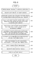
- the ordinary light observation is performed in the ordinary light mode. That is, the 445LD 34 is turned on, and the ordinary light image processing is performed on the captured image data using the white light in the ordinary light image processing unit 64.
- the special light mode is switched by a user.
- a mode switching signal special light ON
- the image processing in the image processing switching section 60 is switched to the special light mode (S10).
- the light amount of the light source is adjusted (S20). There is a need to perform an adjustment of the light emission amount from the light source in accordance with a variation in positional relation between the front end of the endoscope and the subject.
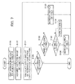
- the adjustment of the light amount of the light source when fixing the position between the front end the endoscope and the subject is performed according to the steps shown in Fig. 7 .
- narrow band light (405 nm) is emitted from the blue-violet laser beam (405LD) 32, and narrow band light (405 nm) and excitation and emission light thereof are emitted as illumination light from the front end of the endoscope toward the subject (S120).
- the emitted illumination light is reflected by the subject, and the returned light is acquired as captured image information by the imaging element 26 (S122).
- the captured image information is acquired, the captured image information is output to the light amount calculating unit 50 through the CDS and AGC circuit 44 and the A/D converter 46, and the light amount (the luminance value of the captured image) of the returned light at the imaging element 26 is calculated (S124).
- the calculated light amount of the returned light is output to the light source control section 48.
- the light source control section 48 determines whether the light amount is sufficient on the basis of the light amount calculated at the light amount calculating unit 56, that is, the light amount of the returned light is a predetermined value or more (S126). When the light amount is sufficient, the irradiation light amount at that position does not need to be performed, and the subject is captured as shown in Fig. 6 without adjusting the light amount of the light source (S30). Of course, when the light amount is too much, so that an overflow occurs in the imaging element 26, a control is performed so that the current value of the driving current flowing to the 405LD 32 is decreased.
- the light source control section 48 determines whether the output of the 405LD 32 is maximal from the current value of the driving current flowing to the 405LD 32 (S128).
- the light source control section 48 increases the output (the current value of the driving current) of the 405LD 32 (S130), and calculates the light amount again (S124).
- the light source control section 48 determines whether the blue laser beam source (445LD) 34 is turned on (S132). When the 445LD 34 is not turned on, the 445LD 34 is turned on (S134), and the light amount is calculated again (S124). When the 445LD 34 is turned on, the narrow band light (405 nm) and the excitation and emission light thereof as illumination light overlap each other, and the narrow band light (445 nm) and the excitation and emission light thereof are emitted from the front end of the endoscope to the subject.
- the light emission amount is adjusted on the basis of the steps shown in Fig. 7 until the light amount of the returned light at the imaging element 26 becomes a predetermined value or more. Furthermore, although it is not described in the steps of Fig. 7 , when the light amount is not sufficient even after maximally increasing the output of the 445LD 34, the subject is directly captured as shown in Fig. 6 (S30) or the position between the front end of the endoscope and the subject is adjusted again so as to move the front end of the endoscope close to the subject.
- the light emission amount from the light source may be fixed, and the position between the front end of the endoscope and the subject may be changed.
- two operations may be supposed.
- One is a case in which the light emission amount of the 405LD 32 is set to a predetermined value, the 445LD 34 is stopped, and the positional relation between the front end of the endoscope and the subject is changed.
- the other is a case in which the light emission amount of the 405LD 32 is set to be maximal, the light emission amount of the 445LD 34 is set to a predetermined value, and the positional relation between the front end of the endoscope and the subject is changed.
- the case of only using the 405LD 32 is mainly used for a case where a capturing operation is performed by moving the front end of the endoscope and the subject close to each other.
- the case of setting the light emission amount of the 405LD 32 to be maximal and setting the light emission amount of the 445LD 34 to a predetermined value is mainly used for a case where a capturing operation is performed by moving the front end of the endoscope and the subject far from each other.
- the subject is captured, and the captured image information is acquired by the imaging element 26 (S30).
- the captured image information is appropriately processed by the CDS and AGC circuit 44 and the A/D converter 36, and is output to the light amount calculating unit 56.
- the light amount calculating unit 56 the light amount of B light and the light amount of G light are respectively calculated from the captured image information, and are ouput to the light amount ratio calculating section 56 (S32). Further, the captured image information is output as a captured image signal to the special light image processing unit 64 through the DSP 52 and the noise removing circuit 54.
- the light emission amount of the 405LD 32 and the light emission amount of the 445LD 32 of the light source control section 48 are acquired, and the light amount ratio between the 405LD 32 and the 445LD 34 is calculated (S34).
- the calculated light amount ratio is output to the special light color converting section 74 of the special light image processing unit 64.
- the special light color converting section 74 of the special light image processing unit 64 On the basis of the information of the light amount ratio, in the special light color converting section 74 of the special light image processing unit 64, the color conversion coefficients k R , k G , and k B used for the special light color conversion are set from the calculated light amount ratio information and the color conversion coefficient table 80, and the captured image signal input to the special light image processing unit 64 becomes predetermined RGB image data by the special light color converting section 74 (S36). Furthermore, an image emphasizing process such as a frame summing process may be performed before the special light color conversion.
- the output image display signal is displayed as a special light image on the monitor 38, and is recorded in the recording device 42 (S40).
Landscapes
- Health & Medical Sciences (AREA)
- Life Sciences & Earth Sciences (AREA)
- Surgery (AREA)
- Engineering & Computer Science (AREA)
- Biomedical Technology (AREA)
- Molecular Biology (AREA)
- Pathology (AREA)
- Radiology & Medical Imaging (AREA)
- Nuclear Medicine, Radiotherapy & Molecular Imaging (AREA)
- Biophysics (AREA)
- Physics & Mathematics (AREA)
- Heart & Thoracic Surgery (AREA)
- Medical Informatics (AREA)
- Optics & Photonics (AREA)
- Animal Behavior & Ethology (AREA)
- General Health & Medical Sciences (AREA)
- Public Health (AREA)
- Veterinary Medicine (AREA)
- Signal Processing (AREA)
- Multimedia (AREA)
- Endoscopes (AREA)
- Closed-Circuit Television Systems (AREA)
Applications Claiming Priority (1)
| Application Number | Priority Date | Filing Date | Title |
|---|---|---|---|
| JP2010219437A JP5371921B2 (ja) | 2010-09-29 | 2010-09-29 | 内視鏡装置 |
Publications (2)
| Publication Number | Publication Date |
|---|---|
| EP2436303A2 true EP2436303A2 (fr) | 2012-04-04 |
| EP2436303A3 EP2436303A3 (fr) | 2017-06-21 |
Family
ID=44720708
Family Applications (1)
| Application Number | Title | Priority Date | Filing Date |
|---|---|---|---|
| EP11183044.4A Withdrawn EP2436303A3 (fr) | 2010-09-29 | 2011-09-28 | Dispositif d'endoscope |
Country Status (4)
| Country | Link |
|---|---|
| US (1) | US9179074B2 (fr) |
| EP (1) | EP2436303A3 (fr) |
| JP (1) | JP5371921B2 (fr) |
| CN (1) | CN102429624B (fr) |
Cited By (1)
| Publication number | Priority date | Publication date | Assignee | Title |
|---|---|---|---|---|
| EP3087900A4 (fr) * | 2013-12-25 | 2017-11-15 | Olympus Corporation | Dispositif d'observation du type à balayage optique |
Families Citing this family (18)
| Publication number | Priority date | Publication date | Assignee | Title |
|---|---|---|---|---|
| JP6101048B2 (ja) * | 2012-02-20 | 2017-03-22 | キヤノン株式会社 | 画像処理装置及び画像処理方法 |
| JP5677378B2 (ja) * | 2012-07-25 | 2015-02-25 | 富士フイルム株式会社 | 内視鏡システム |
| JP2014171511A (ja) * | 2013-03-06 | 2014-09-22 | Olympus Corp | 被検体観察システム及びその方法 |
| JP5931031B2 (ja) * | 2013-09-23 | 2016-06-08 | 富士フイルム株式会社 | 内視鏡システム及び内視鏡システムの作動方法 |
| US9372292B2 (en) * | 2013-12-13 | 2016-06-21 | Canon Kabushiki Kaisha | Imaging apparatus having light source identification and image quality correction functions and method for controlling imaging apparatus |
| CA2940120C (fr) * | 2014-02-20 | 2019-05-14 | Integrated Medical Systems International, Inc. | Systeme d'eclairage pour endoscope et procede de creation d'ombre et perception amelioree de la profondeur et de detection amelioree des contours |
| JP6353288B2 (ja) * | 2014-06-19 | 2018-07-04 | オリンパス株式会社 | 光走査型内視鏡装置 |
| CN107105996B (zh) * | 2015-01-30 | 2018-11-20 | 奥林巴斯株式会社 | 照明装置、内窥镜系统及色调修正装置 |
| JP6840737B2 (ja) * | 2016-04-21 | 2021-03-10 | 富士フイルム株式会社 | 内視鏡システム、プロセッサ装置、及び、内視鏡システムの作動方法 |
| CN110248584B (zh) * | 2017-02-01 | 2022-02-18 | 富士胶片株式会社 | 内窥镜系统及其工作方法 |
| JP6891076B2 (ja) * | 2017-08-31 | 2021-06-18 | 富士フイルム株式会社 | プロセッサ装置とその作動方法、および内視鏡システム |
| JP6947918B2 (ja) * | 2018-04-05 | 2021-10-13 | オリンパス株式会社 | 内視鏡用光源装置及びその発光光量制御方法 |
| JP6615950B2 (ja) * | 2018-07-05 | 2019-12-04 | 富士フイルム株式会社 | 内視鏡システム、プロセッサ装置、内視鏡システムの作動方法、及びプロセッサ装置の作動方法 |
| JP7239360B2 (ja) * | 2019-03-19 | 2023-03-14 | ソニー・オリンパスメディカルソリューションズ株式会社 | 光源装置、医療用観察システム、照明方法およびプログラム |
| JP2022012599A (ja) * | 2020-07-02 | 2022-01-17 | ソニーグループ株式会社 | 医療システム、情報処理装置及び情報処理方法 |
| JP7637491B2 (ja) * | 2020-10-27 | 2025-02-28 | Hoya株式会社 | 内視鏡システム |
| TWI854569B (zh) * | 2023-03-31 | 2024-09-01 | 宸祿科技股份有限公司 | 內視鏡裝置、內視鏡醫療輔助系統及內視鏡影像處理方法 |
| WO2026062455A1 (fr) * | 2024-09-18 | 2026-03-26 | Alcon Inc. | Commande de moteurs de lumière pour éclairage |
Citations (2)
| Publication number | Priority date | Publication date | Assignee | Title |
|---|---|---|---|---|
| JP3559755B2 (ja) | 2000-07-27 | 2004-09-02 | オリンパス株式会社 | 内視鏡装置 |
| JP3607857B2 (ja) | 2000-07-27 | 2005-01-05 | オリンパス株式会社 | 内視鏡装置 |
Family Cites Families (28)
| Publication number | Priority date | Publication date | Assignee | Title |
|---|---|---|---|---|
| US5001556A (en) * | 1987-09-30 | 1991-03-19 | Olympus Optical Co., Ltd. | Endoscope apparatus for processing a picture image of an object based on a selected wavelength range |
| US7179222B2 (en) * | 1996-11-20 | 2007-02-20 | Olympus Corporation | Fluorescent endoscope system enabling simultaneous achievement of normal light observation based on reflected light and fluorescence observation based on light with wavelengths in infrared spectrum |
| US7892169B2 (en) | 2000-07-21 | 2011-02-22 | Olympus Corporation | Endoscope apparatus |
| JP4321697B2 (ja) * | 2000-08-02 | 2009-08-26 | 富士フイルム株式会社 | 蛍光画像表示方法および装置 |
| DE60228165D1 (de) * | 2001-05-16 | 2008-09-25 | Olympus Corp | Endoskop mit Bildverarbeitungseinrichtung |
| JP2003000537A (ja) * | 2001-06-27 | 2003-01-07 | Fuji Photo Film Co Ltd | 内視鏡用の撮像方法および装置 |
| JP2003135393A (ja) * | 2001-10-30 | 2003-05-13 | Olympus Optical Co Ltd | 内視鏡システムの自動調整方法 |
| JP3965174B2 (ja) * | 2004-09-02 | 2007-08-29 | オリンパス株式会社 | 内視鏡装置 |
| JP2006122335A (ja) * | 2004-10-28 | 2006-05-18 | Morita Mfg Co Ltd | カメラ装置 |
| JP4424292B2 (ja) * | 2005-09-28 | 2010-03-03 | ソニー株式会社 | 撮像装置、露出制御方法およびプログラム |
| JP4727374B2 (ja) * | 2005-09-30 | 2011-07-20 | 富士フイルム株式会社 | 電子内視鏡装置 |
| JP4767649B2 (ja) * | 2005-10-14 | 2011-09-07 | 富士フイルム株式会社 | 内視鏡装置 |
| JP4391998B2 (ja) * | 2006-03-07 | 2009-12-24 | オリンパス株式会社 | 内視鏡装置 |
| JP4891990B2 (ja) * | 2006-04-12 | 2012-03-07 | オリンパスメディカルシステムズ株式会社 | 内視鏡装置 |
| JP4728162B2 (ja) * | 2006-04-21 | 2011-07-20 | オリンパスメディカルシステムズ株式会社 | 内視鏡システム |
| JP4868976B2 (ja) * | 2006-08-18 | 2012-02-01 | オリンパスメディカルシステムズ株式会社 | 内視鏡装置 |
| JP4895834B2 (ja) * | 2007-01-23 | 2012-03-14 | Hoya株式会社 | 画像処理装置 |
| JP5133595B2 (ja) * | 2007-05-15 | 2013-01-30 | オリンパスメディカルシステムズ株式会社 | 照明光検出用光学系並びにそれを備えた光学装置及び内視鏡装置 |
| JP2009034224A (ja) * | 2007-07-31 | 2009-02-19 | Olympus Medical Systems Corp | 医療装置 |
| JP5184016B2 (ja) * | 2007-09-12 | 2013-04-17 | オンセミコンダクター・トレーディング・リミテッド | 撮像装置 |
| JP4954858B2 (ja) * | 2007-11-30 | 2012-06-20 | オリンパス株式会社 | 蛍光観察装置および内視鏡装置 |
| JP2009142415A (ja) * | 2007-12-13 | 2009-07-02 | Fujinon Corp | 内視鏡システム |
| JP5138444B2 (ja) * | 2008-03-31 | 2013-02-06 | 富士フイルム株式会社 | 内視鏡 |
| JP5081720B2 (ja) | 2008-05-22 | 2012-11-28 | 富士フイルム株式会社 | 蛍光内視鏡装置および励起光ユニット |
| US20090289200A1 (en) * | 2008-05-22 | 2009-11-26 | Fujifilm Corporation | Fluorescent image obtainment method and apparatus, fluorescence endoscope, and excitation-light unit |
| JP2010063484A (ja) * | 2008-09-08 | 2010-03-25 | Fujinon Corp | 補助具及びそれを用いる内視鏡システム |
| JP2010119593A (ja) * | 2008-11-19 | 2010-06-03 | Hoya Corp | 内視鏡システム |
| JP2011200367A (ja) * | 2010-03-25 | 2011-10-13 | Fujifilm Corp | 画像撮像方法および装置 |
-
2010
- 2010-09-29 JP JP2010219437A patent/JP5371921B2/ja active Active
-
2011
- 2011-09-22 US US13/239,562 patent/US9179074B2/en active Active
- 2011-09-28 EP EP11183044.4A patent/EP2436303A3/fr not_active Withdrawn
- 2011-09-29 CN CN201110303479.2A patent/CN102429624B/zh active Active
Patent Citations (2)
| Publication number | Priority date | Publication date | Assignee | Title |
|---|---|---|---|---|
| JP3559755B2 (ja) | 2000-07-27 | 2004-09-02 | オリンパス株式会社 | 内視鏡装置 |
| JP3607857B2 (ja) | 2000-07-27 | 2005-01-05 | オリンパス株式会社 | 内視鏡装置 |
Cited By (2)
| Publication number | Priority date | Publication date | Assignee | Title |
|---|---|---|---|---|
| EP3087900A4 (fr) * | 2013-12-25 | 2017-11-15 | Olympus Corporation | Dispositif d'observation du type à balayage optique |
| US10151914B2 (en) | 2013-12-25 | 2018-12-11 | Olympus Corporation | Optical scanning observation apparatus |
Also Published As
| Publication number | Publication date |
|---|---|
| CN102429624B (zh) | 2015-09-02 |
| JP5371921B2 (ja) | 2013-12-18 |
| US9179074B2 (en) | 2015-11-03 |
| CN102429624A (zh) | 2012-05-02 |
| EP2436303A3 (fr) | 2017-06-21 |
| JP2012071020A (ja) | 2012-04-12 |
| US20120075449A1 (en) | 2012-03-29 |
Similar Documents
| Publication | Publication Date | Title |
|---|---|---|
| US9179074B2 (en) | Endoscope device | |
| EP2436304B1 (fr) | Dispositif d'endoscope | |
| US9072453B2 (en) | Endoscope apparatus | |
| US8970685B2 (en) | Endoscope apparatus | |
| US20150366444A1 (en) | Endoscope system, light source device, operation method for endoscope system, and operation method for light source device | |
| US20190087970A1 (en) | Endoscope system, processor device, and endoscope system operation method | |
| EP3251581B1 (fr) | Dispositif de processeur pour endoscope, son procédé de fonctionnement, et programme de commande | |
| US20140340497A1 (en) | Processor device, endoscope system, and operation method of endoscope system | |
| US10003774B2 (en) | Image processing device and method for operating endoscope system | |
| US9595117B2 (en) | Image processing device and method for operating endoscope system | |
| US20190246874A1 (en) | Processor device, endoscope system, and method of operating processor device | |
| US20160295085A1 (en) | Endoscope system, processing apparatus and endoscope operating method | |
| JP6550420B2 (ja) | 内視鏡装置 | |
| JP2012050641A (ja) | 内視鏡システム | |
| JP5538143B2 (ja) | 内視鏡システム | |
| JP2016158837A (ja) | 内視鏡光源装置、内視鏡システム、及び内視鏡光源装置の作動方法 | |
| JP6039605B2 (ja) | 内視鏡システム及びその作動方法 | |
| JP6378140B2 (ja) | 内視鏡システム及びその作動方法 | |
| JP6386939B2 (ja) | 内視鏡光源装置、内視鏡システム、及び内視鏡光源装置の作動方法 | |
| JP5897673B2 (ja) | 内視鏡システム及びその駆動方法 | |
| JP2016209517A (ja) | 内視鏡システム及びその作動方法 | |
| JP2014193371A (ja) | 内視鏡システム |
Legal Events
| Date | Code | Title | Description |
|---|---|---|---|
| PUAI | Public reference made under article 153(3) epc to a published international application that has entered the european phase |
Free format text: ORIGINAL CODE: 0009012 |
|
| AK | Designated contracting states |
Kind code of ref document: A2 Designated state(s): AL AT BE BG CH CY CZ DE DK EE ES FI FR GB GR HR HU IE IS IT LI LT LU LV MC MK MT NL NO PL PT RO RS SE SI SK SM TR |
|
| AX | Request for extension of the european patent |
Extension state: BA ME |
|
| PUAL | Search report despatched |
Free format text: ORIGINAL CODE: 0009013 |
|
| AK | Designated contracting states |
Kind code of ref document: A3 Designated state(s): AL AT BE BG CH CY CZ DE DK EE ES FI FR GB GR HR HU IE IS IT LI LT LU LV MC MK MT NL NO PL PT RO RS SE SI SK SM TR |
|
| AX | Request for extension of the european patent |
Extension state: BA ME |
|
| RIC1 | Information provided on ipc code assigned before grant |
Ipc: H04N 5/225 20060101ALI20170517BHEP Ipc: A61B 1/045 20060101ALI20170517BHEP Ipc: A61B 1/06 20060101AFI20170517BHEP Ipc: H04N 5/235 20060101ALI20170517BHEP Ipc: A61B 1/00 20060101ALI20170517BHEP Ipc: A61B 1/04 20060101ALI20170517BHEP |
|
| STAA | Information on the status of an ep patent application or granted ep patent |
Free format text: STATUS: REQUEST FOR EXAMINATION WAS MADE |
|
| 17P | Request for examination filed |
Effective date: 20171219 |
|
| RBV | Designated contracting states (corrected) |
Designated state(s): AL AT BE BG CH CY CZ DE DK EE ES FI FR GB GR HR HU IE IS IT LI LT LU LV MC MK MT NL NO PL PT RO RS SE SI SK SM TR |
|
| STAA | Information on the status of an ep patent application or granted ep patent |
Free format text: STATUS: EXAMINATION IS IN PROGRESS |
|
| 17Q | First examination report despatched |
Effective date: 20201119 |
|
| RAP3 | Party data changed (applicant data changed or rights of an application transferred) |
Owner name: FUJIFILM CORPORATION |
|
| REG | Reference to a national code |
Ref country code: DE Ref legal event code: R079 Free format text: PREVIOUS MAIN CLASS: A61B0001060000 Ipc: H04N0023100000 |
|
| GRAP | Despatch of communication of intention to grant a patent |
Free format text: ORIGINAL CODE: EPIDOSNIGR1 |
|
| STAA | Information on the status of an ep patent application or granted ep patent |
Free format text: STATUS: GRANT OF PATENT IS INTENDED |
|
| RIC1 | Information provided on ipc code assigned before grant |
Ipc: A61B 1/045 20060101ALI20240328BHEP Ipc: A61B 1/04 20060101ALI20240328BHEP Ipc: A61B 1/00 20060101ALI20240328BHEP Ipc: A61B 1/06 20060101ALI20240328BHEP Ipc: H04N 23/76 20230101ALI20240328BHEP Ipc: H04N 23/74 20230101ALI20240328BHEP Ipc: H04N 23/72 20230101ALI20240328BHEP Ipc: H04N 23/71 20230101ALI20240328BHEP Ipc: H04N 23/667 20230101ALI20240328BHEP Ipc: H04N 23/10 20230101AFI20240328BHEP Ipc: H04N 23/50 20230101ALI20240328BHEP |
|
| INTG | Intention to grant announced |
Effective date: 20240426 |
|
| STAA | Information on the status of an ep patent application or granted ep patent |
Free format text: STATUS: THE APPLICATION IS DEEMED TO BE WITHDRAWN |
|
| 18D | Application deemed to be withdrawn |
Effective date: 20240827 |