EP2436331A1 - Dispositif électromédical destiné à la réduction ou la suppression non invasive de tissus adipeux sous-cutanés - Google Patents
Dispositif électromédical destiné à la réduction ou la suppression non invasive de tissus adipeux sous-cutanés Download PDFInfo
- Publication number
- EP2436331A1 EP2436331A1 EP11182538A EP11182538A EP2436331A1 EP 2436331 A1 EP2436331 A1 EP 2436331A1 EP 11182538 A EP11182538 A EP 11182538A EP 11182538 A EP11182538 A EP 11182538A EP 2436331 A1 EP2436331 A1 EP 2436331A1
- Authority
- EP
- European Patent Office
- Prior art keywords
- individual radiators
- individual
- radiators
- dipole
- electromagnetic waves
- Prior art date
- Legal status (The legal status is an assumption and is not a legal conclusion. Google has not performed a legal analysis and makes no representation as to the accuracy of the status listed.)
- Withdrawn
Links
- 210000004003 subcutaneous fat Anatomy 0.000 title claims abstract description 10
- 206010033675 panniculitis Diseases 0.000 title claims description 8
- 230000009467 reduction Effects 0.000 title claims description 5
- 230000005672 electromagnetic field Effects 0.000 claims description 20
- 230000008859 change Effects 0.000 claims description 13
- 210000000577 adipose tissue Anatomy 0.000 claims description 10
- 239000011159 matrix material Substances 0.000 claims description 4
- 238000007920 subcutaneous administration Methods 0.000 claims description 3
- 210000001519 tissue Anatomy 0.000 abstract description 8
- 230000005855 radiation Effects 0.000 description 19
- 238000010586 diagram Methods 0.000 description 9
- 238000011161 development Methods 0.000 description 4
- 230000018109 developmental process Effects 0.000 description 4
- 238000000034 method Methods 0.000 description 4
- 210000001789 adipocyte Anatomy 0.000 description 3
- 238000007493 shaping process Methods 0.000 description 3
- 230000006978 adaptation Effects 0.000 description 2
- 210000002615 epidermis Anatomy 0.000 description 2
- 238000007443 liposuction Methods 0.000 description 2
- 210000003205 muscle Anatomy 0.000 description 2
- 238000010521 absorption reaction Methods 0.000 description 1
- 238000007792 addition Methods 0.000 description 1
- 230000004075 alteration Effects 0.000 description 1
- 230000002457 bidirectional effect Effects 0.000 description 1
- 230000037237 body shape Effects 0.000 description 1
- 230000030833 cell death Effects 0.000 description 1
- 238000010276 construction Methods 0.000 description 1
- 238000002316 cosmetic surgery Methods 0.000 description 1
- 230000001419 dependent effect Effects 0.000 description 1
- 239000003814 drug Substances 0.000 description 1
- 229940079593 drug Drugs 0.000 description 1
- 230000000694 effects Effects 0.000 description 1
- 230000005684 electric field Effects 0.000 description 1
- 230000035876 healing Effects 0.000 description 1
- 238000004519 manufacturing process Methods 0.000 description 1
- 230000002503 metabolic effect Effects 0.000 description 1
- 230000004060 metabolic process Effects 0.000 description 1
- 230000000149 penetrating effect Effects 0.000 description 1
- 230000035515 penetration Effects 0.000 description 1
- 230000008569 process Effects 0.000 description 1
- 210000003491 skin Anatomy 0.000 description 1
- 238000002560 therapeutic procedure Methods 0.000 description 1
- 238000010792 warming Methods 0.000 description 1
Images

Classifications
-
- A—HUMAN NECESSITIES
- A61—MEDICAL OR VETERINARY SCIENCE; HYGIENE
- A61B—DIAGNOSIS; SURGERY; IDENTIFICATION
- A61B18/00—Surgical instruments, devices or methods for transferring non-mechanical forms of energy to or from the body
- A61B18/18—Surgical instruments, devices or methods for transferring non-mechanical forms of energy to or from the body by applying electromagnetic radiation, e.g. microwaves
- A61B18/1815—Surgical instruments, devices or methods for transferring non-mechanical forms of energy to or from the body by applying electromagnetic radiation, e.g. microwaves using microwaves
-
- A—HUMAN NECESSITIES
- A61—MEDICAL OR VETERINARY SCIENCE; HYGIENE
- A61N—ELECTROTHERAPY; MAGNETOTHERAPY; RADIATION THERAPY; ULTRASOUND THERAPY
- A61N1/00—Electrotherapy; Circuits therefor
- A61N1/02—Details
- A61N1/04—Electrodes
- A61N1/06—Electrodes for high-frequency therapy
-
- A—HUMAN NECESSITIES
- A61—MEDICAL OR VETERINARY SCIENCE; HYGIENE
- A61N—ELECTROTHERAPY; MAGNETOTHERAPY; RADIATION THERAPY; ULTRASOUND THERAPY
- A61N1/00—Electrotherapy; Circuits therefor
- A61N1/18—Applying electric currents by contact electrodes
- A61N1/32—Applying electric currents by contact electrodes alternating or intermittent currents
-
- A—HUMAN NECESSITIES
- A61—MEDICAL OR VETERINARY SCIENCE; HYGIENE
- A61N—ELECTROTHERAPY; MAGNETOTHERAPY; RADIATION THERAPY; ULTRASOUND THERAPY
- A61N1/00—Electrotherapy; Circuits therefor
- A61N1/40—Applying electric fields by inductive or capacitive coupling ; Applying radio-frequency signals
- A61N1/403—Applying electric fields by inductive or capacitive coupling ; Applying radio-frequency signals for thermotherapy, e.g. hyperthermia
-
- A—HUMAN NECESSITIES
- A61—MEDICAL OR VETERINARY SCIENCE; HYGIENE
- A61N—ELECTROTHERAPY; MAGNETOTHERAPY; RADIATION THERAPY; ULTRASOUND THERAPY
- A61N2/00—Magnetotherapy
- A61N2/02—Magnetotherapy using magnetic fields produced by coils, including single turn loops or electromagnets
-
- A—HUMAN NECESSITIES
- A61—MEDICAL OR VETERINARY SCIENCE; HYGIENE
- A61B—DIAGNOSIS; SURGERY; IDENTIFICATION
- A61B18/00—Surgical instruments, devices or methods for transferring non-mechanical forms of energy to or from the body
- A61B18/18—Surgical instruments, devices or methods for transferring non-mechanical forms of energy to or from the body by applying electromagnetic radiation, e.g. microwaves
-
- A—HUMAN NECESSITIES
- A61—MEDICAL OR VETERINARY SCIENCE; HYGIENE
- A61B—DIAGNOSIS; SURGERY; IDENTIFICATION
- A61B18/00—Surgical instruments, devices or methods for transferring non-mechanical forms of energy to or from the body
- A61B2018/00053—Mechanical features of the instrument of device
- A61B2018/0016—Energy applicators arranged in a two- or three dimensional array
-
- A—HUMAN NECESSITIES
- A61—MEDICAL OR VETERINARY SCIENCE; HYGIENE
- A61B—DIAGNOSIS; SURGERY; IDENTIFICATION
- A61B18/00—Surgical instruments, devices or methods for transferring non-mechanical forms of energy to or from the body
- A61B2018/00315—Surgical instruments, devices or methods for transferring non-mechanical forms of energy to or from the body for treatment of particular body parts
- A61B2018/00452—Skin
- A61B2018/00458—Deeper parts of the skin, e.g. treatment of vascular disorders or port wine stains
- A61B2018/00464—Subcutaneous fat, e.g. liposuction, lipolysis
-
- A—HUMAN NECESSITIES
- A61—MEDICAL OR VETERINARY SCIENCE; HYGIENE
- A61B—DIAGNOSIS; SURGERY; IDENTIFICATION
- A61B18/00—Surgical instruments, devices or methods for transferring non-mechanical forms of energy to or from the body
- A61B18/04—Surgical instruments, devices or methods for transferring non-mechanical forms of energy to or from the body by heating
- A61B18/12—Surgical instruments, devices or methods for transferring non-mechanical forms of energy to or from the body by heating by passing a current through the tissue to be heated, e.g. high-frequency current
- A61B18/1206—Generators therefor
- A61B2018/1246—Generators therefor characterised by the output polarity
- A61B2018/126—Generators therefor characterised by the output polarity bipolar
-
- A—HUMAN NECESSITIES
- A61—MEDICAL OR VETERINARY SCIENCE; HYGIENE
- A61B—DIAGNOSIS; SURGERY; IDENTIFICATION
- A61B18/00—Surgical instruments, devices or methods for transferring non-mechanical forms of energy to or from the body
- A61B18/18—Surgical instruments, devices or methods for transferring non-mechanical forms of energy to or from the body by applying electromagnetic radiation, e.g. microwaves
- A61B18/1815—Surgical instruments, devices or methods for transferring non-mechanical forms of energy to or from the body by applying electromagnetic radiation, e.g. microwaves using microwaves
- A61B2018/183—Surgical instruments, devices or methods for transferring non-mechanical forms of energy to or from the body by applying electromagnetic radiation, e.g. microwaves using microwaves characterised by the type of antenna
- A61B2018/1838—Dipole antennas
Definitions
- the invention relates to an electromedical device for non-invasively reducing or removing subcutaneous adipose tissue.
- the US 5,143,063 describes a method of removing fatty tissue by focusing microwaves on the fatty tissue to be removed.
- a focusing device in the form of a parabolic mirror is used there.
- the use of parabolic mirrors as a single radiator requires a very material- and cost-intensive production path for the electromedical device, in particular if the device is to have a plurality of individual radiators.
- the focussing and focusing ability of the described apparatus through the use of parabolic mirrors as a focusing device has limits that do not meet the requirements as they are desired in a medical application.
- the publication US 5,507,790 describes a method for non-invasive removal of adipose tissue.
- microwave lenses are used for focusing.
- drugs with a metabolic effect are also used which are supposed to generate an increased fat metabolism. In this case, a reduction in the volume of fat cells is achieved without causing cell death of the fat cells.
- the complex microwave optics used has microwave lenses, which are known to have a low quality and high aberrations. These properties hinder an advantageous focusing of the microwave radiation used in the sense of an effective treatment, since a limitation of the irradiation power to the desired treatment area is difficult to realize.
- the object underlying the present invention is to easily remove or reduce excess subcutaneous adipose tissue non-invasively.
- the idea underlying the invention is to easily control the individual individual radiators of the electromedical device according to the invention such that the best possible adaptation of the electromagnetic total field to the body shapes of the persons to be treated can take place. Elaborate mechanical adjustment operations of the electromedical device are advantageously dispensable.
- Controlled and targeted local tissue warming results in the desired reduction or removal of subcutaneous adipose tissue.
- the electromedical device has essentially single-radiators arranged in matrix form and / or in cascade.
- a cascade-shaped arrangement of the individual radiators In a cascade-shaped arrangement of the individual radiators, a series connection or a consecutive linking of the individual radiators is provided.
- the individual radiators In a matrix-shaped arrangement of the individual radiators, the individual radiators arrayically, ie in Columns and rows arranged and interconnected.
- the generation of a multiplicity of differently designed field geometries is preferably possible in a simple manner. Furthermore, a prompt and appropriate change between these field geometries by a simple and adapted control of the individual radiator of the electromedical device is possible.
- At least one of the individual radiators is designed as a dipole antenna. Due to the design of the individual radiator as a dipole, a desired emission geometry of the individual radiator can be effected.
- At least one of the dipole antennas is formed as a ⁇ / 2-dipole or ⁇ -dipole.
- At least one of the individual radiators is designed as a spot radiator.
- the respective individual radiators are aligned such that the individual radiators generate the electromagnetic waves generated by them each in the same direction.
- the individual radiator emits the emitted electromagnetic field in the direction of the body of a person to be treated.
- the same direction is thus awarded by how and in what way the person is applied by the device according to the invention, that is applied to the person.
- the direction of this application of the device thus determines the predetermined direction.
- control device is designed to change the frequencies and / or the amplitude and / or the power of the emitted electromagnetic waves of a single radiator.
- the electromagnetic field is varied by the device according to the invention.
- the electromagnetic field is changed in particular with regard to its intensity and extent and its homogeneity.
- This change can be changed in a simple manner via a variation of the frequency, the amplitude and / or the power of the emitted electromagnetic waves of the individual radiator. In this way, depending on the depth at which the subcutaneous fatty tissue is present in the body of a person to be treated, as well as the density and consistency of this fatty tissue, the electromagnetic field can be exactly adjusted.
- control devices on at least one delay element.
- a respective delay element is adapted to the electromagnetic field generated by a single radiator by a Changing a respective signal propagation time of the control signal to change. By varying and suitably adapting the signal propagation times of the various individual emitters, the total electromagnetic field can be adjusted as required.
- a control element has at least one phase shifter.
- a respective phase shifter is set up to change the respective electromagnetic field of the individual radiators by changing its respective phase. This measure also makes it possible to effect a change in the geometry of the electromagnetic total field as required.
- the device is designed in the frequency range between 0.4-61.5 GHz, preferably between 1.0-7.5 GHz, and particularly preferably between 1.6-5.9 GHz, and in particular to work between 2.4-2.5 GHz.
- a radiation can be used which achieves the best possible absorption behavior of the radiation in the area to be treated.
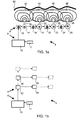
- Fig. 1a shows a schematic representation of the structure of an embodiment of an electromedical device 5 for non-invasive reducing or removing subcutaneous adipose tissue, according to a first embodiment of the present invention.
- the electromedical device 5 comprises a base part 6, which comprises a directional control 10 and a power source 11. Furthermore, the electromedical device 5 comprises an extension part 8 which is assembled with variable composition of its construction, for example cascade-shaped or matrix-shaped, of further subassemblies.
- the directivity controller 10 is electrically connected on the one hand to the energy source 11 and on the other hand, for example, with a first control member 12.
- the first control member 12 is further coupled via a first control device 14 to a first individual radiator 32.
- a second control member 16 is connected to the first control device 14, which in turn is coupled to a second control device 18.
- the second control device 18 has, in addition to this connection, firstly a connection to a second individual emitter 34 and secondly to a third control element 20.
- the third control element 20 is further connected to a third control device 22 and the third control device 22 is furthermore provided with a third individual emitter 36 and coupled to a fourth control member 24.
- the fourth control member 24 is then in turn connected to a fourth control device 26.
- the fourth control device 26 is connected to a fourth individual radiator 38.
- Fig. 1 By way of example, four individual emitters with corresponding control devices and control elements are shown - but it goes without saying that any other multiplicity of individual emitters is also possible.
- the power source 11 supplies the electromedical device 5 with energy via the directivity controller 10.
- the directivity controller 10 also injects a high frequency signal into the first controller 12.
- the first controller 12 then feeds a high-frequency signal into the first controller 14, in which the high-frequency signal is shared.
- a first part of the high-frequency signal is provided for emission via the first individual radiator 32.
- a second part of the high-frequency signal is fed by the first control device 14 via the second control member 16 in the second control device 18, in which in turn a division into a provided for the radiation via the second individual radiator 34 and part for forwarding to the third control member 20th provided part takes place.
- the third control element 20 feeds the high-frequency signal further into the third control device 22.
- the third control device feeds a signal for emission into the third individual emitter 36 and also forwards a signal to the fourth control element 24.
- the fourth control member 24 supplies the fourth control device 26, which feeds the fourth individual radiator 38 for radiation.
- each individual radiator 32, 34, 36, 38 individually supplied with a controllable, and in particular in the phase and frequency variable, high-frequency signal.
- This cascading of control elements and control devices in conjunction with the directivity control 10 allows the inventive design of a desired field geometry of the total electromagnetic field 50, which by superimposing of the respective individual radiators 32, 34, 36, 38 emitted electromagnetic fields 42, 44, 46, 48 is created.
- the individual emitters 32, 34, 36, 38 can each be designed as a dipole antenna, in particular as a ⁇ / 2 dipole antenna, as a ⁇ -dipole antenna or as a 3 ⁇ / 2 dipole antenna.
- a dipole antenna in particular as a ⁇ / 2 dipole antenna, as a ⁇ -dipole antenna or as a 3 ⁇ / 2 dipole antenna.
- the radiation characteristics of such exemplary antenna shapes for the single radiators will be discussed below with respect to FIGS Fig. 2 to 4 explained in more detail.
- the first control element 12 may include, for example, a delay element and / or a phase shifter, wherein the delay element is determined for the change in transit time of the input high-frequency signal and the phase shifter is designed for phase change of the injected high-frequency signal.
- the delay element is determined for the change in transit time of the input high-frequency signal and the phase shifter is designed for phase change of the injected high-frequency signal.
- Fig. 1b shows a schematic representation of an electromedical device according to another embodiment of the invention.
- the electromedical device 5 includes here as well as in Fig. 1a an energy source 11 and a directivity controller 10, which may be arranged in a base part 6.
- the electromedical device 5 comprises individual radiators 32, 34, 36, 38, which are coupled to the directional control 10 and are powered by the power source 11 with energy.
- Fig. 1a an energy source 11 and a directivity controller 10 which may be arranged in a base part 6.
- the electromedical device 5 comprises individual radiators 32, 34, 36, 38, which are coupled to the directional control 10 and are powered by the power source 11 with energy.
- the individual radiators 32 and 34 and the individual radiators 36 and 38 are each cascade-coupled in a horizontal arrangement one behind the other.
- the cascades of the individual radiators 32 and 34 and the individual radiators 36 and 38 are arranged vertically one above the other in a matrix.
- the present arrangement of the single emitters 32, 34, 36 and 38 is only exemplary in nature. Of course, other cascade and matrix arrangement, for example, with offset rows of cascades or cascade rows having a different number of individual radiators possible.
- Fig. 1b therefore, for purposes of illustration, further individual radiators are indicated by dashed lines, which can be provided in addition to the individual radiators 32, 34, 36 and 38.
- the number of individual beams is in Fig. 1b given as four, however, any number of individual radiators from a number of two may be used equally.
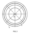
- Fig. 2 shows a schematic diagram of the radiation characteristic of a ⁇ / 2-dipole in a polar diagram, according to a first embodiment of the present invention.
- the radiation characteristic of a ⁇ / 2 dipole applied in a polar coordinate system 80 has a spherical characteristic 70 and depends on the dimensions of the single radiator in relation to the wavelength of the radiated radiation and their shaping can be adjusted by changing the frequency. In the case of the ⁇ / 2 dipole 60a, there is no directivity of the radiation characteristic.
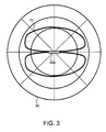
- Fig. 3 shows a schematic diagram of the radiation characteristic of a ⁇ -dipole in a polar diagram, according to a first embodiment of the present invention.
- the radiation characteristic of a ⁇ -dipole shown in a polar coordinate system 80 has a figure-of-eight characteristic 72 and depends on the dimensions of the individual radiator in relation to the wavelength of the radiated radiation and its shaping can be adjusted by changing the frequency.
- a directivity of the emission characteristic is given with emission maxima perpendicular to the dipole axis.
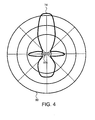
- Fig. 4 shows a schematic diagram of the radiation characteristic of a 3 ⁇ / 2-dipole in a polar diagram, according to a first embodiment of the present invention.
- the emission characteristic of a 3 ⁇ / 2-dipole applied in a polar coordinate system 80 has a lobe characteristic 74 and depends on the design of the single radiator in relation to the wavelength of the emitted radiation and its shaping can be adjusted via a change of the frequency.
- the 3 ⁇ / 2-dipole 60c is a directivity of the radiation characteristic with emission maxima orthogonal and parallel to the dipole axis.
- Fig. 5 shows a schematic representation of a human tissue region and its spatial position to the total electromagnetic field 50, which is generated by three dipole antennas of the electromedical device according to the invention, according to a first embodiment of the present invention.
- a first dipole antenna 94a, a second dipole antenna 94b and a third dipole antenna 94c generate an adapted overall electromagnetic field 50 by superimposing their respective different emission characteristics 96a, 96b, 96c.
- the second dipole antenna 94b is operated as a ⁇ -dipole
- the first dipole antenna 94a and the third dipole antenna 94c are switched as a 3 ⁇ / 2-dipole.
- the field geometry achieved by the adaptation according to the invention can advantageously be predetermined by the outline of the human tissue region 95 to be treated. It goes without saying that, depending on the tissue region, 95 different field geometries are possible by means of different combinations of individual radiators designed for different antennas.
- the performance of the dipole antennas 94a, 94b, 94c is adapted to a desired penetration depth of the total electromagnetic field 50 in the fatty tissue 90 further.
- the total electromagnetic field 50 penetrates through the epidermis 92 without penetrating too deeply into the muscle tissue 91.
Landscapes
- Health & Medical Sciences (AREA)
- Life Sciences & Earth Sciences (AREA)
- Engineering & Computer Science (AREA)
- Biomedical Technology (AREA)
- Nuclear Medicine, Radiotherapy & Molecular Imaging (AREA)
- Animal Behavior & Ethology (AREA)
- General Health & Medical Sciences (AREA)
- Public Health (AREA)
- Veterinary Medicine (AREA)
- Radiology & Medical Imaging (AREA)
- Surgery (AREA)
- Physics & Mathematics (AREA)
- Otolaryngology (AREA)
- Electromagnetism (AREA)
- Heart & Thoracic Surgery (AREA)
- Medical Informatics (AREA)
- Molecular Biology (AREA)
- Radiation-Therapy Devices (AREA)
- Surgical Instruments (AREA)
- Electrotherapy Devices (AREA)
Applications Claiming Priority (1)
| Application Number | Priority Date | Filing Date | Title |
|---|---|---|---|
| DE102010041649A DE102010041649A1 (de) | 2010-09-29 | 2010-09-29 | Elektromedizinische Vorrichtung zum nicht-invasiven Reduzieren oder Entfernen von subkutanem Fettgewebe |
Publications (1)
| Publication Number | Publication Date |
|---|---|
| EP2436331A1 true EP2436331A1 (fr) | 2012-04-04 |
Family
ID=44719462
Family Applications (1)
| Application Number | Title | Priority Date | Filing Date |
|---|---|---|---|
| EP11182538A Withdrawn EP2436331A1 (fr) | 2010-09-29 | 2011-09-23 | Dispositif électromédical destiné à la réduction ou la suppression non invasive de tissus adipeux sous-cutanés |
Country Status (6)
| Country | Link |
|---|---|
| US (1) | US8744594B2 (fr) |
| EP (1) | EP2436331A1 (fr) |
| JP (2) | JP2012071134A (fr) |
| KR (1) | KR101302814B1 (fr) |
| DE (1) | DE102010041649A1 (fr) |
| IL (1) | IL215406A0 (fr) |
Cited By (1)
| Publication number | Priority date | Publication date | Assignee | Title |
|---|---|---|---|---|
| USD1028258S1 (en) | 2019-11-20 | 2024-05-21 | Zeltiq Aesthetics, Inc. | Applicator for a therapeutic device |
Families Citing this family (2)
| Publication number | Priority date | Publication date | Assignee | Title |
|---|---|---|---|---|
| JP6331550B2 (ja) | 2014-03-25 | 2018-05-30 | 株式会社デンソー | 統合装置 |
| FR3099705B1 (fr) * | 2019-08-05 | 2024-10-04 | Biopass | Dispositif pour l’émission d’un champ magnétique |
Citations (4)
| Publication number | Priority date | Publication date | Assignee | Title |
|---|---|---|---|---|
| US5143063A (en) | 1988-02-09 | 1992-09-01 | Fellner Donald G | Method of removing adipose tissue from the body |
| US5507790A (en) | 1994-03-21 | 1996-04-16 | Weiss; William V. | Method of non-invasive reduction of human site-specific subcutaneous fat tissue deposits by accelerated lipolysis metabolism |
| US20090221999A1 (en) * | 2008-02-29 | 2009-09-03 | Ramin Shahidi | Thermal Ablation Design and Planning Methods |
| US20100217253A1 (en) * | 2007-06-15 | 2010-08-26 | Primaeva Medical, Inc. | Devices and methods for percutaneous energy delivery |
Family Cites Families (8)
| Publication number | Priority date | Publication date | Assignee | Title |
|---|---|---|---|---|
| JPH01115370A (ja) * | 1987-10-28 | 1989-05-08 | Fumiaki Okada | 加温療法用アプリケータ |
| WO2000053113A1 (fr) * | 1999-03-09 | 2000-09-14 | Thermage, Inc. | Appareil et procede destines au traitement de tissus |
| US6463336B1 (en) * | 1999-04-01 | 2002-10-08 | Mmtc, Inc | Active bandage suitable for applying pulsed radio-frequencies or microwaves to the skin for medical purposes |
| US20060265034A1 (en) * | 2005-04-05 | 2006-11-23 | Ams Medical Sa | Microwave devices for treating biological samples and tissue and methods for using same |
| WO2007141874A1 (fr) * | 2006-06-09 | 2007-12-13 | Medical Appliance Co., Ltd. | dispositif de traitement de la douleur exquise à haute fréquence |
| US8700176B2 (en) * | 2006-07-27 | 2014-04-15 | Pollogen Ltd. | Apparatus and method for non-invasive treatment of skin tissue |
| GB0624584D0 (en) * | 2006-12-08 | 2007-01-17 | Medical Device Innovations Ltd | Skin treatment apparatus and method |
| AU2008335715B2 (en) | 2007-12-12 | 2014-01-23 | Miradry, Inc. | Systems, apparatus, methods and procedures for the noninvasive treatment of tissue using microwave energy |
-
2010
- 2010-09-29 DE DE102010041649A patent/DE102010041649A1/de not_active Withdrawn
-
2011
- 2011-09-23 EP EP11182538A patent/EP2436331A1/fr not_active Withdrawn
- 2011-09-27 JP JP2011211093A patent/JP2012071134A/ja active Pending
- 2011-09-27 IL IL215406A patent/IL215406A0/en unknown
- 2011-09-29 KR KR1020110099060A patent/KR101302814B1/ko not_active Expired - Fee Related
- 2011-09-29 US US13/248,163 patent/US8744594B2/en not_active Expired - Fee Related
-
2013
- 2013-12-24 JP JP2013266137A patent/JP2014061443A/ja not_active Withdrawn
Patent Citations (4)
| Publication number | Priority date | Publication date | Assignee | Title |
|---|---|---|---|---|
| US5143063A (en) | 1988-02-09 | 1992-09-01 | Fellner Donald G | Method of removing adipose tissue from the body |
| US5507790A (en) | 1994-03-21 | 1996-04-16 | Weiss; William V. | Method of non-invasive reduction of human site-specific subcutaneous fat tissue deposits by accelerated lipolysis metabolism |
| US20100217253A1 (en) * | 2007-06-15 | 2010-08-26 | Primaeva Medical, Inc. | Devices and methods for percutaneous energy delivery |
| US20090221999A1 (en) * | 2008-02-29 | 2009-09-03 | Ramin Shahidi | Thermal Ablation Design and Planning Methods |
Cited By (1)
| Publication number | Priority date | Publication date | Assignee | Title |
|---|---|---|---|---|
| USD1028258S1 (en) | 2019-11-20 | 2024-05-21 | Zeltiq Aesthetics, Inc. | Applicator for a therapeutic device |
Also Published As
| Publication number | Publication date |
|---|---|
| US20120078326A1 (en) | 2012-03-29 |
| US8744594B2 (en) | 2014-06-03 |
| JP2012071134A (ja) | 2012-04-12 |
| DE102010041649A1 (de) | 2012-03-29 |
| KR20120033287A (ko) | 2012-04-06 |
| KR101302814B1 (ko) | 2013-09-02 |
| JP2014061443A (ja) | 2014-04-10 |
| IL215406A0 (en) | 2012-04-30 |
Similar Documents
| Publication | Publication Date | Title |
|---|---|---|
| DE10310765A1 (de) | Sonde und Vorrichtung für eine Thermotherapie | |
| DE69405583T2 (de) | Minimalinvasive monopole phasengesteuerte strahler für hyperthermie zur behandlung von brustkarzinomen | |
| EP2022534B1 (fr) | Dispositif de commande destiné à commander un processus de rayonnement, installation de thérapie à particules ainsi que procédé de rayonnement d'un volume cible | |
| DE60123790T2 (de) | Asymetrisches übertragungssystem für radioelektrische therapie | |
| DE102018004568B4 (de) | Strahlungsquelle für Mikrowellen-Pulse und Strahlungseinrichtung | |
| DE69227688T2 (de) | Verwendung von piezoelektrischem kompositwandler für ultrasonische therapievorrichtung | |
| DE102008010958A1 (de) | Konformales Mehrschicht-Strahlentherapiesystem und dieses verwendende Teilchenstrahl-Therapievorrichtung | |
| EP2016979B1 (fr) | Dispositif d'application par rayon de particules, dispositif de rayonnement et procédé de guidage d'un rayon de particules | |
| DE60206881T2 (de) | Ultraschallwandler und verfahren zur herstellung eines ultraschallwandlers | |
| DE112018005767T5 (de) | Vorrichtung zur Behandlung von Tumoren mittels evaneszenten Wellen | |
| DE102018211931A1 (de) | Vorrichtung zur Modenverwirbelung | |
| DE69927383T2 (de) | Verfahren zur kosmetischen behandlung der haut und der kopfhaut mit elektromagnetischen wellen und etherischen ölen | |
| EP2436331A1 (fr) | Dispositif électromédical destiné à la réduction ou la suppression non invasive de tissus adipeux sous-cutanés | |
| EP3685425B1 (fr) | Dispositif pour traiter un produit au moyen de micro-ondes | |
| EP3161903B1 (fr) | Antenne avec un lobe ajustable et méthode pour opérer celle-ci | |
| EP3031439B1 (fr) | Systeme de generation d'ondes a ultrasons | |
| DE3930930C1 (fr) | ||
| EP2539903A1 (fr) | Dispositif et procédé d'exposition à un rayonnement pour le dépôt d'une dose dans un volume cible | |
| DE8226546U1 (de) | Einrichtung zur beaufschlagung des gewebes eines patienten mit einem hochfrequenten elektromagnetischen feld zur foerderung des heilens | |
| DE102017121731A1 (de) | Vorrichtung zur Behandlung eines Produkts mit Mikrowellen | |
| DE112010002639B4 (de) | Antenneneinrichtung | |
| EP3996206A1 (fr) | Antenne cornet et sa reconstruction | |
| EP3513457A1 (fr) | Dispositif d'antenne et procédé de rayonnement d'ondes électromagnétiques avec le dispositif d'antenne | |
| EP4154292B1 (fr) | Dispositif de traitement par micro-ondes | |
| DE69417639T2 (de) | Therapiegerät mit variabler fokussierung ohne sekundärfokussierung |
Legal Events
| Date | Code | Title | Description |
|---|---|---|---|
| PUAI | Public reference made under article 153(3) epc to a published international application that has entered the european phase |
Free format text: ORIGINAL CODE: 0009012 |
|
| AK | Designated contracting states |
Kind code of ref document: A1 Designated state(s): AL AT BE BG CH CY CZ DE DK EE ES FI FR GB GR HR HU IE IS IT LI LT LU LV MC MK MT NL NO PL PT RO RS SE SI SK SM TR |
|
| AX | Request for extension of the european patent |
Extension state: BA ME |
|
| 17P | Request for examination filed |
Effective date: 20120329 |
|
| 17Q | First examination report despatched |
Effective date: 20120704 |
|
| GRAP | Despatch of communication of intention to grant a patent |
Free format text: ORIGINAL CODE: EPIDOSNIGR1 |
|
| INTG | Intention to grant announced |
Effective date: 20140411 |
|
| STAA | Information on the status of an ep patent application or granted ep patent |
Free format text: STATUS: THE APPLICATION IS DEEMED TO BE WITHDRAWN |
|
| 18D | Application deemed to be withdrawn |
Effective date: 20140822 |