EP2436456B1 - Rondelle d'écartement pour transmission et son procédé de fabrication - Google Patents
Rondelle d'écartement pour transmission et son procédé de fabrication Download PDFInfo
- Publication number
- EP2436456B1 EP2436456B1 EP11182669.9A EP11182669A EP2436456B1 EP 2436456 B1 EP2436456 B1 EP 2436456B1 EP 11182669 A EP11182669 A EP 11182669A EP 2436456 B1 EP2436456 B1 EP 2436456B1
- Authority
- EP
- European Patent Office
- Prior art keywords
- spacer
- spacer washer
- predetermined thickness
- recess
- thickness
- Prior art date
- Legal status (The legal status is an assumption and is not a legal conclusion. Google has not performed a legal analysis and makes no representation as to the accuracy of the status listed.)
- Not-in-force
Links
Images

Classifications
-
- B—PERFORMING OPERATIONS; TRANSPORTING
- B21—MECHANICAL METAL-WORKING WITHOUT ESSENTIALLY REMOVING MATERIAL; PUNCHING METAL
- B21K—MAKING FORGED OR PRESSED METAL PRODUCTS, e.g. HORSE-SHOES, RIVETS, BOLTS OR WHEELS
- B21K23/00—Making other articles
-
- B—PERFORMING OPERATIONS; TRANSPORTING
- B21—MECHANICAL METAL-WORKING WITHOUT ESSENTIALLY REMOVING MATERIAL; PUNCHING METAL
- B21K—MAKING FORGED OR PRESSED METAL PRODUCTS, e.g. HORSE-SHOES, RIVETS, BOLTS OR WHEELS
- B21K1/00—Making machine elements
- B21K1/76—Making machine elements elements not mentioned in one of the preceding groups
- B21K1/761—Making machine elements elements not mentioned in one of the preceding groups rings
-
- F—MECHANICAL ENGINEERING; LIGHTING; HEATING; WEAPONS; BLASTING
- F16—ENGINEERING ELEMENTS AND UNITS; GENERAL MEASURES FOR PRODUCING AND MAINTAINING EFFECTIVE FUNCTIONING OF MACHINES OR INSTALLATIONS; THERMAL INSULATION IN GENERAL
- F16B—DEVICES FOR FASTENING OR SECURING CONSTRUCTIONAL ELEMENTS OR MACHINE PARTS TOGETHER, e.g. NAILS, BOLTS, CIRCLIPS, CLAMPS, CLIPS OR WEDGES; JOINTS OR JOINTING
- F16B43/00—Washers or equivalent devices; Other devices for supporting bolt-heads or nuts
Definitions
- the present invention relates to a method of manufacturing a gear spacer having a predetermined thickness, comprising the steps of providing a green sheet and then machining to make the spacer so that the spacer obtains the predetermined thickness.
- the present invention relates to such a transmission spacer and a transmission with a shaft to which such a spacer is arranged.
- Spacer plates, start-up shims and shims are generally produced for use in transmissions made of metallic materials.
- the spacers must be made for use in such transmissions with tight tolerances.
- a transmission spacer according to the preamble of claim 7 is also from the document DE 199 02 565 A1 known.
- the spacer engages around the outer periphery of a planetary pin and is aligned centrally to the central axis of the bolt.
- the thrust washer is arranged axially on a planetary gear.
- the disc has an axial abutment surface which has a lubrication groove.
- the planetary gear will be through at least a bearing rotatably mounted on the bolt. At least a first contact zone of the disc has lubrication pockets.
- a method of manufacturing a gear spacer of a predetermined thickness comprising the steps of providing a green sheet and then machining to make the spacer so that the spacer obtains the predetermined thickness, the green sheet having a thickness less than has the predetermined thickness, wherein at least one side of the raw disc at least one axial recess is pressed, which protrudes from the other side as a survey, such that the distance between the one side of the spacer and the survey on the other side of the spacer at least the corresponds to predetermined thickness, and wherein the raw disc is subjected to the pressing of the at least one axial recess an axial pressing operation, so that the distance between the one side of the spacer and the survey on the other side of the spacer exactly entspric the predetermined thickness ht.
- a gear spacer with at least one axial recess formed on one side and projecting from the other side of the spacer as a survey, wherein a predetermined thickness of the spacer by the distance between the one side of the spacer and the elevation is formed on the other side of the spacer.
- the green sheet from a sheet having a relatively large thickness tolerance.
- the required thickness tolerance for the spacer can be provided in a cost effective manner.
- the configuration of the recesses and the adjustment of the height of the survey on the other side can be done by selecting a suitable die of a forming tool.
- the processing of the punched raw disc to achieve the predetermined thickness can generally be done in one operation.
- the predetermined thickness of the spacer can be adjusted or calibrated in this way.
- the green sheet is preferably made of a metal material such as steel and is preferably uncured.
- the process of indenting the depressions can be simultaneously established to achieve the predetermined thickness.
- the resulting thickness after depression of the recesses is preferably greater than the predetermined thickness.
- the predetermined thickness or calibration is then subsequently by the pressing process achieved. In this case, the impressions and pressing can be done in a forming tool.
- the stability of the spacer can be increased.
- a spacer can be made with a predetermined thickness, which is uniform over the circumference of the spacer.
- At least one depression is arranged at a distance from an inner periphery and / or from an outer periphery of the spacer.
- the forming tool can be easily constructed.
- an improved flow of lubricant can be realized.
- the spacer may preferably be formed as a stepped disc, wherein the recess is formed as an annular recess adjacent to a diameter (outer or inner).
- At least one recess extends in the radial direction from an inner circumference to an outer circumference of the spacer.
- the green sheet is provided by being punched out of a sheet.
- the sheet may in this case preferably be a standard sheet, which is manufactured with relatively large thickness tolerances.
- the recesses may be concentric with the spacer, eccentric thereto, and / or may be radial.
- the shaping can preferably be such that a lubricant supply or a lubricant flow can be optimized.
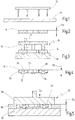
- Fig. 1 to 4 is shown in schematic form a method of manufacturing a gear spacer. It shows Fig. 1 the provision of a metal sheet 10 such as steel and a punching tool 12, by means of which a green sheet 14 from the sheet 10 is punched out.
- a metal sheet 10 such as steel
- a punching tool 12 by means of which a green sheet 14 from the sheet 10 is punched out.
- Fig. 2 shows a raw disc 14 produced in this way in cross section.
- the raw disk 14 is preferably circular, with a concentric Through-hole, for example for receiving a shaft.
- the green sheet 14 has a thickness D R , which may be subject to relatively large tolerances.
- Fig. 3 shows a first step of forming the green sheet 14 in a first forming tool 16.
- the first forming tool 16 has a punch 18 and a die 20 on which the green sheet 14 is arranged. At 21, an optional hold-down 21 is also shown.
- the forming tool 16 serves to depress on one side of the raw disc 14 axial depressions, which project from the other side as a survey. For this purpose, in the die 20 unspecified depressions may be formed.
- Fig. 4 shows a thus formed raw disc 14 having an inner periphery 24 and an outer periphery 26.
- a plurality of depressions 28 are pressed into a first side 30.
- On the second side 34 corresponding elevations 32 result at these locations.
- the total thickness of the converted raw disc 14 is in Fig. 4 drawn at D z .
- the total thickness Dz z is determined by a distance between the first side 30 of the raw disc 14 and the top of the elevations 32.
- the thickness D z is greater than the thickness D R of the punched raw disc 14 of Fig.
- the thickness D z is at least as large and preferably greater than the predetermined thickness to which the green sheet is to be reshaped (calibrated) in a subsequent step. Furthermore, the thickness D z is still subject to the large tolerances of the standard sheet 10 at this stage.
- Fig. 5 shows another forming tool 36 in the form of a press.
- the forming tool has a flat die 37 and a flat punch 38, between which the formed raw disc 14 is arranged.
- the further forming tool 36 serves to achieve the predetermined thickness Ds (for calibration).
- the further forming tool 36 may be integrated with the first forming tool 16, so that a re-clamping is not required.
- the predetermined thickness D s is independent of the large tolerances of the standard sheet 10.
- a calibration block 39 may be provided, which sets the predetermined thickness D s ; this can also be integrated with the die 37 or the stamp 38.
- Fig. 6 shows a schematic section of a transmission 40 for a motor vehicle.
- the transmission 40 has a shaft 42 with a first shaft portion 44.
- the first shaft portion 44 has at its periphery a bearing 46 (for example, a needle bearing).
- the shaft 42 further includes a second shaft portion 48 adjoining the first shaft portion 44.
- the second shaft portion 48 has a second bearing 49 at its periphery.
- a first idler gear 50 is attached on the bearing 46 of the first shaft portion 44.
- a second idler gear 52 is attached on the bearing 49 of the second shaft portion 48.
- Fig. 7 shows inen schematic section of another transmission 40.
- an alternative spacer 22 between a loose wheel 50 and a ball bearing is arranged.
- the spacer 22 is formed as a stepped disc, the elevation abuts an inner ring 56 of the ball bearing, so that at least between the outer ring 58 and the second side 34 of the spacer 22, a gap is established.
- the spacer 22 of the Fig. 5 is in Fig. 8 shown in a plan view. It can be seen that the spacer 22 has four recesses 28 distributed over the circumference.
- the recesses 28 are circular and spaced from both the inner periphery 24 and the outer periphery 26 of the spacer 22.
- the recesses 28 may also be elongated. Such elongated recesses may, for example, be radially aligned, as shown at 28 '. Further, the elongate recesses may also be circumferentially aligned, as shown at 28 ".
- Fig. 9 shows an alternative embodiment of a spacer 22.
- the spacer 22 has a single recess 28 ''', which is formed concentrically to the spacer 22 as an annular recess.
- FIG. 10 Another alternative embodiment of a spacer according to the invention is in Fig. 10 shown.
- the spacer 22 of the Fig. 10 has a plurality of radially extending recesses 28 IV extending from the inner periphery 24 to the outer periphery 26.
- the recesses 28 IV can be formed conically diverging in plan view, as it is in Fig. 10 is shown.
- Fig. 11 shows a stepped spacer 22 V , as used for example in the transmission of Fig. 7 is used.
- the annular recess 28 V is in this case arranged in the region of the inner circumference 24 of the spacer 22 V.
- spacers 22 are shown in which one or more depressions 28 are pressed from one side 30 into the spacer 22, so that on the opposite side 34 elevations 32 arise, it is alternatively also possible such depressions 28 from both sides, so that the total thickness of the spacer 22 is given by the distance between the projections 32 on the opposite sides.
- the first Side 30 of the spacer 22 thus be formed without or with elevations 32. In the latter case, the elevations 32 form the first side 30.
Landscapes
- Engineering & Computer Science (AREA)
- Mechanical Engineering (AREA)
- General Details Of Gearings (AREA)
- Gears, Cams (AREA)
- Powder Metallurgy (AREA)
Claims (9)
- Procédé de fabrication d'une rondelle d'écartement pour transmission (22) comprenant une épaisseur prédéterminée (DS), comprenant les étapes consistant à fournir une rondelle brute (14) et suite à la fabrication de la rondelle d'écartement (22), à l'usiner afin que la rondelle d'écartement (22) acquière l'épaisseur prédéterminée (DS),
la rondelle brute (14) présentant une plus faible épaisseur (DR) que l'épaisseur prédéterminée (DS), au moins un renfoncement axial (28) étant imprimé au moins depuis un côté (30) dans la rondelle brute (14), lequel fait saillie par rapport à l'autre côté (34) sous forme de rehaussement (32) de telle sorte que la distance (DZ) entre l'un des côtés (30) de la rondelle d'écartement (22) et le rehaussement (32) de l'autre côté (34) de la rondelle d'écartement (22) corresponde au moins à l'épaisseur prédéterminée (DS), et
la rondelle brute (14), après l'impression de l'au moins un renfoncement axial (28), étant soumise à une opération de pressage axial afin que la distance entre l'un des côtés (30) de la rondelle d'écartement (22) et le rehaussement (32) de l'autre côté (34) de la rondelle d'écartement (22) corresponde exactement à l'épaisseur prédéterminée (DS). - Procédé selon la revendication 1, dans lequel, dans l'étape d'usinage, une pluralité de renfoncements (28) sont imprimés.
- Procédé selon la revendication 2, dans lequel les renfoncements (28' ; 28" ; 28IV) sont répartis sur la périphérie de la rondelle d'écartement (22).
- Procédé selon l'une quelconque des revendications 1 à 3, dans lequel au moins un renfoncement (28' ; 28" ; 28''') est disposé à distance d'une périphérie intérieure (24) et/ou d'une périphérie extérieure (26) de la rondelle d'écartement (22).
- Procédé selon l'une quelconque des revendications 1 à 4, dans lequel au moins un renfoncement (28IV) s'étend dans la direction radiale depuis une périphérie intérieure (24) jusqu'à une périphérie extérieure (26) de la rondelle d'écartement (22).
- Procédé selon l'une quelconque des revendications 1 à 5, dans lequel la rondelle brute (14) est préparée par estampage à partir d'une tôle (10).
- Rondelle d'écartement pour transmission (22) comprenant au moins un renfoncement axial (28) qui est réalisé d'un côté (30), caractérisée en ce que l'au moins un renfoncement axial (28) fait saillie par rapport à l'autre côté (34) sous forme de rehaussement (32), une épaisseur prédéterminée (DS) de la rondelle d'écartement (22) étant formée par la distance entre l'un des côtés (30) de la rondelle d'écartement (22) et le rehaussement (32) de l'autre côté (34) de la rondelle d'écartement (22), la rondelle d'écartement (22) étant fabriquée par un procédé selon l'une quelconque des revendications 1 à 6.
- Transmission (40) comprenant un arbre (42) sur lequel est disposée une rondelle d'écartement (22) selon la revendication 7.
- Utilisation d'une rondelle d'écartement (22) selon la revendication 7 dans une transmission de véhicule automobile.
Applications Claiming Priority (1)
| Application Number | Priority Date | Filing Date | Title |
|---|---|---|---|
| DE102010047848A DE102010047848A1 (de) | 2010-09-29 | 2010-09-29 | Getriebe-Distanzscheibe und Verfahren zu deren Herstellung |
Publications (3)
| Publication Number | Publication Date |
|---|---|
| EP2436456A2 EP2436456A2 (fr) | 2012-04-04 |
| EP2436456A3 EP2436456A3 (fr) | 2015-04-08 |
| EP2436456B1 true EP2436456B1 (fr) | 2017-08-23 |
Family
ID=44677736
Family Applications (1)
| Application Number | Title | Priority Date | Filing Date |
|---|---|---|---|
| EP11182669.9A Not-in-force EP2436456B1 (fr) | 2010-09-29 | 2011-09-26 | Rondelle d'écartement pour transmission et son procédé de fabrication |
Country Status (2)
| Country | Link |
|---|---|
| EP (1) | EP2436456B1 (fr) |
| DE (1) | DE102010047848A1 (fr) |
Cited By (2)
| Publication number | Priority date | Publication date | Assignee | Title |
|---|---|---|---|---|
| DE102021125543A1 (de) | 2021-10-01 | 2023-04-06 | Dt Swiss Ag | Laufradkomponente für ein Laufrad eines wenigstens teilweise mit Muskelkraft betriebenen Zweirads und Laufrad |
| WO2026017710A1 (fr) * | 2024-07-18 | 2026-01-22 | Heico Befestigungstechnik Gmbh | Rondelle de blocage |
Families Citing this family (2)
| Publication number | Priority date | Publication date | Assignee | Title |
|---|---|---|---|---|
| JP6432239B2 (ja) * | 2014-09-19 | 2018-12-05 | アイシン精機株式会社 | 車両の後輪操舵装置 |
| DE102015211301A1 (de) * | 2015-06-19 | 2016-12-22 | Schaeffler Technologies AG & Co. KG | Verfahren zur Herstellung einer Abstimmscheibe und Werkzeug zur Herstellung einer Abstimmscheibe sowie Abstimmscheibe |
Citations (3)
| Publication number | Priority date | Publication date | Assignee | Title |
|---|---|---|---|---|
| DE4440085A1 (de) * | 1994-11-10 | 1996-05-15 | Evertz Karl Heinz | Umformverfahren |
| WO2000075521A1 (fr) * | 1999-06-08 | 2000-12-14 | Ks Gleitlager Gmbh | Element de palier de butee |
| DE10203265A1 (de) * | 2002-01-29 | 2003-07-31 | Ina Schaeffler Kg | Anlaufscheibe eines Planetengetriebes |
Family Cites Families (6)
| Publication number | Priority date | Publication date | Assignee | Title |
|---|---|---|---|---|
| DE4032602C1 (en) * | 1990-10-15 | 1991-07-25 | A. Friedr. Flender Ag, 4290 Bocholt, De | Axial adjustment spacer for bearings - has oversize blank placed in press and upset between plates |
| US5794484A (en) * | 1993-11-23 | 1998-08-18 | Ford Global Technologies, Inc. | Universally making waved parts |
| DE19902565B4 (de) * | 1999-01-22 | 2009-06-04 | Schaeffler Kg | Anlaufscheibe eines Planetentriebes |
| US6789992B2 (en) * | 2002-09-20 | 2004-09-14 | Sunonwealth Electric Machine Industry Co., Ltd. | Washer having oil-bearing holes |
| DE10334880A1 (de) * | 2003-07-29 | 2005-03-03 | Ina-Schaeffler Kg | Anlaufscheibe für Planetengetriebe |
| DE102008054242A1 (de) | 2008-10-24 | 2010-01-21 | Ks Gleitlager Gmbh | Gleitlager |
-
2010
- 2010-09-29 DE DE102010047848A patent/DE102010047848A1/de not_active Ceased
-
2011
- 2011-09-26 EP EP11182669.9A patent/EP2436456B1/fr not_active Not-in-force
Patent Citations (3)
| Publication number | Priority date | Publication date | Assignee | Title |
|---|---|---|---|---|
| DE4440085A1 (de) * | 1994-11-10 | 1996-05-15 | Evertz Karl Heinz | Umformverfahren |
| WO2000075521A1 (fr) * | 1999-06-08 | 2000-12-14 | Ks Gleitlager Gmbh | Element de palier de butee |
| DE10203265A1 (de) * | 2002-01-29 | 2003-07-31 | Ina Schaeffler Kg | Anlaufscheibe eines Planetengetriebes |
Cited By (3)
| Publication number | Priority date | Publication date | Assignee | Title |
|---|---|---|---|---|
| DE102021125543A1 (de) | 2021-10-01 | 2023-04-06 | Dt Swiss Ag | Laufradkomponente für ein Laufrad eines wenigstens teilweise mit Muskelkraft betriebenen Zweirads und Laufrad |
| DE102021125543B4 (de) | 2021-10-01 | 2023-05-25 | Dt Swiss Ag | Laufradkomponente für ein Laufrad eines wenigstens teilweise mit Muskelkraft betriebenen Zweirads und Laufrad |
| WO2026017710A1 (fr) * | 2024-07-18 | 2026-01-22 | Heico Befestigungstechnik Gmbh | Rondelle de blocage |
Also Published As
| Publication number | Publication date |
|---|---|
| DE102010047848A1 (de) | 2012-03-29 |
| EP2436456A3 (fr) | 2015-04-08 |
| EP2436456A2 (fr) | 2012-04-04 |
Similar Documents
| Publication | Publication Date | Title |
|---|---|---|
| EP2210005B1 (fr) | Palier axial, en particulier pour un turbocompresseur | |
| DE102008006065B4 (de) | Verfahren zur Herstellung einer Tellerfeder | |
| DE2718970A1 (de) | Verfahren und vorrichtung zum herstellen von bremsscheiben fuer fahrzeuge | |
| EP3648911B1 (fr) | Procédé de fabrication d'une plaque de refroidissement | |
| EP2436456B1 (fr) | Rondelle d'écartement pour transmission et son procédé de fabrication | |
| EP2276941B1 (fr) | Procédé de fabrication d'un support de palier | |
| WO2009146679A1 (fr) | Procédé de fabrication d'un élément de cage pour une cage de roulement et cage de roulement | |
| DE102004031830A1 (de) | Verfahren zur Herstellung einer Lageranordnung | |
| WO2012084110A1 (fr) | Disque de frein et procédé de fabrication de ce disque | |
| DE102015115293A1 (de) | Vorrichtung zur Herstellung einer Nabeneinheit | |
| EP3906124B1 (fr) | Procédé de fabrication d'une plaque de refroidissement | |
| DE102011102288A1 (de) | Vorrichtung und Verfahren zur Herstellung eines Stirnrads mit einer Schrägverzahnung | |
| WO2007128359A1 (fr) | Procédé de fabrication d'un élément de transmission | |
| DE102014216346B4 (de) | Tellerfeder für eine Reibungskupplung und Verfahren zu deren Herstellung | |
| DE10061403B4 (de) | Verfahren zur Herstellung eines rotationssymmetrischen Formkörpers | |
| DE10211135B4 (de) | Verfahren und Vorrichtung zur Herstellung eines Formkörpers | |
| EP1632297B1 (fr) | Méthode et outillage de poinçonnage et/ou de formage | |
| DE10328199B4 (de) | Verfahren zur Herstellung eines Formteils zur direkten oder indirekten Aufnahme wenigstens eines Lagerrings, sowie Lageranordnung | |
| DE102014210631A1 (de) | Blechzylinder mit Mitnahmeprofil und Verfahren zur Herstellung | |
| DE102006031536B3 (de) | Lagerscheibe und Verfahren zu deren Herstellung | |
| DE102014209508A1 (de) | Verfahren zur Herstellung einer Druckplatte | |
| DE102013101695A1 (de) | Kupplungsscheibe und Herstellungsverfahren | |
| DE102022133507B4 (de) | Spindelmutter und Verfahren zur Herstellung einer Profilhülse für einen Kugelgewindetrieb | |
| DE10218520B4 (de) | Verfahren zur Herstellung einer Gewindedurchsetzung | |
| DE102013225382A1 (de) | Kupplungszwischendruckplatte |
Legal Events
| Date | Code | Title | Description |
|---|---|---|---|
| PUAI | Public reference made under article 153(3) epc to a published international application that has entered the european phase |
Free format text: ORIGINAL CODE: 0009012 |
|
| AK | Designated contracting states |
Kind code of ref document: A2 Designated state(s): AL AT BE BG CH CY CZ DE DK EE ES FI FR GB GR HR HU IE IS IT LI LT LU LV MC MK MT NL NO PL PT RO RS SE SI SK SM TR |
|
| AX | Request for extension of the european patent |
Extension state: BA ME |
|
| PUAL | Search report despatched |
Free format text: ORIGINAL CODE: 0009013 |
|
| AK | Designated contracting states |
Kind code of ref document: A3 Designated state(s): AL AT BE BG CH CY CZ DE DK EE ES FI FR GB GR HR HU IE IS IT LI LT LU LV MC MK MT NL NO PL PT RO RS SE SI SK SM TR |
|
| AX | Request for extension of the european patent |
Extension state: BA ME |
|
| RIC1 | Information provided on ipc code assigned before grant |
Ipc: B21K 23/00 20060101ALI20150227BHEP Ipc: B21K 1/76 20060101AFI20150227BHEP Ipc: F16B 43/00 20060101ALI20150227BHEP |
|
| 17P | Request for examination filed |
Effective date: 20150730 |
|
| RBV | Designated contracting states (corrected) |
Designated state(s): AL AT BE BG CH CY CZ DE DK EE ES FI FR GB GR HR HU IE IS IT LI LT LU LV MC MK MT NL NO PL PT RO RS SE SI SK SM TR |
|
| 17Q | First examination report despatched |
Effective date: 20160314 |
|
| GRAP | Despatch of communication of intention to grant a patent |
Free format text: ORIGINAL CODE: EPIDOSNIGR1 |
|
| RAP1 | Party data changed (applicant data changed or rights of an application transferred) |
Owner name: GETRAG B.V. & CO. KG |
|
| INTG | Intention to grant announced |
Effective date: 20170310 |
|
| GRAS | Grant fee paid |
Free format text: ORIGINAL CODE: EPIDOSNIGR3 |
|
| GRAA | (expected) grant |
Free format text: ORIGINAL CODE: 0009210 |
|
| AK | Designated contracting states |
Kind code of ref document: B1 Designated state(s): AL AT BE BG CH CY CZ DE DK EE ES FI FR GB GR HR HU IE IS IT LI LT LU LV MC MK MT NL NO PL PT RO RS SE SI SK SM TR |
|
| REG | Reference to a national code |
Ref country code: GB Ref legal event code: FG4D Free format text: NOT ENGLISH |
|
| REG | Reference to a national code |
Ref country code: CH Ref legal event code: EP |
|
| REG | Reference to a national code |
Ref country code: AT Ref legal event code: REF Ref document number: 920790 Country of ref document: AT Kind code of ref document: T Effective date: 20170915 |
|
| REG | Reference to a national code |
Ref country code: IE Ref legal event code: FG4D Free format text: LANGUAGE OF EP DOCUMENT: GERMAN |
|
| REG | Reference to a national code |
Ref country code: DE Ref legal event code: R096 Ref document number: 502011012842 Country of ref document: DE |
|
| REG | Reference to a national code |
Ref country code: FR Ref legal event code: PLFP Year of fee payment: 7 |
|
| REG | Reference to a national code |
Ref country code: NL Ref legal event code: MP Effective date: 20170823 |
|
| REG | Reference to a national code |
Ref country code: LT Ref legal event code: MG4D |
|
| PG25 | Lapsed in a contracting state [announced via postgrant information from national office to epo] |
Ref country code: NL Free format text: LAPSE BECAUSE OF FAILURE TO SUBMIT A TRANSLATION OF THE DESCRIPTION OR TO PAY THE FEE WITHIN THE PRESCRIBED TIME-LIMIT Effective date: 20170823 Ref country code: FI Free format text: LAPSE BECAUSE OF FAILURE TO SUBMIT A TRANSLATION OF THE DESCRIPTION OR TO PAY THE FEE WITHIN THE PRESCRIBED TIME-LIMIT Effective date: 20170823 Ref country code: NO Free format text: LAPSE BECAUSE OF FAILURE TO SUBMIT A TRANSLATION OF THE DESCRIPTION OR TO PAY THE FEE WITHIN THE PRESCRIBED TIME-LIMIT Effective date: 20171123 Ref country code: HR Free format text: LAPSE BECAUSE OF FAILURE TO SUBMIT A TRANSLATION OF THE DESCRIPTION OR TO PAY THE FEE WITHIN THE PRESCRIBED TIME-LIMIT Effective date: 20170823 Ref country code: SE Free format text: LAPSE BECAUSE OF FAILURE TO SUBMIT A TRANSLATION OF THE DESCRIPTION OR TO PAY THE FEE WITHIN THE PRESCRIBED TIME-LIMIT Effective date: 20170823 Ref country code: LT Free format text: LAPSE BECAUSE OF FAILURE TO SUBMIT A TRANSLATION OF THE DESCRIPTION OR TO PAY THE FEE WITHIN THE PRESCRIBED TIME-LIMIT Effective date: 20170823 |
|
| PG25 | Lapsed in a contracting state [announced via postgrant information from national office to epo] |
Ref country code: IS Free format text: LAPSE BECAUSE OF FAILURE TO SUBMIT A TRANSLATION OF THE DESCRIPTION OR TO PAY THE FEE WITHIN THE PRESCRIBED TIME-LIMIT Effective date: 20171223 Ref country code: GR Free format text: LAPSE BECAUSE OF FAILURE TO SUBMIT A TRANSLATION OF THE DESCRIPTION OR TO PAY THE FEE WITHIN THE PRESCRIBED TIME-LIMIT Effective date: 20171124 Ref country code: PL Free format text: LAPSE BECAUSE OF FAILURE TO SUBMIT A TRANSLATION OF THE DESCRIPTION OR TO PAY THE FEE WITHIN THE PRESCRIBED TIME-LIMIT Effective date: 20170823 Ref country code: BG Free format text: LAPSE BECAUSE OF FAILURE TO SUBMIT A TRANSLATION OF THE DESCRIPTION OR TO PAY THE FEE WITHIN THE PRESCRIBED TIME-LIMIT Effective date: 20171123 Ref country code: RS Free format text: LAPSE BECAUSE OF FAILURE TO SUBMIT A TRANSLATION OF THE DESCRIPTION OR TO PAY THE FEE WITHIN THE PRESCRIBED TIME-LIMIT Effective date: 20170823 Ref country code: ES Free format text: LAPSE BECAUSE OF FAILURE TO SUBMIT A TRANSLATION OF THE DESCRIPTION OR TO PAY THE FEE WITHIN THE PRESCRIBED TIME-LIMIT Effective date: 20170823 Ref country code: LV Free format text: LAPSE BECAUSE OF FAILURE TO SUBMIT A TRANSLATION OF THE DESCRIPTION OR TO PAY THE FEE WITHIN THE PRESCRIBED TIME-LIMIT Effective date: 20170823 |
|
| PG25 | Lapsed in a contracting state [announced via postgrant information from national office to epo] |
Ref country code: CZ Free format text: LAPSE BECAUSE OF FAILURE TO SUBMIT A TRANSLATION OF THE DESCRIPTION OR TO PAY THE FEE WITHIN THE PRESCRIBED TIME-LIMIT Effective date: 20170823 Ref country code: DK Free format text: LAPSE BECAUSE OF FAILURE TO SUBMIT A TRANSLATION OF THE DESCRIPTION OR TO PAY THE FEE WITHIN THE PRESCRIBED TIME-LIMIT Effective date: 20170823 Ref country code: RO Free format text: LAPSE BECAUSE OF FAILURE TO SUBMIT A TRANSLATION OF THE DESCRIPTION OR TO PAY THE FEE WITHIN THE PRESCRIBED TIME-LIMIT Effective date: 20170823 |
|
| REG | Reference to a national code |
Ref country code: CH Ref legal event code: PL |
|
| REG | Reference to a national code |
Ref country code: DE Ref legal event code: R097 Ref document number: 502011012842 Country of ref document: DE |
|
| PG25 | Lapsed in a contracting state [announced via postgrant information from national office to epo] |
Ref country code: SK Free format text: LAPSE BECAUSE OF FAILURE TO SUBMIT A TRANSLATION OF THE DESCRIPTION OR TO PAY THE FEE WITHIN THE PRESCRIBED TIME-LIMIT Effective date: 20170823 Ref country code: SM Free format text: LAPSE BECAUSE OF FAILURE TO SUBMIT A TRANSLATION OF THE DESCRIPTION OR TO PAY THE FEE WITHIN THE PRESCRIBED TIME-LIMIT Effective date: 20170823 Ref country code: EE Free format text: LAPSE BECAUSE OF FAILURE TO SUBMIT A TRANSLATION OF THE DESCRIPTION OR TO PAY THE FEE WITHIN THE PRESCRIBED TIME-LIMIT Effective date: 20170823 Ref country code: IT Free format text: LAPSE BECAUSE OF FAILURE TO SUBMIT A TRANSLATION OF THE DESCRIPTION OR TO PAY THE FEE WITHIN THE PRESCRIBED TIME-LIMIT Effective date: 20170823 Ref country code: MC Free format text: LAPSE BECAUSE OF FAILURE TO SUBMIT A TRANSLATION OF THE DESCRIPTION OR TO PAY THE FEE WITHIN THE PRESCRIBED TIME-LIMIT Effective date: 20170823 |
|
| REG | Reference to a national code |
Ref country code: DE Ref legal event code: R082 Ref document number: 502011012842 Country of ref document: DE Representative=s name: RAUSCH, GABRIELE, DIPL.-PHYS. DR.RER.NAT., DE |
|
| REG | Reference to a national code |
Ref country code: IE Ref legal event code: MM4A |
|
| REG | Reference to a national code |
Ref country code: BE Ref legal event code: MM Effective date: 20170930 |
|
| PG25 | Lapsed in a contracting state [announced via postgrant information from national office to epo] |
Ref country code: LU Free format text: LAPSE BECAUSE OF NON-PAYMENT OF DUE FEES Effective date: 20170926 |
|
| PLBE | No opposition filed within time limit |
Free format text: ORIGINAL CODE: 0009261 |
|
| STAA | Information on the status of an ep patent application or granted ep patent |
Free format text: STATUS: NO OPPOSITION FILED WITHIN TIME LIMIT |
|
| GBPC | Gb: european patent ceased through non-payment of renewal fee |
Effective date: 20171123 |
|
| PG25 | Lapsed in a contracting state [announced via postgrant information from national office to epo] |
Ref country code: IE Free format text: LAPSE BECAUSE OF NON-PAYMENT OF DUE FEES Effective date: 20170926 Ref country code: CH Free format text: LAPSE BECAUSE OF NON-PAYMENT OF DUE FEES Effective date: 20170930 Ref country code: LI Free format text: LAPSE BECAUSE OF NON-PAYMENT OF DUE FEES Effective date: 20170930 |
|
| 26N | No opposition filed |
Effective date: 20180524 |
|
| PG25 | Lapsed in a contracting state [announced via postgrant information from national office to epo] |
Ref country code: SI Free format text: LAPSE BECAUSE OF FAILURE TO SUBMIT A TRANSLATION OF THE DESCRIPTION OR TO PAY THE FEE WITHIN THE PRESCRIBED TIME-LIMIT Effective date: 20170823 Ref country code: BE Free format text: LAPSE BECAUSE OF NON-PAYMENT OF DUE FEES Effective date: 20170930 |
|
| REG | Reference to a national code |
Ref country code: FR Ref legal event code: PLFP Year of fee payment: 8 |
|
| PG25 | Lapsed in a contracting state [announced via postgrant information from national office to epo] |
Ref country code: MT Free format text: LAPSE BECAUSE OF FAILURE TO SUBMIT A TRANSLATION OF THE DESCRIPTION OR TO PAY THE FEE WITHIN THE PRESCRIBED TIME-LIMIT Effective date: 20170823 |
|
| REG | Reference to a national code |
Ref country code: AT Ref legal event code: MM01 Ref document number: 920790 Country of ref document: AT Kind code of ref document: T Effective date: 20170926 |
|
| PG25 | Lapsed in a contracting state [announced via postgrant information from national office to epo] |
Ref country code: GB Free format text: LAPSE BECAUSE OF NON-PAYMENT OF DUE FEES Effective date: 20171123 |
|
| PG25 | Lapsed in a contracting state [announced via postgrant information from national office to epo] |
Ref country code: AT Free format text: LAPSE BECAUSE OF NON-PAYMENT OF DUE FEES Effective date: 20170926 |
|
| REG | Reference to a national code |
Ref country code: DE Ref legal event code: R082 Ref document number: 502011012842 Country of ref document: DE Representative=s name: RAUSCH, GABRIELE, DIPL.-PHYS. DR.RER.NAT., DE Ref country code: DE Ref legal event code: R081 Ref document number: 502011012842 Country of ref document: DE Owner name: MAGNA PT B.V. & CO. KG, DE Free format text: FORMER OWNER: GETRAG B.V. & CO. KG, 74199 UNTERGRUPPENBACH, DE |
|
| PG25 | Lapsed in a contracting state [announced via postgrant information from national office to epo] |
Ref country code: HU Free format text: LAPSE BECAUSE OF FAILURE TO SUBMIT A TRANSLATION OF THE DESCRIPTION OR TO PAY THE FEE WITHIN THE PRESCRIBED TIME-LIMIT; INVALID AB INITIO Effective date: 20110926 |
|
| PG25 | Lapsed in a contracting state [announced via postgrant information from national office to epo] |
Ref country code: CY Free format text: LAPSE BECAUSE OF NON-PAYMENT OF DUE FEES Effective date: 20170823 |
|
| PGFP | Annual fee paid to national office [announced via postgrant information from national office to epo] |
Ref country code: FR Payment date: 20190927 Year of fee payment: 9 Ref country code: DE Payment date: 20190918 Year of fee payment: 9 |
|
| PG25 | Lapsed in a contracting state [announced via postgrant information from national office to epo] |
Ref country code: MK Free format text: LAPSE BECAUSE OF FAILURE TO SUBMIT A TRANSLATION OF THE DESCRIPTION OR TO PAY THE FEE WITHIN THE PRESCRIBED TIME-LIMIT Effective date: 20170823 |
|
| PG25 | Lapsed in a contracting state [announced via postgrant information from national office to epo] |
Ref country code: TR Free format text: LAPSE BECAUSE OF FAILURE TO SUBMIT A TRANSLATION OF THE DESCRIPTION OR TO PAY THE FEE WITHIN THE PRESCRIBED TIME-LIMIT Effective date: 20170823 |
|
| PG25 | Lapsed in a contracting state [announced via postgrant information from national office to epo] |
Ref country code: PT Free format text: LAPSE BECAUSE OF FAILURE TO SUBMIT A TRANSLATION OF THE DESCRIPTION OR TO PAY THE FEE WITHIN THE PRESCRIBED TIME-LIMIT Effective date: 20170823 |
|
| PG25 | Lapsed in a contracting state [announced via postgrant information from national office to epo] |
Ref country code: AL Free format text: LAPSE BECAUSE OF FAILURE TO SUBMIT A TRANSLATION OF THE DESCRIPTION OR TO PAY THE FEE WITHIN THE PRESCRIBED TIME-LIMIT Effective date: 20170823 |
|
| REG | Reference to a national code |
Ref country code: DE Ref legal event code: R119 Ref document number: 502011012842 Country of ref document: DE |
|
| PG25 | Lapsed in a contracting state [announced via postgrant information from national office to epo] |
Ref country code: FR Free format text: LAPSE BECAUSE OF NON-PAYMENT OF DUE FEES Effective date: 20200930 Ref country code: DE Free format text: LAPSE BECAUSE OF NON-PAYMENT OF DUE FEES Effective date: 20210401 |
|
| P01 | Opt-out of the competence of the unified patent court (upc) registered |
Effective date: 20230517 |