EP2436552A2 - Appareil coulissant pour véhicule et son unité de circulation d'élément roulant - Google Patents
Appareil coulissant pour véhicule et son unité de circulation d'élément roulant Download PDFInfo
- Publication number
- EP2436552A2 EP2436552A2 EP11181863A EP11181863A EP2436552A2 EP 2436552 A2 EP2436552 A2 EP 2436552A2 EP 11181863 A EP11181863 A EP 11181863A EP 11181863 A EP11181863 A EP 11181863A EP 2436552 A2 EP2436552 A2 EP 2436552A2
- Authority
- EP
- European Patent Office
- Prior art keywords
- rail
- case
- rolling elements
- annular receiving
- rolling
- Prior art date
- Legal status (The legal status is an assumption and is not a legal conclusion. Google has not performed a legal analysis and makes no representation as to the accuracy of the status listed.)
- Withdrawn
Links
Images

Classifications
-
- B—PERFORMING OPERATIONS; TRANSPORTING
- B60—VEHICLES IN GENERAL
- B60N—SEATS SPECIALLY ADAPTED FOR VEHICLES; VEHICLE PASSENGER ACCOMMODATION NOT OTHERWISE PROVIDED FOR
- B60N2/00—Seats specially adapted for vehicles; Arrangement or mounting of seats in vehicles
- B60N2/02—Seats specially adapted for vehicles; Arrangement or mounting of seats in vehicles the seat or part thereof being movable, e.g. adjustable
- B60N2/04—Seats specially adapted for vehicles; Arrangement or mounting of seats in vehicles the seat or part thereof being movable, e.g. adjustable the whole seat being movable
- B60N2/06—Seats specially adapted for vehicles; Arrangement or mounting of seats in vehicles the seat or part thereof being movable, e.g. adjustable the whole seat being movable slidable
- B60N2/07—Slide construction
- B60N2/0702—Slide construction characterised by its cross-section
- B60N2/0705—Slide construction characterised by its cross-section omega-shaped
-
- B—PERFORMING OPERATIONS; TRANSPORTING
- B60—VEHICLES IN GENERAL
- B60N—SEATS SPECIALLY ADAPTED FOR VEHICLES; VEHICLE PASSENGER ACCOMMODATION NOT OTHERWISE PROVIDED FOR
- B60N2/00—Seats specially adapted for vehicles; Arrangement or mounting of seats in vehicles
- B60N2/02—Seats specially adapted for vehicles; Arrangement or mounting of seats in vehicles the seat or part thereof being movable, e.g. adjustable
- B60N2/04—Seats specially adapted for vehicles; Arrangement or mounting of seats in vehicles the seat or part thereof being movable, e.g. adjustable the whole seat being movable
- B60N2/06—Seats specially adapted for vehicles; Arrangement or mounting of seats in vehicles the seat or part thereof being movable, e.g. adjustable the whole seat being movable slidable
- B60N2/07—Slide construction
- B60N2/0702—Slide construction characterised by its cross-section
- B60N2/0715—C or U-shaped
Definitions
- This disclosure generally relates to a slide apparatus for a vehicle and a rolling element circulation unit used for the slide apparatus.
- JP9071157A discloses a known seat slide apparatus for a vehicle.
- the seat slide apparatus disclosed in Reference 1 includes a lower rail fixed to a vehicle floor and an upper rail slidably engaging with the lower rail and attached to a vehicle seat.
- the upper rail includes a plate-shaped first upper rail and a plate-shaped second upper rail laminated on the first upper rail.
- a bracket is disposed between the first and second upper rails so as to rotatably support a metallic roller rolling relative to the lower rail.
- the upper rail is smoothly movable in the longitudinal direction of the vehicle along the lower rail accordingly.
- the upper rail is formed to be a minimum length for supporting the vehicle seat while the lower rail is formed to be a maximum length for being arranged at the vehicle floor.
- a resin slider slidable with an inner wall surface of the lower rail is provided at a standing surface of the upper rail formed in parallel to a side surface of the lower rail to thereby restrain the looseness of the upper rail relative to the lower rail in vertical and horizontal directions.
- a sliding friction resistance may be generated at the aforementioned contact portion between the slider and the lower rail in a case where the upper rail moves in the longitudinal direction along the lower rail.
- a roller may be provided between the upper rail and the lower rail in a manner to make contact therewith in the vertical and horizontal directions so as to eliminate the sliding friction resistance.
- the size and cost of the seat slide apparatus may increase.
- the roller made of metal may not absorb the possible dimensional variations between the upper rail and the lower rail. Therefore, in conclusion, the smooth movement of the upper rail relative to the lower rail in the longitudinal direction may be disturbed.
- WO2010024210A1 (hereinafter referred to as Reference 2) discloses a seat slide apparatus for a vehicle including a rolling element circulation unit.
- the rolling element circulation unit includes a first case and a second case in which plural rolling elements are accommodated so as to roll and circulate within the first case and the second case.
- the rolling element circulation unit is assembled on a cut and lift portion (an operating portion) formed at an upper rail.
- some of the rolling elements roll and circulate by making contact with an operating surface formed at the lower rail and an operating surface formed at the operating portion of the upper rail while the other of the rolling elements roll and circulate by making contact with a non-operating surface of the operating portion.
- the large and smooth sliding movement of the upper rail is achieved.
- the rolling element circulation unit exercises a rolling circulation function in a state to be mounted on the operating portion of the upper rail. That is, the rolling element circulation unit functions in a state where the rolling elements make contact with the operating surfaces of the upper rail and the lower rail. Accordingly, a rolling performance of the rolling element circulation unit may depend on an accuracy of molding and/or assembly of each of the upper rail and the lower rail. Therefore, the rolling performance of the rolling element circulation unit may decrease because of variations of the aforementioned accuracy of each of the rails.
- a slide apparatus for a vehicle includes a first rail provided at a vehicle, a second rail supported by the first rail and being movable relative to the first rail in an extending direction of the first rail, and a rolling element circulation unit including a first case, a second case engaging with the first case, and plural rolling elements accommodated within a receiving portion defined by the first case and the second case, the rolling element circulation unit being fixed to an outer side portion of the second rail.
- the receiving portion is provided at facing surfaces of the first case and the second case and includes first and second annular receiving portions accommodating the plural rolling elements that are annularly arranged in a rolling and circulating manner.
- the second case includes elongated bores connected to the first and second annular receiving portions respectively and extending in an extending direction of the second rail in a state where the second case is mounted at the second rail. A portion of the rolling elements is exposed from the elongated bores while being inhibited from disengaging from the elongated bores. At least one of the first case and the second case includes a partition wall separating the rolling elements accommodated within the first annular receiving portion from the rolling elements accommodated within the second annular receiving portion so that the rolling elements accommodated within the first annular receiving portion and the rolling elements accommodated within the second annular receiving portion are inhibited from making contact with one another.
- the rolling elements exposed from the elongated bores make contact with an operating surface formed at the first rail and respective inner surfaces formed at the first and second annular receiving portions, and the rolling elements roll and circulate within the first and second annular receiving portions in association with a relative movement between the first rail and the second rail.
- the plural rolling elements accommodated within the first and second annular receiving portions roll and circulate within the first and second annular receiving portions while making contact with the operating surface of the first rail and the respective inner surfaces of the first and second annular receiving portions in association with the sliding movement of the second rail relative to the first rail. Therefore, the large and smooth sliding movement of the second rail relative to the first rail is achievable.
- the rolling elements roll while making contact with the operating surface and the inner surfaces of the first and second annular receiving portions.
- increase and decrease of a rolling resistance of the rolling elements caused by a molding accuracy and an assembly accuracy of the first rail and the second rail is appropriately restrained.
- the large and smooth sliding movement of the second rail relative to the first rail is further appropriately achievable. Further, because the operating surface is not necessary for the second rail so as to make contact with the rolling elements, the configuration of the second rail is simplified.
- the second rail includes an attachment portion to which the first case is attached, the first case being made of a metallic material and including a flange portion attached to the second rail.
- the mounting of the rolling element circulation unit on the second rail is completed by attaching the flange portion of the first case to the attachment portion of the second rail. Therefore, the rolling element circulation unit is easily mounted on the second rail.
- the attachment portion is connected to the flange portion via a biasing member so that the second case is fixed to the second rail.
- the biasing member is disposed between the rolling element circulation unit and the second rail.
- Each of the first and second annular receiving portions includes at least one of an inclined circulation passage and a curved circulation passage in a cross section perpendicular to the extending direction of the second rail in a state where the rolling element circulation unit is mounted at the second rail, the inclined circulation passage being inclined in a direction where a circulation path of the rolling elements forms a sharp angle relative to the operating surface, the curved circulation passage at which the rolling elements make contact with the operating surface in a curved path.
- At least one of the inclined circulation passage and the curved circulation passage is provided at each of the first and second annular receiving portions, an approach angle of each of the rolling elements relative to the operating surface of the first rail in a case where the rolling element is brought to the contact state from the non-contact state relative to the operating surface is reduced. Therefore, the rolling element gradually makes contact with the operating surface, which reduces a hitting sound generated when the rolling element makes contact with the operating surface.
- the rolling elements include metallic rolling elements and resin rolling elements, the metallic rolling elements and the resin rolling elements being alternately arranged to one another.
- the metallic rolling elements and the resin rolling elements are alternately arranged with respect to one another.
- a contact noise between the adjacent rolling elements is restrained.
- the strength of the rolling element circulation unit is ensured.
- a rolling element circulation unit for a slide apparatus for a vehicle including a first rail provided at a vehicle and a second rail supported by the first rail and being movable relative to the first rail in an extending direction of the first rail, the rolling element circulation unit includes a first case, a second case engaging with the first case, and a plurality of rolling elements accommodated within a receiving portion defined by the first case and the second case, the rolling element circulation unit being adapted to be fixed to an outer side portion of the second rail.
- the receiving portion is provided at facing surfaces of the first case and the second case and includes first and second annular receiving portions accommodating the plurality of rolling elements that are annularly arranged in a rolling and circulating manner.
- the second case includes elongated bores connected to the first and second annular receiving portions respectively and extending in an extending direction of the second rail in a state where the second case is mounted at the second rail. A portion of the rolling elements is exposed from the elongated bores while being inhibited from disengaging from the elongated bores. At least one of the first case and the second case includes a partition wall separating the rolling elements accommodated within the first annular receiving portion from the rolling elements accommodated within the second annular receiving portion so that the rolling elements accommodated within the first annular receiving portion and the rolling elements accommodated within the second annular receiving portion are inhibited from making contact with one another.
- the rolling elements exposed from the elongated bores make contact with an operating surface formed at the first rail and respective inner surfaces formed at the first and second annular receiving portions, and the rolling elements roll and circulate within the first and second annular receiving portions in association with a relative movement between the first rail and the second rail.
- the plural rolling elements accommodated within the first and second annular receiving portions roll and circulate within the first and second annular receiving portions while making contact with the operating surface of the first rail and the respective inner surfaces of the first and second annular receiving portions in association with the sliding movement of the second rail relative to the first rail. Therefore, the large and smooth sliding movement of the second rail relative to the first rail is achievable.
- the rolling elements roll while making contact with the operating surface and the inner surfaces of the first and second annular receiving portions.
- increase and decrease of a rolling resistance of the rolling elements caused by the molding accuracy and the assembly accuracy of the first rail and the second rail is appropriately restrained.
- the large and smooth sliding movement of the second rail relative to the first rail is further appropriately achievable. Further, because the operating surface is not necessary for the second rail so as to make contact with the rolling elements, the configuration of the second rail is simplified.
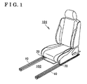
- Fig. 1 is a perspective view schematically illustrating a slide apparatus for a vehicle according to a first embodiment disclosed here;
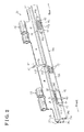
- Fig. 2 is a perspective view of an upper rail of the slide apparatus according to the first embodiment
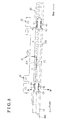
- Fig. 3 is a side view of the slide apparatus according to the first embodiment
- Fig. 4 is a cross-sectional view taken along the line IV-IV in Fig. 3 ;
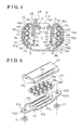
- Fig. 5 is an exploded perspective view illustrating a configuration of a ball circulation unit of the slide apparatus according to the first embodiment
- Fig. 6A is an exploded perspective view illustrating the configuration of the ball circulation unit according to a second embodiment disclosed here;
- Fig. 6B is a perspective view of a second case of the ball circulation unit according to the second embodiment
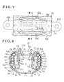
- Fig. 7 is a front view of the ball circulation unit according to the second embodiment.
- Fig. 8 is a cross-sectional view taken along the line VIII-VIII in Fig. 7 ;
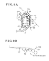
- Fig. 9A is an enlarged schematic view of a portion of Fig. 8 ;
- Fig. 9B is a diagram schematically illustrating a perspective view viewed from a direction of an arrow FA in Fig. 9 .
- a slide apparatus for a vehicle includes a pair of lower rails (right and left lower rails) 10 serving as a first rail, a pair of upper rails (right and left upper rails) 20 serving as a second rail, and a ball circulation unit 40 serving as a rolling element circulation unit.
- the pair of lower rails 10 is fixed to a vehicle floor 100 (vehicle) so as to extend in a longitudinal direction of the vehicle.
- the pair of upper rails 20 is fixed to a vehicle seat 101 and is movably supported relative to the pair of lower rails 10.
- the ball circulation unit 40 is attached to an attachment portion 21 formed at the upper rail 20.
- each of the lower rails 10 includes a bottom portion 11 formed to be in parallel to the vehicle floor 100, side portions 12 extending upwardly from both ends of the bottom portion 11, and folding portions 13 extending inwardly downwardly from both upper ends of the respective side portions 12.
- Inclined portions 12a are formed at upper and lower ends of the respective side portions 12 so as to be inclined inwardly. Inner side surfaces of the inclined portions 12a function as operating surfaces 12b.
- plural lock recess portions 13a are formed at each of the folding portions 13 so as to be arranged at predetermined intervals along the longitudinal direction of the vehicle.
- each of the upper rails 20 includes a first rail portion 20a and a second rail portion 20b.
- the first rail portion 20a includes a base plate portion 21 formed to be in parallel to the vehicle floor 100, a first connection plate 22a extending upwardly from one end of the base plate portion 21, a first folding portion 23a extending downwardly from the other end of the bottom portion 21.
- the first rail portion 20a also includes a first connecting portion 24a extending outwardly from a lower end of the first folding portion 23a and a first standing portion 25a (an outer side portion) extending upwardly from an outer end of the first connecting portion 24a.
- the second rail portion 20b includes a second connection plate 22b extending in a vertical direction of the vehicle, a second folding portion 23b extending downwardly from a lower end of the second connection plate 22b, a second connecting portion 24b extending outwardly from a lower end of the second folding portion 23b, and a second standing portion 25b (the outer side portion) extending upwardly from an outer end of the second connecting portion 24b.
- the first connection plate 22a of the first rail portion 20a and the second connection plate 22b of the second rail portion 20b are arranged to overlap each other to thereby form a void C surrounded by the base plate portion 21 and the first and second folding portions 23a and 23b.
- the upper rail 20 is configured in the aforementioned manner accordingly.
- fitting portions 26 are formed at front and rear sides respectively (i.e., two fitting portions 26 are provided) at the first and second connection plates 22a and 22b as illustrated in Fig. 2 so as to be fitted to the vehicle seat 101.
- a first bore 21 a is formed at a substantially center portion of the base plate portion 21 of the upper rail 20 in the longitudinal direction.
- a second bore 27 is formed so as to penetrate through the first and second folding portions 23a and 23b, and the first and second standing portions 25a and 25b of the upper rail 20.
- the second bore 27 is positioned slightly forward relative to the first bore 21 a in the longitudinal direction.
- a lock lever 31 is arranged within the void C of the upper rail 20.
- the lock lever 31 includes a lock portion 31 a extending in the longitudinal direction of the upper rail 20 and a lever portion 31 b bending from a rear end of the lock portion 31 a so as to extend upwardly.
- the lock lever 31 is connected to a front portion of the base plate portion 21 by means of an engagement pin 32 as illustrated in Figs. 2 and 4 .
- a portion of the lock portion 31 a is movable in the vertical direction within the second bore 27 with reference to the aforementioned connected portion of the lock lever 31 relative to the base plate portion 21.
- the lever portion 31 b penetrates through the first bore 21 a and extends upwardly from the base plate portion 21. Accordingly, in a case where the lever portion 31 b is operated downwardly as illustrated by an arrow F1 in Fig. 2 , the lock portion 31 a moves downward relative to the connected portion.
- the lock portion 31 a In a state where the upper rail 20 is assembled on the lower rail 10, the lock portion 31 a is engageable and disengageable relative to the lock recess portions 13a formed at the lower rail 10.
- the lock portion 31 a engages with the lock recess portions 13a when being positioned upwardly.
- the lock portion 31 a disengages from the lock recess portions 13a when moving downwardly from the upward position.
- attachment portions 28 are formed in the vicinity of both end portions of each of the first and second standing portions 25a and 25b of the upper rail 20 in the longitudinal direction.
- the ball circulation units 40 are mounted on the respective attachment portions 28.
- Each of the attachment portions 28 is constituted by a cut portion and both side portions of the cut portion formed at the standing portion 25a or 25b.
- two of the ball circulation units 40 are provided at the first standing portion 25a while two of the ball circulation units 40 are provided at the second standing portion 25b. That is, according to the present embodiment, four of the ball circulation units 40 in total are provided at each of the upper rails 20.
- each of the ball circulation units 40 includes a first case 41, a second case 42 engaging with the first case 41 so as to be assembled thereon, and plural balls 43 serving as a plurality of rolling elements accommodated within a receiving portion defined by the first and second cases 41 and 42.
- the first and second cases 41 and 42 are constituted so as to be engageable with each other by means of an adhesive, a fitting structure, or the like.
- the first case 41 is made of a metallic material while the second case 42 is made of a resin material.
- Flange portions 41 a are formed at both ends of the first case 41 in the longitudinal direction so as to extend from the second case 42 in a state where the first case 41 engages with the second case 42.
- the flange portions 41 a are fixed to the both side portions of the cut portion constituting the attachment portion 28.
- penetration bores 41 aa are formed at the respective flange portions 41 a while through-holes are formed at the both side portions of the cut portion of the upper rail 20.
- screws for example, are inserted into the penetration bores 41 aa and the through-holes so that the first case 41 is mounted on the attachment portion 28.
- the first case 41 is mounted on the attachment portion 28 in a state where a biasing member 51 is disposed between each of the flange portions 41 a and the attachment portion 28.
- the first case 41 is accommodated within the cut portion constituting the attachment portion 28.
- a pair of annular receiving portions 41 b serving as first and second annular receiving portions is formed at a surface of the first case 41 so as to face the second case 42.
- Each of the pair of annular receiving portions 41 b is constituted in such a manner that a groove having a semicircle shape in a cross section is annularly formed as illustrated in Fig. 5 .
- the pair of annular receiving portions 41 b is positioned to overlap in the vertical direction in a state where the ball circulation unit 40 is attached to the upper rail 20.
- Each of the pair of annular receiving portions 41 b is formed into an elongated annular shape elongated to both edges of the first case 41 where the flange portions 41 a are formed.
- a first partition wall portion 41 c is formed between the pair of annular receiving portions 41 b so that the balls 43 accommodated in one of the annular receiving portions 41 b are inhibited from making contact with the balls 43 accommodated in the other of the annular receiving portions 41 b.
- a pair of annular accommodating portions 42a serving as the first and second annular receiving portions and a second partition wall portion 42b are formed at a surface of the second case 42 so as to face the first case 41.
- the pair of annular accommodating portions 42a face the pair of annular receiving portions 41 b while the second partition wall portion 42b faces the first partition wall portion 41 c. Therefore, in a state where the first and second cases 41 and 42 engage with each other, the annular receiving portions 41 b and the annular accommodating portions 42a match each other while the first and second partition wall portions 41 c and 42b match each other to thereby constitute the receiving portion where the plural balls 43 are accommodated.
- the plural balls 43 are accommodated within the annular receiving portions 41 b and the annular accommodating portions 42a so as to roll and circulate therewithin.
- the balls 43 include metallic balls 43a serving as metallic rolling elements and resin balls 43b serving as resin rolling elements.
- the metallic balls 43a and the resin balls 43b are alternately arranged within each of the annular receiving portions 41b.
- the resin balls 43b are illustrated with hatching.
- Inclined portions 42c are formed at a surface of the second case 42 so as to face respective operating surfaces 12b of the lower rail 10 in a state where the ball circulation unit 40 is attached to the attachment portion 28 of the upper rail 20.
- the inclined portions 42c are formed at upper and lower portions of the second case 42 respectively.
- Elongated bores 42d are formed at the respective inclined portions 42c so as to extend in the longitudinal direction of the rails 10 and 20 and to be connected to the respective annular receiving portions 41 b.
- a portion of the plural balls 43, i.e., some of the plural balls 43 accommodated within the annular receiving portions 41 b are exposed from the elongated bores 42d.
- a width of each of the elongated bores 42d is specified to be smaller than a diameter of each of the balls 43 so that the balls 43 are inhibited from disengaging from the annular receiving portions 41 b.
- the elongated bore 42d is formed in such a manner that both end portions of the elongated bore 42d in the longitudinal direction are slightly curved while a center portion extends substantially linearly in the longitudinal direction.
- the annular receiving portions 41 b and the annular accommodating portions 42a are configured so that the balls 43 are arranged in a straight line in the vertical direction in a state where the ball circulation unit 40 is attached to the upper rail 20.
- the first case 41 is made of the metallic material while the second case 42 is made of the resin material.
- the first and second cases 41 and 42 are not limited to be made of the aforementioned materials. Both of the first and second cases 41 and 42 may be made of the resin material, the metallic material, or the like.
- the portion of the plural balls 43 (i.e., some of the plural balls 43) exposed from the elongated bores 42d makes contact with the operating surfaces 12b of the lower rail 10 and with inner surfaces of the annular receiving portions 41 b. Then, in a case where the upper rail 20 slidably moves relative to the lower rail 10 in the longitudinal direction, some of the balls 43 in contact with the operating surfaces 12b and the inner surfaces of the annular receiving portions 41 b and the other of the balls 43 accommodated within the annular receiving portions 41 b and the annular accommodating portions 42a roll and circulate.
- the balls 43 positioned at an inner side of the first case 41 move to an outer side of the first case 41 (i.e., a side where the elongated bores 42d are formed) while the balls 43 positioned at the outer side of the first case 41 move to the inner side thereof.
- the balls 43 sequentially repeat the aforementioned movement. Accordingly, the large and smooth sliding movement of the upper rail 20 relative to the lower rail 10 is obtained.
- the biasing members 51 are disposed between the flange portions 41 a and the attachment portion 28 in a case where the first case 41 is attached to the attachment portion 28 of the upper rail 20, a contact pressure generated at a contact portion between the balls 43, the operating surfaces 12b, and the inner surfaces of the annular receiving portions 41 b is absorbed by the biasing members 51. As a result, an increase of a contact resistance at the aforementioned contact portion is restrained and a further smooth sliding movement of the upper rail 20 is achieved.
- the plural balls 43 accommodated within the annular receiving portions 41 b and the annular accommodating portions 42a move and circulate within the annular receiving portions 41 b and the annular accommodating portions 42a while rolling and making contact with the operating surfaces 12b of the lower rail 10 and the inner surfaces of the annular receiving portions 41 b of the first case 41 in association with the sliding movement of the upper rail 20 relative to the lower rail 10. Therefore, the large and smooth sliding movement of the upper rail 20 relative to the lower rail 10 is achieved.
- the balls 43 roll while making contact with the operating surfaces 12b and the inner surfaces of the annular receiving portions 41 b of the lower rail 10.
- the balls 43 arranged within one of the annular receiving portions 41 b and one of the annular accommodating portions 42a matching each other are inhibited from making contact with the balls 43 arranged within the other of the annular receiving portions 41 b and the other of the annular accommodating portions 42a matching each other.
- the rolling circulation of the balls 43 is smoothly conducted, thereby restraining an occurrence of a rolling failure, a circulation failure, and the like of the balls 43.
- each of the ball circulation units 40 on the upper rail 20 is completed by attaching the flange portions 41 a of the first case 41 to the attachment portion 28 of the upper rail 20. Therefore, the ball circulation unit 40 is easily mounted on the upper rail 20.
- the biasing members 51 are disposed between the ball circulation unit 40 and the upper rail 20.
- the stress is reduced because of an elastic deformation of each of the biasing members 51.
- the decrease of the rolling performance of the balls 43 is appropriately restrained.
- the further smooth sliding movement of the upper rail 20 relative to the lower rail 10 is obtained.
- the balls 43 include the metallic balls 43a and the resin balls 43b which are alternately arranged each other.
- a contact noise between the adjacent balls 43 is restrained.
- the metallic balls 43a because of the metallic balls 43a, the strength of the ball circulation unit 40 is ensured.
- FIG. 6A to 9B A second embodiment will be explained with reference to Figs. 6A to 9B .
- the second embodiment differs from the first embodiment in a portion of the configuration of the ball circulation unit 40.
- a difference of the second embodiment from the first embodiment will be mainly explained.
- the same configurations of the second embodiment bear the same reference numerals as the first embodiment.
- each of the ball circulation units 40 includes the first case 41, the second case 42, and the plural balls 43.
- configurations of the pair of annular receiving portions 41 b and the pair of annular accommodating portions 42a, and shapes of the elongated bores 42d formed at the second case 42 are different from the first embodiment.
- the annular receiving portions 41 b and the annular accommodating portions 42a are configured in such a manner that a circulation path of the balls 43 is inclined (i.e., each of the annular receiving portions 41 b and the annular accommodating portions 42a includes an inclined circulation passage) so as to form a sharp angle relative to the operating surface 12b of the lower rail 10 in a cross section perpendicular to the extending direction of the rails 10 and 20 in a state where the ball circulation unit 40 is attached to the upper rail 20. More specifically, as illustrated in Figs.
- the annular receiving portions 41 b and the annular accommodating portions 42a are formed to be inclined in a direction where an angle ⁇ 1 defined between an extension of the circulation path of the balls 43 and the operating surface 12b in the cross section perpendicular to the extending direction of the rails 10 and 20 is an acute angle. That is, as compared to the first embodiment, the annular receiving portions 41 b and the annular accommodating portions 42a are configured so that the angle ⁇ 1 is more acute than the first embodiment. Accordingly, because a contact angle of each of the balls 43 relative to the operating surface 12b is small, a hitting sound of the ball 43 generated when the ball 43 makes contact with the operating surface 12b is appropriately restrained.
- Fig. 9B is a schematic view illustrating a relationship between the operating surface 12b of the upper rail 20 and the balls 43 when viewed from an arrow FA direction in Fig. 9A .
- the ball 43 makes contact with the operating surface 12b in a curved path.
- the annular receiving portions 41 b and the annular accommodating portions 42a are configured so that the circulation path of the balls 43 relative to the operating surfaces 12b forms the curved path (i.e., each of the annular receiving portions 41 b and the annular accommodating portions 42a includes a curved circulation passage). Accordingly, as illustrated in Fig.
- a straight line connecting a center of the ball 43 that is in a state immediately after making contact with the operating surface 12b to a center of the ball 43 arranged adjacent to the aforementioned ball 43 and in the non-contact state relative to the operating surface 12b forms an angle ⁇ 2 relative to the operating surface 12b.
- an approach angle of the ball 43 when the ball 43 makes contact with the operating surface 12b is smaller than the angle ⁇ 2. Consequently, the hitting sound generated when the ball 43 makes contact with the operating surface 12b is appropriately restrained.
- the approach angle of the ball 43 relative to the operating surface 12b decreases in association with a decrease of a vertical distance D between the balls 43 adjacent to each other.
- the distance D is reduced without a change in distance between the centers of the balls 43.
- both the center portions of the elongated bores 42d of the second case 42 are slightly curved so as to be away from each other. At this time, however, such curved shape of the elongated bore 42d is not necessary and the elongated bore 42d may have the same configuration as that of the first embodiment.
- the inclined circulation passage and the curved circulation passage are provided at the annular receiving portions 41 b and the annular accommodating portions 42a, the approach angle of each of the balls 43 relative to the operating surface 12b of the lower rail 10 in a case where the ball 43 is brought to the contact state from the non-contact state relative to the operating surface 12b is reduced. Therefore, the ball 43 gradually makes contact with the operating surface 12b, which reduces the hitting sound generated when the ball 43 makes contact with the operating surface 12b.
- the curved circulation passage is easily provided.
- the inclined circulation passage and the curved circulation passage collectively effectively reduce the hitting sound generated when the ball 43 makes contact with the operating surface 12b.
- the annular receiving portions 41 b and the annular accommodating portions 42a may include either the inclined circulation passage or the curved circulation passage. Even in such case, the approach angle of the ball 43 relative to the operating surface 12b of the lower rail 10 is reduced, thereby restraining the hitting sound of the ball 43 relative to the operating surface 12b.
- the flange portions 41 a are provided at the first case 41 of each of the ball circulation units 40 and are attached to the attachment portion 28 of the upper rail 20.
- the similar flange portions may be provided at the second case 42 so that both of the first and second cases 41 and 42 area attachable relative to the attachment portion 28.
- the flange portions are only provided at the second case 42 while the flange portions 41 a of the first case 41 are omitted. Then, the second case 42 is attached to the attachment portion 28 so that the ball circulation unit 40 is fixed to the upper rail 20.
- the biasing members 51 are not necessarily provided.
- the balls 43 include the metallic balls 43a and the resin balls 43b in a state where the metallic balls 43a and the resin balls 43b are alternately arranged.
- the balls 43 may only include the metallic balls 43a or the resin balls 43b.
- the first case 41 and the second case 42 constituting the ball circulation unit 40 may be both made of the metallic material or the resin material.
- the slide apparatus is configured so that the vehicle seat is slidably movable in the longitudinal direction of the vehicle.
- the slide apparatus is not limited to have the aforementioned configuration and may be configured so that the vehicle seat is movable in a width direction of the vehicle, so that the vehicle seat is rotatable, or the like.
- the first rail is not limited to the lower rail 10 while the second rail is not limited to the upper rail 20.
- the first rail may be the upper rail 20 while second rail may be the lower rail 10.
Landscapes
- Engineering & Computer Science (AREA)
- Aviation & Aerospace Engineering (AREA)
- Transportation (AREA)
- Mechanical Engineering (AREA)
- Seats For Vehicles (AREA)
- Bearings For Parts Moving Linearly (AREA)
Applications Claiming Priority (1)
| Application Number | Priority Date | Filing Date | Title |
|---|---|---|---|
| JP2010217139A JP5621472B2 (ja) | 2010-09-28 | 2010-09-28 | 車両用スライド装置、及びスライド装置用転動体循環ユニット |
Publications (2)
| Publication Number | Publication Date |
|---|---|
| EP2436552A2 true EP2436552A2 (fr) | 2012-04-04 |
| EP2436552A3 EP2436552A3 (fr) | 2018-01-17 |
Family
ID=44651420
Family Applications (1)
| Application Number | Title | Priority Date | Filing Date |
|---|---|---|---|
| EP11181863.9A Withdrawn EP2436552A3 (fr) | 2010-09-28 | 2011-09-19 | Appareil coulissant pour véhicule et son unité de circulation d'élément roulant |
Country Status (4)
| Country | Link |
|---|---|
| US (1) | US8844891B2 (fr) |
| EP (1) | EP2436552A3 (fr) |
| JP (1) | JP5621472B2 (fr) |
| CN (1) | CN102416887B (fr) |
Families Citing this family (27)
| Publication number | Priority date | Publication date | Assignee | Title |
|---|---|---|---|---|
| JP5434102B2 (ja) * | 2009-01-29 | 2014-03-05 | アイシン精機株式会社 | 車両用シートスライド装置 |
| JP5327002B2 (ja) * | 2009-11-05 | 2013-10-30 | アイシン精機株式会社 | 車両用シートスライド装置 |
| US8556221B2 (en) * | 2010-11-08 | 2013-10-15 | Taco Metals, Inc. | Roller mount for seat |
| JP2013023039A (ja) * | 2011-07-19 | 2013-02-04 | Aisin Seiki Co Ltd | シートスライド装置 |
| DE102012201274A1 (de) * | 2012-01-30 | 2013-08-01 | Lear Corporation | Sitzschienenmechanismus |
| WO2014104344A1 (fr) * | 2012-12-28 | 2014-07-03 | Thk株式会社 | Dispositif de glissière de siège pour véhicule |
| JP6127729B2 (ja) * | 2013-05-30 | 2017-05-17 | アイシン精機株式会社 | 車両用シートスライド装置 |
| DE102015226266B4 (de) * | 2015-12-21 | 2019-07-11 | Adient Luxembourg Holding S.À R.L. | Lagerkäfig und Sitzschienenpaar für einen Fahrzeugsitz |
| JP2017171044A (ja) * | 2016-03-22 | 2017-09-28 | アイシン精機株式会社 | 車両用スライド装置、及びスライド装置用転動体循環ユニット |
| JP2017171046A (ja) * | 2016-03-22 | 2017-09-28 | アイシン精機株式会社 | 車両用スライド装置、及びスライド装置用転動体循環ユニット |
| JP2017171045A (ja) * | 2016-03-22 | 2017-09-28 | アイシン精機株式会社 | 車両用スライド装置、及びスライド装置用転動体循環ユニット |
| JP6620673B2 (ja) * | 2016-05-25 | 2019-12-18 | トヨタ紡織株式会社 | 乗物用スライド装置 |
| JP2018012408A (ja) | 2016-07-20 | 2018-01-25 | アイシン精機株式会社 | 車両用シートスライド装置 |
| GB2555141A (en) * | 2016-10-21 | 2018-04-25 | Accuride Int Ltd | A sliding support assembly |
| DE102017007844B4 (de) * | 2017-08-18 | 2022-01-05 | Audi Ag | Fahrzeugsitz für ein Kraftfahrzeug und Kraftfahrzeug |
| DE102019206304B4 (de) * | 2018-05-04 | 2022-01-27 | Lear Corporation | Schienenanordnung |
| US11584264B2 (en) | 2018-10-09 | 2023-02-21 | Magna Seating Inc | Long rail assembly with side opening for vehicle seat adjustment |
| CA3115975A1 (fr) | 2018-10-11 | 2020-04-16 | Magna Seating Inc. | Ensemble de rail long pour reglage de siege de vehicule |
| EP3844020B1 (fr) | 2018-10-19 | 2023-08-23 | Magna Seating Inc. | Siège amovible utilisé avec un ensemble rail long |
| EP3853063B1 (fr) | 2018-12-11 | 2023-11-15 | Magna Seating Inc. | Connexion d'alimentation électrique pour ensemble rail long de courant |
| CA3123867A1 (fr) | 2018-12-17 | 2020-06-25 | Magna Seating Inc. | Liberation d'un verrouillage a boucle pour ensemble a long rail d'alimentation |
| US12071044B2 (en) | 2019-03-14 | 2024-08-27 | Magna Seating Inc. | Long rail assembly with internal power driving system |
| CA3138998A1 (fr) | 2019-05-03 | 2020-11-12 | Magna Seating Inc. | Ensemble rail long a configuration de rail triple |
| CA3098743A1 (en) | 2019-11-11 | 2021-05-11 | Magna Seating Inc. | Long rail assembly with retention latch |
| WO2021155338A1 (fr) | 2020-01-31 | 2021-08-05 | Magna Seating Inc. | Boîte de vitesses à ressort pour ensemble rail long d'alimentation |
| CA3166931A1 (fr) | 2020-02-07 | 2021-08-12 | Magna Seating Inc. | Systeme de transmission pour ensemble de long rail d'alimentation |
| KR102501242B1 (ko) * | 2020-11-18 | 2023-02-16 | 케이비아이동국실업 주식회사 | 슬라이딩형 글로브 박스 |
Citations (2)
| Publication number | Priority date | Publication date | Assignee | Title |
|---|---|---|---|---|
| JPH0971157A (ja) | 1995-09-05 | 1997-03-18 | Shiroki Corp | シートスライド装置 |
| WO2010002421A1 (fr) | 2008-07-03 | 2010-01-07 | Robert Abrams | Nébuliseur semi-automatique de dose de médicamentation d'urgence |
Family Cites Families (16)
| Publication number | Priority date | Publication date | Assignee | Title |
|---|---|---|---|---|
| JPH01121712A (ja) | 1987-11-06 | 1989-05-15 | Nkk Corp | 被検査物内面の減肉部検出方法 |
| JPH01121712U (fr) * | 1988-02-10 | 1989-08-17 | ||
| JP3344131B2 (ja) * | 1994-12-16 | 2002-11-11 | 日本精工株式会社 | 自己潤滑リニアガイド装置 |
| US5809834A (en) * | 1996-06-14 | 1998-09-22 | Mrba Company | Motion roller bearing assembly |
| FR2755653B1 (fr) * | 1996-11-14 | 1999-01-08 | Faure Bertrand Equipements Sa | Glissiere pour siege de vehicule, et siege equipe d'une telle glissiere |
| GB2364632B (en) * | 2000-07-13 | 2003-12-03 | Johnson Controls Gmbh | Track assembly |
| US20030206669A1 (en) * | 2000-07-13 | 2003-11-06 | Smith Rodger G. | Track assembly |
| US7614793B2 (en) * | 2002-11-27 | 2009-11-10 | The Anspach Effort, Inc | Needle/roller bearing |
| JP2005155798A (ja) * | 2003-11-26 | 2005-06-16 | Nsk Ltd | リニアガイド装置 |
| CN100554708C (zh) * | 2005-03-24 | 2009-10-28 | Thk株式会社 | 薄型滑动单元 |
| GB2437911B (en) | 2006-05-09 | 2008-03-26 | King Slide Works Co Ltd | Supporting structure for a slide assembly |
| JP4633106B2 (ja) * | 2007-11-30 | 2011-02-16 | 国立大学法人長岡技術科学大学 | 直動装置 |
| TWI353821B (en) * | 2008-03-21 | 2011-12-11 | King Slide Works Co Ltd | Slide rail assembly |
| JP4743345B2 (ja) * | 2008-08-27 | 2011-08-10 | アイシン精機株式会社 | 車両用スライド装置 |
| CN201472187U (zh) * | 2009-07-13 | 2010-05-19 | 浙江俱进汽摩配件有限公司 | 汽车座椅滑轨的滑动装置 |
| JP5327002B2 (ja) * | 2009-11-05 | 2013-10-30 | アイシン精機株式会社 | 車両用シートスライド装置 |
-
2010
- 2010-09-28 JP JP2010217139A patent/JP5621472B2/ja not_active Expired - Fee Related
-
2011
- 2011-09-19 EP EP11181863.9A patent/EP2436552A3/fr not_active Withdrawn
- 2011-09-19 US US13/235,907 patent/US8844891B2/en not_active Expired - Fee Related
- 2011-09-27 CN CN201110294025.3A patent/CN102416887B/zh not_active Expired - Fee Related
Patent Citations (2)
| Publication number | Priority date | Publication date | Assignee | Title |
|---|---|---|---|---|
| JPH0971157A (ja) | 1995-09-05 | 1997-03-18 | Shiroki Corp | シートスライド装置 |
| WO2010002421A1 (fr) | 2008-07-03 | 2010-01-07 | Robert Abrams | Nébuliseur semi-automatique de dose de médicamentation d'urgence |
Also Published As
| Publication number | Publication date |
|---|---|
| CN102416887B (zh) | 2015-09-30 |
| US8844891B2 (en) | 2014-09-30 |
| JP5621472B2 (ja) | 2014-11-12 |
| US20120074288A1 (en) | 2012-03-29 |
| JP2012071656A (ja) | 2012-04-12 |
| CN102416887A (zh) | 2012-04-18 |
| EP2436552A3 (fr) | 2018-01-17 |
Similar Documents
| Publication | Publication Date | Title |
|---|---|---|
| EP2436552A2 (fr) | Appareil coulissant pour véhicule et son unité de circulation d'élément roulant | |
| US9126505B2 (en) | Seat slide apparatus | |
| US8556222B2 (en) | Seat slide device for vehicle | |
| US8033520B2 (en) | Vehicle seat slide mechanism | |
| CN104334403B (zh) | 座椅滑动装置 | |
| CN203819069U (zh) | 座椅滑动装置 | |
| EP2418118B1 (fr) | Glissière de siège | |
| EP2767432A1 (fr) | Coulisse pour siège de véhicule | |
| US10221889B2 (en) | Slide rail assembly | |
| CN112996414B (zh) | 引导装置 | |
| CN100408373C (zh) | 滑动装置 | |
| EP2039561A2 (fr) | Appareil coulissant de siège pour véhicule | |
| JP2018052268A (ja) | シート用スライド装置 | |
| JP2018099997A (ja) | 直動案内装置 | |
| US20120181408A1 (en) | Vehicle seat slide mechanism | |
| US20170341534A1 (en) | Seat sliding device | |
| JP6883984B2 (ja) | 運動案内装置及び航空機用座席 | |
| WO2011123091A1 (fr) | Ensemble de glissières de siège | |
| JP6473604B2 (ja) | スライドレール及び遊技機 | |
| KR100847130B1 (ko) | 리니어 모션 슬림 슬라이더 | |
| JP2020026156A (ja) | シートスライド装置 | |
| US8419280B2 (en) | Thin slide unit | |
| US11235683B2 (en) | Vehicle seat slide apparatus | |
| EP2901891B1 (fr) | Ensemble coulissant | |
| JP2017065665A (ja) | 車両用シートスライド装置及び車両用シートスライド装置の製造方法 |
Legal Events
| Date | Code | Title | Description |
|---|---|---|---|
| PUAI | Public reference made under article 153(3) epc to a published international application that has entered the european phase |
Free format text: ORIGINAL CODE: 0009012 |
|
| AK | Designated contracting states |
Kind code of ref document: A2 Designated state(s): AL AT BE BG CH CY CZ DE DK EE ES FI FR GB GR HR HU IE IS IT LI LT LU LV MC MK MT NL NO PL PT RO RS SE SI SK SM TR |
|
| AX | Request for extension of the european patent |
Extension state: BA ME |
|
| STAA | Information on the status of an ep patent application or granted ep patent |
Free format text: STATUS: REQUEST FOR EXAMINATION WAS MADE |
|
| 17P | Request for examination filed |
Effective date: 20170309 |
|
| RBV | Designated contracting states (corrected) |
Designated state(s): AL AT BE BG CH CY CZ DE DK EE ES FI FR GB GR HR HU IE IS IT LI LT LU LV MC MK MT NL NO PL PT RO RS SE SI SK SM TR |
|
| PUAL | Search report despatched |
Free format text: ORIGINAL CODE: 0009013 |
|
| AK | Designated contracting states |
Kind code of ref document: A3 Designated state(s): AL AT BE BG CH CY CZ DE DK EE ES FI FR GB GR HR HU IE IS IT LI LT LU LV MC MK MT NL NO PL PT RO RS SE SI SK SM TR |
|
| AX | Request for extension of the european patent |
Extension state: BA ME |
|
| RIC1 | Information provided on ipc code assigned before grant |
Ipc: B60N 2/07 20060101AFI20171211BHEP |
|
| STAA | Information on the status of an ep patent application or granted ep patent |
Free format text: STATUS: EXAMINATION IS IN PROGRESS |
|
| 17Q | First examination report despatched |
Effective date: 20190711 |
|
| GRAP | Despatch of communication of intention to grant a patent |
Free format text: ORIGINAL CODE: EPIDOSNIGR1 |
|
| STAA | Information on the status of an ep patent application or granted ep patent |
Free format text: STATUS: GRANT OF PATENT IS INTENDED |
|
| INTG | Intention to grant announced |
Effective date: 20191220 |
|
| RIN1 | Information on inventor provided before grant (corrected) |
Inventor name: YAMADA, YUKIFUMI Inventor name: ISOBE, SHINYA |
|
| STAA | Information on the status of an ep patent application or granted ep patent |
Free format text: STATUS: THE APPLICATION IS DEEMED TO BE WITHDRAWN |
|
| 18D | Application deemed to be withdrawn |
Effective date: 20200603 |