EP2436559A1 - Agencement d'entraînement pour un rétroviseur extérieur d'un véhicule - Google Patents
Agencement d'entraînement pour un rétroviseur extérieur d'un véhicule Download PDFInfo
- Publication number
- EP2436559A1 EP2436559A1 EP10075606A EP10075606A EP2436559A1 EP 2436559 A1 EP2436559 A1 EP 2436559A1 EP 10075606 A EP10075606 A EP 10075606A EP 10075606 A EP10075606 A EP 10075606A EP 2436559 A1 EP2436559 A1 EP 2436559A1
- Authority
- EP
- European Patent Office
- Prior art keywords
- gear
- movable part
- mirror
- drive arrangement
- arrangement according
- Prior art date
- Legal status (The legal status is an assumption and is not a legal conclusion. Google has not performed a legal analysis and makes no representation as to the accuracy of the status listed.)
- Withdrawn
Links
- 230000033001 locomotion Effects 0.000 claims abstract description 24
- 238000009434 installation Methods 0.000 claims 1
- 210000000078 claw Anatomy 0.000 description 4
- 230000006835 compression Effects 0.000 description 4
- 238000007906 compression Methods 0.000 description 4
- 230000008878 coupling Effects 0.000 description 4
- 238000010168 coupling process Methods 0.000 description 4
- 238000005859 coupling reaction Methods 0.000 description 4
- 230000005540 biological transmission Effects 0.000 description 2
- 208000012886 Vertigo Diseases 0.000 description 1
- 230000000712 assembly Effects 0.000 description 1
- 238000000429 assembly Methods 0.000 description 1
- 238000005452 bending Methods 0.000 description 1
- 230000001419 dependent effect Effects 0.000 description 1
- 239000011521 glass Substances 0.000 description 1
- 238000000034 method Methods 0.000 description 1
- 238000004804 winding Methods 0.000 description 1
Images


Classifications
-
- B—PERFORMING OPERATIONS; TRANSPORTING
- B60—VEHICLES IN GENERAL
- B60R—VEHICLES, VEHICLE FITTINGS, OR VEHICLE PARTS, NOT OTHERWISE PROVIDED FOR
- B60R1/00—Optical viewing arrangements; Real-time viewing arrangements for drivers or passengers using optical image capturing systems, e.g. cameras or video systems specially adapted for use in or on vehicles
- B60R1/02—Rear-view mirror arrangements
- B60R1/06—Rear-view mirror arrangements mounted on vehicle exterior
- B60R1/062—Rear-view mirror arrangements mounted on vehicle exterior with remote control for adjusting position
- B60R1/07—Rear-view mirror arrangements mounted on vehicle exterior with remote control for adjusting position by electrically powered actuators
- B60R1/074—Rear-view mirror arrangements mounted on vehicle exterior with remote control for adjusting position by electrically powered actuators for retracting the mirror arrangements to a non-use position alongside the vehicle
Definitions
- the invention relates to a drive arrangement for an exterior rearview mirror of a vehicle for moving a mirror head relative to a mirror connected to the vehicle mirror according to the preamble of the main claim.
- a plurality of drive assemblies for exterior rearview mirror of a motor vehicle is known, by means of which a mirror glass-carrying mirror head from a driving position in which the outside mirror is folded out to the central axis of the motor vehicle, and a parking position in which the mirror head in the direction of the central axis the vehicle is moved, and vice versa.
- a gap between the mirror head and the mirror base which, however, generates wind noise.
- this seal complicates the rotation of the mirror head due to the additional friction.
- the mirror head in the movement from the driving position to raise the parking position relative to the mirror, wherein the lifting is realized by means of two respectively fixedly connected to the mirror and mirror head and arranged around the axis of rotation rings, respectively ramps and Have grooves that mesh in the driving position, and slide on each other when turning in the parking position, while lifting the head of the mirror.
- the invention has for its object to provide a drive arrangement for an exterior rearview mirror, with a controlled lifting of the mirror head from the mirror is possible, the friction is reduced in the lifting and the transmission is relieved.
- a drive arrangement for an exterior rearview mirror for moving a mirror head relative to a fixed mirror foot means for lifting a connectable to the mirror head to a
- the running elements are arranged on a sleeve-shaped carrier, which engages over the end face of the gear in a flange-like manner and is fixedly connected to the movable part or is part of the movable part.
- this movable part includes, for example, the housing of the drive assembly.
- the running elements preferably three, are mounted on the flange area and work with the end face, which preferably also comprises three ramps together.
- the running elements may be formed as sliders or as rollers, wherein the slider lifts are attached to the end face of the underside facing the flange of the carrier or integrally connected thereto and the rollers are mounted in the carrier, such that the slider lifts on the face slide and the roles can run on it.
- the movable part and / or the sleeve-like carrier the when using rollers is also referred to as a roller carrier, at least one locking element which engages in the driving position in a arranged on the fixed part locking recess.
- the carrier has at the same time the task of locking with the fixed part, whereby a rotational movement of the carrier or the adjuster housing (movable part) and thus also the mirror head is prevented in the driving position.
- the gear wheel with respect to the fixed part to a predetermined freedom from rotation, which corresponds at least in the pitch path of the ramp-like increase.
- the locking of the movable part with the fixed part of the drive assembly can be specifically solved before the actual movement of the movable part from the driving position in the parking position, so that controlled, successive movements are given.
- the angle between the lowest part and the highest part of the ramp, i. the part in front of and behind the ramp, the angle of freedom of rotation and thus the travel required by the at least one locking element to disengage from the locking recess, i. the ramp length dictates the freedom of rotation of the gear and the ramp height must be at least equal to but preferably slightly greater than the lock height.
- a spring preferably a torsion spring, wherein the frictional forces between the movable part, gear and fixed part and the spring force of the spring and the coil spring, which is arranged for applying a biasing force to the gear on the movable part , adapted to each other, that the spring supports the lifting of the movable part of the fixed part in the movement from the driving position to the parking position and the rotation of the gear according to a predetermined rotational freedom in the movement from the parking position into the driving position difficult.
- This measure prevents the following problem. To unfold the mirror, it is necessary to reverse the direction of rotation of the motor of the drive.
- the gear has some freedom of rotation with respect to the fixed part in this direction, which when folding was used to raise the mirror. Depending on the frictional forces occurring either the mirror head will stand still and the gear is rotated or vice versa. This can lead to an uncontrolled or unaesthetic movement. If the gear is first twisted and then only the mirror head, it comes that the mirror head or the movable part wants to lower before reaching the driving position. A lowering is not possible because the locking elements on the carrier or roller carrier or the moving part and the fixed part can only engage exactly in the driving position. If the mirror head reached the driving position in which the locking can take place, a sudden lowering would take place. This causes a loud noise and is therefore unacceptable.
- auxiliary torque should remain as constant as possible during lifting. With the given geometry, this is best achieved with a torsion spring.
- a further embodiment provides that a spring-loaded latching element, preferably a latching pin, is accommodated in the movable part, which predetermines the drive position with a stop arranged on the fixed part.
- the fixed part preferably has a locking disk with stops on which the at least spring-loaded locking pin can slide until a stop is reached.
- the fixed part has a latching disc with at least one radial groove, preferably three grooves, for receiving a rocker prestressed by a spring, the rocker being next to one another in the radial direction arranged arranged cam with different Aufstellwinkeln.
- the other of the cam engages after lifting the movable part in a provided on the gear locking recess, which is only possible when the movable part is fully raised.
- This cam replaces the locking pin of the previous embodiment.
- the decoupling of the motion sequences is more form-fitting than when using a torsion spring (purely non-positively).
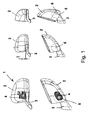
- Fig. 1 are different positions of an outside mirror 1 shown during Abklappvorgang between a driving position in a parking position.
- the mirror 1 has a mirror head 2 with not shown mirror glass, a mirror 3, which is connected to a motor vehicle, not shown, and arranged between the mirror head 2 and mirror 3 drive arrangement 4 for controlling the movement of the mirror head relative to the mirror.
- Left and center in the Fig. 1 is the mirror head 2 in its driving position, wherein it is centrally lifted from the mirror, so that a gap H between the mirror head 2 and mirror 3 is generated.
- Fig. 1 on the right is the mirror head 2 in the parking position in which it is folded down to the motor vehicle, wherein the movement or the rotation about the axis of rotation 5 of the drive 4 is indicated by the arrow 6. In this position, the mirror head 2 continues to the mirror 3 on the gap H.
- the positions are to be run in exactly the reverse order.
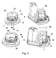
- Fig. 2 is a section through the drive assembly 4 is shown.
- a locking plate 7 is provided, which is connected to the not shown in this figure mirror 3.
- a movable part 8 is provided, which is composed of several components, namely a housing 9, a housing connected to the lid 10 and a sleeve-like roller carrier 11, on which a plurality of rollers 12, in the embodiment, three rollers are mounted ,
- the roller carrier is in the Fig. 2 shown as a separate component which is bolted to the housing 9, but it may also be formed as part of the housing 9.
- a driven gear 13 is accommodated, which is at least partially movable relative to the roller carrier 11 and which is driven by a worm 14.
- a spring-loaded locking pin 15 can be seen, which serves to determine the driving position of the mirror head 2 and thus of the movable part 8.
- Fig. 3a the roller carrier 11 is shown separately with driven gear 13 and locking disk 7, while in Fig. 3b the entire drive assembly 4, partially cut in the driving position can be seen.
- the locking disk has a plurality of slides 16 for the locking pin 15, which by a Stop 17 are limited.
- the locking disc 7 is provided with lugs 18, which serve on the one hand to limit the movement of the driven gear 13 and on the other hand each locking recesses 19 which can engage with arranged on the roller carrier 11 locking fingers 20.
- the driven gear 13 is provided on the latching disc 7 associated sides with lugs 21, which serve to support on the locking plate 7.
- the driven gear 13 can move relative to the locking disk 7, is between the lugs 18 of the locking disk 7 and the lugs 21 of the gear 13 a Game 22 predetermined that specifies a rotational freedom of the gear 13 relative to the locking disk.
- a spiral spring 24 can be seen, which presses on the housing 9 and the roller carrier 11 and which defines a biasing force on the output gear 13.
- the spring-loaded detent pin 15 is in the driving position on the stop 17 of the locking disc 7.
- the fingers 20 at the lower end of the roller carrier 11, which is fixedly connected to the housing 9, are in engagement with the locking recesses or slots in the locking disc and prevent rotational movement of the roller carrier 11 and the housing 9 of the Spiegelverstellers and thus the mirror head.
- the rollers 12 are located at the lowest point of the ramps of the output gear 13.
- Fig. 3b is an electric motor 25 and to detect the surrounding housing, which drives the worm 14.
- the drive arrangement 4 is on the one hand in the raised position of the movable part 8 with respect to the fixed part (a) designed as a locking disk 7 and on the other hand in the folded-down state in the parking position (b). If the Drive assembly 4 is to bring the mirror head 2 in the park position, drives the motor 25 via the worm 14 to the output gear 13, which is in the in Fig. 4a shown direction 26 is twisted until the lugs 18 and 21 each of the locking disk and the driven gear abut each other and the freedom from rotation is used up by the game 22.
- Fig. 5 shows the parking position at the beginning of the folding back of the mirror head 2, which is indicated by the arrows 30.
- the torsion spring 29 or Aufziehfeder which is under a certain bias, makes it difficult to turn back the output gear 13 during the unfolding of the mirror head 2, so that first the movable member 8 is rotated. Reached the moving part 8, the driving position, its further rotation is prevented by the locking pin 15, which again engages with the stop 17 in engagement.
- the output gear 13 is now rotated against the spring tension of the torsion spring 29 until its given by the game 22 freedom from rotation is used up. In this case, the mirror head or the movable part 8 is lowered slowly over the ramps 23.
- This torsion spring 29 then supports the lifting of the movable part 8 and the mirror head 2 again at the beginning of the Abklappvorgangs.
- the torsion spring 29 relaxed to the biasing force, which thereby helps in lifting and the axial compression spring 24 of the Mirror drive is stretched around the lifting height.
- folding is as well as the subsequent unfolding a constant force in the torsion spring and the compression spring.
- lowering the torsion spring 29 is stretched and relaxed the axial compression spring 24 to the lifting height.
- FIGS. 6 and 7 Another possibility is shown to determine the desired sequence of movements in the Fold in and unfold the mirror head to get.
- a fixed part locking disk 31 is used ( Fig. 6a ), which has three radial bores 32 with niksegmentartigem cross-section, in each of which a cylindrical rocker 33 is received.
- the rocker 33 is formed as a cylinder segment which can rotate slightly in the respective radial bore 32 about its own axis.
- the rocker has at its inwardly directed end respectively radially adjacent cams, a radially inner cam 34 and a radially outer cam 35, wherein the inner cam 34 projects slightly beyond the flat side of the rocker and both cams 34, 35 to each other have different inclinations or angles.
- a spring, preferably a leaf spring 36 holds the rocker in a preferred position. This position is characterized by how the non-explosively illustrated rockers 33 show that the inner cam 34 are placed and the outer cam 35 are flush with the surface of the locking disc 31.
- Fig. 6b an output gear 13 is shown, which differs from that of the previous in that in the game 22 predetermining area between the lugs 18 a serrated recess 37 for receiving a radially outer cam 35 is arranged.
- Fig. 7 in turn, the drive assembly 4 is shown in different positions, in Fig. 7a in the driving position position, in Fig. 7b the drive assembly when lifting the mirror head and Fig. 7c when folding.
- Fig. 7a has the roller carrier 11 or the housing on the locking disk 31 facing End three recesses 36, in which the inner cam 34 can engage in the driving position and thus prevent rotation of the mirror head.
- the drive gear 13 rests on the outer cam 35 of the rockers 33 and prevents rotation of the rockers 33. If the output gear 13 according to Fig. 7b driven, are raised by the ramps of the end face of the roller carrier 11 and the housing 8 upwards, wherein the inner cam 34 prevents rotation of the movable part or the mirror head during the lifting operation.
- FIGS. 7b and 7c show the drive assembly at the beginning and during Einklappvorgang, wherein after the exit of the inner cam 34 from the recess 36, the movable member is rotated and by the rotational movement, the inner cam 34 of the rockers 33 are folded over and the outer cam 35 set up.
- This is only possible if the mirror head 2 or the movable part is completely lifted from the fixed part or the locking disk 31, since only in this position, ie if the rotational freedom of the output gear is completely exhausted, the recess 37 in the output gear 13 a Rotation of rockers 33 allowed (see arrow 38).
- the driven gear 13 is now prevented by the outer cam 35 from rotating.
- the recesses 36 coincide with the inner cams 34 of the rockers 33, and the leaf springs 36 cause the rockers 33 to rotate back into their initial position. As a result, a further rotation of the movable part is prevented and at the same time the output gear 13 is released, which can then lower the mirror head in the driving position.
- the sleeve-like carrier is formed as a roller carrier 11, on which the running on the end face of the gear 13 rollers 12 are rotatably mounted.
Landscapes
- Engineering & Computer Science (AREA)
- Multimedia (AREA)
- Mechanical Engineering (AREA)
- Rear-View Mirror Devices That Are Mounted On The Exterior Of The Vehicle (AREA)
Priority Applications (1)
| Application Number | Priority Date | Filing Date | Title |
|---|---|---|---|
| EP10075606A EP2436559A1 (fr) | 2010-10-01 | 2010-10-01 | Agencement d'entraînement pour un rétroviseur extérieur d'un véhicule |
Applications Claiming Priority (1)
| Application Number | Priority Date | Filing Date | Title |
|---|---|---|---|
| EP10075606A EP2436559A1 (fr) | 2010-10-01 | 2010-10-01 | Agencement d'entraînement pour un rétroviseur extérieur d'un véhicule |
Publications (1)
| Publication Number | Publication Date |
|---|---|
| EP2436559A1 true EP2436559A1 (fr) | 2012-04-04 |
Family
ID=43531114
Family Applications (1)
| Application Number | Title | Priority Date | Filing Date |
|---|---|---|---|
| EP10075606A Withdrawn EP2436559A1 (fr) | 2010-10-01 | 2010-10-01 | Agencement d'entraînement pour un rétroviseur extérieur d'un véhicule |
Country Status (1)
| Country | Link |
|---|---|
| EP (1) | EP2436559A1 (fr) |
Cited By (5)
| Publication number | Priority date | Publication date | Assignee | Title |
|---|---|---|---|---|
| DE102013201434B3 (de) * | 2013-01-29 | 2014-05-28 | Mekra Lang Gmbh & Co. Kg | Elektrisch rotatorische Verstelleinheit sowie indirektes Sichtsystem für Fahrzeuge mit einer solchen Verstelleinheit |
| EP3150438A1 (fr) * | 2015-09-29 | 2017-04-05 | Fico Mirrors S.A. | Système de rétroviseur rabattable pour véhicules à moteur |
| DE102019101086B3 (de) * | 2019-01-16 | 2020-03-26 | Motherson Innovations Company Limited | Kompaktes Antriebsklappsystem mit Gleichstrommotor, Rückblickvorrichtung sowie Verfahren zum Einklappen und Ausklappen derselben |
| US10940801B1 (en) | 2019-09-09 | 2021-03-09 | Motherson Innovations Company Limited | Actuating device for a component |
| CN120251671A (zh) * | 2025-06-09 | 2025-07-04 | 合肥昊翔智能科技股份有限公司 | 传动齿轮结构及用于车辆视觉装置的折叠装置 |
Citations (3)
| Publication number | Priority date | Publication date | Assignee | Title |
|---|---|---|---|---|
| EP0931699A1 (fr) | 1997-08-20 | 1999-07-28 | Kabushiki Kaisha Tokai Rika Denki Seisakusho | Unite motorisee d'entrainement d'un retroviseur exterieur de vehicule |
| WO2003011642A1 (fr) * | 2001-08-02 | 2003-02-13 | Iku Holding Montfoort B.V. | Structure de charniere et actionneur a charniere, en particulier pour retroviseur exterieur d'un vehicule a moteur |
| US20070029179A1 (en) * | 2004-02-06 | 2007-02-08 | Eaton Automotive B.V. | Hinge actuator and method for adjusting two parts of a hinge actuator relative to each other |
-
2010
- 2010-10-01 EP EP10075606A patent/EP2436559A1/fr not_active Withdrawn
Patent Citations (3)
| Publication number | Priority date | Publication date | Assignee | Title |
|---|---|---|---|---|
| EP0931699A1 (fr) | 1997-08-20 | 1999-07-28 | Kabushiki Kaisha Tokai Rika Denki Seisakusho | Unite motorisee d'entrainement d'un retroviseur exterieur de vehicule |
| WO2003011642A1 (fr) * | 2001-08-02 | 2003-02-13 | Iku Holding Montfoort B.V. | Structure de charniere et actionneur a charniere, en particulier pour retroviseur exterieur d'un vehicule a moteur |
| US20070029179A1 (en) * | 2004-02-06 | 2007-02-08 | Eaton Automotive B.V. | Hinge actuator and method for adjusting two parts of a hinge actuator relative to each other |
Cited By (7)
| Publication number | Priority date | Publication date | Assignee | Title |
|---|---|---|---|---|
| DE102013201434B3 (de) * | 2013-01-29 | 2014-05-28 | Mekra Lang Gmbh & Co. Kg | Elektrisch rotatorische Verstelleinheit sowie indirektes Sichtsystem für Fahrzeuge mit einer solchen Verstelleinheit |
| EP2759446A1 (fr) | 2013-01-29 | 2014-07-30 | MEKRA LANG GmbH & Co. KG | Unité de réglage à rotation électrique, notamment pour des systèmes de vision indirecte pour véhicules |
| US9610896B2 (en) | 2013-01-29 | 2017-04-04 | Mekra Lang Gmbh & Co. Kg | Device that electrically and rotationally adjusts an indirect visual system of a vehicle |
| EP3150438A1 (fr) * | 2015-09-29 | 2017-04-05 | Fico Mirrors S.A. | Système de rétroviseur rabattable pour véhicules à moteur |
| DE102019101086B3 (de) * | 2019-01-16 | 2020-03-26 | Motherson Innovations Company Limited | Kompaktes Antriebsklappsystem mit Gleichstrommotor, Rückblickvorrichtung sowie Verfahren zum Einklappen und Ausklappen derselben |
| US10940801B1 (en) | 2019-09-09 | 2021-03-09 | Motherson Innovations Company Limited | Actuating device for a component |
| CN120251671A (zh) * | 2025-06-09 | 2025-07-04 | 合肥昊翔智能科技股份有限公司 | 传动齿轮结构及用于车辆视觉装置的折叠装置 |
Similar Documents
| Publication | Publication Date | Title |
|---|---|---|
| EP1954909B1 (fr) | Dispositif de compensation de poids pour porte relevable | |
| DE102008059989B4 (de) | Kupplungsantrieb | |
| EP1098423A1 (fr) | Entraínement pour meubles par moteur électrique | |
| EP2825417A1 (fr) | Dispositif d'entraînement pour un rétroviseur extérieur d'un véhicule automobile | |
| DE3102402A1 (de) | Sitzverstellung, insbesondere fuer einen kraftfahrzeugsitz | |
| DE10230024C1 (de) | Schließmechanismus für eine Spritzgießmaschine | |
| EP2436559A1 (fr) | Agencement d'entraînement pour un rétroviseur extérieur d'un véhicule | |
| DE202007015811U1 (de) | Möbelantrieb | |
| DE19854535A1 (de) | Antriebsvorrichtung, insbesondere für eine Scheibenwischanlage eines Kraftfahrzeugs | |
| EP1659298A2 (fr) | Entraînement linéaire | |
| EP2000691B1 (fr) | Dispositif de débrayage | |
| EP2548770B1 (fr) | Agencement d'entraînement pour un rétroviseur extérieur d'un véhicule | |
| DE2718928A1 (de) | Verstellbarer, insbesondere in einem fahrzeug, vorzugsweise kraftwagen anzuordnender sitz | |
| WO1993005311A1 (fr) | Embrayage avec une roue libre a rouleaux | |
| EP1539547A1 (fr) | Systeme d'essuie-glace | |
| DE3825269C3 (de) | Kurbelmechanismus für einen Hebe-Schiebedeckel eines Kraftfahrzeugs | |
| EP1898122A2 (fr) | Dispositif de réglage destiné au réglage linéaire d'un actionneur | |
| DE202021102062U1 (de) | Aktivierbare Antriebsvorrichtung | |
| DE102019111222A1 (de) | Luftleitvorrichtung mit Bremseinrichtung | |
| DE202019100595U1 (de) | Bremseinrichtung | |
| EP1609668B1 (fr) | Groupe de montage pour une remorque | |
| DE102019101086B3 (de) | Kompaktes Antriebsklappsystem mit Gleichstrommotor, Rückblickvorrichtung sowie Verfahren zum Einklappen und Ausklappen derselben | |
| DE202004009839U1 (de) | Verstellantrieb | |
| DE102016001917A1 (de) | Gurtaufroller | |
| DE102005042348A1 (de) | Parksperrenvorrichtung eines Getriebes |
Legal Events
| Date | Code | Title | Description |
|---|---|---|---|
| PUAI | Public reference made under article 153(3) epc to a published international application that has entered the european phase |
Free format text: ORIGINAL CODE: 0009012 |
|
| AK | Designated contracting states |
Kind code of ref document: A1 Designated state(s): AL AT BE BG CH CY CZ DE DK EE ES FI FR GB GR HR HU IE IS IT LI LT LU LV MC MK MT NL NO PL PT RO RS SE SI SK SM TR |
|
| AX | Request for extension of the european patent |
Extension state: BA ME |
|
| STAA | Information on the status of an ep patent application or granted ep patent |
Free format text: STATUS: THE APPLICATION IS DEEMED TO BE WITHDRAWN |
|
| 18D | Application deemed to be withdrawn |
Effective date: 20121005 |