EP2436977A1 - Brûleur pour turbine à gaz - Google Patents
Brûleur pour turbine à gaz Download PDFInfo
- Publication number
- EP2436977A1 EP2436977A1 EP10184134A EP10184134A EP2436977A1 EP 2436977 A1 EP2436977 A1 EP 2436977A1 EP 10184134 A EP10184134 A EP 10184134A EP 10184134 A EP10184134 A EP 10184134A EP 2436977 A1 EP2436977 A1 EP 2436977A1
- Authority
- EP
- European Patent Office
- Prior art keywords
- throat
- burner
- thr
- pilot
- flow
- Prior art date
- Legal status (The legal status is an assumption and is not a legal conclusion. Google has not performed a legal analysis and makes no representation as to the accuracy of the status listed.)
- Withdrawn
Links
- 238000002485 combustion reaction Methods 0.000 claims abstract description 53
- 239000000446 fuel Substances 0.000 claims abstract description 32
- 238000007599 discharging Methods 0.000 claims abstract description 12
- MWUXSHHQAYIFBG-UHFFFAOYSA-N nitrogen oxide Inorganic materials O=[N] MWUXSHHQAYIFBG-UHFFFAOYSA-N 0.000 description 9
- 238000001816 cooling Methods 0.000 description 4
- 229930195733 hydrocarbon Natural products 0.000 description 4
- 150000002430 hydrocarbons Chemical class 0.000 description 4
- 239000000203 mixture Substances 0.000 description 4
- 238000011144 upstream manufacturing Methods 0.000 description 4
- 239000007789 gas Substances 0.000 description 3
- 238000002347 injection Methods 0.000 description 3
- 239000007924 injection Substances 0.000 description 3
- UGFAIRIUMAVXCW-UHFFFAOYSA-N Carbon monoxide Chemical compound [O+]#[C-] UGFAIRIUMAVXCW-UHFFFAOYSA-N 0.000 description 2
- 229910002091 carbon monoxide Inorganic materials 0.000 description 2
- 230000009286 beneficial effect Effects 0.000 description 1
- 230000005465 channeling Effects 0.000 description 1
- 239000000567 combustion gas Substances 0.000 description 1
- 230000008094 contradictory effect Effects 0.000 description 1
- 230000000694 effects Effects 0.000 description 1
- 230000008030 elimination Effects 0.000 description 1
- 238000003379 elimination reaction Methods 0.000 description 1
- 230000003647 oxidation Effects 0.000 description 1
- 238000007254 oxidation reaction Methods 0.000 description 1
- 239000002245 particle Substances 0.000 description 1
- 230000010349 pulsation Effects 0.000 description 1
- 230000006641 stabilisation Effects 0.000 description 1
- 238000011105 stabilization Methods 0.000 description 1
Images


Classifications
-
- F—MECHANICAL ENGINEERING; LIGHTING; HEATING; WEAPONS; BLASTING
- F23—COMBUSTION APPARATUS; COMBUSTION PROCESSES
- F23R—GENERATING COMBUSTION PRODUCTS OF HIGH PRESSURE OR HIGH VELOCITY, e.g. GAS-TURBINE COMBUSTION CHAMBERS
- F23R3/00—Continuous combustion chambers using liquid or gaseous fuel
- F23R3/28—Continuous combustion chambers using liquid or gaseous fuel characterised by the fuel supply
- F23R3/34—Feeding into different combustion zones
- F23R3/343—Pilot flames, i.e. fuel nozzles or injectors using only a very small proportion of the total fuel to insure continuous combustion
-
- F—MECHANICAL ENGINEERING; LIGHTING; HEATING; WEAPONS; BLASTING
- F23—COMBUSTION APPARATUS; COMBUSTION PROCESSES
- F23R—GENERATING COMBUSTION PRODUCTS OF HIGH PRESSURE OR HIGH VELOCITY, e.g. GAS-TURBINE COMBUSTION CHAMBERS
- F23R3/00—Continuous combustion chambers using liquid or gaseous fuel
- F23R3/02—Continuous combustion chambers using liquid or gaseous fuel characterised by the air-flow or gas-flow configuration
- F23R3/16—Continuous combustion chambers using liquid or gaseous fuel characterised by the air-flow or gas-flow configuration with devices inside the flame tube or the combustion chamber to influence the air or gas flow
- F23R3/18—Flame stabilising means, e.g. flame holders for after-burners of jet-propulsion plants
- F23R3/20—Flame stabilising means, e.g. flame holders for after-burners of jet-propulsion plants incorporating fuel injection means
-
- F—MECHANICAL ENGINEERING; LIGHTING; HEATING; WEAPONS; BLASTING
- F23—COMBUSTION APPARATUS; COMBUSTION PROCESSES
- F23R—GENERATING COMBUSTION PRODUCTS OF HIGH PRESSURE OR HIGH VELOCITY, e.g. GAS-TURBINE COMBUSTION CHAMBERS
- F23R3/00—Continuous combustion chambers using liquid or gaseous fuel
- F23R3/28—Continuous combustion chambers using liquid or gaseous fuel characterised by the fuel supply
- F23R3/286—Continuous combustion chambers using liquid or gaseous fuel characterised by the fuel supply having fuel-air premixing devices
-
- F—MECHANICAL ENGINEERING; LIGHTING; HEATING; WEAPONS; BLASTING
- F23—COMBUSTION APPARATUS; COMBUSTION PROCESSES
- F23D—BURNERS
- F23D2900/00—Special features of, or arrangements for burners using fluid fuels or solid fuels suspended in a carrier gas
- F23D2900/00014—Pilot burners specially adapted for ignition of main burners in furnaces or gas turbines
-
- F—MECHANICAL ENGINEERING; LIGHTING; HEATING; WEAPONS; BLASTING
- F23—COMBUSTION APPARATUS; COMBUSTION PROCESSES
- F23D—BURNERS
- F23D2900/00—Special features of, or arrangements for burners using fluid fuels or solid fuels suspended in a carrier gas
- F23D2900/00015—Pilot burners specially adapted for low load or transient conditions, e.g. for increasing stability
Definitions
- the invention relates to a burner for a gas turbine, comprising:
- a burner of the incipiently mentioned type is known from the document WO 2009/121777 .
- An essential feature of this burner described in that document is that the pilot combustor is provided with its own combustion room enclosed by its own combustion housing and discharges a concentration of heat and radicals into a main combustion zone, which enables a stable combustion after ignition.
- major aims associated with gas turbine burner design are the enhancement of thermal efficiency, stabilization respectively elimination of pulsations and noise and the reduction of polluting emissions, especially nitrogen oxides, carbon monoxide and unburned hydrocarbons next to particle emissions.
- a conventional throat opening like described in the above mentioned WO 2009/121777 is of round respectively cylindrical shape with regard to the inner surface of the throat, wherein the pilot combustion room is tapered in the direction of the flow into the main combustion room.
- the main flow through the throat which is at least partially cylindrical with a cylinder axisthe direction of the effective flow through the throat discharges into the main combustion room.
- An essential feature of the invention is to give the discharging flow a defined velocity distribution with regard to a circumferential direction. Specifications like axial, radial and circumferential always refer to said burner axis, if not specified differently.
- axial, radial and circumferential always refer to said burner axis, if not specified differently.
- WO 2009/121777 it was observed that relatively low frequency instabilities can occur due to entering of the flame front from the main combustion zone into the pilot burner housing through the throat.
- the likely hood of the entering of the flame front through the throat of a pilot burner can be significantly influenced by giving the velocity flow distribution in the throat a circumferential component in a controlled and defined manner. This way the problem of the flame front entering the pilot burner room can be eliminated.
- a very effective way according to a preferred embodiment of the invention to eliminate the likelyhood of entering the flame front through the throat into the pilot burner is to shape the protrusions or recesses in the throat to obtain a radial crosssection like a cross or a star.
- Another preferred embodiment provides a radial cross section of the throat forming a triangle, a quadrangle, a pentagon or another polygon without being a circle.
- the aim of the invention can be reached by implementing a radial cross section in the throat, which inhibits a circumferential velocity component, which corresponds to the circumferential velocity component in the main burner room, which is given by the swirler discharging air and/or fuel into the main combustion room.
- protrusions and/or recesses are provided with a basically helical shape extending along the center line to give the flow through the throat a swirl.
- a different approach having a similar effect provides protrusions and/or recesses, which are basically parallel to said burner axis to give the flow a velocity distribution without a swirl respectively to reduce the circumferential velocity down to preferably nearly 0 in contrast to the velocity distribution in the main combustion room.
- said burner comprises a swirler discharging air or/and fuel into said main combustion room establishing a main swirl in said main combustion room of a first direction, wherein said protrusions and/or recesses are formed such that the flow exiting said throat is given a counter wise swirl.
- This design should inhibit any intrusion of a flame front through the throat from the main combustion room very efficiently.
- the efficiency can further be improved by providing nozzles in the throat for discharging fuel into the flow of heat and radicals through the throat. If at least a part of the fuel to be supplied to the pilot combustor by means of the supply module is instead injected through said nozzles the temperature in the pilot combustion room can be reduced resulting in lower levels of nitrogen oxide. On the other hand a significantly improved mixing of the fuel injected and the flow of radicals through the throat is established since the fuel is injected at a small diameter in the area of the throat, which eases the intrusion of a jet of fuel into this flow at the location of the nozzles.
- a further improvement of the mixing can be obtained, when the nozzles are provided on flanks or sidewalls of said protrusions and/or recesses in the throat. This way the fuel is injected at locations, where the potential start of a swirl is most likely resulting in a wide distribution of the fuel injected.
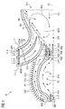
- FIG one shows a longitudinal cross section through a burner B according to the invention.
- the burner B comprises a pilot combustor PC and a main combustor MC.
- the pilot combustor PC supplies a flow of heat H and radicals R into a main combustion room MCR of the main combustor MC.
- the main combustor MC comprises a burner housing BH enclosing the main combustion room MCR and the supply of air A and fuel F into the main combustor room and further in a non depicted manner the burner housing BH also encloses the pilot combustor PC.
- the pilot combustor PC discharges the heat H and the radicals R into said main combustion room MCR through a throat THR.
- a burner axis CX is defined by a center line extending in the direction of the resulting main flow through said throat THR.
- the supply of air A and fuel F into the main combustion room MCR is provided by two annular channels, a first channel CH1 and a second channel CH2.
- the first channel CH1 is divided from the second channel CH2 by a splitter plate SP.
- Both openings of said channels CH1, CH2 into the main combustion room MCR have an annular shape, which is coaxial to the burner axis CX. Further, the openings of the channel CH1, CH2 succeed to each other in a staggered manner with regard to the burner axis CX, wherein the first channel CH1 opens upstream into the main combustion room with regard to the second channel CH2 and downstream with regard to said throat THR of the pilot combustor PC.
- a main swirler MSW provided in the first channel CH1 and the second channel CH2 gives the mixture of fuel F and air A a defined swirl influencing significantly the flow distribution in the main combustion room MCR.
- the shape of the main combustion room MCR, the flow distribution of the mixture of fuel F and air A entering the main combustion room through channel CH1 and channel CH2 and the radicals R discharged into the main combustion room MCR by the pilot combustor PC establish a recirculation zone RCZ in the main combustion room MCR in training a portion or deburned combustion gas CG, which might contain unburned hydro carbons from an exhaust EXH of the burner housing BH.
- the velocity distribution in main combustion room MCR further establishes a stagnation point STP downstream said throat THR and on the burner axis CX. While in the centre of the recirculation zone RCZ the mixture is relatively lean and the temperature is high, the mixture is enriched at the openings of said first channel CH1 and said second channel CH2 into the main combustion room MCR, where a flame front FF is most likely to establish.
- a main fuel injection MFI is provided in the first channel CH1 and the second channel CH2 injecting the major portion of fuel F to be burned in the burner B.
- the pilot combustion PC is provided with a supply module SM supplying fuel F and Air A into a pilot combustion room PCR.
- the amount of fuel F and air A to be supplied into the pilot combustion room PCS is below 15% of the total mass flow of fuel F and air A into the burner B.
- the combustion in the pilot combustor room PCR is richer than in the main combustion room MCR, which results in a significantly higher temperature.
- the pilot combustion room PCR is equipped with an ignition module IGN, which ignites the combustion in the pilot combustor PC.
- the pilot combustor PC has its own pilot combustor housing PCH, which is cooled by a cooling air flow CAF.
- the cooling air flow CAF passes through a preferated?
- a surrounding cooling cavity CCV channeling the cooling air flow CAF on the pilot combustor housing PCH passes a separate swirler SWP upstream entering the main combustion room MCR.
- the fuel F and air A entering the pilot combustion room PCR through the supply module SM is premixed.
- the throat THR is provided with flow guiding protrusions PRO to give the flow entering the main combustion room MCR a defined circumferential velocity distribution.
- a further fuel injections happens in the throat THR trough side walls of the protrusions PRO, which are provided with nozzles NOZ ejecting a jet of fuel F into the flow of heat H and radicals R discharging into the main combustion room.
- the nozzles NOZ connect the flow channel of the throat THR with an inner cavity CV provided in the protrusion PRO, which is supplied with fuel F through channels provided in the adjacent wings of said swirler SWP.
- the wings of the swirler SWP receive the fuel F from channels through a side wall of said first channel CH1.
- Figure 2 shows a three dimensional picture of a throat THR according to the invention.
- the throat THR is provided with basically round shape extending coaxially along said burner axis CX.
- the same throat THR is also depicted in figure 3 shown in a different perspective.
- Protrusions PRO are provided with a symmetry, which results in a cross shape CSH of the opening of the throat THR.
- An inner surface IS is provided with convex KS and concave KK portions.
- the radial cross section depicted in figure 3 comprises concave KK and convex KS portions of the inner surface IS of the throat THR.
- the protrusions PRO and the recesses REC in figure 3 are basically parallel to the burner axis CX.
- FIG. 4 shows a preferred embodiment of the throat THR according to the invention in a three-dimensional simplified depiction.
- Said protrusions PRO and recesses REC follow basically a helical path arranged coaxially around a burner axis CX.
- the swirl of the flow given by this helical shape is counterwise with regard to the swirl in the main combustion room MCR.
- Figure 5 shows a throat THR provided with fuel injection by means of nozzles NOZ provided on flanks respectively side walls of the protrusions PRO respectively recesses REC.
- the nozzles NOZ connect an inner cavity CF inside said protrusions PRO, which is supplied with pressurized fuel F to be injected into the flow through nozzles provided in the throat THR.
- the inner cavity CV receives the flow of fuel F through a non depicted channel provided in swirler wings of the pilots swirler SWP.
Landscapes
- Engineering & Computer Science (AREA)
- Chemical & Material Sciences (AREA)
- Combustion & Propulsion (AREA)
- Mechanical Engineering (AREA)
- General Engineering & Computer Science (AREA)
Priority Applications (5)
| Application Number | Priority Date | Filing Date | Title |
|---|---|---|---|
| EP10184134A EP2436977A1 (fr) | 2010-09-30 | 2010-09-30 | Brûleur pour turbine à gaz |
| EP11766937.4A EP2606280A1 (fr) | 2010-09-30 | 2011-09-27 | Brûleur pour une turbine à gaz |
| PCT/EP2011/066747 WO2012041839A1 (fr) | 2010-09-30 | 2011-09-27 | Brûleur pour une turbine à gaz |
| CN201180047759XA CN103140714A (zh) | 2010-09-30 | 2011-09-27 | 用于燃气轮机的燃烧器 |
| US13/876,594 US20140026579A1 (en) | 2010-09-30 | 2011-09-27 | Burner for a gas turbine |
Applications Claiming Priority (1)
| Application Number | Priority Date | Filing Date | Title |
|---|---|---|---|
| EP10184134A EP2436977A1 (fr) | 2010-09-30 | 2010-09-30 | Brûleur pour turbine à gaz |
Publications (1)
| Publication Number | Publication Date |
|---|---|
| EP2436977A1 true EP2436977A1 (fr) | 2012-04-04 |
Family
ID=43567780
Family Applications (2)
| Application Number | Title | Priority Date | Filing Date |
|---|---|---|---|
| EP10184134A Withdrawn EP2436977A1 (fr) | 2010-09-30 | 2010-09-30 | Brûleur pour turbine à gaz |
| EP11766937.4A Withdrawn EP2606280A1 (fr) | 2010-09-30 | 2011-09-27 | Brûleur pour une turbine à gaz |
Family Applications After (1)
| Application Number | Title | Priority Date | Filing Date |
|---|---|---|---|
| EP11766937.4A Withdrawn EP2606280A1 (fr) | 2010-09-30 | 2011-09-27 | Brûleur pour une turbine à gaz |
Country Status (4)
| Country | Link |
|---|---|
| US (1) | US20140026579A1 (fr) |
| EP (2) | EP2436977A1 (fr) |
| CN (1) | CN103140714A (fr) |
| WO (1) | WO2012041839A1 (fr) |
Cited By (1)
| Publication number | Priority date | Publication date | Assignee | Title |
|---|---|---|---|---|
| EP2767696A1 (fr) * | 2013-02-15 | 2014-08-20 | Siemens Aktiengesellschaft | Ensemble comprenant une turbine à gaz |
Families Citing this family (13)
| Publication number | Priority date | Publication date | Assignee | Title |
|---|---|---|---|---|
| US10463823B2 (en) * | 2014-03-10 | 2019-11-05 | Morpheus Medical Solutions, LLC | Facial mask and method of making |
| TWI565396B (zh) * | 2015-11-04 | 2017-01-01 | 川湖科技股份有限公司 | 滑軌總成 |
| US10641176B2 (en) * | 2016-03-25 | 2020-05-05 | General Electric Company | Combustion system with panel fuel injector |
| US20180355795A1 (en) * | 2017-06-09 | 2018-12-13 | General Electric Company | Rotating detonation combustor with fluid diode structure |
| US11994292B2 (en) | 2020-08-31 | 2024-05-28 | General Electric Company | Impingement cooling apparatus for turbomachine |
| US11614233B2 (en) | 2020-08-31 | 2023-03-28 | General Electric Company | Impingement panel support structure and method of manufacture |
| US11460191B2 (en) | 2020-08-31 | 2022-10-04 | General Electric Company | Cooling insert for a turbomachine |
| US11994293B2 (en) | 2020-08-31 | 2024-05-28 | General Electric Company | Impingement cooling apparatus support structure and method of manufacture |
| US11371702B2 (en) | 2020-08-31 | 2022-06-28 | General Electric Company | Impingement panel for a turbomachine |
| US11255545B1 (en) | 2020-10-26 | 2022-02-22 | General Electric Company | Integrated combustion nozzle having a unified head end |
| JP7635081B2 (ja) * | 2021-06-14 | 2025-02-25 | 東芝エネルギーシステムズ株式会社 | トーチ点火機構付きバーナおよびその運転方法 |
| CN115234942B (zh) * | 2022-06-28 | 2023-07-28 | 北京航空航天大学 | 利用文氏管喷射燃料的燃烧室 |
| US11767766B1 (en) | 2022-07-29 | 2023-09-26 | General Electric Company | Turbomachine airfoil having impingement cooling passages |
Citations (4)
| Publication number | Priority date | Publication date | Assignee | Title |
|---|---|---|---|---|
| US3851466A (en) * | 1973-04-12 | 1974-12-03 | Gen Motors Corp | Combustion apparatus |
| US20050100846A1 (en) * | 2002-12-04 | 2005-05-12 | Ephraim Gutmark | Burner |
| EP1975506A1 (fr) * | 2007-03-30 | 2008-10-01 | Siemens Aktiengesellschaft | Pré-chambre de combustion |
| WO2009121777A1 (fr) | 2008-04-01 | 2009-10-08 | Siemens Aktiengesellschaft | Brûleur |
Family Cites Families (1)
| Publication number | Priority date | Publication date | Assignee | Title |
|---|---|---|---|---|
| DE19520291A1 (de) * | 1995-06-02 | 1996-12-05 | Abb Management Ag | Brennkammer |
-
2010
- 2010-09-30 EP EP10184134A patent/EP2436977A1/fr not_active Withdrawn
-
2011
- 2011-09-27 CN CN201180047759XA patent/CN103140714A/zh active Pending
- 2011-09-27 US US13/876,594 patent/US20140026579A1/en not_active Abandoned
- 2011-09-27 EP EP11766937.4A patent/EP2606280A1/fr not_active Withdrawn
- 2011-09-27 WO PCT/EP2011/066747 patent/WO2012041839A1/fr not_active Ceased
Patent Citations (4)
| Publication number | Priority date | Publication date | Assignee | Title |
|---|---|---|---|---|
| US3851466A (en) * | 1973-04-12 | 1974-12-03 | Gen Motors Corp | Combustion apparatus |
| US20050100846A1 (en) * | 2002-12-04 | 2005-05-12 | Ephraim Gutmark | Burner |
| EP1975506A1 (fr) * | 2007-03-30 | 2008-10-01 | Siemens Aktiengesellschaft | Pré-chambre de combustion |
| WO2009121777A1 (fr) | 2008-04-01 | 2009-10-08 | Siemens Aktiengesellschaft | Brûleur |
Cited By (3)
| Publication number | Priority date | Publication date | Assignee | Title |
|---|---|---|---|---|
| EP2767696A1 (fr) * | 2013-02-15 | 2014-08-20 | Siemens Aktiengesellschaft | Ensemble comprenant une turbine à gaz |
| WO2014124777A1 (fr) * | 2013-02-15 | 2014-08-21 | Siemens Aktiengesellschaft | Ensemble comprenant une turbine à gaz |
| US9909493B2 (en) | 2013-02-15 | 2018-03-06 | Siemens Aktiengesellschaft | Assembly having a gas turbine engine and a preheating arrangement |
Also Published As
| Publication number | Publication date |
|---|---|
| EP2606280A1 (fr) | 2013-06-26 |
| WO2012041839A1 (fr) | 2012-04-05 |
| CN103140714A (zh) | 2013-06-05 |
| US20140026579A1 (en) | 2014-01-30 |
Similar Documents
| Publication | Publication Date | Title |
|---|---|---|
| EP2436977A1 (fr) | Brûleur pour turbine à gaz | |
| EP2815184B1 (fr) | Brûleur | |
| EP0870989B1 (fr) | Disposition d'injection de carburant pour une chambre de combustion de turbine à gaz | |
| US20140096502A1 (en) | Burner for a gas turbine | |
| US7891190B2 (en) | Combustion chamber of a turbomachine | |
| US6834505B2 (en) | Hybrid swirler | |
| US8726668B2 (en) | Fuel atomization dual orifice fuel nozzle | |
| RU2429417C2 (ru) | Многорежимный топливный инжектор, камера сгорания, а также реактивный двигатель | |
| US8387391B2 (en) | Aerodynamically enhanced fuel nozzle | |
| KR101202936B1 (ko) | 가스 터빈의 연소기 | |
| US20090320484A1 (en) | Methods and systems to facilitate reducing flashback/flame holding in combustion systems | |
| US20100263382A1 (en) | Dual orifice pilot fuel injector | |
| US20140182294A1 (en) | Gas turbine combustor | |
| RU2439430C1 (ru) | Форсуночный модуль камеры сгорания гтд | |
| KR20150020135A (ko) | 버너 장치 및 버너 장치를 작동하기 위한 방법 | |
| CN103776060A (zh) | 再热喷燃器布置 | |
| RU2309329C2 (ru) | Вспенивающая аэродинамическая система инжектирования топливовоздушной смеси в камеру сгорания турбомашины, камера сгорания турбомашины и турбомашина | |
| RU2645801C2 (ru) | Система впрыска топлива для камеры сгорания турбомашины, содержащей кольцевую стенку с сужающимся внутренним профилем | |
| JPH08240129A (ja) | ガスタービンエンジン用燃焼器 | |
| US11846425B2 (en) | Dual fuel gas turbine engine pilot nozzles | |
| RU2439435C1 (ru) | Топливовоздушный модуль фронтового устройства камеры сгорания гтд | |
| JP3192055B2 (ja) | ガスタービン燃焼器 | |
| RU2264584C2 (ru) | Топливовоздушная горелка камеры сгорания газотурбинного двигателя | |
| EP1994334B1 (fr) | Chambre de combustion et méthode d'utilisation d'une chambre de combustion |
Legal Events
| Date | Code | Title | Description |
|---|---|---|---|
| PUAI | Public reference made under article 153(3) epc to a published international application that has entered the european phase |
Free format text: ORIGINAL CODE: 0009012 |
|
| AK | Designated contracting states |
Kind code of ref document: A1 Designated state(s): AL AT BE BG CH CY CZ DE DK EE ES FI FR GB GR HR HU IE IS IT LI LT LU LV MC MK MT NL NO PL PT RO SE SI SK SM TR |
|
| AX | Request for extension of the european patent |
Extension state: BA ME RS |
|
| RAP1 | Party data changed (applicant data changed or rights of an application transferred) |
Owner name: SIEMENS AKTIENGESELLSCHAFT |
|
| STAA | Information on the status of an ep patent application or granted ep patent |
Free format text: STATUS: THE APPLICATION IS DEEMED TO BE WITHDRAWN |
|
| 18D | Application deemed to be withdrawn |
Effective date: 20121005 |