EP2436992B1 - Dispositif de stockage pour un système de chauffage - Google Patents
Dispositif de stockage pour un système de chauffage Download PDFInfo
- Publication number
- EP2436992B1 EP2436992B1 EP11182657.4A EP11182657A EP2436992B1 EP 2436992 B1 EP2436992 B1 EP 2436992B1 EP 11182657 A EP11182657 A EP 11182657A EP 2436992 B1 EP2436992 B1 EP 2436992B1
- Authority
- EP
- European Patent Office
- Prior art keywords
- container
- storage medium
- condensation
- heat energy
- storage device
- Prior art date
- Legal status (The legal status is an assumption and is not a legal conclusion. Google has not performed a legal analysis and makes no representation as to the accuracy of the status listed.)
- Not-in-force
Links
- 238000010438 heat treatment Methods 0.000 title claims description 29
- 230000005494 condensation Effects 0.000 claims description 99
- 238000009833 condensation Methods 0.000 claims description 98
- 238000001816 cooling Methods 0.000 claims description 42
- 238000000034 method Methods 0.000 claims description 17
- 239000004449 solid propellant Substances 0.000 claims description 8
- 230000001105 regulatory effect Effects 0.000 claims description 2
- 238000009834 vaporization Methods 0.000 claims description 2
- 230000008016 vaporization Effects 0.000 claims description 2
- 238000007599 discharging Methods 0.000 claims 2
- 238000009434 installation Methods 0.000 claims 1
- 238000001704 evaporation Methods 0.000 description 15
- 230000006870 function Effects 0.000 description 11
- 230000005855 radiation Effects 0.000 description 10
- 230000008020 evaporation Effects 0.000 description 8
- 239000012528 membrane Substances 0.000 description 6
- 238000009413 insulation Methods 0.000 description 5
- XLYOFNOQVPJJNP-UHFFFAOYSA-N water Substances O XLYOFNOQVPJJNP-UHFFFAOYSA-N 0.000 description 5
- 238000007667 floating Methods 0.000 description 4
- 239000007788 liquid Substances 0.000 description 3
- 230000032258 transport Effects 0.000 description 3
- 239000000571 coke Substances 0.000 description 2
- 230000000694 effects Effects 0.000 description 2
- 230000002349 favourable effect Effects 0.000 description 2
- 230000005484 gravity Effects 0.000 description 2
- 238000004519 manufacturing process Methods 0.000 description 2
- 238000005192 partition Methods 0.000 description 2
- 239000002244 precipitate Substances 0.000 description 2
- 230000002035 prolonged effect Effects 0.000 description 2
- 238000007789 sealing Methods 0.000 description 2
- 238000000926 separation method Methods 0.000 description 2
- 239000002028 Biomass Substances 0.000 description 1
- 238000010521 absorption reaction Methods 0.000 description 1
- 230000002411 adverse Effects 0.000 description 1
- 230000001174 ascending effect Effects 0.000 description 1
- 238000001311 chemical methods and process Methods 0.000 description 1
- 238000006243 chemical reaction Methods 0.000 description 1
- 230000003247 decreasing effect Effects 0.000 description 1
- 230000007547 defect Effects 0.000 description 1
- 230000005611 electricity Effects 0.000 description 1
- 239000000284 extract Substances 0.000 description 1
- 238000010304 firing Methods 0.000 description 1
- 239000000446 fuel Substances 0.000 description 1
- 230000017525 heat dissipation Effects 0.000 description 1
- 238000005338 heat storage Methods 0.000 description 1
- 230000010354 integration Effects 0.000 description 1
- 239000000463 material Substances 0.000 description 1
- 230000002085 persistent effect Effects 0.000 description 1
- 238000005057 refrigeration Methods 0.000 description 1
- 230000000630 rising effect Effects 0.000 description 1
- 239000000126 substance Substances 0.000 description 1
- 230000002459 sustained effect Effects 0.000 description 1
- 230000005514 two-phase flow Effects 0.000 description 1
- 238000009423 ventilation Methods 0.000 description 1
- 239000002918 waste heat Substances 0.000 description 1
Images

Classifications
-
- F—MECHANICAL ENGINEERING; LIGHTING; HEATING; WEAPONS; BLASTING
- F24—HEATING; RANGES; VENTILATING
- F24D—DOMESTIC- OR SPACE-HEATING SYSTEMS, e.g. CENTRAL HEATING SYSTEMS; DOMESTIC HOT-WATER SUPPLY SYSTEMS; ELEMENTS OR COMPONENTS THEREFOR
- F24D11/00—Central heating systems using heat accumulated in storage masses
- F24D11/002—Central heating systems using heat accumulated in storage masses water heating system
- F24D11/003—Central heating systems using heat accumulated in storage masses water heating system combined with solar energy
-
- F—MECHANICAL ENGINEERING; LIGHTING; HEATING; WEAPONS; BLASTING
- F24—HEATING; RANGES; VENTILATING
- F24S—SOLAR HEAT COLLECTORS; SOLAR HEAT SYSTEMS
- F24S40/00—Safety or protection arrangements of solar heat collectors; Preventing malfunction of solar heat collectors
- F24S40/50—Preventing overheating or overpressure
- F24S40/53—Preventing overheating or overpressure by venting solar heat collector enclosures
-
- F—MECHANICAL ENGINEERING; LIGHTING; HEATING; WEAPONS; BLASTING
- F24—HEATING; RANGES; VENTILATING
- F24S—SOLAR HEAT COLLECTORS; SOLAR HEAT SYSTEMS
- F24S40/00—Safety or protection arrangements of solar heat collectors; Preventing malfunction of solar heat collectors
- F24S40/50—Preventing overheating or overpressure
- F24S40/55—Arrangements for cooling, e.g. by using external heat dissipating means or internal cooling circuits
-
- F—MECHANICAL ENGINEERING; LIGHTING; HEATING; WEAPONS; BLASTING
- F24—HEATING; RANGES; VENTILATING
- F24S—SOLAR HEAT COLLECTORS; SOLAR HEAT SYSTEMS
- F24S60/00—Arrangements for storing heat collected by solar heat collectors
-
- F—MECHANICAL ENGINEERING; LIGHTING; HEATING; WEAPONS; BLASTING
- F24—HEATING; RANGES; VENTILATING
- F24S—SOLAR HEAT COLLECTORS; SOLAR HEAT SYSTEMS
- F24S60/00—Arrangements for storing heat collected by solar heat collectors
- F24S60/10—Arrangements for storing heat collected by solar heat collectors using latent heat
-
- F—MECHANICAL ENGINEERING; LIGHTING; HEATING; WEAPONS; BLASTING
- F24—HEATING; RANGES; VENTILATING
- F24S—SOLAR HEAT COLLECTORS; SOLAR HEAT SYSTEMS
- F24S60/00—Arrangements for storing heat collected by solar heat collectors
- F24S60/30—Arrangements for storing heat collected by solar heat collectors storing heat in liquids
-
- F—MECHANICAL ENGINEERING; LIGHTING; HEATING; WEAPONS; BLASTING
- F28—HEAT EXCHANGE IN GENERAL
- F28D—HEAT-EXCHANGE APPARATUS, NOT PROVIDED FOR IN ANOTHER SUBCLASS, IN WHICH THE HEAT-EXCHANGE MEDIA DO NOT COME INTO DIRECT CONTACT
- F28D15/00—Heat-exchange apparatus with the intermediate heat-transfer medium in closed tubes passing into or through the conduit walls ; Heat-exchange apparatus employing intermediate heat-transfer medium or bodies
- F28D15/02—Heat-exchange apparatus with the intermediate heat-transfer medium in closed tubes passing into or through the conduit walls ; Heat-exchange apparatus employing intermediate heat-transfer medium or bodies in which the medium condenses and evaporates, e.g. heat pipes
-
- F—MECHANICAL ENGINEERING; LIGHTING; HEATING; WEAPONS; BLASTING
- F28—HEAT EXCHANGE IN GENERAL
- F28D—HEAT-EXCHANGE APPARATUS, NOT PROVIDED FOR IN ANOTHER SUBCLASS, IN WHICH THE HEAT-EXCHANGE MEDIA DO NOT COME INTO DIRECT CONTACT
- F28D20/00—Heat storage plants or apparatus in general; Regenerative heat-exchange apparatus not covered by groups F28D17/00 or F28D19/00
- F28D20/02—Heat storage plants or apparatus in general; Regenerative heat-exchange apparatus not covered by groups F28D17/00 or F28D19/00 using latent heat
- F28D20/028—Control arrangements therefor
-
- F—MECHANICAL ENGINEERING; LIGHTING; HEATING; WEAPONS; BLASTING
- F24—HEATING; RANGES; VENTILATING
- F24D—DOMESTIC- OR SPACE-HEATING SYSTEMS, e.g. CENTRAL HEATING SYSTEMS; DOMESTIC HOT-WATER SUPPLY SYSTEMS; ELEMENTS OR COMPONENTS THEREFOR
- F24D2200/00—Heat sources or energy sources
- F24D2200/10—Fire place
-
- F—MECHANICAL ENGINEERING; LIGHTING; HEATING; WEAPONS; BLASTING
- F24—HEATING; RANGES; VENTILATING
- F24D—DOMESTIC- OR SPACE-HEATING SYSTEMS, e.g. CENTRAL HEATING SYSTEMS; DOMESTIC HOT-WATER SUPPLY SYSTEMS; ELEMENTS OR COMPONENTS THEREFOR
- F24D2200/00—Heat sources or energy sources
- F24D2200/14—Solar energy
-
- F—MECHANICAL ENGINEERING; LIGHTING; HEATING; WEAPONS; BLASTING
- F24—HEATING; RANGES; VENTILATING
- F24D—DOMESTIC- OR SPACE-HEATING SYSTEMS, e.g. CENTRAL HEATING SYSTEMS; DOMESTIC HOT-WATER SUPPLY SYSTEMS; ELEMENTS OR COMPONENTS THEREFOR
- F24D2220/00—Components of central heating installations excluding heat sources
- F24D2220/10—Heat storage materials, e.g. phase change materials or static water enclosed in a space
-
- F—MECHANICAL ENGINEERING; LIGHTING; HEATING; WEAPONS; BLASTING
- F28—HEAT EXCHANGE IN GENERAL
- F28D—HEAT-EXCHANGE APPARATUS, NOT PROVIDED FOR IN ANOTHER SUBCLASS, IN WHICH THE HEAT-EXCHANGE MEDIA DO NOT COME INTO DIRECT CONTACT
- F28D20/00—Heat storage plants or apparatus in general; Regenerative heat-exchange apparatus not covered by groups F28D17/00 or F28D19/00
- F28D2020/0065—Details, e.g. particular heat storage tanks, auxiliary members within tanks
-
- Y—GENERAL TAGGING OF NEW TECHNOLOGICAL DEVELOPMENTS; GENERAL TAGGING OF CROSS-SECTIONAL TECHNOLOGIES SPANNING OVER SEVERAL SECTIONS OF THE IPC; TECHNICAL SUBJECTS COVERED BY FORMER USPC CROSS-REFERENCE ART COLLECTIONS [XRACs] AND DIGESTS
- Y02—TECHNOLOGIES OR APPLICATIONS FOR MITIGATION OR ADAPTATION AGAINST CLIMATE CHANGE
- Y02B—CLIMATE CHANGE MITIGATION TECHNOLOGIES RELATED TO BUILDINGS, e.g. HOUSING, HOUSE APPLIANCES OR RELATED END-USER APPLICATIONS
- Y02B10/00—Integration of renewable energy sources in buildings
- Y02B10/20—Solar thermal
-
- Y—GENERAL TAGGING OF NEW TECHNOLOGICAL DEVELOPMENTS; GENERAL TAGGING OF CROSS-SECTIONAL TECHNOLOGIES SPANNING OVER SEVERAL SECTIONS OF THE IPC; TECHNICAL SUBJECTS COVERED BY FORMER USPC CROSS-REFERENCE ART COLLECTIONS [XRACs] AND DIGESTS
- Y02—TECHNOLOGIES OR APPLICATIONS FOR MITIGATION OR ADAPTATION AGAINST CLIMATE CHANGE
- Y02B—CLIMATE CHANGE MITIGATION TECHNOLOGIES RELATED TO BUILDINGS, e.g. HOUSING, HOUSE APPLIANCES OR RELATED END-USER APPLICATIONS
- Y02B10/00—Integration of renewable energy sources in buildings
- Y02B10/70—Hybrid systems, e.g. uninterruptible or back-up power supplies integrating renewable energies
-
- Y—GENERAL TAGGING OF NEW TECHNOLOGICAL DEVELOPMENTS; GENERAL TAGGING OF CROSS-SECTIONAL TECHNOLOGIES SPANNING OVER SEVERAL SECTIONS OF THE IPC; TECHNICAL SUBJECTS COVERED BY FORMER USPC CROSS-REFERENCE ART COLLECTIONS [XRACs] AND DIGESTS
- Y02—TECHNOLOGIES OR APPLICATIONS FOR MITIGATION OR ADAPTATION AGAINST CLIMATE CHANGE
- Y02E—REDUCTION OF GREENHOUSE GAS [GHG] EMISSIONS, RELATED TO ENERGY GENERATION, TRANSMISSION OR DISTRIBUTION
- Y02E10/00—Energy generation through renewable energy sources
- Y02E10/40—Solar thermal energy, e.g. solar towers
-
- Y—GENERAL TAGGING OF NEW TECHNOLOGICAL DEVELOPMENTS; GENERAL TAGGING OF CROSS-SECTIONAL TECHNOLOGIES SPANNING OVER SEVERAL SECTIONS OF THE IPC; TECHNICAL SUBJECTS COVERED BY FORMER USPC CROSS-REFERENCE ART COLLECTIONS [XRACs] AND DIGESTS
- Y02—TECHNOLOGIES OR APPLICATIONS FOR MITIGATION OR ADAPTATION AGAINST CLIMATE CHANGE
- Y02E—REDUCTION OF GREENHOUSE GAS [GHG] EMISSIONS, RELATED TO ENERGY GENERATION, TRANSMISSION OR DISTRIBUTION
- Y02E60/00—Enabling technologies; Technologies with a potential or indirect contribution to GHG emissions mitigation
- Y02E60/14—Thermal energy storage
-
- Y—GENERAL TAGGING OF NEW TECHNOLOGICAL DEVELOPMENTS; GENERAL TAGGING OF CROSS-SECTIONAL TECHNOLOGIES SPANNING OVER SEVERAL SECTIONS OF THE IPC; TECHNICAL SUBJECTS COVERED BY FORMER USPC CROSS-REFERENCE ART COLLECTIONS [XRACs] AND DIGESTS
- Y02—TECHNOLOGIES OR APPLICATIONS FOR MITIGATION OR ADAPTATION AGAINST CLIMATE CHANGE
- Y02E—REDUCTION OF GREENHOUSE GAS [GHG] EMISSIONS, RELATED TO ENERGY GENERATION, TRANSMISSION OR DISTRIBUTION
- Y02E70/00—Other energy conversion or management systems reducing GHG emissions
- Y02E70/30—Systems combining energy storage with energy generation of non-fossil origin
Definitions
- the invention relates to a storage device for storing heat energy in a heating system according to the preamble of claim 1 ..
- heating systems consisting of a storage device for storing heat energy, with a container in which a storage medium and a condensation device is known, in which the condensation means for condensing of the container evaporating storage medium has a condensation surface which is cooled by a cooling device.
- JP 59-134488 discloses a method for dissipating heat energy from a storage device for storing heat energy in a heating system according to the preamble of claim 1 and a storage device for storing heat energy in a heating system according to the preamble of claim 5.
- heating systems for example solar thermal systems (solar systems) usually used for hot water production with high solar coverage, but also for the space heating support.
- the invention has for its object to avoid these and other disadvantages of the prior art and to develop a method that absorbs excess energy in a heating system and selectively dissipates to prevent the occurrence of stagnation in a solar thermal system.
- the method should be reliably feasible and inexpensive to implement by simple means. It should also increase the effectiveness of the heating system and extend its life.
- the invention is further based on the object to provide a storage device for storing heat energy, with the occurrence of stagnation is effectively prevented in a solar thermal system.
- the storage device should be constructed inexpensively by simple means and be easy to handle. It should also increase the effectiveness of the heating system and extend its life.
- the heat energy is first stored.
- a high storage temperature phase that reaches or exceeds the evaporative temperature limit of the storage medium
- the storage medium within the container begins to vaporize, i.e., evaporate.
- the heat of vaporization of the storage medium is used to perform a phase change.
- the vaporous storage medium comes into contact with the container, it releases its recovered energy to the container, which in turn forwards the absorbed heat energy to the environment, so that excess energy is deliberately removed from the heating system.
- the storage medium is in this case a means of transport for excess heat energy, which would otherwise lead to stagnation or other problems within the heating system, especially if the storage capacity of the storage medium is exhausted and the connected consumers remove heat energy from the storage device. The entire thermal load of the solar circuit is reduced. Damage to the system is effectively avoided.
- the inventive method can be implemented cost-effectively and reliably, for example, with a pressureless storage container, wherein the storage container is filled with a liquid storage medium, preferably water, and takes on a further function, namely the transfer of heat energy from the vapor storage medium and the release of the absorbed heat energy the environment.
- a liquid storage medium preferably water
- the vaporous storage medium releases its heat energy to the container by means of condensation.
- the vaporous storage medium is expediently guided along an inner surface of the container.
- the condensation removes heat energy from the steam within the container in a simple manner. This in turn is discharged via the container to the outside, so that the heating system, if necessary, energy is withdrawn.
- the storage medium can continue to absorb energy at any time if the heat transfer medium in the solar circuit continues to enter energy into the storage due to persistent solar radiation. A lengthy cooling of the system is not required. This is constantly in a kind of stand-by mode.
- the invention further provides that the vaporous storage medium is returned to the container after the heat energy has been released. This preserves the storage medium; it does not have to be refilled.
- the container In order to be able to control the delivery of heat energy from the container to the environment in a targeted manner, the container is passively or actively cooled. In the case of passive cooling, the system is completely without auxiliary power, which further has a favorable effect on the operating costs. Furthermore, the cooling capacity of the heat accumulator and thus its effectiveness is further increased by the cooling.
- a further solution according to the invention for which independent protection is claimed, relates to a storage device for storing heat energy in a solar thermal system, with a container in which a storage medium is stored, and with a condensation device arranged above the storage medium, the condensation device for condensing in the container evaporating storage medium has a condensation surface which is cooled by means of a cooling device.
- a storage medium for which a storage medium is stored
- a condensation device for condensing in the container evaporating storage medium has a condensation surface which is cooled by means of a cooling device.
- an intermediate wall (26) is mounted, wherein the intermediate wall (26) at a distance from the condensation surface (10) of the container (21) is arranged.
- the condensation device integrated in the storage device it is possible to still absorb heat energy, which is generated by the solar thermal system and introduced into the storage medium via a heat carrier circulating in a solar circuit, when the storage capacity of the storage medium is exhausted and the connected consumers remove the storage device no heat energy.
- the condensation device extracts heat energy from the storage medium stored in the container when required and releases it to the environment via the cooling device.
- the storage medium initially evaporates within the container.
- the resulting vapor condenses on the condensation surface, wherein the thermal energy taken over by the heat carrier is delivered to the cooling device.
- the condensate formed on the condensation surface remains in the container and returns by gravity back into the container not evaporated storage medium, so that in the overall balance no storage medium is lost.
- the heat transfer medium circulating in the solar circuit can always emit its energy to the storage medium with the aid of the storage device according to the invention. This effectively prevents the heat transfer medium from evaporating within the solar or collector circuit. Consequently, no stagnation can occur within the system, because the excess energy is released to the environment via the condensation device, which forms a kind of emergency cooling within the storage device.
- the solar thermal system can therefore no longer go into a standstill and the temperatures within the system remain within the specified limits, so that important components of the solar system, such as the collector and the pipe system, are no longer unduly burdened. The entire thermal load of the solar circuit is reduced. Damage to the system is effectively avoided.
- water is used as the storage medium, since the evaporation range of water is within the temperature range normally achievable by solar systems.
- the heat additionally taken up by the storage medium is released into the environment through targeted condensation of the steam generated in the container.
- the storage medium is a means of transport for the excess heat.
- the condensed storage medium is completely recovered after heat removal, so that replenishment of additional storage medium is not required.
- the storage device rather forms a self-contained system that can be easily retrofitted in existing solar thermal systems by an existing conventional memory is replaced by a memory device according to the invention.
- An advantageous embodiment of the invention provides that the container at least partially forms part of the condensation device. This not only creates a very cost-effective solution.
- the integration of the condensation device in the container also allows a compact design of the storage device. It is advantageous if the container has a container wall and a roof, wherein the inner surface of the container wall and / or the roof at least partially form the condensation surface.
- the roof (or depending on the size of the container - also a cover) is preferably conical or dome-shaped, ie it forms a kind of dome or Dom, in which ascending steam can collect specifically within the container.
- the invention further provides that the cooling device is arranged above the outer surface of the container wall and / or the roof of the container. This is thereby always optimally cooled, so that vapor arising within the container can precipitate and condense on the condensation surface.
- the heat energy is transferred from the steam to the container and from the container to the cooling device. The latter therefore withdraws the storage device excess heat energy, which is thus immediately able to absorb further heat energy from the heat transfer medium of the solar circuit.
- a part of the container wall can serve as a condensation surface in addition to the roof.
- the cooling device is preferably designed as passive air cooling. It expediently has a convection tower which ensures that in the region of the container wall and / or above the roof a cooling air flow is produced which cools the roof or the container wall and consequently the condensation surface of the condensation device. Separate or additional fans or pumps are not required, so that the storage device requires no external energy. Nevertheless, depending on the size of the heating system, it is also possible to provide active cooling by using a blower or a refrigeration unit in order to extract the heat energy absorbed from the container, in particular its wall or roof.
- This partition initially fulfills an insulation function. It separates the condensation zone from the evaporation zone, i. the condensation surface is thermally separated from the storage medium.
- the rising in the container of the storage device steam can always condense optimally on the condensation surface of the roof.
- the intermediate wall fulfills a guiding function in that the vaporized storage medium is directed over the condensation surface in a targeted manner.
- the intermediate wall has a collecting function: it catches the condensate dripping from the condensation surface and deliberately returns it to the storage tank so that no losses occur. There is no loss of stored heat energy, nor does the storage medium need to be refilled.
- the geometry or design of the intermediate wall preferably corresponds to the geometry and design of the container, wherein the intermediate wall is preferably arranged parallel to the container wall and / or the roof.
- the intermediate wall can be designed thermally insulating on its steam area side surface or provided with a thermal insulation, so that a direct heat transfer by heat radiation of the liquid storage medium is effectively avoided on the cooled condensation surface.
- the intermediate wall is advantageously arranged at a distance to the condensation surface of the container, wherein the distance is dimensioned such that on the one hand, the steam conducted via the condensation surface can condense unhindered and at the same time the resulting condensate can be discharged on the intermediate wall in the direction of storage medium.
- the opening can be closed by means of a valve device.
- the entry of steam into the condensation zone can be selectively controlled, i.
- opening of the valve device can be effected or prevented. Opens the valve, for example, from a certain above the surface of the storage medium prevailing vapor pressure, the steam can flow through the opening into the condensation region, wherein the intermediate wall leads the vapor along the condensation surface.
- the steam cools, condenses and is returned as condensate in the storage medium. This can absorb further heat energy from the heat transfer medium from the collector circuit in the case of sustained or increased solar radiation. With reduced solar radiation, the valve device can close the opening again, so that the energy stored in the storage medium is stored.
- the valve device comprises, for example, a spring-loaded, pressure-sensitive or screw-type valve or an elastic membrane for opening and closing the opening in the intermediate wall, which in these embodiments is fixed in the container.
- the closing or opening of the valve device can be passive in one embodiment, for example by simple reaction of the valve device to the conditions in the container interior, which are determined by the vapor pressure and / or the temperature.
- the valve device can be actively controlled, for example manually or automatically. The control is then adaptable to day and night times and / or weather conditions.
- the intermediate wall is floatingly mounted on the storage medium, wherein the intermediate wall expediently forms part of the valve device and the opening in the intermediate wall is closed by a valve body fixed inside the container. In the lowered position, the edge of the opening rests on the valve body in such a way that no steam can flow through the opening. As the vapor pressure in the steam area increases, the floating partition wall is raised and pressed in the direction of the condensation surface. As a result, the opening in the intermediate wall is released and the vaporous storage medium can flow into the condensation region.
- a further embodiment of the invention provides that the condensation surface, the container wall, the roof and / or the cooling device are provided inside and / or outside with surface-enlarging elements. This results in a larger area and thus greater heat transfer, e.g. from the condensed storage medium to the roof of the container.
- the surface-enlarging elements are advantageously designed so that the heat absorption and removal are favored.
- the storage device according to the invention with the condensation device provides a kind of emergency cooling, which - depending on the embodiment - requires no auxiliary power, increases the effectiveness of the solar system and extends the robustness and life of central components of the solar system.
- a thermal solar system with a corresponding storage device advantageously does not reach the high temperatures of a stagnation phase.
- the condenser rather a constant heat dissipation is possible and it is no longer necessary to wait until the solar system has cooled from the high temperatures of the stagnation phase, ie about 200 ° C, to the desired temperature level of about 100 ° C.
- the solar system according to the invention is advantageously very robust and durable, since the thermal load of all components of the system is significantly reduced.
- Both the method according to the invention and the storage device according to the invention can be advantageously used not only in solar thermal systems. It is also possible to use it in heating systems which use heat generators with non-controllable firing, e.g. Solid fuel boilers. These must be equipped with special temperature limiters for emergency cooling according to DIN EN 12828, e.g. thermal drainage and / or separate safety heat exchanger, which usually causes additional costs.
- Such emergency cooling is required when the intended storage facility is exhausted, but the solid fuel boiler must forcibly continue to supply heat energy due to the already charged solid fuel (e.g., log fill or coke charge).
- the storage device according to the invention also ensures that the selected heating circuit can be dimensioned significantly smaller, which is the case, for example Underfloor heating is advantageous, which is usually not suitable for high temperatures. The entire heating system can therefore be extremely cost-effective.
- the method according to the invention is advantageously used in a solar thermal system (not shown), for example in a thermal solar system, which absorbs thermal energy by means of a heat carrier and introduces it into a storage medium 32, which is stored in a container 21.
- a solar thermal system which absorbs thermal energy by means of a heat carrier and introduces it into a storage medium 32, which is stored in a container 21.
- the storage medium 32 reaches its evaporation temperature or exceeds it with further input of energy, it evaporates within the container and comes into contact with the inner surfaces of the container 21. It transmits its heat energy by condensation on the container 21, which in turn emits the absorbed heat energy to the environment.
- the steam guided over the inner surfaces of the container is then led back into the container, so that a self-contained circuit is created.
- the container is cooled passively or actively. Further, the amount of heat energy dissipated from the vapor storage medium 32 to the container 21 is controlled and / or controlled.
- a storage device 200 for carrying out the method according to the invention, is provided, which is used in the solar thermal system as a heat storage.
- the storage device 200 is integrated into the system in a manner known per se, and the solar collectors (likewise not shown) are connected via connections and pipelines.
- the heat transfer medium circulates in the solar collectors and pipelines. This takes up heat energy within the solar panels and gives them - usually via a heat exchanger - to the storage device 200, which is for this purpose filled with the storage medium 32.
- the circulation of the plant is operated by means of a pump or by buoyancy and gravity.
- Each storage device 200 has for receiving the storage medium 32, a container 21 which forms a sealed container inner region 23 with a substantially cylindrical container wall 22, a conical or dome-like roof 24 and a bottom 27.
- the storage medium 32 is, for example, water, which is located in the lower region of the container inner region 23.
- the conical roof 24 of the container 21 is formed as part of a condensation device 100. This includes, in addition to the roof 24 - which forms a condensation surface 10 with its inner surface - a arranged in the container 21 also conical or dome-like intermediate wall 26 and a cooling device 50 arranged above the roof 24.
- the intermediate wall 26 is mounted at a distance from the inner surface 10 of the roof 24, so that between the roof 24 and the intermediate wall 26, a gap is present. This is dimensioned such that in the container inner region 23 of the container 21 evaporating storage medium 32 can condense within the gap on the condensation surface 10 of the roof 24 and drain as condensate 33 on the intermediate wall 26. At this time, the evaporated storage medium 32 transfers its heat energy to the roof 24, which is cooled by the cooling device 50. So that the vapor 31 can be specifically supplied to the condensation surface 10 and passed along it, the conical or dome-shaped intermediate wall 26 forms an opening 28 in its upper region.
- the intermediate wall 26 which is made of a material of low thermal conductivity and low density, forms both a kind of baffle and a thermal separation, because it divides the upper region of the container interior region 21 into a vapor region 25, which lies below the intermediate wall 26, and a gap which between the intermediate wall 26 and the condensation surface 10 of the roof 24 forms a condensation region. It therefore represents a boundary between the condensation region and the vapor region 25.
- the intermediate wall 26 may have a thermal insulation (not shown) on the area on the steam area side. As a result, a heat transfer is prevented by radiation in the condensation region 10.
- parts of the container wall 22 can also serve as a condensation surface.
- the roof 24 of the container 21 does not necessarily have to be cone-shaped or domed. Other suitable roof or wall shapes are also possible.
- the heat energy absorbed by the roof 24 is dissipated via the cooling device 50.
- This has an air duct 51 for conducting an air flow in the upper region of the condensation device 100.
- the air duct 51 comprises above the roof 24 inlets 52, which may be formed as a circumferential gap or as discrete, distributed over the circumference openings.
- An outlet 54 leads the heated air from the roof 24 upwards.
- the inlets 52 are arranged on a horizontal lower level than the outlet 53.
- the air duct 51 acts as a convection tower in the form of a chimney or air vent with natural convection.
- the inlets 52 are still positioned above the roof 24 and thus above the condensation surface 10 of the condensation device 100.
- the air flowing through the air duct 51 thereby absorbs the heat energy absorbed by the roof 24 and transports it away through the outlet 53.
- the inflowing air cools the roof 24 from the outside. The cooling is thus on the one hand by the removal of the heat dissipated and on the other by the inflowing air flow. An additional drive or an electrically operated ventilation or cooling device is therefore not necessary.
- the condensate 33 formed and cooled on the inner wall of the roof 24 or on the condensation surface 10 is collected by the intermediate wall 26, discharged downwards and fed back to the storage medium 32 laterally in the region of the container wall 22.
- the conical roof 24 can be provided inside and / or outside with surface enlarging elements (not shown) be. These are, for example, grooves, ribs, nubs, pins or the like., Which are placed on the roof 24 or integral with this. The elements provide a larger surface area and thus greater heat transfer.
- the storage device 200 prevents the heat transfer medium in the collector circuit from evaporating due to the prolonged solar radiation and, as a result, causing stagnation within the system.
- the evaporation occurring in conventional systems in the collector circuit is in the solution according to the invention quasi shifted in the storage area, so that not the heat transfer evaporates, but the storage medium 32. This is removed by means of the condensing device 100, the excess heat energy, the energy initially on the vapor storage medium 31 is transferred to the roof 24, which is then cooled by the cooling device 50.
- the resulting waste heat either goes outdoors or it can be used for other purposes, for example to heat other processes, to generate electricity or to operate a heat engine.
- the storage medium 32 within the container 21 begins to evaporate.
- the additionally introduced energy is dissipated via the condensation device 100 or via its cooling system 50. This can be promoted if necessary by the surface enlarging elements of the roof 24.
- the intermediate wall 26 favors the condensation process, because it specifically directs the steam 31 over the condensation surface 10 of the roof 24 and forms a thermal separation to the steam region 25.
- the condensate 33 is specifically collected by the intermediate wall 26 and fed to the storage medium 32 in the edge region of the container 21, which can thereby evaporate unhindered in the middle of the container 21.
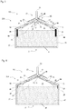
- Fig. 2 shows a schematic cross-sectional view of a storage device 200 according to the invention, which is also provided with a condensation device 100 as emergency cooling.
- condensation device 100 of the memory device 200 of Fig. 2 a valve device 40, which closes the upper opening 28 in the intermediate wall 26, so that the steam region 25 is completely separated from the condensation region between the intermediate wall 26 and the cooled condensation surface 10 of the roof 24.
- heat losses of the memory in standard operation are further reduced.
- the valve device 40 has a spring valve 41 which is mounted on a plate 42. The latter is inserted tightly into the opening 28 of the conical or dome-like intermediate wall 26.
- valve device 40 By means of the valve device 40 is carried out a targeted admission of vaporous storage medium 31 from the steam region 25 in the condensation region, so that the dissipated amount of heat is controllable, ie a condensation of the vapor 31 and thus a discharge of excess energy takes place only from a certain threshold, the over the valve device 40 or the spring valve 41 is adjustable, because the valve 41 only opens at a certain vapor pressure inside the container 21 or above the surface of the storage medium 32.
- the valve device 40 opens, the vapor 31 flows through the valve 41, wherein the intermediate wall 26 conducts the vapor 31 along the cooled condensation surface 10, so that condensate 33 is formed, which is returned to the storage medium 32 via the intermediate wall 26 and the tubes 29 , The excess energy received by the roof 24 is dissipated by the cooling device 50 to the outside.
- the embodiment of the Fig. 3 dispenses with a spring valve 41.
- the valve device 40 is rather formed by the intermediate wall 26 itself and a spherical or plate-shaped valve body 61 which can close the opening 28 in the intermediate wall 26.
- the latter is provided at the edge with floats 64 which float in the storage medium 32, wherein the weight of the intermediate wall 26 and the buoyancy of the float 64 in the storage medium 32 are dimensioned such that the intermediate wall in normal operation of the solar thermal system with the edge 62 of the opening 28 the body 61 rests tightly so that no vapor 31 can pass through the opening 28 therethrough.
- the edge 62 may be additionally provided with sealing elements.
- excess heat energy is introduced into the storage medium 32 by the heat transfer medium, it evaporates within the container 21 and the vapor pressure arising in the steam region 25 lifts the intermediate wall 26 so that it lifts off from the body 61.
- the opening 28 is released and the vapor 31 may condense on the condensation surface 10 of the roof.
- the excess energy is removed from the system by means of the cooling device 50.
- the resulting condensate 33 is collected by the intermediate wall 26 and recirculated to the edge of the storage medium 32, wherein here, if necessary, the tubes 29 of the Fig. 2 can be used.
- the threshold value of the vapor pressure at which the valve device 40 opens is also defined by the weight of the intermediate wall 26 and the buoyancy of the floating bodies 64 in the storage medium 32.
- the intermediate wall 26 forms a freely movable floating dome 60, which performs both a thermal protection function and a valve function. It is lifted by the steam 31 and lowered after its escape through the opening 28 again.
- the floating bodies 64 together with the container wall 22 guide elements, which ensure that the intermediate wall 26 is always centered within the container 21 is guided.
- the valve body 61 can serve as a guide element or forms separate guides in the container 21.
- the Fig. 3 shows the valve device 40 in the open state.
- Fig. 4 is the intermediate wall 26 rigidly inserted into the container 21 and, for example, with edge-side webs 27, between which the condensate 33 can flow into the storage medium 32, connected to the container wall 22.
- the valve device 40 is designed as an elastic valve, in particular as a membrane 70, which closes the upper opening 28 in the conical or dome-shaped intermediate wall 26 by sealing (unspecified) lips or fins of the membrane 70 sealingly on the (also unspecified ) Place the edge region of the opening 28.
- the membrane 70 closes the opening 28 by its own weight and / or its residual stress.
- the vapor 31 can not penetrate to the condensation surface 10.
- the intermediate wall 26 and the membrane 70 rather isolate the storage medium 32 with respect to the cooled roof 24. If the vapor pressure in the vapor region 25 increases, the membrane 70 is pressed from a certain vapor pressure and the vapor 31 can flow through the opening 28 and at the condensation surface 10 condense, wherein the intermediate wall 26, the steam 31 leads to the condensation surface 10 along.
- the excess energy is removed from the system by means of the cooling device 50.
- the resulting condensate 33 is collected by the intermediate wall 26 and recirculated to the edge of the storage medium 32, wherein also here, if necessary, in Fig. 2 shown pipes can be used.
- the conical or dome-like intermediate wall 26 also has several functions in this embodiment.
- the intermediate wall 26 serves as a thermal insulation element which shields the condensation surface 10 of the roof 24, which is cooled by the cooling device 50, from the generally heated storage medium 32 in the container 21. The heat losses of the memory device 200 are thereby minimized.
- the intermediate wall 26 in conjunction with the valve device 40, the vapor 31 produced in the container interior region 23 is selectively supplied to the condensation device 100 integrated in the storage device 200, which ensures that excess energy can be removed from the system.
- the intermediate wall 26 serves to return the evaporated and condensed storage medium 32, so that the system gets along without any auxiliary energy and without Frischwassernachspeisung, which further has a favorable effect on the energy balance.
- the cooling function of the storage device 200 according to the invention is used as emergency cooling in a solid fuel heating system.
- the possibility of emergency cooling is mandatory for some solid fuel systems, especially if the furnace is not quickly controllable or adaptable. This is e.g. regularly the case when the solid fuel boiler is filled with logs or coke.
- the surplus energy generated can easily be absorbed by the storage device 200 according to the invention.
- the storage medium 32 evaporates within the container 21 and then releases the excess energy to the container 21 by condensing the vapor to the condensation surfaces 10 formed in the container 21. This is cooled by the cooling device 50, so that the energy absorbed by the container 21 is dissipated immediately.
- the condensed vapor passes as a storage medium 32 back into the container 21 and can re-absorb energy there, should the solid fuel continue to provide energy.
Landscapes
- Engineering & Computer Science (AREA)
- Physics & Mathematics (AREA)
- Thermal Sciences (AREA)
- Mechanical Engineering (AREA)
- General Engineering & Computer Science (AREA)
- Life Sciences & Earth Sciences (AREA)
- Sustainable Development (AREA)
- Sustainable Energy (AREA)
- Chemical & Material Sciences (AREA)
- Combustion & Propulsion (AREA)
- Filling Or Discharging Of Gas Storage Vessels (AREA)
- Central Heating Systems (AREA)
Claims (15)
- Procédé pour évacuer de l'énergie thermique hors d'un dispositif de stockage destiné à stocker de l'énergie thermique dans un système de chauffage selon l'une quelconque des revendications 5 à 13, comprenant les étapes suivantes:a) introduire de l'énergie thermique, qui a été récupérée et/ou produite dans un système de chauffage, dans un milieu de stockage (32), qui est stocké dans un réservoir (21), dans lequel le milieu de stockage (32) atteint ou dépasse sa température d'évaporation;b) céder l'énergie thermique captée par le milieu de stockage vaporisé (32) au réservoir (21) par condensation;c) céder l'énergie thermique captée par le réservoir (21) à l'environnement,caractérisé en ce que l'on conduit le milieu de stockage vaporisé (32) le long d'une face intérieure du réservoir (21), dans lequel le milieu de stockage vaporisé est conduit méthodiquement à travers un canal d'écoulement, qui est formé entre un dispositif de condensation et une paroi intermédiaire espacée de celui-ci, et se condense sur le dispositif de condensation.
- Procédé selon la revendication 1, caractérisé en ce que l'on renvoie le milieu de stockage vaporisé (32) dans le réservoir (21) après la cession de l'énergie thermique.
- Procédé selon une des revendications 1 ou 2, caractérisé en ce que l'on refroidit le réservoir (21) de façon passive ou active.
- Procédé selon l'une quelconque des revendications 1 à 3, caractérisé en ce que l'on régule et/ou on commande la quantité de l'énergie thermique évacuée par le milieu de stockage vaporisé (32) vers le réservoir (21).
- Dispositif de stockage (200) pour le stockage d'énergie thermique dans un système de chauffage, avec un réservoir (21), dans lequel un milieu de stockage (32) est accumulé, et avec un dispositif de condensation (100), dans lequel le dispositif de condensation (100) présente pour la condensation de milieu de stockage vaporisé (32) dans le réservoir (21) une face de condensation (10), qui peut être refroidie au moyen d'un dispositif de refroidissement (50), caractérisé en ce qu'il est prévu une paroi intermédiaire (26) entre le milieu de stockage (32) et la face de condensation (10) du dispositif de condensation (100), dans lequel la paroi intermédiaire (26) est disposée à une distance de la face de condensation (10) du réservoir (21).
- Dispositif de stockage selon la revendication 5, caractérisé en ce que le réservoir (21) forme au moins partiellement une partie du dispositif de condensation (100).
- Dispositif de stockage selon la revendication 5 ou 6, caractérisé en ce que le réservoir (21) présente une paroi de réservoir (22) et un toit (24), dans lequel la face intérieure de la paroi de réservoir (22) et/ou du toit (24) forme au moins partiellement la face de condensation (10).
- Dispositif de stockage selon la revendication 7, caractérisé en ce que le dispositif de refroidissement (50) est disposé au-dessus de la face extérieure de la paroi de réservoir (22) et/ou du toit (24) du réservoir (21).
- Dispositif de stockage selon l'une quelconque des revendications 5 à 8, caractérisé en ce qu'il est prévu une ouverture (28) dans la paroi intermédiaire (26).
- Dispositif de stockage selon la revendication 9, caractérisé en ce que l'ouverture (28) peut être fermée au moyen d'un dispositif de soupape (40).
- Dispositif de stockage selon l'une quelconque des revendications 5 à 10, caractérisé en ce que la paroi intermédiaire (26) est fixée dans le réservoir (21).
- Dispositif de stockage selon l'une quelconque des revendications 5 à 11, caractérisé en ce que la paroi intermédiaire (26) est montée de façon flottante sur le milieu de stockage (32).
- Dispositif de stockage selon l'une quelconque des revendications 7 à 12, caractérisé en ce que la face de condensation (10), la paroi de réservoir (22), le toit (24) et/ou le dispositif de refroidissement (50) sont munis intérieurement et/ou extérieurement d'éléments d'agrandissement de la surface.
- Centrale thermique solaire avec un dispositif de stockage (200) selon l'une quelconque des revendications 5 à 13.
- Système de chauffage à combustible solide avec un dispositif de stockage (200) selon l'une quelconque des revendications 5 à 13.
Applications Claiming Priority (1)
| Application Number | Priority Date | Filing Date | Title |
|---|---|---|---|
| DE102010046985A DE102010046985A1 (de) | 2010-09-30 | 2010-09-30 | Speichereinrichtung für ein Heizsystem |
Publications (3)
| Publication Number | Publication Date |
|---|---|
| EP2436992A2 EP2436992A2 (fr) | 2012-04-04 |
| EP2436992A3 EP2436992A3 (fr) | 2013-01-23 |
| EP2436992B1 true EP2436992B1 (fr) | 2017-08-02 |
Family
ID=44720675
Family Applications (1)
| Application Number | Title | Priority Date | Filing Date |
|---|---|---|---|
| EP11182657.4A Not-in-force EP2436992B1 (fr) | 2010-09-30 | 2011-09-26 | Dispositif de stockage pour un système de chauffage |
Country Status (2)
| Country | Link |
|---|---|
| EP (1) | EP2436992B1 (fr) |
| DE (1) | DE102010046985A1 (fr) |
Families Citing this family (1)
| Publication number | Priority date | Publication date | Assignee | Title |
|---|---|---|---|---|
| CN111895828B (zh) * | 2020-07-17 | 2021-07-30 | 上海交通大学 | 一种具有均温结构的曲面散热水箱 |
Family Cites Families (7)
| Publication number | Priority date | Publication date | Assignee | Title |
|---|---|---|---|---|
| NL7707915A (nl) * | 1977-07-15 | 1979-01-17 | Patlico Rights Nv | Warmteopslag- en afgifte-inrichting voor warmte uit een door de zon verwarmd fluidum. |
| DE3003688C2 (de) * | 1980-02-01 | 1982-10-14 | Messerschmitt-Bölkow-Blohm GmbH, 8000 München | Wärmespeicheranlage mit einem flüssigen Wärmeträger und einem Speichertank |
| JPS5752795A (en) * | 1980-09-17 | 1982-03-29 | Toshiba Corp | Heat accumulating device |
| JPS5912289A (ja) * | 1982-07-14 | 1984-01-21 | Matsushita Electric Ind Co Ltd | 蓄熱装置 |
| JPS59134488A (ja) * | 1983-01-20 | 1984-08-02 | Agency Of Ind Science & Technol | 潜熱蓄熱装置 |
| IL104802A0 (en) * | 1992-02-20 | 1993-07-08 | Commw Scient Ind Res Org | Device and apparatus for cooling an enclosure |
| SE530959C2 (sv) * | 2006-05-29 | 2008-11-04 | Climatewell Ab Publ | Kemisk värmepump med hybridsubstans |
-
2010
- 2010-09-30 DE DE102010046985A patent/DE102010046985A1/de not_active Withdrawn
-
2011
- 2011-09-26 EP EP11182657.4A patent/EP2436992B1/fr not_active Not-in-force
Non-Patent Citations (1)
| Title |
|---|
| None * |
Also Published As
| Publication number | Publication date |
|---|---|
| DE102010046985A1 (de) | 2012-04-05 |
| EP2436992A3 (fr) | 2013-01-23 |
| EP2436992A2 (fr) | 2012-04-04 |
Similar Documents
| Publication | Publication Date | Title |
|---|---|---|
| DE102007060428B3 (de) | Verdampfungsgekühltes Brennstoffzellensystem und Verfahren zum Betreiben eines verdampfungsgekühlten Brennstoffzellensystems sowie seine Verwendung in einem Luftfahrzeug | |
| EP2423925B1 (fr) | Bassin de stockage d'éléments combustibles avec system de refroidissement | |
| EP3221655B1 (fr) | Procédé et dispositif d'introduction et d'extraction d'énergie calorifique dans un plan d'eau ou à partir d'un plan d'eau. | |
| DE102016010396B4 (de) | Solaranlage | |
| DE102008036712A1 (de) | Anordnung zur Bereitstellung von warmen Brauchwasser | |
| DE102008023566A1 (de) | Verfahren und Vorrichtung zur Wassergewinnung aus feuchter Umgebungsluft | |
| EP2361006A2 (fr) | Système de refroidissement doté d'un ventilateur pour onduleur photovoltaïque | |
| EP3027971B1 (fr) | Système de gestion de température | |
| DE102012102931A1 (de) | Wassergeführtes Solarsystem | |
| DE19604356C2 (de) | Verfahren und Vorrichtung zur Gewinnung von thermischer Energie aus solarer Energie | |
| EP2446196B1 (fr) | Procédé pour fournir de la chaleur | |
| EP2436992A2 (fr) | Dispositif de stockage pour un système de chauffage | |
| AT508315A2 (de) | Solaranlage | |
| WO2020169153A1 (fr) | Accumulateur d'énergie thermique, notamment accumulateur multizone sous la forme d'un réservoir à fond plat | |
| EP2247898B1 (fr) | Procédé de guidage de flux d'énergie thermique optimisé | |
| DE102006009112A1 (de) | Vorrichtung zur Minderung der Stagnationsbelastung in thermischen Solaranlagen | |
| EP2813782A1 (fr) | Collecteur solaire désactivable | |
| DE3015061A1 (de) | Sonnenkollektor mit ueberhitzungsschutz | |
| DE102010052103B4 (de) | Anlage zur Nutzung von Solarenergie | |
| EP2198203A2 (fr) | Absorbeur d'énergie air-solaire | |
| EP2003404A1 (fr) | Dispositif de chauffe-eau destiné au réchauffement à l'énergie solaire | |
| DE19948512C2 (de) | Meerwasser-Entsalzungsanlage und Verfahren zur Meerwasserentsalzung | |
| DE102013215927B4 (de) | Batteriemodul | |
| DE102023209361A1 (de) | Elektrolysesystem sowie Verfahren zum Betrieb eines Elektrolysesystems | |
| DE102013004269A1 (de) | Solarer Wasser-Erhitzer |
Legal Events
| Date | Code | Title | Description |
|---|---|---|---|
| PUAI | Public reference made under article 153(3) epc to a published international application that has entered the european phase |
Free format text: ORIGINAL CODE: 0009012 |
|
| AK | Designated contracting states |
Kind code of ref document: A2 Designated state(s): AL AT BE BG CH CY CZ DE DK EE ES FI FR GB GR HR HU IE IS IT LI LT LU LV MC MK MT NL NO PL PT RO RS SE SI SK SM TR |
|
| AX | Request for extension of the european patent |
Extension state: BA ME |
|
| PUAL | Search report despatched |
Free format text: ORIGINAL CODE: 0009013 |
|
| AK | Designated contracting states |
Kind code of ref document: A3 Designated state(s): AL AT BE BG CH CY CZ DE DK EE ES FI FR GB GR HR HU IE IS IT LI LT LU LV MC MK MT NL NO PL PT RO RS SE SI SK SM TR |
|
| AX | Request for extension of the european patent |
Extension state: BA ME |
|
| RIC1 | Information provided on ipc code assigned before grant |
Ipc: F28D 20/02 20060101ALI20121220BHEP Ipc: F24J 2/46 20060101ALI20121220BHEP Ipc: F24D 11/00 20060101AFI20121220BHEP Ipc: F24J 2/34 20060101ALI20121220BHEP Ipc: F28D 15/02 20060101ALI20121220BHEP |
|
| 17P | Request for examination filed |
Effective date: 20130723 |
|
| RBV | Designated contracting states (corrected) |
Designated state(s): AL AT BE BG CH CY CZ DE DK EE ES FI FR GB GR HR HU IE IS IT LI LT LU LV MC MK MT NL NO PL PT RO RS SE SI SK SM TR |
|
| GRAP | Despatch of communication of intention to grant a patent |
Free format text: ORIGINAL CODE: EPIDOSNIGR1 |
|
| RIC1 | Information provided on ipc code assigned before grant |
Ipc: F28D 20/00 20060101ALI20170207BHEP Ipc: F24J 2/46 20060101ALI20170207BHEP Ipc: F24D 11/00 20060101AFI20170207BHEP Ipc: F28D 15/02 20060101ALI20170207BHEP Ipc: F28D 20/02 20060101ALI20170207BHEP Ipc: F24J 2/34 20060101ALI20170207BHEP |
|
| INTG | Intention to grant announced |
Effective date: 20170306 |
|
| GRAS | Grant fee paid |
Free format text: ORIGINAL CODE: EPIDOSNIGR3 |
|
| GRAA | (expected) grant |
Free format text: ORIGINAL CODE: 0009210 |
|
| AK | Designated contracting states |
Kind code of ref document: B1 Designated state(s): AL AT BE BG CH CY CZ DE DK EE ES FI FR GB GR HR HU IE IS IT LI LT LU LV MC MK MT NL NO PL PT RO RS SE SI SK SM TR |
|
| REG | Reference to a national code |
Ref country code: GB Ref legal event code: FG4D Free format text: NOT ENGLISH |
|
| REG | Reference to a national code |
Ref country code: CH Ref legal event code: EP Ref country code: AT Ref legal event code: REF Ref document number: 914912 Country of ref document: AT Kind code of ref document: T Effective date: 20170815 |
|
| REG | Reference to a national code |
Ref country code: IE Ref legal event code: FG4D Free format text: LANGUAGE OF EP DOCUMENT: GERMAN |
|
| REG | Reference to a national code |
Ref country code: DE Ref legal event code: R096 Ref document number: 502011012708 Country of ref document: DE |
|
| PGFP | Annual fee paid to national office [announced via postgrant information from national office to epo] |
Ref country code: CH Payment date: 20170925 Year of fee payment: 7 |
|
| PGFP | Annual fee paid to national office [announced via postgrant information from national office to epo] |
Ref country code: AT Payment date: 20170925 Year of fee payment: 7 |
|
| REG | Reference to a national code |
Ref country code: NL Ref legal event code: MP Effective date: 20170802 |
|
| REG | Reference to a national code |
Ref country code: LT Ref legal event code: MG4D |
|
| PG25 | Lapsed in a contracting state [announced via postgrant information from national office to epo] |
Ref country code: FI Free format text: LAPSE BECAUSE OF FAILURE TO SUBMIT A TRANSLATION OF THE DESCRIPTION OR TO PAY THE FEE WITHIN THE PRESCRIBED TIME-LIMIT Effective date: 20170802 Ref country code: NL Free format text: LAPSE BECAUSE OF FAILURE TO SUBMIT A TRANSLATION OF THE DESCRIPTION OR TO PAY THE FEE WITHIN THE PRESCRIBED TIME-LIMIT Effective date: 20170802 Ref country code: LT Free format text: LAPSE BECAUSE OF FAILURE TO SUBMIT A TRANSLATION OF THE DESCRIPTION OR TO PAY THE FEE WITHIN THE PRESCRIBED TIME-LIMIT Effective date: 20170802 Ref country code: HR Free format text: LAPSE BECAUSE OF FAILURE TO SUBMIT A TRANSLATION OF THE DESCRIPTION OR TO PAY THE FEE WITHIN THE PRESCRIBED TIME-LIMIT Effective date: 20170802 Ref country code: NO Free format text: LAPSE BECAUSE OF FAILURE TO SUBMIT A TRANSLATION OF THE DESCRIPTION OR TO PAY THE FEE WITHIN THE PRESCRIBED TIME-LIMIT Effective date: 20171102 Ref country code: SE Free format text: LAPSE BECAUSE OF FAILURE TO SUBMIT A TRANSLATION OF THE DESCRIPTION OR TO PAY THE FEE WITHIN THE PRESCRIBED TIME-LIMIT Effective date: 20170802 |
|
| PGFP | Annual fee paid to national office [announced via postgrant information from national office to epo] |
Ref country code: DE Payment date: 20171128 Year of fee payment: 7 |
|
| PG25 | Lapsed in a contracting state [announced via postgrant information from national office to epo] |
Ref country code: BG Free format text: LAPSE BECAUSE OF FAILURE TO SUBMIT A TRANSLATION OF THE DESCRIPTION OR TO PAY THE FEE WITHIN THE PRESCRIBED TIME-LIMIT Effective date: 20171102 Ref country code: LV Free format text: LAPSE BECAUSE OF FAILURE TO SUBMIT A TRANSLATION OF THE DESCRIPTION OR TO PAY THE FEE WITHIN THE PRESCRIBED TIME-LIMIT Effective date: 20170802 Ref country code: ES Free format text: LAPSE BECAUSE OF FAILURE TO SUBMIT A TRANSLATION OF THE DESCRIPTION OR TO PAY THE FEE WITHIN THE PRESCRIBED TIME-LIMIT Effective date: 20170802 Ref country code: GR Free format text: LAPSE BECAUSE OF FAILURE TO SUBMIT A TRANSLATION OF THE DESCRIPTION OR TO PAY THE FEE WITHIN THE PRESCRIBED TIME-LIMIT Effective date: 20171103 Ref country code: PL Free format text: LAPSE BECAUSE OF FAILURE TO SUBMIT A TRANSLATION OF THE DESCRIPTION OR TO PAY THE FEE WITHIN THE PRESCRIBED TIME-LIMIT Effective date: 20170802 Ref country code: RS Free format text: LAPSE BECAUSE OF FAILURE TO SUBMIT A TRANSLATION OF THE DESCRIPTION OR TO PAY THE FEE WITHIN THE PRESCRIBED TIME-LIMIT Effective date: 20170802 Ref country code: IS Free format text: LAPSE BECAUSE OF FAILURE TO SUBMIT A TRANSLATION OF THE DESCRIPTION OR TO PAY THE FEE WITHIN THE PRESCRIBED TIME-LIMIT Effective date: 20171202 |
|
| PG25 | Lapsed in a contracting state [announced via postgrant information from national office to epo] |
Ref country code: RO Free format text: LAPSE BECAUSE OF FAILURE TO SUBMIT A TRANSLATION OF THE DESCRIPTION OR TO PAY THE FEE WITHIN THE PRESCRIBED TIME-LIMIT Effective date: 20170802 Ref country code: DK Free format text: LAPSE BECAUSE OF FAILURE TO SUBMIT A TRANSLATION OF THE DESCRIPTION OR TO PAY THE FEE WITHIN THE PRESCRIBED TIME-LIMIT Effective date: 20170802 Ref country code: CZ Free format text: LAPSE BECAUSE OF FAILURE TO SUBMIT A TRANSLATION OF THE DESCRIPTION OR TO PAY THE FEE WITHIN THE PRESCRIBED TIME-LIMIT Effective date: 20170802 |
|
| REG | Reference to a national code |
Ref country code: DE Ref legal event code: R097 Ref document number: 502011012708 Country of ref document: DE |
|
| PG25 | Lapsed in a contracting state [announced via postgrant information from national office to epo] |
Ref country code: SM Free format text: LAPSE BECAUSE OF FAILURE TO SUBMIT A TRANSLATION OF THE DESCRIPTION OR TO PAY THE FEE WITHIN THE PRESCRIBED TIME-LIMIT Effective date: 20170802 Ref country code: SK Free format text: LAPSE BECAUSE OF FAILURE TO SUBMIT A TRANSLATION OF THE DESCRIPTION OR TO PAY THE FEE WITHIN THE PRESCRIBED TIME-LIMIT Effective date: 20170802 Ref country code: EE Free format text: LAPSE BECAUSE OF FAILURE TO SUBMIT A TRANSLATION OF THE DESCRIPTION OR TO PAY THE FEE WITHIN THE PRESCRIBED TIME-LIMIT Effective date: 20170802 Ref country code: IT Free format text: LAPSE BECAUSE OF FAILURE TO SUBMIT A TRANSLATION OF THE DESCRIPTION OR TO PAY THE FEE WITHIN THE PRESCRIBED TIME-LIMIT Effective date: 20170802 Ref country code: MC Free format text: LAPSE BECAUSE OF FAILURE TO SUBMIT A TRANSLATION OF THE DESCRIPTION OR TO PAY THE FEE WITHIN THE PRESCRIBED TIME-LIMIT Effective date: 20170802 |
|
| PLBE | No opposition filed within time limit |
Free format text: ORIGINAL CODE: 0009261 |
|
| STAA | Information on the status of an ep patent application or granted ep patent |
Free format text: STATUS: NO OPPOSITION FILED WITHIN TIME LIMIT |
|
| REG | Reference to a national code |
Ref country code: IE Ref legal event code: MM4A |
|
| REG | Reference to a national code |
Ref country code: BE Ref legal event code: MM Effective date: 20170930 |
|
| PG25 | Lapsed in a contracting state [announced via postgrant information from national office to epo] |
Ref country code: LU Free format text: LAPSE BECAUSE OF NON-PAYMENT OF DUE FEES Effective date: 20170926 |
|
| REG | Reference to a national code |
Ref country code: FR Ref legal event code: ST Effective date: 20180531 |
|
| 26N | No opposition filed |
Effective date: 20180503 |
|
| GBPC | Gb: european patent ceased through non-payment of renewal fee |
Effective date: 20171102 |
|
| PG25 | Lapsed in a contracting state [announced via postgrant information from national office to epo] |
Ref country code: IE Free format text: LAPSE BECAUSE OF NON-PAYMENT OF DUE FEES Effective date: 20170926 |
|
| PG25 | Lapsed in a contracting state [announced via postgrant information from national office to epo] |
Ref country code: SI Free format text: LAPSE BECAUSE OF FAILURE TO SUBMIT A TRANSLATION OF THE DESCRIPTION OR TO PAY THE FEE WITHIN THE PRESCRIBED TIME-LIMIT Effective date: 20170802 Ref country code: FR Free format text: LAPSE BECAUSE OF NON-PAYMENT OF DUE FEES Effective date: 20171002 Ref country code: BE Free format text: LAPSE BECAUSE OF NON-PAYMENT OF DUE FEES Effective date: 20170930 |
|
| PG25 | Lapsed in a contracting state [announced via postgrant information from national office to epo] |
Ref country code: MT Free format text: LAPSE BECAUSE OF FAILURE TO SUBMIT A TRANSLATION OF THE DESCRIPTION OR TO PAY THE FEE WITHIN THE PRESCRIBED TIME-LIMIT Effective date: 20170802 |
|
| PG25 | Lapsed in a contracting state [announced via postgrant information from national office to epo] |
Ref country code: GB Free format text: LAPSE BECAUSE OF NON-PAYMENT OF DUE FEES Effective date: 20171102 |
|
| REG | Reference to a national code |
Ref country code: DE Ref legal event code: R119 Ref document number: 502011012708 Country of ref document: DE |
|
| REG | Reference to a national code |
Ref country code: CH Ref legal event code: PL |
|
| REG | Reference to a national code |
Ref country code: AT Ref legal event code: MM01 Ref document number: 914912 Country of ref document: AT Kind code of ref document: T Effective date: 20180926 |
|
| PG25 | Lapsed in a contracting state [announced via postgrant information from national office to epo] |
Ref country code: HU Free format text: LAPSE BECAUSE OF FAILURE TO SUBMIT A TRANSLATION OF THE DESCRIPTION OR TO PAY THE FEE WITHIN THE PRESCRIBED TIME-LIMIT; INVALID AB INITIO Effective date: 20110926 |
|
| PG25 | Lapsed in a contracting state [announced via postgrant information from national office to epo] |
Ref country code: DE Free format text: LAPSE BECAUSE OF NON-PAYMENT OF DUE FEES Effective date: 20190402 |
|
| PG25 | Lapsed in a contracting state [announced via postgrant information from national office to epo] |
Ref country code: LI Free format text: LAPSE BECAUSE OF NON-PAYMENT OF DUE FEES Effective date: 20180930 Ref country code: CH Free format text: LAPSE BECAUSE OF NON-PAYMENT OF DUE FEES Effective date: 20180930 |
|
| PG25 | Lapsed in a contracting state [announced via postgrant information from national office to epo] |
Ref country code: AT Free format text: LAPSE BECAUSE OF NON-PAYMENT OF DUE FEES Effective date: 20180926 Ref country code: CY Free format text: LAPSE BECAUSE OF NON-PAYMENT OF DUE FEES Effective date: 20170802 |
|
| PG25 | Lapsed in a contracting state [announced via postgrant information from national office to epo] |
Ref country code: MK Free format text: LAPSE BECAUSE OF FAILURE TO SUBMIT A TRANSLATION OF THE DESCRIPTION OR TO PAY THE FEE WITHIN THE PRESCRIBED TIME-LIMIT Effective date: 20170802 |
|
| PG25 | Lapsed in a contracting state [announced via postgrant information from national office to epo] |
Ref country code: TR Free format text: LAPSE BECAUSE OF FAILURE TO SUBMIT A TRANSLATION OF THE DESCRIPTION OR TO PAY THE FEE WITHIN THE PRESCRIBED TIME-LIMIT Effective date: 20170802 |
|
| PG25 | Lapsed in a contracting state [announced via postgrant information from national office to epo] |
Ref country code: PT Free format text: LAPSE BECAUSE OF FAILURE TO SUBMIT A TRANSLATION OF THE DESCRIPTION OR TO PAY THE FEE WITHIN THE PRESCRIBED TIME-LIMIT Effective date: 20170802 |
|
| PG25 | Lapsed in a contracting state [announced via postgrant information from national office to epo] |
Ref country code: AL Free format text: LAPSE BECAUSE OF FAILURE TO SUBMIT A TRANSLATION OF THE DESCRIPTION OR TO PAY THE FEE WITHIN THE PRESCRIBED TIME-LIMIT Effective date: 20170802 |