EP2437275A1 - Sitzbesetzungssensor - Google Patents
Sitzbesetzungssensor Download PDFInfo
- Publication number
- EP2437275A1 EP2437275A1 EP10780419A EP10780419A EP2437275A1 EP 2437275 A1 EP2437275 A1 EP 2437275A1 EP 10780419 A EP10780419 A EP 10780419A EP 10780419 A EP10780419 A EP 10780419A EP 2437275 A1 EP2437275 A1 EP 2437275A1
- Authority
- EP
- European Patent Office
- Prior art keywords
- insulating sheet
- electrode
- seating
- sensor
- seating sensor
- Prior art date
- Legal status (The legal status is an assumption and is not a legal conclusion. Google has not performed a legal analysis and makes no representation as to the accuracy of the status listed.)
- Granted
Links
Images


Classifications
-
- H—ELECTRICITY
- H01—ELECTRIC ELEMENTS
- H01H—ELECTRIC SWITCHES; RELAYS; SELECTORS; EMERGENCY PROTECTIVE DEVICES
- H01H3/00—Mechanisms for operating contacts
- H01H3/02—Operating parts, i.e. for operating driving mechanism by a mechanical force external to the switch
- H01H3/14—Operating parts, i.e. for operating driving mechanism by a mechanical force external to the switch adapted for operation by a part of the human body other than the hand, e.g. by foot
- H01H3/141—Cushion or mat switches
-
- B—PERFORMING OPERATIONS; TRANSPORTING
- B60—VEHICLES IN GENERAL
- B60N—SEATS SPECIALLY ADAPTED FOR VEHICLES; VEHICLE PASSENGER ACCOMMODATION NOT OTHERWISE PROVIDED FOR
- B60N2/00—Seats specially adapted for vehicles; Arrangement or mounting of seats in vehicles
- B60N2/002—Seats provided with an occupancy detection means mounted therein or thereon
- B60N2/0021—Seats provided with an occupancy detection means mounted therein or thereon characterised by the type of sensor or measurement
- B60N2/003—Seats provided with an occupancy detection means mounted therein or thereon characterised by the type of sensor or measurement characterised by the sensor mounting location in or on the seat
- B60N2/0033—Seats provided with an occupancy detection means mounted therein or thereon characterised by the type of sensor or measurement characterised by the sensor mounting location in or on the seat mounted on or in the foam cushion
-
- B—PERFORMING OPERATIONS; TRANSPORTING
- B60—VEHICLES IN GENERAL
- B60R—VEHICLES, VEHICLE FITTINGS, OR VEHICLE PARTS, NOT OTHERWISE PROVIDED FOR
- B60R21/00—Arrangements or fittings on vehicles for protecting or preventing injuries to occupants or pedestrians in case of accidents or other traffic risks
- B60R21/01—Electrical circuits for triggering passive safety arrangements, e.g. airbags, safety belt tighteners, in case of vehicle accidents or impending vehicle accidents
- B60R21/015—Electrical circuits for triggering passive safety arrangements, e.g. airbags, safety belt tighteners, in case of vehicle accidents or impending vehicle accidents including means for detecting the presence or position of passengers, passenger seats or child seats, and the related safety parameters therefor, e.g. speed or timing of airbag inflation in relation to occupant position or seat belt use
- B60R21/01512—Passenger detection systems
- B60R21/01516—Passenger detection systems using force or pressure sensing means
-
- H—ELECTRICITY
- H01—ELECTRIC ELEMENTS
- H01H—ELECTRIC SWITCHES; RELAYS; SELECTORS; EMERGENCY PROTECTIVE DEVICES
- H01H13/00—Switches having rectilinearly-movable operating part or parts adapted for pushing or pulling in one direction only, e.g. push-button switch
- H01H13/02—Details
- H01H13/12—Movable parts; Contacts mounted thereon
- H01H13/14—Operating parts, e.g. push-button
- H01H13/18—Operating parts, e.g. push-button adapted for actuation at a limit or other predetermined position in the path of a body, the relative movement of switch and body being primarily for a purpose other than the actuation of the switch, e.g. door switch, limit switch, floor-levelling switch of a lift
-
- B—PERFORMING OPERATIONS; TRANSPORTING
- B60—VEHICLES IN GENERAL
- B60N—SEATS SPECIALLY ADAPTED FOR VEHICLES; VEHICLE PASSENGER ACCOMMODATION NOT OTHERWISE PROVIDED FOR
- B60N2210/00—Sensor types, e.g. for passenger detection systems or for controlling seats
- B60N2210/40—Force or pressure sensors
- B60N2210/46—Electric switches
-
- H—ELECTRICITY
- H01—ELECTRIC ELEMENTS
- H01H—ELECTRIC SWITCHES; RELAYS; SELECTORS; EMERGENCY PROTECTIVE DEVICES
- H01H13/00—Switches having rectilinearly-movable operating part or parts adapted for pushing or pulling in one direction only, e.g. push-button switch
- H01H13/70—Switches having rectilinearly-movable operating part or parts adapted for pushing or pulling in one direction only, e.g. push-button switch having a plurality of operating members associated with different sets of contacts, e.g. keyboard
- H01H13/702—Switches having rectilinearly-movable operating part or parts adapted for pushing or pulling in one direction only, e.g. push-button switch having a plurality of operating members associated with different sets of contacts, e.g. keyboard with contacts carried by or formed from layers in a multilayer structure, e.g. membrane switches
-
- H—ELECTRICITY
- H01—ELECTRIC ELEMENTS
- H01H—ELECTRIC SWITCHES; RELAYS; SELECTORS; EMERGENCY PROTECTIVE DEVICES
- H01H3/00—Mechanisms for operating contacts
- H01H3/02—Operating parts, i.e. for operating driving mechanism by a mechanical force external to the switch
- H01H3/14—Operating parts, i.e. for operating driving mechanism by a mechanical force external to the switch adapted for operation by a part of the human body other than the hand, e.g. by foot
- H01H3/141—Cushion or mat switches
- H01H2003/147—Special aspects regarding the peripheral edges of the mat switches
-
- H—ELECTRICITY
- H01—ELECTRIC ELEMENTS
- H01H—ELECTRIC SWITCHES; RELAYS; SELECTORS; EMERGENCY PROTECTIVE DEVICES
- H01H2231/00—Applications
- H01H2231/026—Car
Definitions
- the present invention relates to a seating sensor.
- an alarm system in which wearing of a seatbelt is detected when the occupant gets in the vehicle, and in which an alarm is issued in a case where the seatbelt is not worn, is put to practical use.
- an alarm system seating of the occupant is detected, and the alarm is issued in a case where the seatbelt is not worn when the occupant is seated.
- a seating sensor arranged at a cushion pad under a surface cover at a seating part of a seat and detecting a load by the seating of the occupant is used in some cases.
- Patent Literature 1 described below describes such a seating sensor.
- the seating sensor described in Patent Literature 1 includes a pair of sensor portions having a plurality of on/off-type pressure-sensitive sensors and a wire connected to the respective pressure-sensitive sensors and a connector portion having a connector and a wire extending between the sensor portions constituting a pair, connected at one end to the pair of sensor portions, and connected at the other end to the connector.
- the pair of sensor portions and the connector portion are formed on a film-like base table and are integrated.
- the connector is arranged between the plurality of pressure-sensitive sensors, and the wire connected to the connector extends from a location between the pressure-sensitive sensors to a location away from the pressure-sensitive sensors. Further, at the sensor portion, the wire connected to the pressure-sensitive sensors extends to the location away from the pressure-sensitive sensors. At the location away from the pressure-sensitive sensors, the wire connected to the connector and the wire connected to the pressure-sensitive sensors are connected. In this manner, since the wires extend to the location away from the pressure-sensitive sensors and the connector, the seating sensor tends to be enlarged, which disables inexpensive manufacturing in some cases due to concerns about an increased material cost.
- a seating sensor of the present invention is a seating sensor arranged in an inside of a seat to detect seating of a person, including a film-like base table, a sensor portion having three or more switches conducted by a pressing force by the seating of the person and a first conductor connected to the respective switches and arranged within a minimum rectangular area containing the respective switches, and a connector portion having a terminal and a second conductor connecting the terminal to the first conductor, wherein the base table includes a first part provided with the sensor portion and a second part provided with the connector portion, and wherein the second part is arranged within a minimum rectangular area containing the first part.
- the first conductor connected to the three or more respective switches is arranged within the minimum rectangular area containing the respective switches. Since the first conductor does not extend to the outside from the minimum rectangular area containing the respective switches, the sensor portion is reduced in size. Further, the second part of the base table at which the terminal and the second conductor are provided is arranged within the minimum rectangular area containing the first part of the base table at which the sensor portion reduced in size as described above is provided. Since the second part of the base table does not extend to the outside from the minimum rectangular area containing the first part, the seating sensor is housed within the minimum rectangular area containing the first part. Accordingly, more seating sensors can be formed on a film-like sheet as a material for the base table than in a case of another seating sensor having the same switch arrangement. Thus, the present seating sensor enables reduction in a material cost and inexpensive manufacturing.
- the switches are preferably provided, the four or more switches are preferably constituted by a first switch group consisting of two or more of the switches and a second switch group consisting of the other two or more of the switches, the first switch group and the second switch group preferably constitute OR circuits respectively, and the first switch group and the second switch group preferably constitute an AND circuit.
- the AND circuit is constituted by the first switch group and the second switch group, a pressing force applied only to switches in either the first switch group or the second switch group is not determined as the seating of an occupant even when it is applied, which can prevent false detection.
- the first switch group and the second switch group constitute the OR circuits respectively, and thus, when at least one switch in the first switch group and at least one switch in the second switch group are turned on, the seating of the occupant can be detected, which enables accurate detection of the seating of the occupant.
- the present invention provides a seating sensor that is reduced in size and can be manufactured inexpensively.
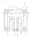
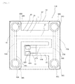
- Fig. 1 is a plan view illustrating a seating sensor according to a first embodiment of the present invention.
- a seating sensor 100 includes a first electrode sheet 10, a second electrode sheet 20 overlapped with the first electrode sheet 10, and a spacer sandwiched between the first electrode sheet 10 and the second electrode sheet 20 as main components.
- Fig. 2 is a plan view illustrating the first electrode sheet 10 shown in Fig. 1 .
- the first electrode sheet 10 has a flexible film-like first insulating sheet 15 as a base table, first electrodes 14A to 14D formed on the surface of the first insulating sheet 15, and terminals 42A and 42B formed on the surface of the first insulating sheet 15 as main components.
- the first insulating sheet 15 includes a first part 11 and a second part 12.
- the first part 11 includes a pair of strip-like lateral portions 11A and 11B having equal shapes and parallel to each other and a strip-like intermediate portion 11C extending in a direction perpendicular to the lateral portions 11A and 11B between the lateral portions 11A and 11B and connected to respective intermediate parts of the lateral portions 11A and 11B. In this manner, the first part 11 is formed approximately in an H shape shown to be surrounded by a dotted line 11L.
- the second part 12 is formed in a strip shape, extends in a direction perpendicular to the intermediate portion 11C of the first part, is connected at one end to an intermediate part of the intermediate portion 11C, and has the other end as a free end.
- the second part 12 and the intermediate portion 11C approximately form a T shape.
- the second part 12 is surrounded by a dotted line 12L.
- an edge of the second part 12 on the free end side is located on a line connecting respective edges of the lateral portions 11A and 11B of the first part 11 on a side on which the second part 12 is formed. Accordingly, the second part 12 of the first insulating sheet 15 is housed without protruding from an inside of a minimum rectangular area S1 containing the first part 11 of the first insulating sheet 15.
- first electrodes 14A to 14D are formed approximately in circular shapes and are provided on the first part 11.
- first electrodes 14A and 14B are provided on the surface of the lateral portion 11A to be spaced at predetermined distances from edges of both the ends of the lateral portion 11A of the first part 11, respectively.
- first electrode 14A and the first electrode 14B are connected to a linear first conductor 16A provided between the first electrode 14A and the first electrode 14B on the surface of the lateral portion 11A.
- a first conductor 16C is branched and extends on the intermediate portion 11C.
- first electrodes 14C and 14D are provided on the surface of the lateral portion 11B to be spaced at predetermined distances from edges of both the ends of the lateral portion 11B of the first part 11, respectively.
- first electrode 14C and the first electrode 14D are connected to a linear first conductor 16B provided between the first electrode 14C and the first electrode 14D on the surface of the lateral portion 11B.
- a first conductor 16D is branched and extends on the intermediate portion 11C.
- the linear first conductor 16A is provided between the first electrode 14A and the first electrode 14B
- the linear first conductor 16B is provided between the first electrode 14C and the first electrode 14D
- the first conductor 16C and the first conductor 16D extend to the side of the intermediate portion 11C from the first conductor 16A and the first conductor 16B, respectively.
- the first conductors 16A to 16D are arranged within a minimum rectangular area S2 containing the respective first electrodes 14A to 14D.
- the terminals 42A and 42B are formed approximately in rectangular shapes and are provided side by side in a direction perpendicular to a longitudinal direction of the second part 12 at locations on the surface of the second part 12 spaced at predetermined distances from the edge on the free end side.
- the terminal 42A is connected to a second conductor 17A provided on the surface of the second part 12, and the terminal 42B is connected to a second conductor 17B provided on the surface of the second part.
- the second conductors 17A and 17B extend in parallel with each other along the longitudinal direction of the first part 12.
- the second conductor 17A is connected to the first conductor 16C at the intermediate portion 11C while the second conductor 17B is connected to the first conductor 16D at the intermediate portion 11C.
- Fig. 3 is a plan view illustrating the second electrode sheet shown in Fig. 1 .
- the second electrode sheet has a flexible film-like second insulating sheet 25 and second electrodes 24A to 24D formed on the surface of the second insulating sheet 25 as main components.
- the second insulating sheet 25 includes a first part 21 and a second part 22.
- the first part 21 of the second insulating sheet 25 includes a pair of strip-like lateral portions 21A and 21B having equal shapes and parallel to each other and a strip-like intermediate portion 21C extending in a direction perpendicular to the lateral portions 21A and 21B and connected to respective intermediate parts of the lateral portions 21A and 21B between the lateral portions 21A and 21B.
- the first part 21 of the second insulating sheet 25 corresponds to the first part 11 of the first insulating sheet 15 in shape. Accordingly, the first part 21 is formed approximately in an H shape surrounded by a dotted line 21L.
- the second part 22 of the second insulating sheet 25 is formed in a strip shape having an equal width to and having a shorter length than those of the second part 12 of the first insulating sheet 15, extends in a direction perpendicular to the intermediate portion 21C, is connected at one end perpendicularly to an intermediate part of the intermediate portion 21C, and has the other end as a free end.
- the second part 22 of the second insulating sheet 25 is long enough for the terminals 42A and 42B of the first electrode sheet 10 to be exposed in a state where the second electrode sheet 20 and the first electrode sheet 10 are aligned and overlapped as shown in Fig. 1 .
- the second part 22 is surrounded by a dotted line 22L.
- the second electrodes 24A to 24D have equal shapes and sizes to those of the first electrodes 14A to 14D.
- the second electrodes 24A to 24D are provided at locations, overlapped with the first electrodes 14A to 14D, on the surface of the second insulating sheet 25 on the side of the first electrode sheet 10 when the second insulating sheet 25 is overlapped with the first electrode sheet 10.
- the second electrode 24A and the second electrode 24B are connected to a linear first conductor 26A provided between the second electrode 24A and the second electrode 24B on the surface of the second insulating sheet 25.
- the second electrode 24C and the second electrode 24D are connected to a linear first conductor 26B provided between the second electrode 24C and the second electrode 24D on the surface of the second insulating sheet 25. Further, the first conductor 26A and the first conductor 26B are connected to a first conductor 27 formed on the surface of the intermediate portion 21C of the second insulating sheet 25.
- the linear first conductor 26A is provided between the second electrodes 24A and 24B
- the linear first conductor 26B is provided between the second electrodes 24C and 24D
- the first conductor 27 is connected to the first conductor 26A and the first conductor 26B. Accordingly, when the second insulating sheet 25 is overlapped with the first electrode sheet 10, and the second insulating sheet 25 is seen in a direction perpendicular to the second insulating sheet 25, the first conductors 26A, 26B, and 27 are arranged within the minimum rectangular area S2 containing the respective first electrodes 14A to 14D.
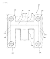
- Fig. 4 is a plan view illustrating the spacer sandwiched between the first electrode sheet 10 and the second electrode sheet 20.
- a spacer 30 is made of a flexible insulating sheet. As shown in Fig. 4 , the spacer 30 corresponds to the second electrode sheet 20 in external shape.
- opening portions 34A to 34D are formed at the spacer 30.
- the opening portions 34A to 34D are formed approximately in circular shapes at the circumferences and are formed to have larger diameters than those of the first electrodes 14A to 14D.
- the opening portions 34A to 34D are formed at locations to allow the first electrodes 14A to 14D to be arranged inside the opening portions 34A to 34D in a case where the spacer 30 is overlapped with the first electrode sheet 10, and where the spacer 30 is seen in a direction perpendicular to the spacer 30.
- the opening portions 34A to 34D are connected to a slit 35 for air release, and the slit 35 communicates with the outside of the spacer 30 by an air exhaust port 35A.
- Fig. 5 is a cross-sectional view illustrating a cross-sectional state along the line V-V shown in Fig. 1
- Fig. 6 is a circuit diagram illustrating a circuit configuration of the seating sensor 100 shown in Fig. 1 as an equivalent circuit
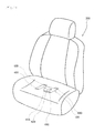
- Fig. 7 illustrates a state in which the seating sensor 100 shown in Fig. 1 is arranged in a seat.
- the first electrode sheet 10 and the second electrode sheet 20 are overlapped with the spacer 30 inbetween and are fixed to each other and integrated by the adhesive applied on both the surfaces of the spacer 30, as described above.
- a minimum rectangular area containing the respective switches 40A to 40D is an equal area to the minimum rectangular area S2 containing the respective first electrodes 14A to 14D. Accordingly, the first conductors provided on the first insulating sheet 15 and the second insulating sheet 25 are arranged within the minimum rectangular area S2 containing the respective switches 40A to 40D.
- each of the switches 40A to 40D configured in this manner detects a pressing force. This state will be described with reference to Figs. 1 and 5 .
- the first electrode 14A of the first electrode sheet 10 and the second electrode 24A of the second electrode sheet 20 are arranged inside the opening portion 34A provided in the spacer 30 in a case where the seating sensor 100 is seen in the direction perpendicular to the seating sensor 100 as described above.
- the first electrode 14A and the second electrode 24A are opposed to each other to be spaced at a predetermined distance by the spacer 30 as shown in Fig. 5 .
- the switch 40A is constituted by the first electrode 14A and the second electrode 24A on the first insulating sheet 15.
- the insulating sheet 15 provided with the first electrode 14A and the insulating sheet 25 provided with the second electrode 24A are respectively flexible film-like sheets.
- the second insulating sheet 25 is flexed to cause the second electrode 24A to contact the first electrode 14A when pressing forces F are applied in directions perpendicular to both the surfaces of the seating sensor 100.
- the first insulating sheet 15 is more excellent in flexibility than the second insulating sheet 25
- the first insulating sheet 15 is flexed to cause the first electrode 14A to contact the second electrode 24A when the pressing forces F are applied in the directions perpendicular to both the surfaces of the seating sensor 100.
- the contact between the first electrode 14A and the second electrode 24A causes the switch 40A to be turned on. Meanwhile, when the second insulating sheet 25 or the first insulating sheet 15 is flexed, air in the opening portion 34A is exhausted from the slit 35 shown in Fig. 4 , and thus the second insulating sheet 25 or the first insulating sheet 15 can be flexed appropriately when the pressing forces F are applied.
- the switches 40A to 40D configured in this manner are connected to one another by the first conductors 16A and 16B formed on the surface of the first part 11 of the first insulating sheet 15 and the first conductors 26A, 26B, and 27 formed on the surface of the first part 21 of the second insulating sheet 25 as shown in Fig. 6 .
- the respective switches 40A to 40D are connected in this manner to constitute a sensor portion 1, and the sensor portion 1 is provided on the first part 11 of the first insulating sheet 15. It is to be noted that the entirety of the sensor portion 1 does not need to contact the first insulating sheet 15 as long as the sensor portion 1 is provided on the first insulating sheet 15.
- Such a seating sensor 100 is arranged on a cushion pad under a surface cover at a seat 200 of a vehicle or the like as shown in Fig. 7 .
- the switches 40A and 40B are arranged on one side with reference to a line passing at the center of the seat 200 in a direction in which a person seated is directed, and the switches 40C and 40D are arranged on the other side.
- the cushion pad under the surface cover at the seat 200 is provided a hole, and the hole is in an elongated shape in a direction perpendicular to the direction in which the person seated is directed on the surface of the cushion pad.
- the second part of the first insulating sheet provided with the connector portion 2 is bent and inserted into the inside of the cushion pad through this hole.
- the terminals 42A and 42B are electrically connected to not shown external power supply and measuring portion, and voltage is applied to the terminals 42A and 42B. In this manner, a sensed signal sensed by the sensor portion 1 is output to the not shown measuring portion to detect the seating of the occupant.
- the insulating sheet 15 of the first electrode sheet 10, the insulating sheet 25 of the second electrode sheet 20, and the spacer 30 are made of a flexible insulating resin.
- the resin include polyethylene terephthalate (PET), polyethylene naphthalate (PEN), and polyimide (PI).
- PET polyethylene terephthalate
- PEN polyethylene naphthalate
- PI polyimide
- PEN is preferable in terms of heat resistance.
- PEN is preferable in terms of heat resistance.
- PEN is preferable in terms of heat resistance.
- PEN is preferable in terms of heat resistance.
- PEN is preferable in terms of heat resistance.
- an acrylic adhesive is preferable, and an example of this is one based on an acrylic polymer using one or more kinds of (meth)acrylic alkyl ester as monomer components.
- first electrodes 14A to 14D, the second electrodes 24A to 24D, the first conductors 16A to 16D, 26A, 26B, and 27, the second conductors 17A and 17B, and the terminals 42A and 42B are made of a conductive paste, a metallic foil formed by plating, or the like. Some of them may be made of the conductive paste while the other parts may be made of the metallic foil by plating. Examples of the conductive paste include various metallic pastes such as a silver paste and a carbon paste. Further, examples of the metallic foil formed by plating include copper, nickel, and a laminated body of these.
- the first electrode sheet 10, the second electrode sheet 20, and the spacer 30 before being punched are prepared (preparing process).
- the first electrodes 14A to 14D, the first conductors 16A to 16D, the second conductors 17A and 17B, and the terminals 42A and 42B (hereinafter, a first circuit pattern).
- a plurality of first circuit patterns are formed on one insulating sheet.
- the conductive paste such as the silver paste
- the conductive paste is applied and dried on a location on the insulating sheet at which the first circuit pattern is formed.
- the location on the insulating sheet at which the first circuit pattern is formed is plated. In this manner, the plurality of first circuit patterns are formed on the insulating sheet to bring a state in which the plurality of first electrode sheets 10 before being punched are connected to one another.
- the second electrodes 24A to 24D and the first conductors 26A, 26B, and 27 (hereinafter, a second circuit pattern).
- a plurality of second circuit patterns are formed on one insulating sheet to align with the first circuit patterns.
- the second circuit patterns have only to be formed in a similar method to the method for forming the first circuit patterns on the insulating sheet. Meanwhile, locations of the second circuit patterns are adjusted so that the first electrodes and the second electrodes may be opposed when the insulating sheet on which the second circuit patterns are formed is overlapped on the insulating sheet on which the first circuit patterns are formed.
- the insulating sheet on which the second circuit patterns are formed has formed therein an opening at a part corresponding to the terminals 42A and 42B so that the terminals 42A and 42B of the first electrode sheet may be exposed from the insulating sheet on which the second circuit patterns are formed when the insulating sheet on which the second circuit patterns are formed is overlapped on the insulating sheet on which the first circuit patterns are formed.
- the plurality of second circuit patterns are formed on the insulating sheet to bring a state in which the plurality of second electrode sheets 20 before being punched are connected to one another.
- the adhesive is first applied on both the surfaces of an insulating sheet. Thereafter, the opening portions 34A to 34D and the slit 35 are formed by punching. At this time, a plurality of opening portions 34A to 34D and slits 35 are formed on one insulating sheet to align with the first circuit patterns.
- the first electrode sheets 10, spacers 30, and second electrode sheets 20 before being punched prepared in this manner are aligned, overlapped, and integrated to sandwich the spacers 30 between the first electrode sheets 10 and the second electrode sheets 20 (integrating process).
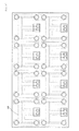
- Fig. 8 is a plan view illustrating a state in which the insulating sheet on which the plurality of spacers are formed and the insulating sheet on which the plurality of second circuit patterns are formed are overlapped on the insulating sheet on which the plurality of first circuit patterns are formed and integrated. That is, it is a plan view illustrating a state in which multiple seating sensors 100 before being punched are formed.
- the second part of the insulating sheet 15 is arranged within the minimum rectangular area S1 containing the first part of the insulating sheet 15 at which the sensor portion 1 is provided. Accordingly, as shown in Fig. 8 , a distance between the adjacent seating sensors 100 can be minimum, and many seating sensors 100 are formed on the film-like insulating sheet as a material for the insulating sheet 15.
- each seating sensor 100 is punched (punching process). Punching is done along the external shape of each seating sensor 100 shown in Fig. 8 by a punching machine.
- the first conductors 16A to 16D, 26A, 26B, and 27 connected to the respective switches 40A to 40D are arranged within the minimum rectangular area S2 containing the respective switches. Since the first conductors 16A to 16D, 26A, 26B, and 27 do not extend to the outside from the minimum rectangular area S2 containing the respective switches 40A to 40D, the sensor portion 1 is reduced in size. Further, the second part 12 of the first insulating sheet 15 at which the terminals 42A and 42B and the second conductors 17A and 17B are provided is arranged within the minimum rectangular area S1 containing the first part 11 of the insulating sheet 15 at which the sensor portion 1 is provided.
- the seating sensor 100 Since the second part 12 of the first insulating sheet 15 does not extend to the outside from the minimum rectangular area S1 containing the first part 11, the seating sensor 100 is housed within the minimum rectangular area S1 containing the first part 11. Accordingly, more seating sensors 100 can be formed on the insulating sheet as the material for the first insulating sheet 15 than in a case of another seating sensor having the same switch arrangement. Thus, the seating sensor 100 enables reduction in a material cost and inexpensive manufacturing.
- the seating sensor 100 is housed within the minimum rectangular area S1 containing the first part 11 as described above, the seating sensor 100 can be reduced in size more than in a case of another seating sensor having the same switch arrangement. Accordingly, a degree of freedom of arrangement is improved when the seating sensor 100 is to be arranged in the seat 200.
- the AND circuit is constituted by a first switch group consisting of the switches 40A and 40B and a second switch group consisting of the switches 40C and 40D
- a pressing force applied only to switches in either the first switch group or the second switch group is not determined as the seating of the occupant even when it is applied, which can prevent false detection.
- the OR circuit is constituted by the switch 40A and the switch 40B in the first switch group, and the OR circuit is constituted by the switch 40C and the switch 40D in the second switch group. Accordingly, when at least one switch in the first switch group and at least one switch in the second switch group are turned on, the seating of the occupant can be detected. Hence, the seating of the occupant can be detected with excellent accuracy.
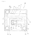
- FIG. 9 is a plan view illustrating a seating sensor 110 according to the second embodiment of the present invention.
- the seating sensor 110 in the present embodiment differs from the seating sensor 100 in the first embodiment in that the second part 12 of the first insulating sheet 15 provided with the connector portion 2 is connected perpendicularly to the intermediate part of the lateral portion 11B of the first part 11.
- the second part 12 of the first insulating sheet 15 provided with the connector portion 2 can be bent centering on an axis in a direction perpendicular to a longitudinal direction of the second part 12.
- a width direction of the second part 12 has a parallel relationship with a longitudinal direction of the lateral portion 11B
- a thickness direction of the second part 12 has a perpendicular relationship with the longitudinal direction of the lateral portion 11B.
- the connector portion can be inserted in a hole provided in the cushion pad under the surface cover at the seat 200 in a case where the hole is in an elongated shape in a direction in which the person seated is directed on the surface of the cushion pad.
- the terminals 42A and 42B are connected to the power supply and measuring portion.
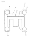
- Fig. 10 is a plan view illustrating a seating sensor 120 according to the third embodiment of the present invention.
- the seating sensor 120 in the present embodiment differs from the seating sensor 110 in the second embodiment in that the switch 40D is not provided.
- an OR circuit is constituted by the switch 40A and the switch 40B, and an AND circuit is constituted by a switch group, consisting of the switch 40A and the switch 40B, and the switch 40C.
- a manufacturing cost can be reduced as much as dispensation with the switch 40D, and the seating sensor can be manufactured more inexpensively.
- the number of switches is four in the first and second embodiments, the present invention is not limited to this, and the number of switches may be five or more.
- first electrodes 14A to 14D and the second electrodes 24A to 24D of the respective switches 40A to 40D correspond to each other in shape and size and are overlapped with each other completely, the present invention is not limited to this, and the first electrodes 14A to 14D and the second electrodes 24A to 24D may differ from each other in size and shape as long as the pressing forces can be detected.
- the present invention provides a seating sensor that is reduced in size and can be manufactured inexpensively.
Landscapes
- Engineering & Computer Science (AREA)
- Mechanical Engineering (AREA)
- Aviation & Aerospace Engineering (AREA)
- Transportation (AREA)
- Push-Button Switches (AREA)
- Seats For Vehicles (AREA)
- Chair Legs, Seat Parts, And Backrests (AREA)
- Geophysics And Detection Of Objects (AREA)
Applications Claiming Priority (2)
| Application Number | Priority Date | Filing Date | Title |
|---|---|---|---|
| JP2009131506 | 2009-05-29 | ||
| PCT/JP2010/058090 WO2010137464A1 (ja) | 2009-05-29 | 2010-05-13 | 着座センサ |
Publications (3)
| Publication Number | Publication Date |
|---|---|
| EP2437275A1 true EP2437275A1 (de) | 2012-04-04 |
| EP2437275A4 EP2437275A4 (de) | 2014-07-09 |
| EP2437275B1 EP2437275B1 (de) | 2016-01-06 |
Family
ID=43222577
Family Applications (1)
| Application Number | Title | Priority Date | Filing Date |
|---|---|---|---|
| EP10780419.7A Not-in-force EP2437275B1 (de) | 2009-05-29 | 2010-05-13 | Sitzbesetzungssensor |
Country Status (5)
| Country | Link |
|---|---|
| US (1) | US9018546B2 (de) |
| EP (1) | EP2437275B1 (de) |
| JP (1) | JP5244970B2 (de) |
| CN (1) | CN102405505B (de) |
| WO (1) | WO2010137464A1 (de) |
Cited By (2)
| Publication number | Priority date | Publication date | Assignee | Title |
|---|---|---|---|---|
| EP3109092A1 (de) * | 2015-06-04 | 2016-12-28 | Aisin Seiki Kabushiki Kaisha | Vorrichtung zur sitzbelegungserkennung |
| KR20200120735A (ko) * | 2018-04-12 | 2020-10-21 | 가부시키가이샤후지쿠라 | 착좌 센서 |
Families Citing this family (8)
| Publication number | Priority date | Publication date | Assignee | Title |
|---|---|---|---|---|
| JP5243639B1 (ja) * | 2012-04-06 | 2013-07-24 | 株式会社フジクラ | 座席装置 |
| US20140316607A1 (en) * | 2013-04-18 | 2014-10-23 | Ford Global Technologeis, Llc | Occupant presence detection and identification |
| JP5604566B1 (ja) * | 2013-07-05 | 2014-10-08 | 株式会社フジクラ | メンブレンスイッチ及び座席装置 |
| CN104590183A (zh) * | 2015-01-30 | 2015-05-06 | 无锡桑尼安科技有限公司 | 提高停车状态下的安全性的内部监控系统 |
| IT201700006845A1 (it) * | 2017-01-23 | 2018-07-23 | B810 Soc A Responsabilita Limitata | Sensore di pressione |
| JP6574213B2 (ja) * | 2017-03-08 | 2019-09-11 | アイシン精機株式会社 | 着座センサ |
| TWI653651B (zh) * | 2017-10-27 | 2019-03-11 | 致伸科技股份有限公司 | 鍵盤 |
| US12427894B1 (en) * | 2024-05-15 | 2025-09-30 | RB Distribution, Inc. | Vehicle seat occupancy sensor |
Family Cites Families (23)
| Publication number | Priority date | Publication date | Assignee | Title |
|---|---|---|---|---|
| US3718791A (en) * | 1971-09-16 | 1973-02-27 | Gen Motors Corp | Pressure responsive switch |
| US3859485A (en) * | 1973-02-26 | 1975-01-07 | Essex International Inc | Occupant sensor seat switch |
| JP2909961B2 (ja) * | 1996-05-29 | 1999-06-23 | アイシン精機株式会社 | 着座検知装置 |
| KR100369314B1 (ko) | 1996-10-04 | 2003-01-24 | 마쯔시다덴기산교 가부시키가이샤 | 좌석용 인체 검출장치 |
| CN1129385C (zh) * | 1996-10-04 | 2003-12-03 | 松下电器产业株式会社 | 座位用人体检测装置 |
| US5986221A (en) * | 1996-12-19 | 1999-11-16 | Automotive Systems Laboratory, Inc. | Membrane seat weight sensor |
| JP3962959B2 (ja) * | 1996-12-20 | 2007-08-22 | アイシン精機株式会社 | 感圧スイッチ |
| JPH11297157A (ja) * | 1998-04-10 | 1999-10-29 | Fujikura Ltd | 着座センサ用メンブレンスイッチの固定方法及び着座センサ用メンブレンスイッチ |
| JP3827875B2 (ja) * | 1999-01-27 | 2006-09-27 | アルプス電気株式会社 | メンブレンスイッチ |
| JP3726555B2 (ja) * | 1999-05-18 | 2005-12-14 | 日産自動車株式会社 | シート用の圧力センサユニット |
| JP2001116636A (ja) * | 1999-10-22 | 2001-04-27 | Matsushita Electric Ind Co Ltd | 感圧スイッチ及びこれを用いた着座検出装置 |
| JP4374604B2 (ja) * | 1999-11-09 | 2009-12-02 | アイシン精機株式会社 | 着座検知装置 |
| LU90578B1 (de) * | 2000-05-05 | 2001-11-06 | Iee Sarl | Sensormatte fuer Fahrzeug |
| JP4595267B2 (ja) * | 2001-08-29 | 2010-12-08 | アイシン精機株式会社 | 感圧スイッチ |
| US6918612B2 (en) * | 2003-03-07 | 2005-07-19 | Autoliv Asp, Inc. | Electronic seat occupant classification system |
| JP4448379B2 (ja) * | 2003-05-20 | 2010-04-07 | 株式会社フジクラ | 着座検出スイッチ |
| DE602004024258D1 (de) * | 2003-05-20 | 2009-12-31 | Fujikura Ltd | Sitzerkennungsschalter |
| CN1791954B (zh) * | 2003-05-20 | 2010-07-14 | 株式会社藤仓 | 着座检测开关 |
| DE502004002969D1 (de) * | 2003-06-23 | 2007-04-05 | Iee Sarl | Sitzbelegungssensor |
| JP2008051592A (ja) * | 2006-08-23 | 2008-03-06 | Denso Corp | 乗員検知センサ |
| JP4306715B2 (ja) * | 2006-10-25 | 2009-08-05 | アイシン精機株式会社 | 感圧スイッチ |
| JP5103027B2 (ja) * | 2007-01-29 | 2012-12-19 | トヨタ紡織株式会社 | 車両用シート |
| US8009056B2 (en) * | 2008-09-25 | 2011-08-30 | United Security Products, Inc. | Movement monitor for medical patients |
-
2010
- 2010-05-13 WO PCT/JP2010/058090 patent/WO2010137464A1/ja not_active Ceased
- 2010-05-13 EP EP10780419.7A patent/EP2437275B1/de not_active Not-in-force
- 2010-05-13 JP JP2011515971A patent/JP5244970B2/ja not_active Expired - Fee Related
- 2010-05-13 CN CN201080017235.1A patent/CN102405505B/zh not_active Expired - Fee Related
-
2011
- 2011-11-29 US US13/306,649 patent/US9018546B2/en active Active
Cited By (3)
| Publication number | Priority date | Publication date | Assignee | Title |
|---|---|---|---|---|
| EP3109092A1 (de) * | 2015-06-04 | 2016-12-28 | Aisin Seiki Kabushiki Kaisha | Vorrichtung zur sitzbelegungserkennung |
| KR20200120735A (ko) * | 2018-04-12 | 2020-10-21 | 가부시키가이샤후지쿠라 | 착좌 센서 |
| US11673488B2 (en) | 2018-04-12 | 2023-06-13 | Fujikura Ltd. | Sitting sensor |
Also Published As
| Publication number | Publication date |
|---|---|
| EP2437275A4 (de) | 2014-07-09 |
| JP5244970B2 (ja) | 2013-07-24 |
| CN102405505B (zh) | 2014-12-24 |
| WO2010137464A1 (ja) | 2010-12-02 |
| EP2437275B1 (de) | 2016-01-06 |
| CN102405505A (zh) | 2012-04-04 |
| US9018546B2 (en) | 2015-04-28 |
| JPWO2010137464A1 (ja) | 2012-11-12 |
| US20120125698A1 (en) | 2012-05-24 |
Similar Documents
| Publication | Publication Date | Title |
|---|---|---|
| EP2437275B1 (de) | Sitzbesetzungssensor | |
| JP5520012B2 (ja) | 着座センサ | |
| US12080910B2 (en) | Wiring material and battery module | |
| EP2774805A1 (de) | Sitzbesetzungssensor | |
| US7528333B2 (en) | Seating detection switch | |
| CN106414164B (zh) | 载荷检测传感器单元 | |
| JP5324548B2 (ja) | 着座センサ、及び、それを用いた座席装置 | |
| EP2413120A1 (de) | Druckempfindliche Wandleranordnung und Ansteuerungsverfahren für ein System mit einer derartigen Anordnung | |
| WO2017040285A1 (en) | Battery including an on-cell indicator | |
| CN101191724B (zh) | 座椅传感器 | |
| JP2010181303A (ja) | 感圧センサおよびこれを用いた乗員検知装置 | |
| JP5874434B2 (ja) | 端子接続構造体 | |
| JP5782310B2 (ja) | 座席装置 | |
| JP5738694B2 (ja) | 着座センサ及び座席装置 | |
| JP5604277B2 (ja) | 着座センサ、及び、それを用いた座席装置 | |
| CN212585880U (zh) | 一种微型压力传感器 | |
| JP5903923B2 (ja) | 着座荷重検出装置 | |
| JP3979818B2 (ja) | 位置センサ | |
| JP2019109213A (ja) | 分布圧力センサ | |
| JPH0946858A (ja) | 分岐接続箱 | |
| JP2017073353A (ja) | 2系統スイッチ回路 | |
| JP2012086805A (ja) | 着座センサ、及び、それを用いた座席装置 | |
| JP2018203066A (ja) | 荷重検知センサ | |
| JP2007200753A (ja) | 電気的特性用の検査測定治具 | |
| WO2016083237A1 (en) | Vehicle seat |
Legal Events
| Date | Code | Title | Description |
|---|---|---|---|
| PUAI | Public reference made under article 153(3) epc to a published international application that has entered the european phase |
Free format text: ORIGINAL CODE: 0009012 |
|
| 17P | Request for examination filed |
Effective date: 20111228 |
|
| AK | Designated contracting states |
Kind code of ref document: A1 Designated state(s): AL AT BE BG CH CY CZ DE DK EE ES FI FR GB GR HR HU IE IS IT LI LT LU LV MC MK MT NL NO PL PT RO SE SI SK SM TR |
|
| DAX | Request for extension of the european patent (deleted) | ||
| A4 | Supplementary search report drawn up and despatched |
Effective date: 20140606 |
|
| RIC1 | Information provided on ipc code assigned before grant |
Ipc: H01H 13/18 20060101ALI20140602BHEP Ipc: H01H 13/702 20060101ALI20140602BHEP Ipc: B60N 2/44 20060101ALI20140602BHEP Ipc: H01H 13/712 20060101ALI20140602BHEP Ipc: A47C 7/62 20060101ALI20140602BHEP Ipc: B60N 2/00 20060101ALI20140602BHEP Ipc: H01H 3/14 20060101ALI20140602BHEP Ipc: H01H 13/16 20060101AFI20140602BHEP Ipc: B60R 21/015 20060101ALI20140602BHEP |
|
| GRAP | Despatch of communication of intention to grant a patent |
Free format text: ORIGINAL CODE: EPIDOSNIGR1 |
|
| INTG | Intention to grant announced |
Effective date: 20150729 |
|
| GRAS | Grant fee paid |
Free format text: ORIGINAL CODE: EPIDOSNIGR3 |
|
| GRAA | (expected) grant |
Free format text: ORIGINAL CODE: 0009210 |
|
| AK | Designated contracting states |
Kind code of ref document: B1 Designated state(s): AL AT BE BG CH CY CZ DE DK EE ES FI FR GB GR HR HU IE IS IT LI LT LU LV MC MK MT NL NO PL PT RO SE SI SK SM TR |
|
| REG | Reference to a national code |
Ref country code: GB Ref legal event code: FG4D |
|
| REG | Reference to a national code |
Ref country code: CH Ref legal event code: EP |
|
| REG | Reference to a national code |
Ref country code: IE Ref legal event code: FG4D |
|
| REG | Reference to a national code |
Ref country code: AT Ref legal event code: REF Ref document number: 769483 Country of ref document: AT Kind code of ref document: T Effective date: 20160215 |
|
| REG | Reference to a national code |
Ref country code: DE Ref legal event code: R096 Ref document number: 602010029998 Country of ref document: DE |
|
| REG | Reference to a national code |
Ref country code: LT Ref legal event code: MG4D |
|
| REG | Reference to a national code |
Ref country code: NL Ref legal event code: MP Effective date: 20160106 |
|
| REG | Reference to a national code |
Ref country code: AT Ref legal event code: MK05 Ref document number: 769483 Country of ref document: AT Kind code of ref document: T Effective date: 20160106 |
|
| PG25 | Lapsed in a contracting state [announced via postgrant information from national office to epo] |
Ref country code: NL Free format text: LAPSE BECAUSE OF FAILURE TO SUBMIT A TRANSLATION OF THE DESCRIPTION OR TO PAY THE FEE WITHIN THE PRESCRIBED TIME-LIMIT Effective date: 20160106 |
|
| PG25 | Lapsed in a contracting state [announced via postgrant information from national office to epo] |
Ref country code: FI Free format text: LAPSE BECAUSE OF FAILURE TO SUBMIT A TRANSLATION OF THE DESCRIPTION OR TO PAY THE FEE WITHIN THE PRESCRIBED TIME-LIMIT Effective date: 20160106 Ref country code: ES Free format text: LAPSE BECAUSE OF FAILURE TO SUBMIT A TRANSLATION OF THE DESCRIPTION OR TO PAY THE FEE WITHIN THE PRESCRIBED TIME-LIMIT Effective date: 20160106 Ref country code: NO Free format text: LAPSE BECAUSE OF FAILURE TO SUBMIT A TRANSLATION OF THE DESCRIPTION OR TO PAY THE FEE WITHIN THE PRESCRIBED TIME-LIMIT Effective date: 20160406 Ref country code: HR Free format text: LAPSE BECAUSE OF FAILURE TO SUBMIT A TRANSLATION OF THE DESCRIPTION OR TO PAY THE FEE WITHIN THE PRESCRIBED TIME-LIMIT Effective date: 20160106 Ref country code: GR Free format text: LAPSE BECAUSE OF FAILURE TO SUBMIT A TRANSLATION OF THE DESCRIPTION OR TO PAY THE FEE WITHIN THE PRESCRIBED TIME-LIMIT Effective date: 20160407 Ref country code: IT Free format text: LAPSE BECAUSE OF FAILURE TO SUBMIT A TRANSLATION OF THE DESCRIPTION OR TO PAY THE FEE WITHIN THE PRESCRIBED TIME-LIMIT Effective date: 20160106 |
|
| PG25 | Lapsed in a contracting state [announced via postgrant information from national office to epo] |
Ref country code: LT Free format text: LAPSE BECAUSE OF FAILURE TO SUBMIT A TRANSLATION OF THE DESCRIPTION OR TO PAY THE FEE WITHIN THE PRESCRIBED TIME-LIMIT Effective date: 20160106 Ref country code: SE Free format text: LAPSE BECAUSE OF FAILURE TO SUBMIT A TRANSLATION OF THE DESCRIPTION OR TO PAY THE FEE WITHIN THE PRESCRIBED TIME-LIMIT Effective date: 20160106 Ref country code: BE Free format text: LAPSE BECAUSE OF NON-PAYMENT OF DUE FEES Effective date: 20160531 Ref country code: IS Free format text: LAPSE BECAUSE OF FAILURE TO SUBMIT A TRANSLATION OF THE DESCRIPTION OR TO PAY THE FEE WITHIN THE PRESCRIBED TIME-LIMIT Effective date: 20160506 Ref country code: AT Free format text: LAPSE BECAUSE OF FAILURE TO SUBMIT A TRANSLATION OF THE DESCRIPTION OR TO PAY THE FEE WITHIN THE PRESCRIBED TIME-LIMIT Effective date: 20160106 Ref country code: LV Free format text: LAPSE BECAUSE OF FAILURE TO SUBMIT A TRANSLATION OF THE DESCRIPTION OR TO PAY THE FEE WITHIN THE PRESCRIBED TIME-LIMIT Effective date: 20160106 Ref country code: PT Free format text: LAPSE BECAUSE OF FAILURE TO SUBMIT A TRANSLATION OF THE DESCRIPTION OR TO PAY THE FEE WITHIN THE PRESCRIBED TIME-LIMIT Effective date: 20160506 Ref country code: PL Free format text: LAPSE BECAUSE OF FAILURE TO SUBMIT A TRANSLATION OF THE DESCRIPTION OR TO PAY THE FEE WITHIN THE PRESCRIBED TIME-LIMIT Effective date: 20160106 |
|
| REG | Reference to a national code |
Ref country code: DE Ref legal event code: R097 Ref document number: 602010029998 Country of ref document: DE |
|
| PG25 | Lapsed in a contracting state [announced via postgrant information from national office to epo] |
Ref country code: DK Free format text: LAPSE BECAUSE OF FAILURE TO SUBMIT A TRANSLATION OF THE DESCRIPTION OR TO PAY THE FEE WITHIN THE PRESCRIBED TIME-LIMIT Effective date: 20160106 Ref country code: EE Free format text: LAPSE BECAUSE OF FAILURE TO SUBMIT A TRANSLATION OF THE DESCRIPTION OR TO PAY THE FEE WITHIN THE PRESCRIBED TIME-LIMIT Effective date: 20160106 |
|
| PLBE | No opposition filed within time limit |
Free format text: ORIGINAL CODE: 0009261 |
|
| STAA | Information on the status of an ep patent application or granted ep patent |
Free format text: STATUS: NO OPPOSITION FILED WITHIN TIME LIMIT |
|
| PG25 | Lapsed in a contracting state [announced via postgrant information from national office to epo] |
Ref country code: RO Free format text: LAPSE BECAUSE OF FAILURE TO SUBMIT A TRANSLATION OF THE DESCRIPTION OR TO PAY THE FEE WITHIN THE PRESCRIBED TIME-LIMIT Effective date: 20160106 Ref country code: SK Free format text: LAPSE BECAUSE OF FAILURE TO SUBMIT A TRANSLATION OF THE DESCRIPTION OR TO PAY THE FEE WITHIN THE PRESCRIBED TIME-LIMIT Effective date: 20160106 Ref country code: SM Free format text: LAPSE BECAUSE OF FAILURE TO SUBMIT A TRANSLATION OF THE DESCRIPTION OR TO PAY THE FEE WITHIN THE PRESCRIBED TIME-LIMIT Effective date: 20160106 Ref country code: CZ Free format text: LAPSE BECAUSE OF FAILURE TO SUBMIT A TRANSLATION OF THE DESCRIPTION OR TO PAY THE FEE WITHIN THE PRESCRIBED TIME-LIMIT Effective date: 20160106 |
|
| 26N | No opposition filed |
Effective date: 20161007 |
|
| PG25 | Lapsed in a contracting state [announced via postgrant information from national office to epo] |
Ref country code: LU Free format text: LAPSE BECAUSE OF FAILURE TO SUBMIT A TRANSLATION OF THE DESCRIPTION OR TO PAY THE FEE WITHIN THE PRESCRIBED TIME-LIMIT Effective date: 20160513 Ref country code: BE Free format text: LAPSE BECAUSE OF FAILURE TO SUBMIT A TRANSLATION OF THE DESCRIPTION OR TO PAY THE FEE WITHIN THE PRESCRIBED TIME-LIMIT Effective date: 20160106 |
|
| REG | Reference to a national code |
Ref country code: CH Ref legal event code: PL |
|
| PG25 | Lapsed in a contracting state [announced via postgrant information from national office to epo] |
Ref country code: CH Free format text: LAPSE BECAUSE OF NON-PAYMENT OF DUE FEES Effective date: 20160531 Ref country code: LI Free format text: LAPSE BECAUSE OF NON-PAYMENT OF DUE FEES Effective date: 20160531 |
|
| REG | Reference to a national code |
Ref country code: IE Ref legal event code: MM4A |
|
| PG25 | Lapsed in a contracting state [announced via postgrant information from national office to epo] |
Ref country code: BG Free format text: LAPSE BECAUSE OF FAILURE TO SUBMIT A TRANSLATION OF THE DESCRIPTION OR TO PAY THE FEE WITHIN THE PRESCRIBED TIME-LIMIT Effective date: 20160406 Ref country code: SI Free format text: LAPSE BECAUSE OF FAILURE TO SUBMIT A TRANSLATION OF THE DESCRIPTION OR TO PAY THE FEE WITHIN THE PRESCRIBED TIME-LIMIT Effective date: 20160106 |
|
| REG | Reference to a national code |
Ref country code: FR Ref legal event code: ST Effective date: 20170131 |
|
| PG25 | Lapsed in a contracting state [announced via postgrant information from national office to epo] |
Ref country code: FR Free format text: LAPSE BECAUSE OF NON-PAYMENT OF DUE FEES Effective date: 20160531 |
|
| PG25 | Lapsed in a contracting state [announced via postgrant information from national office to epo] |
Ref country code: IE Free format text: LAPSE BECAUSE OF NON-PAYMENT OF DUE FEES Effective date: 20160513 |
|
| PG25 | Lapsed in a contracting state [announced via postgrant information from national office to epo] |
Ref country code: HU Free format text: LAPSE BECAUSE OF FAILURE TO SUBMIT A TRANSLATION OF THE DESCRIPTION OR TO PAY THE FEE WITHIN THE PRESCRIBED TIME-LIMIT; INVALID AB INITIO Effective date: 20100513 Ref country code: CY Free format text: LAPSE BECAUSE OF FAILURE TO SUBMIT A TRANSLATION OF THE DESCRIPTION OR TO PAY THE FEE WITHIN THE PRESCRIBED TIME-LIMIT Effective date: 20160106 |
|
| PG25 | Lapsed in a contracting state [announced via postgrant information from national office to epo] |
Ref country code: TR Free format text: LAPSE BECAUSE OF FAILURE TO SUBMIT A TRANSLATION OF THE DESCRIPTION OR TO PAY THE FEE WITHIN THE PRESCRIBED TIME-LIMIT Effective date: 20160106 Ref country code: MK Free format text: LAPSE BECAUSE OF FAILURE TO SUBMIT A TRANSLATION OF THE DESCRIPTION OR TO PAY THE FEE WITHIN THE PRESCRIBED TIME-LIMIT Effective date: 20160106 Ref country code: MT Free format text: LAPSE BECAUSE OF NON-PAYMENT OF DUE FEES Effective date: 20160531 Ref country code: MC Free format text: LAPSE BECAUSE OF FAILURE TO SUBMIT A TRANSLATION OF THE DESCRIPTION OR TO PAY THE FEE WITHIN THE PRESCRIBED TIME-LIMIT Effective date: 20160106 |
|
| PG25 | Lapsed in a contracting state [announced via postgrant information from national office to epo] |
Ref country code: AL Free format text: LAPSE BECAUSE OF FAILURE TO SUBMIT A TRANSLATION OF THE DESCRIPTION OR TO PAY THE FEE WITHIN THE PRESCRIBED TIME-LIMIT Effective date: 20160106 |
|
| PGFP | Annual fee paid to national office [announced via postgrant information from national office to epo] |
Ref country code: GB Payment date: 20220401 Year of fee payment: 13 Ref country code: DE Payment date: 20220329 Year of fee payment: 13 |
|
| REG | Reference to a national code |
Ref country code: DE Ref legal event code: R119 Ref document number: 602010029998 Country of ref document: DE |
|
| GBPC | Gb: european patent ceased through non-payment of renewal fee |
Effective date: 20230513 |
|
| PG25 | Lapsed in a contracting state [announced via postgrant information from national office to epo] |
Ref country code: DE Free format text: LAPSE BECAUSE OF NON-PAYMENT OF DUE FEES Effective date: 20231201 Ref country code: GB Free format text: LAPSE BECAUSE OF NON-PAYMENT OF DUE FEES Effective date: 20230513 |