EP2437278A1 - Zusammenbau eines Motors eines mehrpoligen Schutzschalters - Google Patents
Zusammenbau eines Motors eines mehrpoligen Schutzschalters Download PDFInfo
- Publication number
- EP2437278A1 EP2437278A1 EP10306065A EP10306065A EP2437278A1 EP 2437278 A1 EP2437278 A1 EP 2437278A1 EP 10306065 A EP10306065 A EP 10306065A EP 10306065 A EP10306065 A EP 10306065A EP 2437278 A1 EP2437278 A1 EP 2437278A1
- Authority
- EP
- European Patent Office
- Prior art keywords
- armature
- fixed
- motor assembly
- electromagnetic motor
- fixed armature
- Prior art date
- Legal status (The legal status is an assumption and is not a legal conclusion. Google has not performed a legal analysis and makes no representation as to the accuracy of the status listed.)
- Granted
Links
- 230000005294 ferromagnetic effect Effects 0.000 claims abstract description 9
- 239000011810 insulating material Substances 0.000 claims abstract description 3
- 238000002788 crimping Methods 0.000 claims description 9
- 239000003302 ferromagnetic material Substances 0.000 claims description 3
- 230000000284 resting effect Effects 0.000 claims 1
- 239000003292 glue Substances 0.000 description 3
- 230000002787 reinforcement Effects 0.000 description 3
- 238000004026 adhesive bonding Methods 0.000 description 2
- 230000005291 magnetic effect Effects 0.000 description 2
- 230000004048 modification Effects 0.000 description 2
- 238000012986 modification Methods 0.000 description 2
- 230000005405 multipole Effects 0.000 description 2
- 239000000853 adhesive Substances 0.000 description 1
- 230000001070 adhesive effect Effects 0.000 description 1
- 238000013459 approach Methods 0.000 description 1
- 239000006260 foam Substances 0.000 description 1
- 230000007774 longterm Effects 0.000 description 1
- 238000004519 manufacturing process Methods 0.000 description 1
- 239000002184 metal Substances 0.000 description 1
- 230000003071 parasitic effect Effects 0.000 description 1
Images


Classifications
-
- H—ELECTRICITY
- H01—ELECTRIC ELEMENTS
- H01H—ELECTRIC SWITCHES; RELAYS; SELECTORS; EMERGENCY PROTECTIVE DEVICES
- H01H50/00—Details of electromagnetic relays
- H01H50/02—Bases; Casings; Covers
- H01H50/04—Mounting complete relay or separate parts of relay on a base or inside a case
- H01H50/041—Details concerning assembly of relays
- H01H50/045—Details particular to contactors
-
- H—ELECTRICITY
- H01—ELECTRIC ELEMENTS
- H01H—ELECTRIC SWITCHES; RELAYS; SELECTORS; EMERGENCY PROTECTIVE DEVICES
- H01H50/00—Details of electromagnetic relays
- H01H50/02—Bases; Casings; Covers
- H01H50/04—Mounting complete relay or separate parts of relay on a base or inside a case
- H01H50/041—Details concerning assembly of relays
- H01H50/042—Different parts are assembled by insertion without extra mounting facilities like screws, in an isolated mounting part, e.g. stack mounting on a coil-support
-
- H—ELECTRICITY
- H01—ELECTRIC ELEMENTS
- H01H—ELECTRIC SWITCHES; RELAYS; SELECTORS; EMERGENCY PROTECTIVE DEVICES
- H01H50/00—Details of electromagnetic relays
- H01H50/16—Magnetic circuit arrangements
- H01H50/163—Details concerning air-gaps, e.g. anti-remanence, damping, anti-corrosion
-
- H—ELECTRICITY
- H01—ELECTRIC ELEMENTS
- H01H—ELECTRIC SWITCHES; RELAYS; SELECTORS; EMERGENCY PROTECTIVE DEVICES
- H01H50/00—Details of electromagnetic relays
- H01H50/16—Magnetic circuit arrangements
- H01H50/36—Stationary parts of magnetic circuit, e.g. yoke
- H01H50/40—Branched or multiple-limb main magnetic circuits
Definitions
- the present invention relates to an electromagnetic motor assembly belonging to an electronic device of the multipole contactor type.
- a multipole contactor device is traditionally constituted by a housing carrying fixed contacts connected to connection terminals and in which is housed a movable contact carrier equipped with movable contact bridges cooperating with said fixed contacts.
- the electromagnetic motor assembly actuates the contact carrier and is conventionally composed of a coil mounted on a support carcass of insulating material inserted along a mounting axis in a ferromagnetic armature fixed relative to the housing and a movable ferromagnetic armature driving the contact carrier.
- This invention preferably relates to ferromagnetic armatures comprising inclined polar surfaces, and not straight and perpendicular to the direction of movement of the movable armature.
- This particular geometry has the advantage of substantially increasing the total polar surface, thereby increasing the magnetic force between the two frames. It also improves the guidance of the armature to the fixed armature, but it has the disadvantage of causing balancing problems within the engine.
- the motor unit is never perfectly symmetrical.
- the fact that the polar surfaces of the reinforcements are inclined generates a component of the magnetic force perpendicular to the moving direction of the moving armature which tends to amplify the initial imbalance.
- the imbalance of the motor assembly may cause parasitic movements which may lead to the contact of the two armatures, in other words to the removal of any gap.
- the opening and closing voltages are no longer respected and the operation no longer satisfies standards.
- Another solution is to replace the adhesive by clipping between the coil and the fixed armature, then to insert a deformable part, foam or silentbloc type, between the housing and the fixed coil / armature assembly so as to clamp the fixed armature against the coil.
- the disadvantages of this solution are the risk of unclipping and the use of an additional part in the assembly, which generates an additional cost.
- the holding in time of such a deformable part is also not guaranteed.
- the object of the present invention is therefore to provide an assembly of the fixed armature with the coil which is simple to implement so as to be easy to industrialize, and which is also robust in the short and long term.
- the preferred solution is essential in that the fixed armature is provided with a mounting connection of the support frame.
- the carcass must first be positioned accurately in the fixed armature before the embedding operation.
- the support carcass is thus positioned in abutment in the fixed armature. More specifically, a first end of the support carcass is in stable support in the fixed armature in the direction of the mounting axis.
- the embedding connection consists of deformable tabs extending ends of the fixed armature and adapted to be folded on a second end, opposite the first end, of the support frame.
- each leg of the fixed armature is uniform, its base being deformable so as to crimp the support carcass by folding each leg coming to rest on the support frame.
- the fixed armature has at least four legs distributed symmetrically with respect to the mounting axis.
- the support carcass is then wedged and embedded in the fixed armature along the mounting axis.
- the fixed armature and the movable armature have polar surfaces inclined with respect to the moving direction of the moving armature.
- the fixed armature and the movable armature each have a base from which point-shaped branches extend, at least one of whose faces is an inclined polar surface.
- the surfaces of the branches of the fixed and movable armatures facing each other, that is to say the polar surfaces, are inclined at the same angle with respect to the bases, and the surfaces of the arms of the fixed and movable armatures are in opposite are perpendicular to the bases.
- the fixed armature is provided with three branches, including two end limbs with a polar surface and a central branch with two polar surfaces, the support frame being inserted along the mounting axis in the central branch.
- the two end branches of the fixed armature each have at least two deformable tabs extending said tip of each end branch.
- the fixed and mobile armatures consist of a plurality of identical sheets of ferromagnetic material, each sheet having the shape of the geometric shape of the corresponding armature, at least two sheets in the fixed armature having a different cut of the other plates characterized by an unciform extension of the tips of the two end branches.
- the fixed armature has centering means with a crimping jig folding the legs on the support frame.
- the centering means of the fixed armature consist of a groove at the outer face of its base along an axis of symmetry transverse. This groove is able to accommodate a projection present on the base of the crimping jig, so as to ensure a precise positioning of the fixed armature relative to the jig, thus guaranteeing a flatting of the lugs exactly centered on the support carcass after having positioned the latter in the fixed armature as described above.
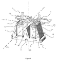
- the figure 1 represents an electromagnetic motor assembly used in multipolar contactors.
- This assembly consists of a coil (4) inserted in a support carcass (3) itself embedded in a fixed ferromagnetic armature (1) cooperating with a movable ferromagnetic armature (2).
- the two plates (1, 2) are spaced apart from each other by an air gap (E), the motor assembly being in the open position.
- the supporting carcass (3) is composed of a central shaft (20) around which is fixed the coil (4), an upper part (21) facing the movable armature (2) and a part lower (22) bearing on the fixed armature (1).
- the fixed armature (1) must be positioned exactly in front of the mobile armature (2) so as to keep a gap (E) constant.
- the armatures (1, 2) have a specific geometry.
- the fixed armature is composed of a base (7) from which three arms (8, 9, 10) extend, two of them (8, 10) being located at the ends of the base (7). ), the other (9) being central.
- the moving armature is also composed of a base (11) from which four branches (12, 13, 14, 15) extend, including two end limbs (12, 15) and two central limbs (13, 14) looking like a fork.
- All the branches (8, 9, 10, 12, 13, 14, 15) are pointed, providing polar surfaces (5, 6) inclined at the same angle with respect to the direction of travel (D) of the mobile armature (2).
- the surfaces (5, 6) of the branches (8, 9, 10, 12, 13, 14, 15) of the fixed (1) and movable (2) armatures facing each other, in other words the surfaces polar, are inclined at the same angle relative to the bases (7, 11), and the surfaces of the branches (8, 9, 10, 12, 13, 14, 15) of the fixed (1) and movable (2) armatures no vis-à-vis are perpendicular to the bases (7, 11).
- the figure 2 represents the motor assembly as described above, in the closed position.
- the movable armature (2) is attracted by the fixed armature (1) and approaches it to a gap (e).
- the fixed armature (1) is provided with a recess connection of the support casing (3).
- This embedding connection consists of deformable tabs (16) extending the tips of the end branches (10, 8) of the fixed armature (1).
- the fixed armature (1) is composed of a plurality of identical sheets of ferromagnetic material. Each sheet has the appearance of the geometric shape of the fixed armature (1). The sheets are stacked in a row, reproducing the volume of the fixed armature (2).
- Said sheets having an unciform extension are distributed in the fixed armature (1) so as to balance the support points with the support frame (3). Indeed, so that the latter (3) is properly maintained in the fixed armature (1), and this at all points, it is necessary that it is properly positioned in the fixed armature (1) as will be explained more far in the description, and then that there are several points of attachment between the two parts (3, 1), preferably four points of attachment distributed at the four ends of the assembly formed by the carcass (3) and the fixed armature (1).
- these attachment points consist for example of at least two tabs (16) on two sheets placed respectively at the beginning and at the end of the row of metal plates constituting the fixed armature (1).
- At least two adjacent sheets located at the ends of the frame (1) are provided with tabs (16).
- the overall result is a fixed armature (1) provided with four pairs of legs (16) adapted to be folded down on the support carcass (3) in accordance with the figure 4 .
- Each lug (16) of the fixed armature (1) is uniform, its base being deformable so as to crimp the upper part (21) of the support carcass (3) by folding each of the lugs (16) of s' press on the upper part (21) of the supporting frame (3).
- the support frame (3) is plugged into the central branch (9) of the fixed armature (1) along a mounting axis (X).
- This mounting axis (X) is also an axis of symmetry common to the two parts (1, 3).
- the lower part (22) of the supporting carcass (3) rests on a flat surface (23) of the base (7) of the fixed armature (1) in a bearing direction parallel to the mounting axis ( X).
- the positioning of the carcass (3) in the fixed armature (1) along the axis (Y) as shown in FIG. figure 4 , perpendicular to the axes (X) and (Z), is less important because the operation of the motor is not sensitive in the direction of this axis (Y).
- the thickness of the plates constituting the reinforcements being variable, it is all the more difficult to accurately position the carcass (3) in the armature (1) along this axis (Y).
- a groove (17) is present on the underside of the base (7) of the fixed armature (1) along its transverse axis of symmetry.
- This groove (17) coincides with a projection on the base of the crimping jig, and then allows the centering of the fixed armature (1) on the jig along the axis (Z).
Landscapes
- Physics & Mathematics (AREA)
- Electromagnetism (AREA)
- Manufacture Of Motors, Generators (AREA)
Priority Applications (1)
| Application Number | Priority Date | Filing Date | Title |
|---|---|---|---|
| EP20100306065 EP2437278B1 (de) | 2010-09-30 | 2010-09-30 | Zusammenbau eines Motors eines mehrpoligen Schutzschalters |
Applications Claiming Priority (1)
| Application Number | Priority Date | Filing Date | Title |
|---|---|---|---|
| EP20100306065 EP2437278B1 (de) | 2010-09-30 | 2010-09-30 | Zusammenbau eines Motors eines mehrpoligen Schutzschalters |
Publications (2)
| Publication Number | Publication Date |
|---|---|
| EP2437278A1 true EP2437278A1 (de) | 2012-04-04 |
| EP2437278B1 EP2437278B1 (de) | 2013-05-15 |
Family
ID=43602970
Family Applications (1)
| Application Number | Title | Priority Date | Filing Date |
|---|---|---|---|
| EP20100306065 Active EP2437278B1 (de) | 2010-09-30 | 2010-09-30 | Zusammenbau eines Motors eines mehrpoligen Schutzschalters |
Country Status (1)
| Country | Link |
|---|---|
| EP (1) | EP2437278B1 (de) |
Citations (6)
| Publication number | Priority date | Publication date | Assignee | Title |
|---|---|---|---|---|
| DE7103106U (de) * | 1971-01-28 | 1972-07-06 | Siemens Ag | Elektromagnetisches Schaltgerät |
| JPS5469344U (de) * | 1977-10-26 | 1979-05-17 | ||
| FR2406885A1 (fr) * | 1977-10-18 | 1979-05-18 | Telemecanique Electrique | Electro-aimant pour contacteur alimente en courant continu |
| DE3733895A1 (de) * | 1987-10-07 | 1989-04-27 | Asea Brown Boveri | Elektrisches schaltgeraet mit einem elektromagnetischen schalterantrieb |
| EP1978536A1 (de) * | 2007-03-28 | 2008-10-08 | Siemens Aktiengesellschaft | Elektromechanisches Schaltgerät |
| WO2009131015A1 (ja) * | 2008-04-24 | 2009-10-29 | パナソニック電工株式会社 | リレー用電磁石 |
-
2010
- 2010-09-30 EP EP20100306065 patent/EP2437278B1/de active Active
Patent Citations (6)
| Publication number | Priority date | Publication date | Assignee | Title |
|---|---|---|---|---|
| DE7103106U (de) * | 1971-01-28 | 1972-07-06 | Siemens Ag | Elektromagnetisches Schaltgerät |
| FR2406885A1 (fr) * | 1977-10-18 | 1979-05-18 | Telemecanique Electrique | Electro-aimant pour contacteur alimente en courant continu |
| JPS5469344U (de) * | 1977-10-26 | 1979-05-17 | ||
| DE3733895A1 (de) * | 1987-10-07 | 1989-04-27 | Asea Brown Boveri | Elektrisches schaltgeraet mit einem elektromagnetischen schalterantrieb |
| EP1978536A1 (de) * | 2007-03-28 | 2008-10-08 | Siemens Aktiengesellschaft | Elektromechanisches Schaltgerät |
| WO2009131015A1 (ja) * | 2008-04-24 | 2009-10-29 | パナソニック電工株式会社 | リレー用電磁石 |
Also Published As
| Publication number | Publication date |
|---|---|
| EP2437278B1 (de) | 2013-05-15 |
Similar Documents
| Publication | Publication Date | Title |
|---|---|---|
| EP3547001B1 (de) | Optische vorrichtung für fahrzeuge mit heizelement | |
| EP2628213B1 (de) | Elektrische steckverbinderanordnung | |
| EP0038745A1 (de) | Anordnung mit einer Kontaktklemme und mit einem mit dieser Klemme zusammenwirkenden Stecker zum unterbrechungsfreien Verbinden mit einem die Klemme tragenden Schaltkreis | |
| FR2897717A1 (fr) | Commutateur electromagnetique ayant un noyau magnetique fixe comportant une partie de disque formee d'un empilement de feuilles metalliques de base et d'equilibrage. | |
| FR2640083A1 (fr) | Support pour ligne de transmission hyperfrequence, notamment du type triplaque | |
| EP3544120B1 (de) | Elektrogerät und erdungsverfahren für ein solches gerät | |
| FR2541815A1 (fr) | Relais electromagnetique a armature articulee | |
| FR2520152A1 (fr) | Electro-aimant a equipage mobile a aimant permanent a fonctionnement monostable | |
| EP0174238A2 (de) | Monostabil oder bistabil arbeitender polarisierter Elektromagnet | |
| FR2604293A1 (fr) | Dispositif electromagnetique de commande de l'alimentation en courant du demarreur electrique d'un moteur a combustion interne | |
| FR2566571A1 (fr) | Dispositif amortiseur de surtensions pour electroaimant et electroaimant equipe d'un tel dispositif | |
| EP2437278B1 (de) | Zusammenbau eines Motors eines mehrpoligen Schutzschalters | |
| EP1867009B1 (de) | Klemmeinrichtung für einen verbindungsanschluss | |
| WO2013144466A1 (fr) | Coque pour téléphone mobile et terminal mobile | |
| FR2888395A1 (fr) | Commutateur electrique miniaturise du type normalement ferme | |
| EP1424756A1 (de) | Elektrische Verbindungsanordnung eines electrischen Apparates mit einem modularen Verbindungskamm oder ähnlich | |
| EP0033817A1 (de) | Elektromagnetisches Relais mit zwei synchronisierten Ankern | |
| FR2596577A1 (fr) | Declencheur polarise | |
| EP0693765B1 (de) | Elektromagnetischer Auslöser für einen Niederspannungsschutzschalter | |
| FR2813988A1 (fr) | Dispositif de coupure d'un appareil interrupteur | |
| EP1925011B1 (de) | Wärmekraftmaschinenanlasserschalter mit verbesserten elektrischen verbindungsmitteln der wicklung | |
| FR2897469A1 (fr) | Dispositif de commutation electrique aux contacts electriques renforces | |
| FR2722609A1 (fr) | Disjoncteur electrique a actionneur electromagnetique pour calibres eleves | |
| FR2897992A1 (fr) | Dispositif d'assemblage pour moteur electrique. | |
| FR2959069A1 (fr) | Douille a double verrouillage pour ampoule electrique |
Legal Events
| Date | Code | Title | Description |
|---|---|---|---|
| PUAI | Public reference made under article 153(3) epc to a published international application that has entered the european phase |
Free format text: ORIGINAL CODE: 0009012 |
|
| AK | Designated contracting states |
Kind code of ref document: A1 Designated state(s): AL AT BE BG CH CY CZ DE DK EE ES FI FR GB GR HR HU IE IS IT LI LT LU LV MC MK MT NL NO PL PT RO SE SI SK SM TR |
|
| AX | Request for extension of the european patent |
Extension state: BA ME RS |
|
| 17P | Request for examination filed |
Effective date: 20120927 |
|
| RIC1 | Information provided on ipc code assigned before grant |
Ipc: H01H 50/04 20060101AFI20121026BHEP |
|
| GRAP | Despatch of communication of intention to grant a patent |
Free format text: ORIGINAL CODE: EPIDOSNIGR1 |
|
| GRAS | Grant fee paid |
Free format text: ORIGINAL CODE: EPIDOSNIGR3 |
|
| GRAA | (expected) grant |
Free format text: ORIGINAL CODE: 0009210 |
|
| AK | Designated contracting states |
Kind code of ref document: B1 Designated state(s): AL AT BE BG CH CY CZ DE DK EE ES FI FR GB GR HR HU IE IS IT LI LT LU LV MC MK MT NL NO PL PT RO SE SI SK SM TR |
|
| REG | Reference to a national code |
Ref country code: CH Ref legal event code: EP Ref country code: GB Ref legal event code: FG4D Free format text: NOT ENGLISH |
|
| REG | Reference to a national code |
Ref country code: AT Ref legal event code: REF Ref document number: 612507 Country of ref document: AT Kind code of ref document: T Effective date: 20130615 |
|
| REG | Reference to a national code |
Ref country code: IE Ref legal event code: FG4D Free format text: LANGUAGE OF EP DOCUMENT: FRENCH |
|
| REG | Reference to a national code |
Ref country code: DE Ref legal event code: R096 Ref document number: 602010007089 Country of ref document: DE Effective date: 20130718 |
|
| REG | Reference to a national code |
Ref country code: AT Ref legal event code: MK05 Ref document number: 612507 Country of ref document: AT Kind code of ref document: T Effective date: 20130515 |
|
| REG | Reference to a national code |
Ref country code: LT Ref legal event code: MG4D |
|
| REG | Reference to a national code |
Ref country code: NL Ref legal event code: VDEP Effective date: 20130515 |
|
| PG25 | Lapsed in a contracting state [announced via postgrant information from national office to epo] |
Ref country code: AT Free format text: LAPSE BECAUSE OF FAILURE TO SUBMIT A TRANSLATION OF THE DESCRIPTION OR TO PAY THE FEE WITHIN THE PRESCRIBED TIME-LIMIT Effective date: 20130515 Ref country code: IS Free format text: LAPSE BECAUSE OF FAILURE TO SUBMIT A TRANSLATION OF THE DESCRIPTION OR TO PAY THE FEE WITHIN THE PRESCRIBED TIME-LIMIT Effective date: 20130915 Ref country code: NO Free format text: LAPSE BECAUSE OF FAILURE TO SUBMIT A TRANSLATION OF THE DESCRIPTION OR TO PAY THE FEE WITHIN THE PRESCRIBED TIME-LIMIT Effective date: 20130815 Ref country code: ES Free format text: LAPSE BECAUSE OF FAILURE TO SUBMIT A TRANSLATION OF THE DESCRIPTION OR TO PAY THE FEE WITHIN THE PRESCRIBED TIME-LIMIT Effective date: 20130826 Ref country code: PT Free format text: LAPSE BECAUSE OF FAILURE TO SUBMIT A TRANSLATION OF THE DESCRIPTION OR TO PAY THE FEE WITHIN THE PRESCRIBED TIME-LIMIT Effective date: 20130916 Ref country code: SE Free format text: LAPSE BECAUSE OF FAILURE TO SUBMIT A TRANSLATION OF THE DESCRIPTION OR TO PAY THE FEE WITHIN THE PRESCRIBED TIME-LIMIT Effective date: 20130515 Ref country code: SI Free format text: LAPSE BECAUSE OF FAILURE TO SUBMIT A TRANSLATION OF THE DESCRIPTION OR TO PAY THE FEE WITHIN THE PRESCRIBED TIME-LIMIT Effective date: 20130515 Ref country code: GR Free format text: LAPSE BECAUSE OF FAILURE TO SUBMIT A TRANSLATION OF THE DESCRIPTION OR TO PAY THE FEE WITHIN THE PRESCRIBED TIME-LIMIT Effective date: 20130816 Ref country code: FI Free format text: LAPSE BECAUSE OF FAILURE TO SUBMIT A TRANSLATION OF THE DESCRIPTION OR TO PAY THE FEE WITHIN THE PRESCRIBED TIME-LIMIT Effective date: 20130515 Ref country code: LT Free format text: LAPSE BECAUSE OF FAILURE TO SUBMIT A TRANSLATION OF THE DESCRIPTION OR TO PAY THE FEE WITHIN THE PRESCRIBED TIME-LIMIT Effective date: 20130515 |
|
| PG25 | Lapsed in a contracting state [announced via postgrant information from national office to epo] |
Ref country code: PL Free format text: LAPSE BECAUSE OF FAILURE TO SUBMIT A TRANSLATION OF THE DESCRIPTION OR TO PAY THE FEE WITHIN THE PRESCRIBED TIME-LIMIT Effective date: 20130515 Ref country code: BG Free format text: LAPSE BECAUSE OF FAILURE TO SUBMIT A TRANSLATION OF THE DESCRIPTION OR TO PAY THE FEE WITHIN THE PRESCRIBED TIME-LIMIT Effective date: 20130815 Ref country code: HR Free format text: LAPSE BECAUSE OF FAILURE TO SUBMIT A TRANSLATION OF THE DESCRIPTION OR TO PAY THE FEE WITHIN THE PRESCRIBED TIME-LIMIT Effective date: 20130515 |
|
| PG25 | Lapsed in a contracting state [announced via postgrant information from national office to epo] |
Ref country code: LV Free format text: LAPSE BECAUSE OF FAILURE TO SUBMIT A TRANSLATION OF THE DESCRIPTION OR TO PAY THE FEE WITHIN THE PRESCRIBED TIME-LIMIT Effective date: 20130515 |
|
| PG25 | Lapsed in a contracting state [announced via postgrant information from national office to epo] |
Ref country code: CZ Free format text: LAPSE BECAUSE OF FAILURE TO SUBMIT A TRANSLATION OF THE DESCRIPTION OR TO PAY THE FEE WITHIN THE PRESCRIBED TIME-LIMIT Effective date: 20130515 Ref country code: DK Free format text: LAPSE BECAUSE OF FAILURE TO SUBMIT A TRANSLATION OF THE DESCRIPTION OR TO PAY THE FEE WITHIN THE PRESCRIBED TIME-LIMIT Effective date: 20130515 Ref country code: EE Free format text: LAPSE BECAUSE OF FAILURE TO SUBMIT A TRANSLATION OF THE DESCRIPTION OR TO PAY THE FEE WITHIN THE PRESCRIBED TIME-LIMIT Effective date: 20130515 Ref country code: SK Free format text: LAPSE BECAUSE OF FAILURE TO SUBMIT A TRANSLATION OF THE DESCRIPTION OR TO PAY THE FEE WITHIN THE PRESCRIBED TIME-LIMIT Effective date: 20130515 |
|
| PG25 | Lapsed in a contracting state [announced via postgrant information from national office to epo] |
Ref country code: NL Free format text: LAPSE BECAUSE OF FAILURE TO SUBMIT A TRANSLATION OF THE DESCRIPTION OR TO PAY THE FEE WITHIN THE PRESCRIBED TIME-LIMIT Effective date: 20130515 Ref country code: RO Free format text: LAPSE BECAUSE OF FAILURE TO SUBMIT A TRANSLATION OF THE DESCRIPTION OR TO PAY THE FEE WITHIN THE PRESCRIBED TIME-LIMIT Effective date: 20130515 Ref country code: IT Free format text: LAPSE BECAUSE OF FAILURE TO SUBMIT A TRANSLATION OF THE DESCRIPTION OR TO PAY THE FEE WITHIN THE PRESCRIBED TIME-LIMIT Effective date: 20130515 |
|
| PLBE | No opposition filed within time limit |
Free format text: ORIGINAL CODE: 0009261 |
|
| STAA | Information on the status of an ep patent application or granted ep patent |
Free format text: STATUS: NO OPPOSITION FILED WITHIN TIME LIMIT |
|
| BERE | Be: lapsed |
Owner name: HAGER-ELECTRO SAS Effective date: 20130930 |
|
| 26N | No opposition filed |
Effective date: 20140218 |
|
| PG25 | Lapsed in a contracting state [announced via postgrant information from national office to epo] |
Ref country code: MC Free format text: LAPSE BECAUSE OF FAILURE TO SUBMIT A TRANSLATION OF THE DESCRIPTION OR TO PAY THE FEE WITHIN THE PRESCRIBED TIME-LIMIT Effective date: 20130515 |
|
| REG | Reference to a national code |
Ref country code: DE Ref legal event code: R097 Ref document number: 602010007089 Country of ref document: DE Effective date: 20140218 |
|
| REG | Reference to a national code |
Ref country code: IE Ref legal event code: MM4A |
|
| PG25 | Lapsed in a contracting state [announced via postgrant information from national office to epo] |
Ref country code: BE Free format text: LAPSE BECAUSE OF NON-PAYMENT OF DUE FEES Effective date: 20130930 Ref country code: IE Free format text: LAPSE BECAUSE OF NON-PAYMENT OF DUE FEES Effective date: 20130930 |
|
| REG | Reference to a national code |
Ref country code: CH Ref legal event code: NV Representative=s name: RENTSCH PARTNER AG, CH |
|
| GBPC | Gb: european patent ceased through non-payment of renewal fee |
Effective date: 20140930 |
|
| PG25 | Lapsed in a contracting state [announced via postgrant information from national office to epo] |
Ref country code: SM Free format text: LAPSE BECAUSE OF FAILURE TO SUBMIT A TRANSLATION OF THE DESCRIPTION OR TO PAY THE FEE WITHIN THE PRESCRIBED TIME-LIMIT Effective date: 20130515 |
|
| PG25 | Lapsed in a contracting state [announced via postgrant information from national office to epo] |
Ref country code: CY Free format text: LAPSE BECAUSE OF FAILURE TO SUBMIT A TRANSLATION OF THE DESCRIPTION OR TO PAY THE FEE WITHIN THE PRESCRIBED TIME-LIMIT Effective date: 20130515 Ref country code: MT Free format text: LAPSE BECAUSE OF FAILURE TO SUBMIT A TRANSLATION OF THE DESCRIPTION OR TO PAY THE FEE WITHIN THE PRESCRIBED TIME-LIMIT Effective date: 20130515 Ref country code: TR Free format text: LAPSE BECAUSE OF FAILURE TO SUBMIT A TRANSLATION OF THE DESCRIPTION OR TO PAY THE FEE WITHIN THE PRESCRIBED TIME-LIMIT Effective date: 20130515 |
|
| PG25 | Lapsed in a contracting state [announced via postgrant information from national office to epo] |
Ref country code: HU Free format text: LAPSE BECAUSE OF FAILURE TO SUBMIT A TRANSLATION OF THE DESCRIPTION OR TO PAY THE FEE WITHIN THE PRESCRIBED TIME-LIMIT; INVALID AB INITIO Effective date: 20100930 Ref country code: MK Free format text: LAPSE BECAUSE OF FAILURE TO SUBMIT A TRANSLATION OF THE DESCRIPTION OR TO PAY THE FEE WITHIN THE PRESCRIBED TIME-LIMIT Effective date: 20130515 Ref country code: LU Free format text: LAPSE BECAUSE OF NON-PAYMENT OF DUE FEES Effective date: 20130930 Ref country code: GB Free format text: LAPSE BECAUSE OF NON-PAYMENT OF DUE FEES Effective date: 20140930 |
|
| REG | Reference to a national code |
Ref country code: FR Ref legal event code: PLFP Year of fee payment: 7 |
|
| REG | Reference to a national code |
Ref country code: FR Ref legal event code: PLFP Year of fee payment: 8 |
|
| REG | Reference to a national code |
Ref country code: CH Ref legal event code: PCAR Free format text: NEW ADDRESS: BELLERIVESTRASSE 203 POSTFACH, 8034 ZUERICH (CH) |
|
| REG | Reference to a national code |
Ref country code: FR Ref legal event code: PLFP Year of fee payment: 9 |
|
| PG25 | Lapsed in a contracting state [announced via postgrant information from national office to epo] |
Ref country code: AL Free format text: LAPSE BECAUSE OF FAILURE TO SUBMIT A TRANSLATION OF THE DESCRIPTION OR TO PAY THE FEE WITHIN THE PRESCRIBED TIME-LIMIT Effective date: 20130515 |
|
| P01 | Opt-out of the competence of the unified patent court (upc) registered |
Effective date: 20230606 |
|
| PGFP | Annual fee paid to national office [announced via postgrant information from national office to epo] |
Ref country code: DE Payment date: 20240927 Year of fee payment: 15 |
|
| PGFP | Annual fee paid to national office [announced via postgrant information from national office to epo] |
Ref country code: FR Payment date: 20240925 Year of fee payment: 15 |
|
| PGFP | Annual fee paid to national office [announced via postgrant information from national office to epo] |
Ref country code: CH Payment date: 20241002 Year of fee payment: 15 |