EP2437312A1 - Boîte à bornes, agencement de connexion de câble de sortie pour boîte à bornes de module de cellules solaires et fixation d'agencement pour le câble de sortie - Google Patents
Boîte à bornes, agencement de connexion de câble de sortie pour boîte à bornes de module de cellules solaires et fixation d'agencement pour le câble de sortie Download PDFInfo
- Publication number
- EP2437312A1 EP2437312A1 EP11007708A EP11007708A EP2437312A1 EP 2437312 A1 EP2437312 A1 EP 2437312A1 EP 11007708 A EP11007708 A EP 11007708A EP 11007708 A EP11007708 A EP 11007708A EP 2437312 A1 EP2437312 A1 EP 2437312A1
- Authority
- EP
- European Patent Office
- Prior art keywords
- output cable
- terminal box
- cable
- terminal
- solar cell
- Prior art date
- Legal status (The legal status is an assumption and is not a legal conclusion. Google has not performed a legal analysis and makes no representation as to the accuracy of the status listed.)
- Granted
Links
- 239000011248 coating agent Substances 0.000 claims abstract description 73
- 238000000576 coating method Methods 0.000 claims abstract description 73
- 238000003780 insertion Methods 0.000 claims abstract description 66
- 230000037431 insertion Effects 0.000 claims abstract description 66
- 230000002093 peripheral effect Effects 0.000 claims abstract description 13
- 238000007789 sealing Methods 0.000 claims description 32
- 239000002184 metal Substances 0.000 claims description 7
- 238000006073 displacement reaction Methods 0.000 description 12
- 239000000463 material Substances 0.000 description 11
- 230000000717 retained effect Effects 0.000 description 10
- 239000011247 coating layer Substances 0.000 description 9
- 229920005989 resin Polymers 0.000 description 8
- 239000011347 resin Substances 0.000 description 8
- 238000010276 construction Methods 0.000 description 7
- XLYOFNOQVPJJNP-UHFFFAOYSA-N water Substances O XLYOFNOQVPJJNP-UHFFFAOYSA-N 0.000 description 7
- 230000035882 stress Effects 0.000 description 5
- 230000032683 aging Effects 0.000 description 4
- 230000015556 catabolic process Effects 0.000 description 4
- 238000006731 degradation reaction Methods 0.000 description 4
- 230000006866 deterioration Effects 0.000 description 4
- 230000000694 effects Effects 0.000 description 3
- 238000005476 soldering Methods 0.000 description 3
- 230000015572 biosynthetic process Effects 0.000 description 2
- 230000006735 deficit Effects 0.000 description 2
- 239000013013 elastic material Substances 0.000 description 2
- 238000003754 machining Methods 0.000 description 2
- 239000003566 sealing material Substances 0.000 description 2
- 238000004804 winding Methods 0.000 description 2
- 239000004698 Polyethylene Substances 0.000 description 1
- BZHJMEDXRYGGRV-UHFFFAOYSA-N Vinyl chloride Chemical compound ClC=C BZHJMEDXRYGGRV-UHFFFAOYSA-N 0.000 description 1
- 230000002411 adverse Effects 0.000 description 1
- 238000005452 bending Methods 0.000 description 1
- 230000008602 contraction Effects 0.000 description 1
- 229920003020 cross-linked polyethylene Polymers 0.000 description 1
- 239000004703 cross-linked polyethylene Substances 0.000 description 1
- 238000007667 floating Methods 0.000 description 1
- 230000001771 impaired effect Effects 0.000 description 1
- 239000011159 matrix material Substances 0.000 description 1
- 239000007769 metal material Substances 0.000 description 1
- 238000012986 modification Methods 0.000 description 1
- 230000004048 modification Effects 0.000 description 1
- 229920000573 polyethylene Polymers 0.000 description 1
- 229920000098 polyolefin Polymers 0.000 description 1
- 229920001296 polysiloxane Polymers 0.000 description 1
- 239000011148 porous material Substances 0.000 description 1
- 238000010248 power generation Methods 0.000 description 1
- 229920003002 synthetic resin Polymers 0.000 description 1
- 239000000057 synthetic resin Substances 0.000 description 1
Images




Classifications
-
- H—ELECTRICITY
- H02—GENERATION; CONVERSION OR DISTRIBUTION OF ELECTRIC POWER
- H02S—GENERATION OF ELECTRIC POWER BY CONVERSION OF INFRARED RADIATION, VISIBLE LIGHT OR ULTRAVIOLET LIGHT, e.g. USING PHOTOVOLTAIC [PV] MODULES
- H02S40/00—Components or accessories in combination with PV modules, not provided for in groups H02S10/00 - H02S30/00
- H02S40/30—Electrical components
- H02S40/34—Electrical components comprising specially adapted electrical connection means to be structurally associated with the PV module, e.g. junction boxes
-
- Y—GENERAL TAGGING OF NEW TECHNOLOGICAL DEVELOPMENTS; GENERAL TAGGING OF CROSS-SECTIONAL TECHNOLOGIES SPANNING OVER SEVERAL SECTIONS OF THE IPC; TECHNICAL SUBJECTS COVERED BY FORMER USPC CROSS-REFERENCE ART COLLECTIONS [XRACs] AND DIGESTS
- Y02—TECHNOLOGIES OR APPLICATIONS FOR MITIGATION OR ADAPTATION AGAINST CLIMATE CHANGE
- Y02E—REDUCTION OF GREENHOUSE GAS [GHG] EMISSIONS, RELATED TO ENERGY GENERATION, TRANSMISSION OR DISTRIBUTION
- Y02E10/00—Energy generation through renewable energy sources
- Y02E10/50—Photovoltaic [PV] energy
Definitions
- the present invention relates to a terminal box including a box body attachable to an attachment target, a plurality of terminal plates juxtaposed under a mutually isolated state inside the box body, and a diode conductively connected to and between adjacent terminal plates.
- the invention relates also to an output cable connection arrangement for a solar cell module terminal box for electrically connecting an output cable to a terminal plate provided inside the terminal box to be electrically connected to a solar cell module through a cable insertion portion provided in the terminal box from the outside of the terminal box.
- the invention further relates to a fixation arrangement for the output cable.
- a terminal box of this type a plurality of terminal plates formed respectively of a rectangular metal terminal plate body are fixed in spaced relationship inside a box body formed of a synthetic resin and a diode arranged between adjacent terminal plates has its lead terminal portion rigidly attached by means of soldering to a portion of te surface of the terminal plate body (see e.g. Patent Document 1). That is, the terminal plates and the diode are rigidly unified. Further, after the diode is conductively connected to the terminal plates, sometimes, sealing of the space of the box body is sometimes effected with charging of a sealing material such as silicone.
- the terminal box in case this box is used for an attachment target subjected to severe temperature environment such as a solar cell module, the terminal box per se is also subjected to violent change of the ambient temperature.
- the terminal box comprises an assembly of materials having differing characteristics (especially, thermal expansion coefficients) for forming the terminal plate body, the diode, the sealing material, etc. Therefore, there is the risk of these materials being subjected repeatedly to thermal deformations at different ratios (thermal expansion and thermal contraction) in association with changes in the ambient temperature.
- small differences among the thermal deformation amounts of the respective materials are applied repeatedly as a concentrated load to the connecting portions between the diode and the terminal plate body, so that a connection failure may occur.
- a solar power generation system is configured to generate and supply power with a plurality of solar cell modules disposed in a matrix pattern on e.g. a roof of a building.
- each solar cell module is connected in series or in parallel with an adjacently disposed solar cell module.
- a terminal box is attached to the rear face of the solar cell module. Inside this terminal box, there are provided a plurality of terminal plates to be electrically connected to output terminals of the solar cell modules. Each terminal plate is electrically connected to one end of an output cable for external connection.
- the waterproof sleeve used for fixing the output cable to the cable insertion portion is disposed in such a manner as to surround the outer coating portion of this output cable.
- this outer coating portion tends to be become brittle due to aging degradation as a result of its direct exposure to an outside environment such as ultraviolet rays, a crack may develop therein or its outer shape may be changed or deformed due to frictional wear. If such problem occurs at the contact portion between the outer coating portion and the waterproof sleeve, this may lead to formation of a gap between the outer coating portion and the waterproof sleeve, thus leading to deterioration in the water proof performance of this waterproof sleeve.
- a cable fastener for fasting or fixing the output cable to the terminal box.
- This cable fastener is comprised of a cable pressing member and the cable fastener prevents floating detachment of the output cable through its surface contact with the output cable.
- This cable pressing member is retained and fixed to the terminal box (see e.g. Patent Document 3).
- the first object of the present invention is to provide a terminal box which can effectively resist occurrence of connection failure even when there is a significant temperature difference in the environment where the box is installed.
- the second object of the present invention is to provide a connection arrangement for an output cable of a solar cell module terminal box, which connection arrangement is capable of reliably maintaining its initial waterproof performance.
- the third object of the present invention is to provide a fixation arrangement for an output cable of a solar cell module terminal box, which fixation arrangement is capable of effectively resisting impairment of electric connection between the output cable and the terminal plate.
- the terminal box comprises:
- the displacement-allowing connecting portion can be an arrangement of smaller width (or the thickness or both the width and the thickness) than the terminal plate body or the fixed attachment portion or an arrangement of using a material which can be deformed more easily than the other portion.
- said terminal plate is formed of a metal plate
- said displacement-allowing connecting portion is formed of a bridge portion having a smaller width than the terminal plate body and the fixed attachment portion.
- the displacement-allowing connecting portion is provided as a component having a smaller width than the terminal plate body and the fixed attachment portion, this arrangement is advantageous in that it requires less machining trouble and is economical than the arrangement of forming the bridge portion of a material that can be deformed more easily than the other portion.
- the bridge portion can be a portion which linearly interconnects between the terminal plate body and the fixed attachment portion, or it can be freely designed such as a bridge portion comprising a curved portion or combination of a curved portion and a straight portion.
- said bridge portion includes a curved portion which is bent in the thickness direction.
- the bridge portion can be readily displaced in the thickness direction as well. Therefore, it becomes possible to allow the displacement between the fixed attachment portion and the terminal plate body in any desired direction, such as the width direction, the thickness direction and the length direction of the bridge portion. Hence, even higher displacement allowing effect can be achieved.
- an output cable connection arrangement for a solar cell module terminal box for electrically connecting an output cable to a terminal plate provided inside the terminal box to be electrically connected to a solar cell module through a cable insertion portion provided in the terminal box from the outside of the terminal box, according to the first characterizing feature thereof, said output cable is inserted to said cable insertion portion such that a waterproof portion which covers an outer peripheral face and an end face of a leading end of an inner coating portion coating a core wire of said output cable and an outer coating portion coating said inner coating portion adjacent the waterproof portion are engaged within said cable insertion portion.
- the output cable there is widely employed a cable configured such that its core wire is coated by the inner coating portion and this inner coating portion is coated by the outer coating portion.
- the outer coating portion depending on the material constituting it, there is a risk of developing a crack therein or change in its outer shape, due to aging degradation, which would be a cause for deterioration in the waterproof performance.
- the waterproof portion instead of the outer coating portion, surrounds the outer peripheral face of the leading end of the inner coating portion. The inner coating portion, as being surrounded by the waterproof portion and the outer coating portion, is not directly exposed to the outside environment.
- the waterproof portion is configured to surround the end face of the inner coating portion, when e.g. the output cable is inserted into the cable insertion portion from the side of the waterproof portion, with the waterproof portion being kept attached to the output cable, it is possible to prevent roll-up of the waterproof portion due to the frictional resistance relative to the cable insertion portion. Therefore, the operation of inserting the output cable into the cable insertion portion can be carried out speedily.
- the waterproof portion is disposed at the leading end of the output cable to be adjacent to the outer coating portion, it is possible to dispose the waterproof portion and the outer coating portion continuously, so that water-tightness between the waterproof portion and the outer coating portion can be maintained.
- the waterproof performance can be improved with disposing the waterproof portion at the leading end of the output cable, without having to change the material forming the outer coating portion and the material forming the inner coating portion of the widely used conventional output cable.
- annular sealing member is provided on at least one of an outer surface and an inner surface of said waterproof portion.
- the annular sealing member when the annular sealing member is provided on the outer surface of the waterproof portion and this sealing member is held between the waterproof portion and the cable insertion portion, it becomes possible to reliably prevent intrusion of water to the interior of the terminal box from the outside via the gap between the waterproof portion and the cable insertion portion.
- the annular sealing member when the annular sealing member is provided on the inner surface of the waterproof portion and this sealing member is held between the waterproof portion and the inner coating portion, it becomes possible to reliably prevent intrusion of water to the interior of the terminal box from the outside via the gap between the waterproof portion and the inner coating portion. In this way, with disposing of the annular sealing member in the manners described above, the waterproof performance after the connection of the output cable can be improved.
- said cable insertion portion forms an annular recess corresponding to the sealing member provided on the outer surface of said waterproof portion.
- the sealing member can be engaged within the annular recess with this sealing member provided on the outer surface of the waterproof portion being in gapless contact with the recess.
- the area of gapless contact between the sealing member and the recess can be increased by an amount corresponding to the recess concavely formed.
- the waterproof performance after the connection of the output cable can be even further improved.
- an output cable fixation arrangement for a solar cell module terminal box for achieving the third object, in an output cable fixation arrangement for a solar cell module terminal box wherein a terminal plate to be electrically connected to a solar cell module is provided inside a terminal box and an output cable electrically connected to the terminal plate is extended to the outside of the terminal box, according to a first characterizing feature, said output cable is fixed to said terminal box, separately from the electric connection thereof, by means of a cable fastener having a first fixing portion to be fixed to a barrel portion of the output cable and a second fixing portion to be fixed to a portion of the terminal box.
- the output cable and the terminal box can be fixed integral with each other via the cable fastener. Hence, displacement of the output cable relative to the terminal box can be restricted for an extended period of time. Therefore, with this arrangement, the risk of impairment of the electric connection between the output cable and the terminal plate can be further restricted.
- said first fixing portion is formed like a band portion that can be wound and held around said barrel portion and said second fixing portion is formed as a T-like projection from said first fixing portion to be wound and held about the terminal box.
- the output cable and the terminal box can be fixed integrally via the cable fastener.
- said first fixing portion forms a linear projection capable of applying a concentrated load to the outer face of said barrel portion.
- said terminal box forms a cable holding portion cable of allowing insertion of said second fixing portion of the output cable to which said cable fastener is attached and capable also of holding/surrounding an area extending at least half a perimeter of the portion to which said first fixing portion is fixed or adjacent said first fixing portion.
- the second fixing portion being oriented toward the connection side for the terminal plate of the output cable, it is possible to surround an area extending for at least half the perimeter of the portion to which the first fixing portion is fixed of the output cable with the cable fastener is fastened or the portion of the output cable adjacent the first fixing portion. Therefore, the fixation posture of the output cable relative to the terminal box can be readily maintained for an extended period of time so that the electric connection of the output cable relative to the terminal plate will not be impaired.
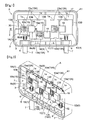
- Fig. 1 and Fig. 2 show a terminal box A of a solar cell module (an example of "attachment target").
- the terminal box A includes a box body A1 formed of resin and provided in the form of a rectangular box mounting therein four terminal plates 1 to be electrically connected to the solar cell modules (not shown) and a lid member (not shown) formed of resin and configured to close an opening 2 of the box body A1.
- a bottom plate 3 of the box body A1 there are formed as projections, two kinds of holding portions 13A to which the respective terminal plates 1 are to be retained and holding walls 13B configured to come into contact with the edges of the respective terminal plates 1 and fix the respective terminal plates 1, at positions corresponding to the respective terminal plates 1. Further, the bottom plate 3 defines insertion holes 17 as through holes, for allowing insertion of output terminals (not shown) of the solar cell modules (not shown) to be electrically connected to the respective terminal plates 1.
- One of the holding portions 13A is comprised of a linear-shaped retained portion 13a to which a retaining portion 1a provided on one side of the terminal plate 1 is to retained to be held thereto.
- the other one of the holding portions 13A is comprised of a groove-like engaging portion 13b into which the other side portion of the terminal plate 1 is to be engaged.
- a side plate 5 of the box body A1 defines, at opposed ends thereof, cable insertion holes 6 for allowing insertion of a pair of output cables 7 connected from the terminal plates 1 to e.g. a rechargeable battery or the like, with maintaining waterproof condition.
- Each terminal plate 1 is formed of a conductive metal plate. And, as the plate is clamped and held by the holding portion 13A and the holding wall 13B, the terminal plates 1 are juxtaposed in spaced relationship and in mutually isolated state. Incidentally, adjacent terminal plates 1 are electrically interconnected via a bypass diode (simply “diode” hereinafter) 18.
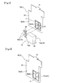
- the diode 18, as shown in Figs. 3 through 5 is provided as a packaged or unitary diode including a diode body 18A formed integral as a rectangular block-like plate member and a lead terminal portion 19.
- the lead terminal portion 19 includes a pair of anode electrodes 19b projecting perpendicularly from one end face of the diode body 18A and a cathode electrode 19a formed integral with and along one end face of the diode body 18A.
- the pair of anode electrodes 19b are provided as metal band-like members juxtaposed with a space therebetween along the width direction.
- the leading end of the anode electrode 19b in the longitudinal direction is fixedly attached by means of soldering to a fixed attachment portion 8 of the terminal plate 1 to be detailed later.
- the intermediate portion of the anode electrode 19b in the longitudinal direction is treated with a forming work to obtain a letter-"J" shape in its vertical section. With provision of this forming-machined portion 35, a relative positional change which may occur between the leading end portion and the base end portion of the anode electrode 19b can be readily absorbed through a flexion deformation.
- the cathode electrode 19a is comprised of a metal rectangular plate provided integral with a portion of the back face portion of the diode body 18A.
- a terminal edge portion of the cathode electrode 19a forms a projecting edge portion 36 projecting by a certain length from the other end face of the diode body 18A.
- This projecting edge portion 36 is fixedly attached by means of soldering to the fixed attachment portion 8 (a cathode side fixed attachment portion 8a to be described later) of the terminal plate 1.
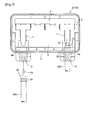
- Each one of the four juxtaposed terminal plates 1 includes a terminal plate body 30 having an approximately rectangular shape, a pair of fixed attachment portions 8 to which the pair of lead terminal portions 19 (the cathode electrode 19a, the anode electrode 19b) of the diode 18 are fixedly attached, and a bridge portion (corresponding to the "displacement allowing connecting portion") 31 for electrically connecting the terminal plate body 30 and the one fixed attachment portion 8 (the anode side fixed attachment portion 8b to which the anode electrode 19b is fixedly attached) with allowing relative displacement therebetween.
- a retaining portion 1a At one side of each terminal plate 1 in the direction normal to the juxtaposing direction, there is provided a retaining portion 1a.
- the cathode side fixed attachment portion 8a to which the cathode electrode 19a is fixedly attached is formed as a portion of the terminal plate body 30 without providing the bridge portion 31 (see Fig. 5 ).
- the first terminal plate 1A and the fourth terminal plate 1D located on the opposed ends respectively include, at the other side thereof, a caulking connection portion 32 for electrically connecting the output cable 7, as shown in Fig. 4 .
- the second terminal plate 1B and the third terminal plate 1C located at the center respectively is configured such that the other side thereof is engaged into an engaging portion 13b (see Fig. 2 ).
- the first terminal plate 1A and the fourth terminal plate 1D are disposed with the opposed edge portions thereof being held by the holding walls 13B of the box body A1 and with the retaining portion 1a of the one side being retained to the retained portion 13a of the box body A1. And, to the caulking connection portion 32, a terminal end of the output cable 7 inserted through the cable insertion portion 6 of the box body A1 is electrically connected by means of calking fixation.
- the second terminal plate 1B and the third terminal plate 1C are disposed with the opposed edge portions thereof being held by the holding walls 13B of the box body A1 and with the other side being engaged in the engaging portion 13b of the box body A1 and also with the retaining portion 1a on the one side being retained to the retained portion 13a of the box body A1.
- the bridge portion 31 and the anode side fixed attachment portion 8b are formed at a portion surrounded by a cutaway zone Z which is formed by cutting away a portion of the terminal plate 1.
- the anode side fixed attachment portion 8b is constituted from a rectangular portion formed in the cutaway zone Z to be spaced from the terminal plate body 30.
- the bridge portions 31 are provided as a pair and constituted from narrow curved portions provided integrally from one longitudinal side of the rectangular anode side fixed attachment portion 8b to the inner peripheral edge portion facing the cutaway zone Z of the terminal body 30.
- the curve shape is set as a letter-J shape (or right/left reversed J shape) as seen in the plan view.
- the bridge portion 31 has a width set be smaller than the fixed attachment portion 8 and terminal plate body 30, so that the bridge portion 31 with the reduced sectional area can absorb the deformation faster than the other portion.
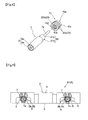
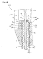
- the invention provides a connection arrangement for an output cable for a solar cell module terminal box to be electrically connected to a plurality of terminal plates 1 provided inside the terminal box A to be electrically connected to a solar cell module (not shown) through a cable insertion portion 6 provided in the terminal box A from the outside of the terminal box A ( Figs. 7-10 ).
- the output cable 7 connection arrangement is used for inserting the output cable 7 into the cable insertion portion 6 with a waterproof portion 10 and an outer coating portion 9b being engaged within the cable insertion portion 6.
- the waterproof portion 10 covers an outer peripheral face 91a and an end face 91b of a leading end 91 of an inner coating portion 9a coating a core wire 7a of the output cable 7.
- the outer coating portion 9b coats the inner coating portion 9a adjacent the waterproof portion 10.
- the solar cell module is connected in series or parallel with a solar cell module disposed adjacent thereto.
- the terminal box A is attached to the back face of the solar cell module when the respective electrodes of the solar cell modules are to be electrically connected with each other.
- the terminal box A in this embodiment includes a terminal box body A1 formed of a resin and in the form of a rectangular box accommodating therein two terminal plates 1 to be electrically connected to the solar cell modules and a lid member (not shown) made of a resin and configured to over the opening 2 of the box body A1.
- the terminal plate 1 is assembled with being retained to the bottom plate 3 of the box body A1. And, this bottom plate 3 defines therethrough an insertion hole 4 for introducing the output terminals (not shown) of the solar cell modules to be electrically connected to the respective terminal plates 1.
- the terminal plates 1 are electrically interconnected via a bypass diode.
- a side wall 5 of the box body A1 defines therethrough cable insertion portions 6.
- the output cable 7 electrically connected to each terminal plate 1 is inserted into each cable insertion portion 6 to be extended to the outside of the box body A1.
- Each cable insertion portion 6 is communicated to a boss 6a formed integrally in the side wall 5 toward the inside of the box body A1.
- the output cable 7 includes the core wire 7a and an insulating coating layer 9 coating the core wire 7a.
- the insulating coating layer 9 is provided for protecting and insulating the core wire 7a and includes the inner coating portion 9a coating the core wire 7a and the outer coating portion 9b coating the inner coating portion 9a.
- the inner coating portion 9a is formed generally of such a material as cross-linked polyethylene (PE)
- the outer coating portion 9b is formed generally of such a material as cross-linked polyolefin or heat-resistive vinyl chloride.
- the waterproof portion 10 employed in the present invention is provided for coating the outer peripheral face 91a and the end face 91b of the leading end portion 91 of the inner coating portion 9a. Further, this waterproof portion 10 is disposed at the leading end of the output cable 7 to be adjacent the outer coating portion 9b. As the output cable 7 is machined such that the core wire 7a projects from the end face 91b. Hence, on one side (the side where the core wire 7a projects) of the waterproof portion 10, there is formed a hole portion 10a having a diameter sufficient to allow insertion of the core wire 7a. On the other hand, at the other side of the waterproof portion 10, there is formed a hole portion 10b having a diameter sufficient for allowing insertion of the inner coating portion 9a.
- the waterproof portion 10 can be formed of e.g. an elastic material such as rubber. In his case, due to its elastic effect, the inner coating portion 9a and the cable insertion portion 6 can respectively be placed in reliable gapless contact with the waterproof portion 10.
- the outer coating portion 9b tends to become brittle due to aged deterioration as this portion is normally exposed directly to the outside environment such as ultraviolet rays. Therefore, there is the risk of developing a crack therein or its outer shape may be deformed. And, these would cause deterioration in the waterproof performance thereof.
- the waterproof portion 10 in the present invention is configured not for covering the outer surface of the outer coating portion 9b, but for covering the outer peripheral face 91a and the end face 91b of the leading end portion 91 of the inner coating portion 9a. As this inner coating portion 9a is coated with the waterproof portion 10 and the outer coating portion 9b, there is no direct exposure thereof to the outside environment.
- the waterproof portion 10 is configured to cover the end face 91b of the inner coating portion 9a. Therefore, e.g. when the output cable 6 is inserted into the cable insertion portion 6 from the side of the waterproof portion 10, with the waterproof portion 10 being kept attached to the output cable 7, it is possible to prevent roll-up of the waterproof portion 10 due to the frictional resistance relative to the cable insertion portion 6. Hence, the operation of inserting the output cable 7 into the cable insertion portion 6 can be carried out speedily.
- the waterproof portion 10 is disposed at the leading end of the output cable 7 to be adjacent the outer coating portion 9b. Hence, it is possible to dispose the waterproof portion 10 and the outer coating portion 9b continuously, so that water-tightness between the waterproof portion 10 and the outer coating portion 9b can be maintained.
- the thickness (T) of its portion covering the outer peripheral face 91a of the inner coating portion 9a should be about equal to the thickness (t) of the outer coating portion 9b.
- the diameter of the portion where the waterproof portion 10 is disposed at the leading end of the output cable 7 will become approximately equal to the diameter of the portion having the outer coating portion 9b.
- An annular sealing member 20 may be provided on at least one of an outer surface 10c and an inner surface 10d of the waterproof portion 10.
- This sealing member 20 may be formed of an elastic material such as rubber.
- the sealing member 20 is to be disposed in the form of an O-ring for example, as being bonded to or in gapless contact with the outer surface 10c of the waterproof portion 10.
- the waterproof portion 10 and the sealing member 20 can be formed integral.
- the sealing member 20 provided in this embodiment includes three outer sealing members 20a on the outer surface 10c of the waterproof portion 10, and three inner sealing members 20b provided on the inner surface 10d of the waterproof portion 10.
- the respective water proof portions 10 and the respective cable insertion portions 6 and the respective outer sealing members 20a can be placed in gapless contact in a reliable manner.
- the respective waterproof portions 10 and the respective inner coating portions 9a and the respective inner sealing members 20b can be placed in gapless contact in a reliable manner.
- the cable insertion portion 6, as shown in Fig. 10 forms annular recesses 6b in correspondence with the outer sealing members 20a disposed on the outer surface 10c of the waterproof portion 10.
- the outer sealing members 20a can be engaged within the recesses 6b with these outer sealing members 20a being placed in gapless contact with the recesses 6b.
- the area of gapless contact between the outer sealing member 20a and the recess 6b can be increased by the amount of the recess 6b formed concave.
- the waterproof performance under the connected condition of the output cable 6 can be even further improved.
- the output cable 7 with the waterproof portion 10 being attached thereto can be inserted into the cable insertion portion 6, with the sealing member 20 being disposed within the recess 6b in advance.
- Figs. 11-13 show a solar cell module terminal box A.
- the terminal box A includes a terminal box body A1 formed of a resin and in the form of a rectangular box accommodating therein two terminal plates 1 to be electrically connected to the solar cell modules and a lid member (not shown) made of a resin and configured to over the opening 2 of the box body A1.
- the terminal plate 1 is assembled with being retained to the bottom plate 3 of the box body A1. And, this bottom plate 3 defines therethrough an insertion hole 4 for introducing the output terminals (not shown) of the solar cell modules to be electrically connected to the respective terminal plates 1. Incidentally, though not shown, the terminal plates 1 are electrically interconnected via a bypass diode.
- a side wall 5 of the box body A1 defines therethrough cable insertion portions 6.
- the output cable 7 electrically connected to each terminal plate 1 is inserted into each cable insertion portion 6 to be extended to the outside of the box body A1.
- Each cable insertion portion 6 is communicated to a boss 6a formed integrally in the side wall 5 toward the inside of the box body A1.
- the output cable 7 is inserted through each cable insertion portion 6 and the boss 6a to be extended to the outside of the box body A1.
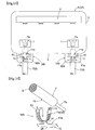
- This output cable 7 is fixed to the box body A1 separately from its electrical connection with the terminal plate 1, by means of an inventive output cable fixation arrangement using a cable fastener (clamper) 16A made of a plate metal.
- the cable fastener 16A is made of a metal material, stress relaxation is less likely to occur in this member as compared with a cable fastener made of a resin. So even under an adverse condition such as high temperature and high humidity where the solar cell module is to be installed, the possibility of positional displacement of the output cable 7 relative to the terminal box A can be reduced for an extended period of time.
- the output cable 7 includes the core wire 7a and an insulating coating layer 9 coating the core wire 7a.
- the cable fastener 16A includes a first fixing portion 11a to be fixed on the insulating coating layer 9 constituting the barrel portion of the output cable 7 and a second fixing portion 11b to be fixed to a portion of the box body A1.
- the first fixing portion 11a is constituted from a curved band plate member curved in the letter-U shape. This first fixing portion 11a can be wound and held on the insulating coating layer 9 as being wound around the insulating coating layer 9 and fixed thereto by caulking. Further, the first fixing portion 11a forms a plurality of linear projections 12 projecting toward the inner peripheral face along the longitudinal direction of the curved band like plate member (first fixing portion) 11a. With this, the first fixing portion 11a can apply a concentrated load to the outer peripheral face of the insulating coating layer 9 at the time of fixing by caulking. At the opposed longitudinal ends of the curved band plate member 11a, there are formed pawls 13 which bite into the output cable 7 to be adjacent each other in the plate width direction when being fixed to the output cable 7 by caulking.
- the second fixing portion 11b is configured to be wound and held around a portion of the box body A1. More particularly, the second fixing portion 11b includes a narrow connecting plate member 14 extended from the curved band plate member 11a and having a narrower width than the output cable 7 and a flat band plate member 15 formed continuously from the connecting plate member 14 and fixedly calked to a portion of the box body A1 and the second fixing portion 11b projects in the letter T-shaped from the curved band plate member 11a.
- a cable fixing portion 16B is formed of resin and in flush with the lower face of the bottom plate 3 of the box body A1. With this cable fixing portion 16B, the curved band plate member (first fixing portion) 11a of the cable fastener 16A fixes the output cable 7 fixedly caulked therein in advance, to the box body A1.
- the cable fixing portion 16B includes a cable holding portion 37.
- This cable holding portion 37 allows insertion thereto of the second fixing portion 11b of the output cable 7 to which the cable fastener 16A is attached in advance.
- this holding portion 37 holds a fixing portion 33 to which the curved band plate member 11a is fixed and a cable portion 34 adjacent the curved band plate member 11a.
- the cable fixing portion 16B includes a caulking fixing portion (see Fig. 22 ) 20 to which the flat band plate member 15 of the second fixing portion 11b is to be fixedly caulked.
- the cable holding portion 37 forms a cylindrical portion 22 and this cylindrical portion 22 forms a slit 21.
- This slit 21 has a width designed to allow passage of the second fixing portion 11b (connecting plate member 14) when the output cable 7 to which the curved band plate member 11a of the cable fastener 16A is fixedly caulked in advance is to be inserted into the cable insertion portion 6 and which is designed also to be capable of preventing inadvertent withdrawal of the output cable 7 along the radial direction.
- the inner side of this cylindrical portion 22 is configured to be capable of surrounding an area of at least half the perimeter or more of the fixing portion 3 of the output cable 7 to which the curved band plate member 11a is fixedly caulked and a cable portion (the portion of the output cable 7 adjacent the curved band plate member 11a) 34 on the forward side of this fixed portion 33 along the cable insertion direction.
- a caulking fixing portion 38 includes a rectangular hole 23 which allows insertion of the flat band plate member 15 from the lower face side of the bottom plate 3 with the output cable 7 to which the curved band plate member 11a is fixedly caulked being held to the holding portion 37. Further, the caulking fixing portion 38 is provided with fixed portions 26 to which the flat band plate member 15 is to be fixedly caulked with opposed ends thereof being bent thereon.
- the fixed portions 26 are provided on the opposed sides across a slit 21, as corner portions 26, including, at a portion of the cylindrical portion 22 facing the rectangular hole 23, upper face portions 24 extending parallel with the lower face of the bottom portion 3 and side face portions 25 extending along the direction perpendicular to the upper face portions 24 and along the direction perpendicular to the side wall 5. Then, as the connecting plate member 14 is plastically deformed to insert the flat band plate member 15 into the rectangular hole 23 and the opposed ends of this flat band plate member 15 are bent along side face portions 25 of the respective corner portions (fixed portions) 26, the flat band plate member 15 is fixed by caulking.
- the flat band plate member 15 include a pawl 28 which enters the recess 27 defined in the lower face of the bottom 3 in association with caulking fixation of the flat band plate member 15 to the caulking fixing portion 38. Therefore, when it is desired to release the calking fixation of the flat band plate member 15 to the caulking fixing portion 38, this can be released easily by raising this pawl 28 from the recess27 by means of e.g. a driver.
- Figs. 23 through 26 show a further embodiment of the output cable fixation arrangement according to the present invention.
- the box body A1 includes, on the outer side of the box, bosses 6a to communicate to the cable insertion portions 6 formed in the side wall 5.
- the bottom plate 3 forms a pair of rectangular through holes 29 for introducing bent opposed ends of the flat band plate members 15 of the second fixing portions 11b.
- the bottom plate 3 further includes caulking fixing portions 38 for fixedly caulking the flat band plate members 15 to the bottom plate 3.
- the output cable 7 before caulking fixation of the curved band plate member (first fixing portion) 11a of the cable fastener 16A thereto is inserted to the inside of the box body A1 through the boss 6a and the cable insertion portion 6 from the outside of the box body A1. Then, after the curved band plate member 11a of the cable fastener 16A to the output cable 7, the flat band plate member 15 is fixedly caulked to the bottom plate 3.
- the output cable 7 to which the curved band plate member (first fixing portion) 11a of the cable fastener 16A is fixedly caulked in advance is drawn from the inside of the box body A1 through the cable insertion portion 6 and the boss 6a to the outside of the box body A1. Thereafter, the calking fixation to the bottom plate 3 may be effected alternatively by bending the opposed ends of the flat band plate member 15 of the cable fastener 16A toward the inside the rectangular through hole 29.
- the rest of the construction of this embodiment is same as that of the first embodiment.
- the terminal box of the present invention may be employed as a terminal box including a box body attachable to an attachment target, a plurality of terminal plates juxtaposed under a mutually isolated state inside the box body, and a diode conductively connected to and between adjacent terminal plates.
- the output cable connection arrangement of the present invention may be used as an output cable connection arrangement for a solar cell module terminal box for electrically connecting an output cable to a terminal plate provided inside the terminal box to be electrically connected to a solar cell module through a cable insertion portion provided in the terminal box from the outside of the terminal box.
- the output cable fixation arrangement of the present invention may be used as an output cable fixation arrangement for a solar cell module terminal box wherein a terminal plate to be electrically connected to a solar cell module is provided inside a terminal box and an output cable electrically connected to the terminal plate is extended to the outside of the terminal box.
Landscapes
- Photovoltaic Devices (AREA)
- Coupling Device And Connection With Printed Circuit (AREA)
Priority Applications (1)
| Application Number | Priority Date | Filing Date | Title |
|---|---|---|---|
| EP18161662.4A EP3355468B1 (fr) | 2010-09-29 | 2011-09-22 | Dispositif de fixation pour le câble de sortie |
Applications Claiming Priority (3)
| Application Number | Priority Date | Filing Date | Title |
|---|---|---|---|
| JP2010219972A JP5516982B2 (ja) | 2010-09-29 | 2010-09-29 | 端子ボックス |
| JP2010219973A JP2012074631A (ja) | 2010-09-29 | 2010-09-29 | 太陽電池モジュール用端子ボックスの出力ケーブルの接続構造 |
| JP2010219971A JP5541597B2 (ja) | 2010-09-29 | 2010-09-29 | 太陽電池モジュール用端子ボックスの出力ケーブル固定構造 |
Related Child Applications (2)
| Application Number | Title | Priority Date | Filing Date |
|---|---|---|---|
| EP18161662.4A Division EP3355468B1 (fr) | 2010-09-29 | 2011-09-22 | Dispositif de fixation pour le câble de sortie |
| EP18161662.4A Division-Into EP3355468B1 (fr) | 2010-09-29 | 2011-09-22 | Dispositif de fixation pour le câble de sortie |
Publications (2)
| Publication Number | Publication Date |
|---|---|
| EP2437312A1 true EP2437312A1 (fr) | 2012-04-04 |
| EP2437312B1 EP2437312B1 (fr) | 2019-05-15 |
Family
ID=44674097
Family Applications (2)
| Application Number | Title | Priority Date | Filing Date |
|---|---|---|---|
| EP11007708.8A Not-in-force EP2437312B1 (fr) | 2010-09-29 | 2011-09-22 | Boîte à bornes |
| EP18161662.4A Not-in-force EP3355468B1 (fr) | 2010-09-29 | 2011-09-22 | Dispositif de fixation pour le câble de sortie |
Family Applications After (1)
| Application Number | Title | Priority Date | Filing Date |
|---|---|---|---|
| EP18161662.4A Not-in-force EP3355468B1 (fr) | 2010-09-29 | 2011-09-22 | Dispositif de fixation pour le câble de sortie |
Country Status (4)
| Country | Link |
|---|---|
| US (1) | US8854825B2 (fr) |
| EP (2) | EP2437312B1 (fr) |
| CN (1) | CN102437202B (fr) |
| CA (1) | CA2752914C (fr) |
Families Citing this family (16)
| Publication number | Priority date | Publication date | Assignee | Title |
|---|---|---|---|---|
| DE102008062034B4 (de) * | 2008-12-12 | 2010-08-12 | Tyco Electronics Amp Gmbh | Verbindungsvorrichtung zum Anschluss an ein Solarmodul und Solarmodul mit einer solchen Verbindungsvorrichtung |
| DE102010002565B8 (de) * | 2010-03-04 | 2012-03-22 | Tyco Electronics Amp Gmbh | Anschlussvorrichtung für ein Solarmodul |
| JP5729648B2 (ja) * | 2011-10-13 | 2015-06-03 | ホシデン株式会社 | 太陽電池モジュール用端子ボックス |
| DE102011119173B4 (de) * | 2011-11-23 | 2013-11-28 | Phoenix Contact Gmbh & Co. Kg | Generatoranschlusskasten fürPhotovoltaikanlagen und Eingangsmodule |
| US20130255999A1 (en) * | 2012-03-27 | 2013-10-03 | First Solar, Inc. | Method and apparatus for providing a conductor interface for a photovoltaic module |
| JP6472318B2 (ja) * | 2015-04-30 | 2019-02-20 | ホシデン株式会社 | 端子ボックス及び太陽電池モジュール |
| CN205051644U (zh) * | 2015-08-26 | 2016-02-24 | 泰科电子(上海)有限公司 | 光伏接线盒 |
| CN106685339A (zh) * | 2015-11-06 | 2017-05-17 | 泰科电子(上海)有限公司 | 光伏接线盒和二极管 |
| CN107666278A (zh) * | 2016-07-27 | 2018-02-06 | 江苏绿扬光伏科技有限公司 | 一种新型太阳能组件用接线盒 |
| CN107960031A (zh) * | 2017-12-15 | 2018-04-24 | 田永胜 | 一种交通系统的防水设备 |
| CN108039767A (zh) * | 2017-12-30 | 2018-05-15 | 孙振华 | 一种基于新型逆变器的光伏供电系统 |
| CN108183681A (zh) * | 2017-12-30 | 2018-06-19 | 孙振华 | 一种光伏逆变器 |
| CN108540086A (zh) * | 2018-01-18 | 2018-09-14 | 浙江人和光伏科技有限公司 | 一种太阳能电池接线盒的导电模块 |
| JP7761483B2 (ja) | 2021-12-28 | 2025-10-28 | 株式会社トーキン | ノイズフィルタ |
| CN117878792A (zh) * | 2023-02-10 | 2024-04-12 | 刘立秀 | 一种太阳能光伏的接线盒 |
| CN116456633B (zh) * | 2023-03-06 | 2026-04-03 | 南阳市一通防爆电气有限公司 | 一体化隔爆控制终端 |
Citations (3)
| Publication number | Priority date | Publication date | Assignee | Title |
|---|---|---|---|---|
| DE20311183U1 (de) * | 2003-07-21 | 2004-07-08 | Tyco Electronics Amp Gmbh | Anschlussdose für ein Solarpaneel und Solarpaneel |
| EP1587149A2 (fr) * | 2004-04-13 | 2005-10-19 | Sumitomo Wiring Systems, Ltd. | Boítier de raccordement pour un module de cellules solaires et son procédé de montage |
| WO2009135691A1 (fr) * | 2008-05-09 | 2009-11-12 | Yamaichi Electronics Deutschland Gmbh | Boîte de jonction, utilisations d'une boîte de jonction et procédé |
Family Cites Families (15)
| Publication number | Priority date | Publication date | Assignee | Title |
|---|---|---|---|---|
| JP5192103B2 (ja) | 2000-02-29 | 2013-05-08 | 木谷電器株式会社 | 太陽電池モジュール用端子ボックス |
| JP3721054B2 (ja) | 2000-06-20 | 2005-11-30 | 株式会社オートネットワーク技術研究所 | シールドコネクタ |
| JP2002076412A (ja) | 2000-08-28 | 2002-03-15 | Yukita Electric Wire Co Ltd | 太陽電池モジュール |
| JP2004152548A (ja) | 2002-10-29 | 2004-05-27 | Hitachi Cable Ltd | シールド層付ケーブルの端末構造 |
| JP4357972B2 (ja) | 2004-01-26 | 2009-11-04 | 株式会社三社電機製作所 | 入出力端子付き太陽電池バイパスダイオードモジュールとその製造方法 |
| JP4452997B2 (ja) | 2004-04-30 | 2010-04-21 | 住友電装株式会社 | 太陽電池モジュール用端子ボックス |
| US8107207B2 (en) * | 2008-08-08 | 2012-01-31 | Surge Suppression Incorporated | Potted electrical circuit with protective insulation |
| JP3852711B1 (ja) * | 2005-11-09 | 2006-12-06 | 住友電装株式会社 | 太陽電池モジュール用端子ボックス |
| DE102007020843A1 (de) * | 2007-03-28 | 2008-10-02 | Günther Spelsberg GmbH & Co. KG | Paneldose |
| US20080278898A1 (en) * | 2007-05-09 | 2008-11-13 | Silver-Stone Technology Co., Ltd. | Connecting modular structure for DC output of power supply |
| JP5070111B2 (ja) | 2008-04-03 | 2012-11-07 | 本多通信工業株式会社 | 太陽電池モジュール用端子ボックス |
| JP5095584B2 (ja) | 2008-11-11 | 2012-12-12 | 行田電線株式会社 | 太陽電池モジュール用端子ボックス |
| US8563876B1 (en) * | 2010-03-03 | 2013-10-22 | Arlington Industries, Inc. | Cable holding outlet box |
| US8432699B2 (en) * | 2010-09-17 | 2013-04-30 | Delta Electronics, Inc. | Junction box and electrical connection mechanism thereof |
| JP5570361B2 (ja) * | 2010-09-22 | 2014-08-13 | 三菱電機株式会社 | 防水型電子装置及びその組立方法 |
-
2011
- 2011-09-20 CA CA2752914A patent/CA2752914C/fr not_active Expired - Fee Related
- 2011-09-22 US US13/239,690 patent/US8854825B2/en active Active
- 2011-09-22 EP EP11007708.8A patent/EP2437312B1/fr not_active Not-in-force
- 2011-09-22 EP EP18161662.4A patent/EP3355468B1/fr not_active Not-in-force
- 2011-09-28 CN CN201110295215.7A patent/CN102437202B/zh not_active Expired - Fee Related
Patent Citations (3)
| Publication number | Priority date | Publication date | Assignee | Title |
|---|---|---|---|---|
| DE20311183U1 (de) * | 2003-07-21 | 2004-07-08 | Tyco Electronics Amp Gmbh | Anschlussdose für ein Solarpaneel und Solarpaneel |
| EP1587149A2 (fr) * | 2004-04-13 | 2005-10-19 | Sumitomo Wiring Systems, Ltd. | Boítier de raccordement pour un module de cellules solaires et son procédé de montage |
| WO2009135691A1 (fr) * | 2008-05-09 | 2009-11-12 | Yamaichi Electronics Deutschland Gmbh | Boîte de jonction, utilisations d'une boîte de jonction et procédé |
Also Published As
| Publication number | Publication date |
|---|---|
| EP3355468B1 (fr) | 2021-03-10 |
| CN102437202A (zh) | 2012-05-02 |
| US8854825B2 (en) | 2014-10-07 |
| EP3355468A1 (fr) | 2018-08-01 |
| CA2752914C (fr) | 2019-06-04 |
| EP2437312B1 (fr) | 2019-05-15 |
| CN102437202B (zh) | 2016-02-24 |
| US20120075825A1 (en) | 2012-03-29 |
| CA2752914A1 (fr) | 2012-03-29 |
Similar Documents
| Publication | Publication Date | Title |
|---|---|---|
| EP3355468B1 (fr) | Dispositif de fixation pour le câble de sortie | |
| JP7550273B2 (ja) | センサユニットおよび蓄電モジュール | |
| EP1120837B1 (fr) | Panneau de cellules solaires | |
| US6655987B2 (en) | Terminal box apparatus for solar cell module | |
| US7432439B2 (en) | Terminal box | |
| KR101297186B1 (ko) | 이차전지 팩 | |
| JP5254246B2 (ja) | 生産性及び構造的安定性が優れたバッテリーパック | |
| JP2019519915A (ja) | 外部電気コネクタを有する光起電力モジュール | |
| WO2011111676A1 (fr) | Module batterie | |
| US20050054240A1 (en) | Accumulating element module | |
| EP3063835B1 (fr) | Agencement de connexion pour connecter au moins une source de tension et/ou un collecteur de tension, se présentant sous la forme d'une cellule d'une batterie de traction, à un composant électrique externe, et agencement électrique comprenant un agencement de connexion | |
| KR20230161674A (ko) | 부식을 방지할 수 있는 커버 부재가 구비된 플렉시블 버스바 및 이를 포함하는 전지 모듈 | |
| EP3641017B1 (fr) | Batterie secondaire | |
| WO2010052207A2 (fr) | Dispositif de raccordement pour un module solaire photovoltaïque | |
| JP4452997B2 (ja) | 太陽電池モジュール用端子ボックス | |
| AU2006228598B2 (en) | Connector housing assembly and method for housing a connector contact connecting a wire to a conducting lead in a piece of foil | |
| FI80810C (fi) | Anordning vid ackumulatorbatterier foer att foerhindra felkoppling i ett pao batterilocket befintligt faestoera. | |
| JP5046568B2 (ja) | 電池パック | |
| JP7737080B2 (ja) | コネクタ | |
| JP2026020620A (ja) | バスバモジュール | |
| JP2003096982A (ja) | 瓦一体型太陽電池モジュール | |
| WO2011029871A2 (fr) | Boîtier de connecteur | |
| HK1118960A (en) | Connector housing assembly and method for housing a connector contact connecting a wire to a conducting lead in a piece of foil |
Legal Events
| Date | Code | Title | Description |
|---|---|---|---|
| PUAI | Public reference made under article 153(3) epc to a published international application that has entered the european phase |
Free format text: ORIGINAL CODE: 0009012 |
|
| AK | Designated contracting states |
Kind code of ref document: A1 Designated state(s): AL AT BE BG CH CY CZ DE DK EE ES FI FR GB GR HR HU IE IS IT LI LT LU LV MC MK MT NL NO PL PT RO RS SE SI SK SM TR |
|
| AX | Request for extension of the european patent |
Extension state: BA ME |
|
| 17P | Request for examination filed |
Effective date: 20120919 |
|
| STAA | Information on the status of an ep patent application or granted ep patent |
Free format text: STATUS: EXAMINATION IS IN PROGRESS |
|
| 17Q | First examination report despatched |
Effective date: 20171031 |
|
| REG | Reference to a national code |
Ref country code: DE Ref legal event code: R079 Ref document number: 602011058932 Country of ref document: DE Free format text: PREVIOUS MAIN CLASS: H01L0031048000 Ipc: H02S0040340000 |
|
| GRAP | Despatch of communication of intention to grant a patent |
Free format text: ORIGINAL CODE: EPIDOSNIGR1 |
|
| STAA | Information on the status of an ep patent application or granted ep patent |
Free format text: STATUS: GRANT OF PATENT IS INTENDED |
|
| RIC1 | Information provided on ipc code assigned before grant |
Ipc: H02S 40/34 20140101AFI20181207BHEP |
|
| INTG | Intention to grant announced |
Effective date: 20190109 |
|
| RIC1 | Information provided on ipc code assigned before grant |
Ipc: H02S 40/34 20140101AFI20181207BHEP |
|
| GRAS | Grant fee paid |
Free format text: ORIGINAL CODE: EPIDOSNIGR3 |
|
| GRAA | (expected) grant |
Free format text: ORIGINAL CODE: 0009210 |
|
| STAA | Information on the status of an ep patent application or granted ep patent |
Free format text: STATUS: THE PATENT HAS BEEN GRANTED |
|
| AK | Designated contracting states |
Kind code of ref document: B1 Designated state(s): AL AT BE BG CH CY CZ DE DK EE ES FI FR GB GR HR HU IE IS IT LI LT LU LV MC MK MT NL NO PL PT RO RS SE SI SK SM TR |
|
| REG | Reference to a national code |
Ref country code: CH Ref legal event code: EP Ref country code: GB Ref legal event code: FG4D |
|
| REG | Reference to a national code |
Ref country code: DE Ref legal event code: R096 Ref document number: 602011058932 Country of ref document: DE |
|
| REG | Reference to a national code |
Ref country code: IE Ref legal event code: FG4D |
|
| REG | Reference to a national code |
Ref country code: NL Ref legal event code: MP Effective date: 20190515 |
|
| REG | Reference to a national code |
Ref country code: LT Ref legal event code: MG4D |
|
| PG25 | Lapsed in a contracting state [announced via postgrant information from national office to epo] |
Ref country code: HR Free format text: LAPSE BECAUSE OF FAILURE TO SUBMIT A TRANSLATION OF THE DESCRIPTION OR TO PAY THE FEE WITHIN THE PRESCRIBED TIME-LIMIT Effective date: 20190515 Ref country code: LT Free format text: LAPSE BECAUSE OF FAILURE TO SUBMIT A TRANSLATION OF THE DESCRIPTION OR TO PAY THE FEE WITHIN THE PRESCRIBED TIME-LIMIT Effective date: 20190515 Ref country code: SE Free format text: LAPSE BECAUSE OF FAILURE TO SUBMIT A TRANSLATION OF THE DESCRIPTION OR TO PAY THE FEE WITHIN THE PRESCRIBED TIME-LIMIT Effective date: 20190515 Ref country code: NL Free format text: LAPSE BECAUSE OF FAILURE TO SUBMIT A TRANSLATION OF THE DESCRIPTION OR TO PAY THE FEE WITHIN THE PRESCRIBED TIME-LIMIT Effective date: 20190515 Ref country code: FI Free format text: LAPSE BECAUSE OF FAILURE TO SUBMIT A TRANSLATION OF THE DESCRIPTION OR TO PAY THE FEE WITHIN THE PRESCRIBED TIME-LIMIT Effective date: 20190515 Ref country code: AL Free format text: LAPSE BECAUSE OF FAILURE TO SUBMIT A TRANSLATION OF THE DESCRIPTION OR TO PAY THE FEE WITHIN THE PRESCRIBED TIME-LIMIT Effective date: 20190515 Ref country code: ES Free format text: LAPSE BECAUSE OF FAILURE TO SUBMIT A TRANSLATION OF THE DESCRIPTION OR TO PAY THE FEE WITHIN THE PRESCRIBED TIME-LIMIT Effective date: 20190515 Ref country code: NO Free format text: LAPSE BECAUSE OF FAILURE TO SUBMIT A TRANSLATION OF THE DESCRIPTION OR TO PAY THE FEE WITHIN THE PRESCRIBED TIME-LIMIT Effective date: 20190815 Ref country code: PT Free format text: LAPSE BECAUSE OF FAILURE TO SUBMIT A TRANSLATION OF THE DESCRIPTION OR TO PAY THE FEE WITHIN THE PRESCRIBED TIME-LIMIT Effective date: 20190915 |
|
| PG25 | Lapsed in a contracting state [announced via postgrant information from national office to epo] |
Ref country code: BG Free format text: LAPSE BECAUSE OF FAILURE TO SUBMIT A TRANSLATION OF THE DESCRIPTION OR TO PAY THE FEE WITHIN THE PRESCRIBED TIME-LIMIT Effective date: 20190815 Ref country code: GR Free format text: LAPSE BECAUSE OF FAILURE TO SUBMIT A TRANSLATION OF THE DESCRIPTION OR TO PAY THE FEE WITHIN THE PRESCRIBED TIME-LIMIT Effective date: 20190816 Ref country code: LV Free format text: LAPSE BECAUSE OF FAILURE TO SUBMIT A TRANSLATION OF THE DESCRIPTION OR TO PAY THE FEE WITHIN THE PRESCRIBED TIME-LIMIT Effective date: 20190515 Ref country code: RS Free format text: LAPSE BECAUSE OF FAILURE TO SUBMIT A TRANSLATION OF THE DESCRIPTION OR TO PAY THE FEE WITHIN THE PRESCRIBED TIME-LIMIT Effective date: 20190515 |
|
| REG | Reference to a national code |
Ref country code: AT Ref legal event code: MK05 Ref document number: 1134612 Country of ref document: AT Kind code of ref document: T Effective date: 20190515 |
|
| PG25 | Lapsed in a contracting state [announced via postgrant information from national office to epo] |
Ref country code: EE Free format text: LAPSE BECAUSE OF FAILURE TO SUBMIT A TRANSLATION OF THE DESCRIPTION OR TO PAY THE FEE WITHIN THE PRESCRIBED TIME-LIMIT Effective date: 20190515 Ref country code: DK Free format text: LAPSE BECAUSE OF FAILURE TO SUBMIT A TRANSLATION OF THE DESCRIPTION OR TO PAY THE FEE WITHIN THE PRESCRIBED TIME-LIMIT Effective date: 20190515 Ref country code: AT Free format text: LAPSE BECAUSE OF FAILURE TO SUBMIT A TRANSLATION OF THE DESCRIPTION OR TO PAY THE FEE WITHIN THE PRESCRIBED TIME-LIMIT Effective date: 20190515 Ref country code: CZ Free format text: LAPSE BECAUSE OF FAILURE TO SUBMIT A TRANSLATION OF THE DESCRIPTION OR TO PAY THE FEE WITHIN THE PRESCRIBED TIME-LIMIT Effective date: 20190515 Ref country code: RO Free format text: LAPSE BECAUSE OF FAILURE TO SUBMIT A TRANSLATION OF THE DESCRIPTION OR TO PAY THE FEE WITHIN THE PRESCRIBED TIME-LIMIT Effective date: 20190515 Ref country code: SK Free format text: LAPSE BECAUSE OF FAILURE TO SUBMIT A TRANSLATION OF THE DESCRIPTION OR TO PAY THE FEE WITHIN THE PRESCRIBED TIME-LIMIT Effective date: 20190515 |
|
| REG | Reference to a national code |
Ref country code: DE Ref legal event code: R097 Ref document number: 602011058932 Country of ref document: DE |
|
| PG25 | Lapsed in a contracting state [announced via postgrant information from national office to epo] |
Ref country code: IT Free format text: LAPSE BECAUSE OF FAILURE TO SUBMIT A TRANSLATION OF THE DESCRIPTION OR TO PAY THE FEE WITHIN THE PRESCRIBED TIME-LIMIT Effective date: 20190515 Ref country code: SM Free format text: LAPSE BECAUSE OF FAILURE TO SUBMIT A TRANSLATION OF THE DESCRIPTION OR TO PAY THE FEE WITHIN THE PRESCRIBED TIME-LIMIT Effective date: 20190515 |
|
| PLBE | No opposition filed within time limit |
Free format text: ORIGINAL CODE: 0009261 |
|
| STAA | Information on the status of an ep patent application or granted ep patent |
Free format text: STATUS: NO OPPOSITION FILED WITHIN TIME LIMIT |
|
| PG25 | Lapsed in a contracting state [announced via postgrant information from national office to epo] |
Ref country code: TR Free format text: LAPSE BECAUSE OF FAILURE TO SUBMIT A TRANSLATION OF THE DESCRIPTION OR TO PAY THE FEE WITHIN THE PRESCRIBED TIME-LIMIT Effective date: 20190515 |
|
| 26N | No opposition filed |
Effective date: 20200218 |
|
| PG25 | Lapsed in a contracting state [announced via postgrant information from national office to epo] |
Ref country code: PL Free format text: LAPSE BECAUSE OF FAILURE TO SUBMIT A TRANSLATION OF THE DESCRIPTION OR TO PAY THE FEE WITHIN THE PRESCRIBED TIME-LIMIT Effective date: 20190515 |
|
| PG25 | Lapsed in a contracting state [announced via postgrant information from national office to epo] |
Ref country code: MC Free format text: LAPSE BECAUSE OF FAILURE TO SUBMIT A TRANSLATION OF THE DESCRIPTION OR TO PAY THE FEE WITHIN THE PRESCRIBED TIME-LIMIT Effective date: 20190515 Ref country code: SI Free format text: LAPSE BECAUSE OF FAILURE TO SUBMIT A TRANSLATION OF THE DESCRIPTION OR TO PAY THE FEE WITHIN THE PRESCRIBED TIME-LIMIT Effective date: 20190515 |
|
| REG | Reference to a national code |
Ref country code: CH Ref legal event code: PL |
|
| PG25 | Lapsed in a contracting state [announced via postgrant information from national office to epo] |
Ref country code: LU Free format text: LAPSE BECAUSE OF NON-PAYMENT OF DUE FEES Effective date: 20190922 Ref country code: CH Free format text: LAPSE BECAUSE OF NON-PAYMENT OF DUE FEES Effective date: 20190930 Ref country code: IE Free format text: LAPSE BECAUSE OF NON-PAYMENT OF DUE FEES Effective date: 20190922 Ref country code: LI Free format text: LAPSE BECAUSE OF NON-PAYMENT OF DUE FEES Effective date: 20190930 |
|
| REG | Reference to a national code |
Ref country code: BE Ref legal event code: MM Effective date: 20190930 |
|
| PG25 | Lapsed in a contracting state [announced via postgrant information from national office to epo] |
Ref country code: BE Free format text: LAPSE BECAUSE OF NON-PAYMENT OF DUE FEES Effective date: 20190930 |
|
| GBPC | Gb: european patent ceased through non-payment of renewal fee |
Effective date: 20190922 |
|
| PG25 | Lapsed in a contracting state [announced via postgrant information from national office to epo] |
Ref country code: GB Free format text: LAPSE BECAUSE OF NON-PAYMENT OF DUE FEES Effective date: 20190922 |
|
| PG25 | Lapsed in a contracting state [announced via postgrant information from national office to epo] |
Ref country code: CY Free format text: LAPSE BECAUSE OF FAILURE TO SUBMIT A TRANSLATION OF THE DESCRIPTION OR TO PAY THE FEE WITHIN THE PRESCRIBED TIME-LIMIT Effective date: 20190515 |
|
| PG25 | Lapsed in a contracting state [announced via postgrant information from national office to epo] |
Ref country code: IS Free format text: LAPSE BECAUSE OF FAILURE TO SUBMIT A TRANSLATION OF THE DESCRIPTION OR TO PAY THE FEE WITHIN THE PRESCRIBED TIME-LIMIT Effective date: 20190915 |
|
| PG25 | Lapsed in a contracting state [announced via postgrant information from national office to epo] |
Ref country code: MT Free format text: LAPSE BECAUSE OF FAILURE TO SUBMIT A TRANSLATION OF THE DESCRIPTION OR TO PAY THE FEE WITHIN THE PRESCRIBED TIME-LIMIT Effective date: 20190515 Ref country code: HU Free format text: LAPSE BECAUSE OF FAILURE TO SUBMIT A TRANSLATION OF THE DESCRIPTION OR TO PAY THE FEE WITHIN THE PRESCRIBED TIME-LIMIT; INVALID AB INITIO Effective date: 20110922 |
|
| PGFP | Annual fee paid to national office [announced via postgrant information from national office to epo] |
Ref country code: FR Payment date: 20210927 Year of fee payment: 11 |
|
| PGFP | Annual fee paid to national office [announced via postgrant information from national office to epo] |
Ref country code: DE Payment date: 20210827 Year of fee payment: 11 |
|
| PG25 | Lapsed in a contracting state [announced via postgrant information from national office to epo] |
Ref country code: MK Free format text: LAPSE BECAUSE OF FAILURE TO SUBMIT A TRANSLATION OF THE DESCRIPTION OR TO PAY THE FEE WITHIN THE PRESCRIBED TIME-LIMIT Effective date: 20190515 |
|
| REG | Reference to a national code |
Ref country code: DE Ref legal event code: R119 Ref document number: 602011058932 Country of ref document: DE |
|
| PG25 | Lapsed in a contracting state [announced via postgrant information from national office to epo] |
Ref country code: FR Free format text: LAPSE BECAUSE OF NON-PAYMENT OF DUE FEES Effective date: 20220930 Ref country code: DE Free format text: LAPSE BECAUSE OF NON-PAYMENT OF DUE FEES Effective date: 20230401 |