EP2437352A1 - Liaison par brasage - Google Patents
Liaison par brasage Download PDFInfo
- Publication number
- EP2437352A1 EP2437352A1 EP11450127A EP11450127A EP2437352A1 EP 2437352 A1 EP2437352 A1 EP 2437352A1 EP 11450127 A EP11450127 A EP 11450127A EP 11450127 A EP11450127 A EP 11450127A EP 2437352 A1 EP2437352 A1 EP 2437352A1
- Authority
- EP
- European Patent Office
- Prior art keywords
- pin
- recess
- solder joint
- solder
- joint according
- Prior art date
- Legal status (The legal status is an assumption and is not a legal conclusion. Google has not performed a legal analysis and makes no representation as to the accuracy of the status listed.)
- Granted
Links
- 229910000679 solder Inorganic materials 0.000 title claims abstract description 77
- 239000000463 material Substances 0.000 claims abstract description 20
- 238000004519 manufacturing process Methods 0.000 description 12
- 239000007789 gas Substances 0.000 description 10
- 238000012545 processing Methods 0.000 description 8
- 230000006378 damage Effects 0.000 description 3
- 230000000694 effects Effects 0.000 description 3
- 239000011521 glass Substances 0.000 description 3
- 238000010008 shearing Methods 0.000 description 3
- 238000009736 wetting Methods 0.000 description 3
- 230000000712 assembly Effects 0.000 description 2
- 238000000429 assembly Methods 0.000 description 2
- 230000005540 biological transmission Effects 0.000 description 2
- 150000001875 compounds Chemical class 0.000 description 2
- 239000002184 metal Substances 0.000 description 2
- 238000012805 post-processing Methods 0.000 description 2
- 238000005476 soldering Methods 0.000 description 2
- 229910000831 Steel Inorganic materials 0.000 description 1
- 230000001133 acceleration Effects 0.000 description 1
- 229910045601 alloy Inorganic materials 0.000 description 1
- 239000000956 alloy Substances 0.000 description 1
- 230000015572 biosynthetic process Effects 0.000 description 1
- 239000000567 combustion gas Substances 0.000 description 1
- 238000000227 grinding Methods 0.000 description 1
- 239000012535 impurity Substances 0.000 description 1
- 238000003780 insertion Methods 0.000 description 1
- 230000037431 insertion Effects 0.000 description 1
- 230000003993 interaction Effects 0.000 description 1
- 238000003754 machining Methods 0.000 description 1
- 230000005499 meniscus Effects 0.000 description 1
- 238000000034 method Methods 0.000 description 1
- 230000035515 penetration Effects 0.000 description 1
- 238000002360 preparation method Methods 0.000 description 1
- 239000011265 semifinished product Substances 0.000 description 1
- 239000010959 steel Substances 0.000 description 1
Images


Classifications
-
- H—ELECTRICITY
- H01—ELECTRIC ELEMENTS
- H01R—ELECTRICALLY-CONDUCTIVE CONNECTIONS; STRUCTURAL ASSOCIATIONS OF A PLURALITY OF MUTUALLY-INSULATED ELECTRICAL CONNECTING ELEMENTS; COUPLING DEVICES; CURRENT COLLECTORS
- H01R4/00—Electrically-conductive connections between two or more conductive members in direct contact, i.e. touching one another; Means for effecting or maintaining such contact; Electrically-conductive connections having two or more spaced connecting locations for conductors and using contact members penetrating insulation
- H01R4/02—Soldered or welded connections
- H01R4/027—Soldered or welded connections comprising means for positioning or holding the parts to be soldered or welded
-
- F—MECHANICAL ENGINEERING; LIGHTING; HEATING; WEAPONS; BLASTING
- F42—AMMUNITION; BLASTING
- F42B—EXPLOSIVE CHARGES, e.g. FOR BLASTING, FIREWORKS, AMMUNITION
- F42B3/00—Blasting cartridges, i.e. case and explosive
- F42B3/10—Initiators therefor
- F42B3/103—Mounting initiator heads in initiators; Sealing-plugs
-
- H—ELECTRICITY
- H01—ELECTRIC ELEMENTS
- H01R—ELECTRICALLY-CONDUCTIVE CONNECTIONS; STRUCTURAL ASSOCIATIONS OF A PLURALITY OF MUTUALLY-INSULATED ELECTRICAL CONNECTING ELEMENTS; COUPLING DEVICES; CURRENT COLLECTORS
- H01R33/00—Coupling devices specially adapted for supporting apparatus and having one part acting as a holder providing support and electrical connection via a counterpart which is structurally associated with the apparatus, e.g. lamp holders; Separate parts thereof
- H01R33/05—Two-pole devices
- H01R33/06—Two-pole devices with two current-carrying pins, blades or analogous contacts, having their axes parallel to each other
-
- H—ELECTRICITY
- H01—ELECTRIC ELEMENTS
- H01R—ELECTRICALLY-CONDUCTIVE CONNECTIONS; STRUCTURAL ASSOCIATIONS OF A PLURALITY OF MUTUALLY-INSULATED ELECTRICAL CONNECTING ELEMENTS; COUPLING DEVICES; CURRENT COLLECTORS
- H01R24/00—Two-part coupling devices, or either of their cooperating parts, characterised by their overall structure
- H01R24/66—Two-part coupling devices, or either of their cooperating parts, characterised by their overall structure with pins, blades or analogous contacts and secured to apparatus or structure, e.g. to a wall
- H01R24/70—Two-part coupling devices, or either of their cooperating parts, characterised by their overall structure with pins, blades or analogous contacts and secured to apparatus or structure, e.g. to a wall with additional earth or shield contacts
Definitions
- the invention relates to a solder joint according to the preamble of claim 1.
- solder joints for attaching a thin pin to a surface substantially at right angles.
- the pin is provided with a substantially planar end face, which is butt soldered to the surface.
- the disadvantage of this is that the pens in question, due to the mass production, have no flat faces, and therefore a corresponding processing step is required before the solder joint can be made. Furthermore, such a solder joint tends to shear off the pins, and has the disadvantage of low vibration resistance.
- This is particularly disadvantageous when using correspondingly processed assemblies in vehicles disadvantage, since this can lead to increased failure rates.
- This has a particularly disadvantageous effect when used in safety-relevant devices, such as an igniter for an airbag, whose function must be ensured, in particular, at high accelerations occurring.
- solder joints in which the production of a flat surface according to the preceding paragraph is dispensed with.
- a first such known solder joint is provided to blunt the rounded ends of a contact pin to a surface.
- Such designs also have very poor mechanical properties.
- a second such known solder joint is provided to guide a pin through a through hole and attach a conventional solder joint on both sides in the throat between the pin and the body.
- solder joints are very inflexible in use.
- the object of the invention is therefore to provide a solder joint of the type mentioned above, with which the mentioned disadvantages can be avoided, with which the preparatory work for the preparation of a semifinished product can be reduced to the solder joint, and increases the safety of the solder joint, especially against shearing can be, and which is flexible.
- a solder joint can be formed, which has a high security against mechanical damage, especially against shearing, since due to the wetting of both the pin, and the lateral surface of the first recess any notch effects are avoided, and a lateral force transmission via the solder material on the lateral surface the first recess is made possible.
- a pin can essentially be processed without further preparatory mechanical processing since no planar end face is required. This allows pins with rounded or sharpened ends to be securely soldered without further processing of such ends.
- corresponding pins such as for the most preferred use in ignition base for gas generator igniter, after their production rounded ends. Such pins can now be processed without further post-processing. As a result, the production costs and the production costs can be reduced.
- a solder joint according to the invention is also versatile and flexible.
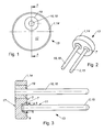
- the Fig. 1 to 12 each show preferred arrangements or details of arrangements of an electrically conductive body 1 and a - connected by means of a solder joint to the body 1 - electrically conductive first pin 2, wherein in a first surface 3 of the body 1, a first recess 4 is arranged the first pin 2 is arranged in regions in the first recess 4, wherein in a gap 5 between a first lateral surface 6 of the first recess 4 and the first pin 2, a solder material 7 is arranged, and wherein the solder material 7 at least partially both at the first pin 2, as well as on the first lateral surface 6 is arranged.
- a solder joint can be formed, which has a high security against mechanical damage, especially against shearing, since due to the wetting of both the first pin 2, and the first lateral surface 6 of the first recess 4 any notch effects are avoided, and a lateral power transmission via the solder material 7 is made possible on the first lateral surface 6 of the first recess 4.
- a first pin 2 can be processed essentially without further preparatory mechanical processing, since no plane end face is required. This allows pins with rounded or sharpened ends to be securely soldered without further processing of such ends.
- corresponding pins for example for the particularly preferred use in detonator socket 13 for gas generator igniter, after the production of rounded ends on. Such pins can now be processed without further post-processing. As a result, the production costs and the production costs can be reduced.
- a solder joint according to the invention is also versatile and flexible.
- solder joint designates a connection of two or more metallic parts by means of a molten solder, which at least partially wets the surfaces of the at least two interconnected parts, in particular at least partially diffused into the respective surfaces.
- solder material preferably comprises any type of alloy and / or a pure metal which can be used for hard and / or soft soldering, in particular any type of solder or solder.
- solder joints according to the invention relates to fuse base 13, as used for example in gas generators, airbags or belt tensioners for safety belts in vehicles use.
- a gas generator is a fire set, which is provided and designed so that its combustion gases fill a cavity, such as the interior of an airbag.
- the Fig. 1 to 12 show four different preferred embodiments of such Zündersockel 13. Subsequently, the solder joint according to the invention will be explained in more detail with reference to these preferred embodiments. However, the use of solder joints according to the invention is not limited to this application. This can also be provided for connecting other components or assemblies.
- the subject invention relates to a solder joint in which it is provided to connect a first pin 2, therefore a thin rod with a preferably round cross section, to a body 1.
- the body 1 has - to form the solder joint - a first surface 3, in which a first recess 4 is arranged.
- the first recess 4 which may be of different design, has a bottom region 8 and a first lateral surface 6.
- the bottom region 8 denotes a bottom of the first depression 4 and preferably the region surrounding this base normal to the first surface 3, in particular if the floor is not flat.
- the first lateral surface 6 denotes the surface which extends between the first surface 3 and the bottom region 8. It is preferably provided that the first lateral surface 6 is at least partially inclined and / or rounded relative to the first surface 3. It is preferably provided that the first recess 4 is frusto-conical or truncated pyramid shaped.
- the first pin 2 is arranged at least partially in the first recess 4. It is preferably provided that a diameter or a diagonal of the first recess 4 is always larger than a diameter or a corresponding diagonal of the first pin 2 in the region of the first recess 4. Thereby, there is a gap 5 between the first lateral surface 6 of the first Well 4 and arranged in this first pin 2. In this space 5 at least partially a solder material 7 is arranged, wherein it is preferably provided that substantially the entire bottom portion 8 of the first recess 4 is covered with the solder material 7. According to the invention it is further provided that the solder material 7 is at least partially disposed both on the first pin 2, and on the lateral surface 6, therefore liable.
- the Fig. 1 to 3 show a first preferred embodiment of a Zündersockels 13, with an electrically conductive base body 14, a first contact pin 15 and a second contact pin 16, wherein the first contact pin 15 is electrically conductively connected to the base body 14, and wherein the second contact pin 16, from the main body 14th electrically insulated and gas-tight, is guided by the main body 14.
- the first contact pin 15 is connected to the main body 14 by means of a solder connection according to the invention.
- the first contact pin 15 corresponds to the first pin 2, and the main body 14 to the body. 1
- the first contact pin 15, which is conductively connected to the main body 14, is preferably provided for the mass connection of the ignition base 13, whereas the second contact pin 16, which is electrically insulated from the main body 14, is intended for Power supply is provided.
- the main body 14 has a substantially cylindrical disc-shaped basic shape, and is preferably formed comprising steel.
- the second contact pin 16 is guided through a passage opening of the main body 14, and electrically insulated from the base body 14 by means of a glass body 19, wherein the relevant compound is further designed to be gas-tight.
- Such compounds are also referred to as " glass to metal seal" GTMS short. It is preferably provided that the base body 14 is fused to the second contact pin 16 by means of the glass mass 19.
- the first recess 4 is arranged, in which the first contact pin 15 is held by means of a solder connection according to the invention, wherein - as preferably provided - substantially in the entire space 5 in the bottom portion 8 of the first recess 4, the solder material 7 is arranged.
- the first recess 4 is formed as a blind hole.
- the first pin 2 or the first contact pin 15 is arranged in the blind hole 4.
- the ignition means facing side 17 of the ignition base 13 is unaffected by the solder joint.
- voltage peaks due to impurities on the surface on the side facing the ignition means 17 of the fuse base 13 can be avoided.
- the recess 4 may be formed substantially frusto-conical. This shape allows a particularly reliable and secure embedding of the first contact pin 15.
- the first recess 4 may also be formed in a pyramidal shape. In other embodiments, a cylindrical shape may also be provided.
- One end of the first pin 2 or the first contact pin 15 is arranged in the first recess 4 and soldered to the base body 14.
- the arranged in the recess 4 end of the first pin 2 and the first contact pin 15 may be formed rounded or sharpened.
- the first pin 2 and the first contact pin 15 after its production without further Machining be soldered securely.
- the first pin 2 or first contact pin 15 is arranged substantially normal to the first surface 3. It is provided in particular that the first pin 2 or first contact pin 15 is arranged at least in the region of the solder joint normal to the first surface 3. As a result, the soldering process is improved because the formation of the solder meniscus is improved.
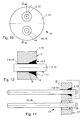
- the 4 to 6 show a second preferred embodiment of a fuze base 13, wherein the basic structure of the first preferred embodiment according to the Fig. 1 to 3 equivalent.
- the main body 14 of this second preferred embodiment likewise has a frustoconical first recess 4, wherein a receiving opening 9 is subsequently arranged on the bottom region 8 of the first recess 4.
- This receiving opening 9 has a substantially opposite to the first contact pin 15 cross section, wherein it is preferably provided that the receiving opening 9 has dimensions which allow insertion of the first contact pin 15 with a small clearance.
- the receiving opening 9 is formed as a blind hole. However, as shown, it is preferably provided that the receiving opening 9 is formed as a through-hole, whereby a particularly good connection between the first contact pin 15 and the main body 14 can be achieved.
- the first pin 2 and the first pin in the receiving opening 9 is arranged.
- the solder material 7 is arranged in a gap 10 between a pin skirt surface 11 of the first pin 2 and a second lateral surface of the receiving opening 9 in a gap 10 between a pin skirt surface 11 of the first pin 2 and a second lateral surface of the receiving opening 9 in a gap 10 between a pin skirt surface 11 of the first pin 2 and a second lateral surface of the receiving opening 9 at least partially the solder material 7 is arranged. This can be dispensed with a complex Vorbelöten the first pin 2 and the first contact pin 15, whereby a further processing step can be saved. It is preferably provided that the gap 10 is substantially completely filled with the solder material.
- the gap 10 has a width and a height which, in interaction with a certain solder material 7 and a specific processing temperature, results in the penetration of the solder material 7 into the gap 10 due to the capillary action.
- both the processing can be further simplified, and the safety of the solder joint can be increased, since the effective area of the solder joint is very large.
- the load capacity of the solder joint and the entire ignition base 13 can be improved.
- the security against destruction of the Zündersockels 13 - such as when igniting the gas generator - be improved.
- the first pin 2 arranged in the receiving opening 9 penetrates the main body 14.
- both the first and the second contact pin 15, 16 are flush with the first side 17 of the main body 14.
- the planar surface on the first side 17 is preferably achieved by grinding the base body 14 after the solder joint has been produced. The use of rounded end pins is therefore not limited in the second embodiment.
- Fig. 7 to 9 show a third preferred embodiment of a fuze base 13 for a gas generator, wherein the basic structure of the second preferred embodiment according to the 4 to 6 equivalent.
- a second recess is further provided on the first side 17, the use of which a second solder joint according to the invention is realized. Furthermore, the gap 10 is filled with solder 7. The ends of the two contact pins 15, 16 are unprocessed and have the production-related curves.
- the second recess forms at the edge of an annular elevation, which has a sharp edge.
- This preferably serves as a reservoir for a solder material 7, wherein it is preferably provided to abrade the edge and optionally the protruding parts of the first and / or second pin 2, 18 on the first side 17 in order to form a planar surface on the first side 17 ,
- the 10 to 12 show a fourth preferred embodiment of a fuze base 13, wherein the basic structure of the second preferred embodiment according to the 4 to 6 corresponds, wherein the first surface 3 is arranged on the first side 17, and project the ends of the two contact pins on this first surface 3.
- the solder joint according to the invention is therefore arranged only on the first side 17 of the base body 14.
- the parts of the first and / or second pin 2, 18 projecting on the first side 17 are ground to form a planar surface on the first side 17.
Landscapes
- Engineering & Computer Science (AREA)
- General Engineering & Computer Science (AREA)
- Connections Effected By Soldering, Adhesion, Or Permanent Deformation (AREA)
- Air Bags (AREA)
Applications Claiming Priority (1)
| Application Number | Priority Date | Filing Date | Title |
|---|---|---|---|
| AT16382010A AT510474B1 (de) | 2010-09-30 | 2010-09-30 | Lötverbindung |
Publications (2)
| Publication Number | Publication Date |
|---|---|
| EP2437352A1 true EP2437352A1 (fr) | 2012-04-04 |
| EP2437352B1 EP2437352B1 (fr) | 2017-03-08 |
Family
ID=45098998
Family Applications (1)
| Application Number | Title | Priority Date | Filing Date |
|---|---|---|---|
| EP11450127.3A Not-in-force EP2437352B1 (fr) | 2010-09-30 | 2011-09-29 | Liaison par brasage |
Country Status (2)
| Country | Link |
|---|---|
| EP (1) | EP2437352B1 (fr) |
| AT (1) | AT510474B1 (fr) |
Cited By (2)
| Publication number | Priority date | Publication date | Assignee | Title |
|---|---|---|---|---|
| AT513921A1 (de) * | 2013-01-23 | 2014-08-15 | Electrovac Hacht & Huber Gmbh | Zündersockel |
| AT513904A1 (de) * | 2013-01-23 | 2014-08-15 | Electrovac Hacht & Huber Gmbh | Zündersockel |
Families Citing this family (2)
| Publication number | Priority date | Publication date | Assignee | Title |
|---|---|---|---|---|
| DE102014219125A1 (de) * | 2014-09-23 | 2016-03-24 | Schott Ag | Durchführungselement mit direkt verbundenem Massestift, Verfahren zu seiner Herstellung und seine Verwendung |
| DE102014219127A1 (de) * | 2014-09-23 | 2016-03-24 | Schott Ag | Durchführungselement mit angeschweißtem Massestift, Verfahren zu seiner Herstellung und seine Verwendung |
Citations (2)
| Publication number | Priority date | Publication date | Assignee | Title |
|---|---|---|---|---|
| US3906858A (en) * | 1974-07-30 | 1975-09-23 | Us Eneregy Research And Dev Ad | Miniature igniter |
| US20100199872A1 (en) * | 2009-02-12 | 2010-08-12 | Schott Ag | Shaped feed-through element with contact rod soldered in |
Family Cites Families (6)
| Publication number | Priority date | Publication date | Assignee | Title |
|---|---|---|---|---|
| JP2778575B2 (ja) * | 1996-03-29 | 1998-07-23 | 日本電気株式会社 | プリント基板の接続方法 |
| JPH10321986A (ja) * | 1997-05-15 | 1998-12-04 | Oki Electric Ind Co Ltd | 部品実装構造 |
| FR2781878B1 (fr) * | 1998-07-31 | 2001-02-16 | Giat Ind Sa | Procede de mise en oeuvre d'une substance pyrotechnique et initiateur pyrotechnique obtenu avec un tel procede |
| DE19928320A1 (de) * | 1999-06-16 | 2001-01-04 | Siemens Ag | Elektrisch leitende Verbindung zwischen einer Endelektrode und einem Anschlußdraht |
| JP3473566B2 (ja) * | 2000-08-31 | 2003-12-08 | イビデン株式会社 | ピン立て型プリント回路基板 |
| US7124688B2 (en) * | 2000-12-08 | 2006-10-24 | Special Devices, Inc. | Overmolded body for pyrotechnic initiator and method of molding same |
-
2010
- 2010-09-30 AT AT16382010A patent/AT510474B1/de not_active IP Right Cessation
-
2011
- 2011-09-29 EP EP11450127.3A patent/EP2437352B1/fr not_active Not-in-force
Patent Citations (2)
| Publication number | Priority date | Publication date | Assignee | Title |
|---|---|---|---|---|
| US3906858A (en) * | 1974-07-30 | 1975-09-23 | Us Eneregy Research And Dev Ad | Miniature igniter |
| US20100199872A1 (en) * | 2009-02-12 | 2010-08-12 | Schott Ag | Shaped feed-through element with contact rod soldered in |
Cited By (5)
| Publication number | Priority date | Publication date | Assignee | Title |
|---|---|---|---|---|
| AT513921A1 (de) * | 2013-01-23 | 2014-08-15 | Electrovac Hacht & Huber Gmbh | Zündersockel |
| AT513904A1 (de) * | 2013-01-23 | 2014-08-15 | Electrovac Hacht & Huber Gmbh | Zündersockel |
| AT513904B1 (de) * | 2013-01-23 | 2014-11-15 | Electrovac Hacht & Huber Gmbh | Zündersockel |
| WO2014115026A3 (fr) * | 2013-01-23 | 2014-11-20 | Electrovac Hacht & Huber Gmbh | Socle d'amorçage |
| AT513921B1 (de) * | 2013-01-23 | 2015-05-15 | Electrovac Hacht & Huber Gmbh | Zündersockel |
Also Published As
| Publication number | Publication date |
|---|---|
| AT510474B1 (de) | 2013-11-15 |
| AT510474A1 (de) | 2012-04-15 |
| EP2437352B1 (fr) | 2017-03-08 |
Similar Documents
| Publication | Publication Date | Title |
|---|---|---|
| DE102009008673B3 (de) | Gestanztes Durchführungselement mit eingelötetem Kontaktstift | |
| EP2431703B1 (fr) | Traversée métal - matériau de fixation et son procédé de fabrication | |
| DE19925672B4 (de) | Zündkerze | |
| DE102010011150B4 (de) | Elektrische Sicherung für Kraftfahrzeugenergieleitungen und Herstellungsverfahren für eine solche Sicherung | |
| EP1455160A1 (fr) | Traversée métal-matériau de fixation et procédé de fabrication d'une tête d'initiateur avec traversée métal-matériau de fixation | |
| DE102007016692B3 (de) | Metall-Fixiermaterial-Durchführung | |
| DE102010045641A1 (de) | Verfahren zur Herstellung eines ring- oder plattenförmigen Elementes | |
| EP2270417A2 (fr) | Traversée métal - matériau de fixation et utilisation de celle-ci ainsi qu'airbag et tensionneur de ceinture avec initiateur | |
| EP2437352B1 (fr) | Liaison par brasage | |
| WO2016083557A1 (fr) | Élément de connexion, dispositif collecteur de courant et procédé de fabrication correspondant | |
| DE3415625C2 (fr) | ||
| DE102014219124B4 (de) | Durchführungselement mit Massepin in Kontakthülse, Verfahren zu seiner Herstellung und seine Verwendung | |
| DE2137990A1 (de) | Schutzeinrichtung fur elektrische Anlagen | |
| DE102010045624C5 (de) | Ring- oder plattenförmiges Element | |
| DE10327595A1 (de) | Zündkerze für eine Verbrennungskraftmaschine und Verfahren zu deren Herstellung | |
| DE102012223082A1 (de) | Kontaktelement und Verfahren zur Herstellung eines Kontaktelements | |
| DE102012100716B4 (de) | Herstellungsverfahren und Herstellungsvorrichtung für eine Zündkerze | |
| EP4218107B1 (fr) | Électrode de bougie d'allumage ainsi que bougie d'allumage pourvue de ladite électrode de bougie d'allumage et procédé de fabrication de ladite électrode de bougie d'allumage | |
| AT513905B1 (de) | Zündersockel | |
| AT513921B1 (de) | Zündersockel | |
| DE202013008375U1 (de) | Schmelzsicherung | |
| DE102024123605A1 (de) | Stromtrenner | |
| AT513904B1 (de) | Zündersockel | |
| DE3446799A1 (de) | Elektrisches zuend- oder anzuendelement | |
| DE102024118928A1 (de) | Batterie |
Legal Events
| Date | Code | Title | Description |
|---|---|---|---|
| PUAI | Public reference made under article 153(3) epc to a published international application that has entered the european phase |
Free format text: ORIGINAL CODE: 0009012 |
|
| AK | Designated contracting states |
Kind code of ref document: A1 Designated state(s): AL AT BE BG CH CY CZ DE DK EE ES FI FR GB GR HR HU IE IS IT LI LT LU LV MC MK MT NL NO PL PT RO RS SE SI SK SM TR |
|
| AX | Request for extension of the european patent |
Extension state: BA ME |
|
| 17P | Request for examination filed |
Effective date: 20121004 |
|
| GRAP | Despatch of communication of intention to grant a patent |
Free format text: ORIGINAL CODE: EPIDOSNIGR1 |
|
| RIC1 | Information provided on ipc code assigned before grant |
Ipc: H01R 33/06 20060101ALI20161004BHEP Ipc: H01R 4/02 20060101AFI20161004BHEP Ipc: F42B 3/103 20060101ALI20161004BHEP |
|
| INTG | Intention to grant announced |
Effective date: 20161020 |
|
| GRAS | Grant fee paid |
Free format text: ORIGINAL CODE: EPIDOSNIGR3 |
|
| GRAA | (expected) grant |
Free format text: ORIGINAL CODE: 0009210 |
|
| AK | Designated contracting states |
Kind code of ref document: B1 Designated state(s): AL AT BE BG CH CY CZ DE DK EE ES FI FR GB GR HR HU IE IS IT LI LT LU LV MC MK MT NL NO PL PT RO RS SE SI SK SM TR |
|
| REG | Reference to a national code |
Ref country code: GB Ref legal event code: FG4D Free format text: NOT ENGLISH |
|
| REG | Reference to a national code |
Ref country code: CH Ref legal event code: EP Ref country code: AT Ref legal event code: REF Ref document number: 874305 Country of ref document: AT Kind code of ref document: T Effective date: 20170315 |
|
| REG | Reference to a national code |
Ref country code: IE Ref legal event code: FG4D Free format text: LANGUAGE OF EP DOCUMENT: GERMAN |
|
| REG | Reference to a national code |
Ref country code: DE Ref legal event code: R096 Ref document number: 502011011788 Country of ref document: DE |
|
| REG | Reference to a national code |
Ref country code: CH Ref legal event code: NV Representative=s name: BOVARD AG PATENT- UND MARKENANWAELTE, CH |
|
| REG | Reference to a national code |
Ref country code: LT Ref legal event code: MG4D |
|
| REG | Reference to a national code |
Ref country code: NL Ref legal event code: MP Effective date: 20170308 |
|
| PG25 | Lapsed in a contracting state [announced via postgrant information from national office to epo] |
Ref country code: FI Free format text: LAPSE BECAUSE OF FAILURE TO SUBMIT A TRANSLATION OF THE DESCRIPTION OR TO PAY THE FEE WITHIN THE PRESCRIBED TIME-LIMIT Effective date: 20170308 Ref country code: NO Free format text: LAPSE BECAUSE OF FAILURE TO SUBMIT A TRANSLATION OF THE DESCRIPTION OR TO PAY THE FEE WITHIN THE PRESCRIBED TIME-LIMIT Effective date: 20170608 Ref country code: HR Free format text: LAPSE BECAUSE OF FAILURE TO SUBMIT A TRANSLATION OF THE DESCRIPTION OR TO PAY THE FEE WITHIN THE PRESCRIBED TIME-LIMIT Effective date: 20170308 Ref country code: LT Free format text: LAPSE BECAUSE OF FAILURE TO SUBMIT A TRANSLATION OF THE DESCRIPTION OR TO PAY THE FEE WITHIN THE PRESCRIBED TIME-LIMIT Effective date: 20170308 Ref country code: GR Free format text: LAPSE BECAUSE OF FAILURE TO SUBMIT A TRANSLATION OF THE DESCRIPTION OR TO PAY THE FEE WITHIN THE PRESCRIBED TIME-LIMIT Effective date: 20170609 |
|
| PG25 | Lapsed in a contracting state [announced via postgrant information from national office to epo] |
Ref country code: SE Free format text: LAPSE BECAUSE OF FAILURE TO SUBMIT A TRANSLATION OF THE DESCRIPTION OR TO PAY THE FEE WITHIN THE PRESCRIBED TIME-LIMIT Effective date: 20170308 Ref country code: BG Free format text: LAPSE BECAUSE OF FAILURE TO SUBMIT A TRANSLATION OF THE DESCRIPTION OR TO PAY THE FEE WITHIN THE PRESCRIBED TIME-LIMIT Effective date: 20170608 Ref country code: LV Free format text: LAPSE BECAUSE OF FAILURE TO SUBMIT A TRANSLATION OF THE DESCRIPTION OR TO PAY THE FEE WITHIN THE PRESCRIBED TIME-LIMIT Effective date: 20170308 Ref country code: RS Free format text: LAPSE BECAUSE OF FAILURE TO SUBMIT A TRANSLATION OF THE DESCRIPTION OR TO PAY THE FEE WITHIN THE PRESCRIBED TIME-LIMIT Effective date: 20170308 Ref country code: ES Free format text: LAPSE BECAUSE OF FAILURE TO SUBMIT A TRANSLATION OF THE DESCRIPTION OR TO PAY THE FEE WITHIN THE PRESCRIBED TIME-LIMIT Effective date: 20170308 |
|
| REG | Reference to a national code |
Ref country code: FR Ref legal event code: PLFP Year of fee payment: 7 |
|
| PG25 | Lapsed in a contracting state [announced via postgrant information from national office to epo] |
Ref country code: NL Free format text: LAPSE BECAUSE OF FAILURE TO SUBMIT A TRANSLATION OF THE DESCRIPTION OR TO PAY THE FEE WITHIN THE PRESCRIBED TIME-LIMIT Effective date: 20170308 |
|
| PG25 | Lapsed in a contracting state [announced via postgrant information from national office to epo] |
Ref country code: IT Free format text: LAPSE BECAUSE OF FAILURE TO SUBMIT A TRANSLATION OF THE DESCRIPTION OR TO PAY THE FEE WITHIN THE PRESCRIBED TIME-LIMIT Effective date: 20170308 Ref country code: RO Free format text: LAPSE BECAUSE OF FAILURE TO SUBMIT A TRANSLATION OF THE DESCRIPTION OR TO PAY THE FEE WITHIN THE PRESCRIBED TIME-LIMIT Effective date: 20170308 Ref country code: EE Free format text: LAPSE BECAUSE OF FAILURE TO SUBMIT A TRANSLATION OF THE DESCRIPTION OR TO PAY THE FEE WITHIN THE PRESCRIBED TIME-LIMIT Effective date: 20170308 Ref country code: SK Free format text: LAPSE BECAUSE OF FAILURE TO SUBMIT A TRANSLATION OF THE DESCRIPTION OR TO PAY THE FEE WITHIN THE PRESCRIBED TIME-LIMIT Effective date: 20170308 |
|
| PG25 | Lapsed in a contracting state [announced via postgrant information from national office to epo] |
Ref country code: PT Free format text: LAPSE BECAUSE OF FAILURE TO SUBMIT A TRANSLATION OF THE DESCRIPTION OR TO PAY THE FEE WITHIN THE PRESCRIBED TIME-LIMIT Effective date: 20170710 Ref country code: SM Free format text: LAPSE BECAUSE OF FAILURE TO SUBMIT A TRANSLATION OF THE DESCRIPTION OR TO PAY THE FEE WITHIN THE PRESCRIBED TIME-LIMIT Effective date: 20170308 Ref country code: PL Free format text: LAPSE BECAUSE OF FAILURE TO SUBMIT A TRANSLATION OF THE DESCRIPTION OR TO PAY THE FEE WITHIN THE PRESCRIBED TIME-LIMIT Effective date: 20170308 Ref country code: IS Free format text: LAPSE BECAUSE OF FAILURE TO SUBMIT A TRANSLATION OF THE DESCRIPTION OR TO PAY THE FEE WITHIN THE PRESCRIBED TIME-LIMIT Effective date: 20170708 |
|
| REG | Reference to a national code |
Ref country code: DE Ref legal event code: R097 Ref document number: 502011011788 Country of ref document: DE |
|
| PLBE | No opposition filed within time limit |
Free format text: ORIGINAL CODE: 0009261 |
|
| STAA | Information on the status of an ep patent application or granted ep patent |
Free format text: STATUS: NO OPPOSITION FILED WITHIN TIME LIMIT |
|
| PG25 | Lapsed in a contracting state [announced via postgrant information from national office to epo] |
Ref country code: DK Free format text: LAPSE BECAUSE OF FAILURE TO SUBMIT A TRANSLATION OF THE DESCRIPTION OR TO PAY THE FEE WITHIN THE PRESCRIBED TIME-LIMIT Effective date: 20170308 |
|
| 26N | No opposition filed |
Effective date: 20171211 |
|
| PG25 | Lapsed in a contracting state [announced via postgrant information from national office to epo] |
Ref country code: SI Free format text: LAPSE BECAUSE OF FAILURE TO SUBMIT A TRANSLATION OF THE DESCRIPTION OR TO PAY THE FEE WITHIN THE PRESCRIBED TIME-LIMIT Effective date: 20170308 |
|
| GBPC | Gb: european patent ceased through non-payment of renewal fee |
Effective date: 20170929 |
|
| PG25 | Lapsed in a contracting state [announced via postgrant information from national office to epo] |
Ref country code: MC Free format text: LAPSE BECAUSE OF FAILURE TO SUBMIT A TRANSLATION OF THE DESCRIPTION OR TO PAY THE FEE WITHIN THE PRESCRIBED TIME-LIMIT Effective date: 20170308 |
|
| REG | Reference to a national code |
Ref country code: IE Ref legal event code: MM4A |
|
| REG | Reference to a national code |
Ref country code: BE Ref legal event code: MM Effective date: 20170930 |
|
| PG25 | Lapsed in a contracting state [announced via postgrant information from national office to epo] |
Ref country code: LU Free format text: LAPSE BECAUSE OF NON-PAYMENT OF DUE FEES Effective date: 20170929 |
|
| PG25 | Lapsed in a contracting state [announced via postgrant information from national office to epo] |
Ref country code: GB Free format text: LAPSE BECAUSE OF NON-PAYMENT OF DUE FEES Effective date: 20170929 Ref country code: IE Free format text: LAPSE BECAUSE OF NON-PAYMENT OF DUE FEES Effective date: 20170929 |
|
| PG25 | Lapsed in a contracting state [announced via postgrant information from national office to epo] |
Ref country code: BE Free format text: LAPSE BECAUSE OF NON-PAYMENT OF DUE FEES Effective date: 20170930 |
|
| REG | Reference to a national code |
Ref country code: FR Ref legal event code: PLFP Year of fee payment: 8 |
|
| PG25 | Lapsed in a contracting state [announced via postgrant information from national office to epo] |
Ref country code: MT Free format text: LAPSE BECAUSE OF FAILURE TO SUBMIT A TRANSLATION OF THE DESCRIPTION OR TO PAY THE FEE WITHIN THE PRESCRIBED TIME-LIMIT Effective date: 20170308 |
|
| PG25 | Lapsed in a contracting state [announced via postgrant information from national office to epo] |
Ref country code: HU Free format text: LAPSE BECAUSE OF FAILURE TO SUBMIT A TRANSLATION OF THE DESCRIPTION OR TO PAY THE FEE WITHIN THE PRESCRIBED TIME-LIMIT; INVALID AB INITIO Effective date: 20110929 |
|
| PG25 | Lapsed in a contracting state [announced via postgrant information from national office to epo] |
Ref country code: CY Free format text: LAPSE BECAUSE OF NON-PAYMENT OF DUE FEES Effective date: 20170308 |
|
| PG25 | Lapsed in a contracting state [announced via postgrant information from national office to epo] |
Ref country code: MK Free format text: LAPSE BECAUSE OF FAILURE TO SUBMIT A TRANSLATION OF THE DESCRIPTION OR TO PAY THE FEE WITHIN THE PRESCRIBED TIME-LIMIT Effective date: 20170308 |
|
| PG25 | Lapsed in a contracting state [announced via postgrant information from national office to epo] |
Ref country code: TR Free format text: LAPSE BECAUSE OF FAILURE TO SUBMIT A TRANSLATION OF THE DESCRIPTION OR TO PAY THE FEE WITHIN THE PRESCRIBED TIME-LIMIT Effective date: 20170308 |
|
| PG25 | Lapsed in a contracting state [announced via postgrant information from national office to epo] |
Ref country code: AL Free format text: LAPSE BECAUSE OF FAILURE TO SUBMIT A TRANSLATION OF THE DESCRIPTION OR TO PAY THE FEE WITHIN THE PRESCRIBED TIME-LIMIT Effective date: 20170308 |
|
| PGFP | Annual fee paid to national office [announced via postgrant information from national office to epo] |
Ref country code: CH Payment date: 20200925 Year of fee payment: 10 |
|
| PGFP | Annual fee paid to national office [announced via postgrant information from national office to epo] |
Ref country code: AT Payment date: 20210910 Year of fee payment: 11 |
|
| REG | Reference to a national code |
Ref country code: CH Ref legal event code: PL |
|
| PG25 | Lapsed in a contracting state [announced via postgrant information from national office to epo] |
Ref country code: LI Free format text: LAPSE BECAUSE OF NON-PAYMENT OF DUE FEES Effective date: 20210930 Ref country code: CH Free format text: LAPSE BECAUSE OF NON-PAYMENT OF DUE FEES Effective date: 20210930 |
|
| PGFP | Annual fee paid to national office [announced via postgrant information from national office to epo] |
Ref country code: DE Payment date: 20220920 Year of fee payment: 12 Ref country code: CZ Payment date: 20220919 Year of fee payment: 12 |
|
| PGFP | Annual fee paid to national office [announced via postgrant information from national office to epo] |
Ref country code: FR Payment date: 20220920 Year of fee payment: 12 |
|
| REG | Reference to a national code |
Ref country code: AT Ref legal event code: MM01 Ref document number: 874305 Country of ref document: AT Kind code of ref document: T Effective date: 20220929 |
|
| P01 | Opt-out of the competence of the unified patent court (upc) registered |
Effective date: 20230515 |
|
| PG25 | Lapsed in a contracting state [announced via postgrant information from national office to epo] |
Ref country code: AT Free format text: LAPSE BECAUSE OF NON-PAYMENT OF DUE FEES Effective date: 20220929 |
|
| REG | Reference to a national code |
Ref country code: DE Ref legal event code: R119 Ref document number: 502011011788 Country of ref document: DE |
|
| PG25 | Lapsed in a contracting state [announced via postgrant information from national office to epo] |
Ref country code: CZ Free format text: LAPSE BECAUSE OF NON-PAYMENT OF DUE FEES Effective date: 20230929 |
|
| PG25 | Lapsed in a contracting state [announced via postgrant information from national office to epo] |
Ref country code: FR Free format text: LAPSE BECAUSE OF NON-PAYMENT OF DUE FEES Effective date: 20230930 Ref country code: DE Free format text: LAPSE BECAUSE OF NON-PAYMENT OF DUE FEES Effective date: 20240403 |