EP2437387A2 - Convertisseurs et inverseurs pour systèmes de puissance photovoltaïque - Google Patents
Convertisseurs et inverseurs pour systèmes de puissance photovoltaïque Download PDFInfo
- Publication number
- EP2437387A2 EP2437387A2 EP11175874A EP11175874A EP2437387A2 EP 2437387 A2 EP2437387 A2 EP 2437387A2 EP 11175874 A EP11175874 A EP 11175874A EP 11175874 A EP11175874 A EP 11175874A EP 2437387 A2 EP2437387 A2 EP 2437387A2
- Authority
- EP
- European Patent Office
- Prior art keywords
- converter
- voltage
- controller
- power
- output
- Prior art date
- Legal status (The legal status is an assumption and is not a legal conclusion. Google has not performed a legal analysis and makes no representation as to the accuracy of the status listed.)
- Withdrawn
Links
Images




Classifications
-
- H—ELECTRICITY
- H02—GENERATION; CONVERSION OR DISTRIBUTION OF ELECTRIC POWER
- H02M—APPARATUS FOR CONVERSION BETWEEN AC AND AC, BETWEEN AC AND DC, OR BETWEEN DC AND DC, AND FOR USE WITH MAINS OR SIMILAR POWER SUPPLY SYSTEMS; CONVERSION OF DC OR AC INPUT POWER INTO SURGE OUTPUT POWER; CONTROL OR REGULATION THEREOF
- H02M7/00—Conversion of AC power input into DC power output; Conversion of DC power input into AC power output
- H02M7/02—Conversion of AC power input into DC power output without possibility of reversal
- H02M7/04—Conversion of AC power input into DC power output without possibility of reversal by static converters
- H02M7/12—Conversion of AC power input into DC power output without possibility of reversal by static converters using discharge tubes with control electrode or semiconductor devices with control electrode
- H02M7/145—Conversion of AC power input into DC power output without possibility of reversal by static converters using discharge tubes with control electrode or semiconductor devices with control electrode using devices of a thyratron or thyristor type requiring extinguishing means
- H02M7/155—Conversion of AC power input into DC power output without possibility of reversal by static converters using discharge tubes with control electrode or semiconductor devices with control electrode using devices of a thyratron or thyristor type requiring extinguishing means using semiconductor devices only
- H02M7/17—Conversion of AC power input into DC power output without possibility of reversal by static converters using discharge tubes with control electrode or semiconductor devices with control electrode using devices of a thyratron or thyristor type requiring extinguishing means using semiconductor devices only arranged for operation in parallel
-
- H—ELECTRICITY
- H02—GENERATION; CONVERSION OR DISTRIBUTION OF ELECTRIC POWER
- H02J—ELECTRIC POWER NETWORKS; CIRCUIT ARRANGEMENTS OR SYSTEMS FOR SUPPLYING OR DISTRIBUTING ELECTRIC POWER; SYSTEMS FOR STORING ELECTRIC ENERGY
- H02J1/00—Circuit arrangements for DC mains or DC distribution networks
- H02J1/10—Parallel operation of DC sources
-
- H—ELECTRICITY
- H02—GENERATION; CONVERSION OR DISTRIBUTION OF ELECTRIC POWER
- H02J—ELECTRIC POWER NETWORKS; CIRCUIT ARRANGEMENTS OR SYSTEMS FOR SUPPLYING OR DISTRIBUTING ELECTRIC POWER; SYSTEMS FOR STORING ELECTRIC ENERGY
- H02J3/00—Circuit arrangements for AC mains or AC distribution networks
- H02J3/38—Arrangements for feeding a single network from two or more generators or sources in parallel; Arrangements for feeding already energised networks from additional generators or sources in parallel
-
- H—ELECTRICITY
- H02—GENERATION; CONVERSION OR DISTRIBUTION OF ELECTRIC POWER
- H02M—APPARATUS FOR CONVERSION BETWEEN AC AND AC, BETWEEN AC AND DC, OR BETWEEN DC AND DC, AND FOR USE WITH MAINS OR SIMILAR POWER SUPPLY SYSTEMS; CONVERSION OF DC OR AC INPUT POWER INTO SURGE OUTPUT POWER; CONTROL OR REGULATION THEREOF
- H02M3/00—Conversion of DC power input into DC power output
- H02M3/02—Conversion of DC power input into DC power output without intermediate conversion into AC
- H02M3/04—Conversion of DC power input into DC power output without intermediate conversion into AC by static converters
- H02M3/10—Conversion of DC power input into DC power output without intermediate conversion into AC by static converters using discharge tubes with control electrode or semiconductor devices with control electrode
- H02M3/145—Conversion of DC power input into DC power output without intermediate conversion into AC by static converters using discharge tubes with control electrode or semiconductor devices with control electrode using devices of a triode or transistor type requiring continuous application of a control signal
- H02M3/155—Conversion of DC power input into DC power output without intermediate conversion into AC by static converters using discharge tubes with control electrode or semiconductor devices with control electrode using devices of a triode or transistor type requiring continuous application of a control signal using semiconductor devices only
- H02M3/156—Conversion of DC power input into DC power output without intermediate conversion into AC by static converters using discharge tubes with control electrode or semiconductor devices with control electrode using devices of a triode or transistor type requiring continuous application of a control signal using semiconductor devices only with automatic control of output voltage or current, e.g. switching regulators
-
- H—ELECTRICITY
- H02—GENERATION; CONVERSION OR DISTRIBUTION OF ELECTRIC POWER
- H02M—APPARATUS FOR CONVERSION BETWEEN AC AND AC, BETWEEN AC AND DC, OR BETWEEN DC AND DC, AND FOR USE WITH MAINS OR SIMILAR POWER SUPPLY SYSTEMS; CONVERSION OF DC OR AC INPUT POWER INTO SURGE OUTPUT POWER; CONTROL OR REGULATION THEREOF
- H02M1/00—Details of apparatus for conversion
- H02M1/0067—Converter structures employing plural converter units, other than for parallel operation of the units on a single load
- H02M1/007—Plural converter units in cascade
-
- Y—GENERAL TAGGING OF NEW TECHNOLOGICAL DEVELOPMENTS; GENERAL TAGGING OF CROSS-SECTIONAL TECHNOLOGIES SPANNING OVER SEVERAL SECTIONS OF THE IPC; TECHNICAL SUBJECTS COVERED BY FORMER USPC CROSS-REFERENCE ART COLLECTIONS [XRACs] AND DIGESTS
- Y02—TECHNOLOGIES OR APPLICATIONS FOR MITIGATION OR ADAPTATION AGAINST CLIMATE CHANGE
- Y02E—REDUCTION OF GREENHOUSE GAS [GHG] EMISSIONS, RELATED TO ENERGY GENERATION, TRANSMISSION OR DISTRIBUTION
- Y02E10/00—Energy generation through renewable energy sources
- Y02E10/50—Photovoltaic [PV] energy
- Y02E10/56—Power conversion systems, e.g. maximum power point trackers
Definitions
- the present disclosure relates to photovoltaic power systems, DC/DC converters and DC/AC inverters for use in such systems, and related methods.
- PV devices convert sunlight to electricity.
- a PV device may consist of a single panel, multiple panels, rigid panels, flexible panels, serial panels, parallel panels, etc.
- the output of a PV device is typically unregulated (i.e. the output varies with changes in sunlight intensity, temperature, etc.). Further, the output of one PV device may differ from the output of another PV device due to manufacturing variations, different operating temperatures, unequal ageing, different positioning and/or mounting angles, different shading from trees, structures or clouds, different amounts of dirt or debris on the respective PV devices, etc.
- a power system includes a plurality of DC/DC converters and a DC/AC inverter.
- the plurality of DC/DC converters have outputs electrically connected in parallel for supplying a DC voltage bus to an input of the DC/AC inverter.
- each DC/DC converter includes a maximum power point tracker (MPPT).
- MPPT maximum power point tracker
- a DC/DC converter includes an input, an output, at least one power switch coupled between the input and the output, and a controller configured to provide a power delivery curve having a power-decreasing-with-voltage region.
- a DC/DC converter includes an input, an output, at least one power switch coupled between the input and the output, and a controller having a maximum power point tracker (MPPT).
- the controller is configured to run its MPPT when the output voltage of the DC/DC converter is pulled below a first voltage.
- a DC/DC converter includes an input, an output, at least one power switch coupled between the input and the output, and a high resistance path for limiting start-up current.
- a DC/AC inverter includes an input, an output, and a controller configured to maintain a voltage at the input within a defined voltage range.
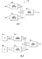
- Figure 1 is a block diagram of a system comprising a plurality of DC/DC converters for supplying power to a DC/AC inverter according to one example embodiment of the present disclosure.
- FIG. 2 is a block diagram of the system of Fig. 1 coupled to a plurality of photovoltaic (PV) panels according to another example embodiment.
- PV photovoltaic
- Figure 3 is a general block diagram of a DC/DC converter according to another example embodiment.
- Figure 4 illustrates example power delivery curves for the converter of Fig. 3 according to another example embodiment.
- Figure 5 illustrates additional example power delivery curves for the converter of Fig. 3 .
- Figure 6 is a block diagram of an example two-stage embodiment of the DC/DC converter of Fig. 3 .
- Figure 7 is a schematic diagram of a DC/DC converter according to another example embodiment of the present disclosure.
- Figure 8 is a block diagram of a system comprising a plurality of DC/DC converters for supplying a bus voltage to another DC/DC converter according to another example embodiment.
- Figure 9 is a block diagram of a system comprising a plurality of DC/DC converters for supplying a bus voltage to a DC bus according to yet another example embodiment.
- Figure 10 is a block diagram of a system comprising a plurality of DC/DC converters for supplying a bus voltage to one or more batteries according to still another example embodiment of the present disclosure.
- Example embodiments are provided so that this disclosure will be thorough, and will fully convey the scope to those who are skilled in the art. Numerous specific details are set forth such as examples of specific components, devices, and methods, to provide a thorough understanding of embodiments of the present disclosure. It will be apparent to those skilled in the art that specific details need not be employed, that example embodiments may be embodied in many different forms and that neither should be construed to limit the scope of the disclosure. In some example embodiments, well-known processes, well-known device structures, and well-known technologies are not described in detail.
- first, second, third, etc. may be used herein to describe various elements, components, regions, layers and/or sections, these elements, components, regions, layers and/or sections should not be limited by these terms. These terms may be only used to distinguish one element, component, region, layer or section from another region, layer or section. Terms such as “first,” “second,” and other numerical terms when used herein do not imply a sequence or order unless clearly indicated by the context. Thus, a first element, component, region, layer or section discussed below could be termed a second element, component, region, layer or section without departing from the teachings of the example embodiments.
- spatially relative terms such as “inner,” “outer,” “beneath,” “below,” “lower,” “above,” “upper,” and the like, may be used herein for ease of description to describe one element or feature's relationship to another element(s) or feature(s) as illustrated in the figures.
- Spatially relative terms may be intended to encompass different orientations of the device in use or operation in addition to the orientation depicted in the figures. For example, if the device in the figures is turned over, elements described as “below” or “beneath” other elements or features would then be oriented “above” the other elements or features.
- the example term “below” can encompass both an orientation of above and below.
- the device may be otherwise oriented (rotated 90 degrees or at other orientations) and the spatially relative descriptors used herein interpreted accordingly.
- FIG. 1 A system according to one example embodiment of the present disclosure is illustrated in Fig. 1 and indicated generally by reference number 100.
- the system 100 includes two DC/DC converters 102, 104 and a DC/AC inverter 106.
- Each DC/DC converter has an input 108, 110 for connection to an input power source.
- the converters also include outputs 112, 114 electrically connected in parallel to provide a DC voltage bus to an input 116 of the DC/AC inverter.
- the bus voltage may be fixed or variable.
- Each converter 102, 104 includes a maximum power point tracker (MPPT) that endeavors to harvest maximum power from its input power source. Additionally, each converter 102, 104 is preferably configured to operate independently of any external control signal (e.g., from a system controller or another DC/DC converter). The converters 102, 104 may be substantially identical to one another. Alternatively, converter 102 may be a different type and/or size than converter 104. In some embodiments, each converter is sized to match its input power source.
- MPPT maximum power point tracker
- the inverter 106 may be an isolated or non-isolated inverter.
- the inverter 106 is configured to control the bus voltage provided to its input 116.
- the inverter 116 may control the amount of current it draws from the converters to control the bus voltage.
- the inverter 106 may also include an MPPT (in addition to the converter MPPTs). If the inverter 106 does not include an MPPT (and even if it does), it is preferably configured to regulate its input voltage and/or current in a manner that is compatible with operation of the converter MPPTs (e.g., so the inverter presents a sufficient but not excessive load to the converters during normal operation). Further, the inverter 106 may be a grid-tie inverter (i.e., configured for connecting its output 118 to a utility power grid) or a non-grid-tie inverter (e.g., a residential inverter).
- converters 102, 104 are shown in Fig. 1 , it should be understood that less (i.e., one) or more converters may be used in other embodiments of this disclosure. Further, it should be understood that the converters 102, 104 may be used in other systems apart from the inverter 106, and the inverter 106 may be used in other systems apart from the converters 102, 104, without departing from the scope of this disclosure.
- the system 100 of Fig. 1 can be used with photovoltaic (PV) input power sources, as shown in Fig. 2 .
- the converter inputs 108, 110 may be coupled to photovoltaic (PV) panels 202, 204.
- Panel 202 may be a different type and/or size of panel than PV panel 204.
- the type and size of converters 102, 104 are preferably matched to the type and size of panels 202, 204, respectively.
- the flexibility to mix-and-match converters of various types and/or power ratings allows each DC/DC converter to be optimized for its input power source.
- Each converter may be physically mounted behind or near its associated PV panel. Alternatively, one or more converters may be located away from its panel, e.g., in a central area, etc.
- the MPPT in each converter 102, 104 adjusts its input voltage and/or input current as necessary to track the maximum power point (MPP) of its PV panel 202, 204 and thereby extract maximum power from the panels.
- the inverter 106 may also include an MPPT for maintaining the bus voltage and/or bus current at level(s) that maximize the amount of overall power extracted from the panels and converters as a group.
- the inverter 106 may be an off-the-shelf grid-tie solar inverter having an MPPT.
- the inverter 106 does not include a MPPT (and even if it does), the inverter is preferably configured to maintain its input voltage and/or input current at level(s) that do not interfere with operation of the converter MPPTs. For example, if each converter 102, 104 is configured to run its MPPT when the converter's output voltage is between 300 and 400 VDC, the inverter 106 may be configured to maintain its input voltage (i.e., the bus voltage) between 300 and 400 VDC. In this manner, the inverter 106 can maximize the amount of power harvested from the PV panels 202, 204 by the converters 102, 104.
- each converter 102, 104 is coupled to the output terminals of only one PV panel in the example of Fig. 2
- each converter may be coupled to series or parallel combination(s) of multiple PV panels in other embodiments of this disclosure.
- Fig. 3 illustrates a DC/DC converter 300 suitable for use as one of the converters 102, 104 in Figs. 1 and 2 .
- the DC/DC converter 300 includes an input 302, an output 304, a controller 306, passive components 308, and active components 310.
- the controller 306 is preferably a digital controller.
- the controller 306 is configured to operate one or more of the active components 310 (e.g. power switches, etc.) to control operation of the converter 300.
- the controller 306 is also configured to perform a MPPT method for tracking the maximum power point of an input power source coupled to the input 302.
- the controller 306 may be configured to adjust the duty cycle of one or more power switches as necessary to draw substantially maximum power from the input power source.
- Suitable MPPT methods include perturb-and-observe ("P & O"), constant input current regulation, constant input voltage regulation, predictive maximum power point tracking using defined characteristics of the input power source, etc).
- controller 306 need not be responsive to any external control signals (i.e., the controller may be configured to control operation of the converter 300 independently). In the example embodiment of Fig. 3 , the controller 306 is not responsive to any external control signals (e.g., from a central controller or another DC/DC converter).
- the converter 300 may include one or more power stages. Each stage may employ any suitable power conversion topology including buck, boost, buck-boost, etc. Additionally, one or more stages may be galvanically isolated (e.g., via an isolation transformer). The converter's MPPT may be implemented via the first and/or subsequent stages (when applicable) of the converter.
- the controller 306 may be configured (e.g., via software) to run its MPPT when the output voltage of the converter is pulled below a threshold level (e.g., by the load). For example, the controller may initially run an output voltage (or current) regulation mode. Subsequently, when the output voltage is pulled below the voltage regulation level (e.g., indicating the presence of a load), the controller may switch from the voltage regulation mode to an MPPT mode.
- a threshold level e.g., by the load.
- the controller may initially run an output voltage (or current) regulation mode. Subsequently, when the output voltage is pulled below the voltage regulation level (e.g., indicating the presence of a load), the controller may switch from the voltage regulation mode to an MPPT mode.
- the controller 306 may be configured to stop running its MPPT when, e.g., the output voltage returns (i.e., rises) to the voltage regulation level. In that event, the controller 306 may revert to the voltage regulation mode. In this manner, if a load (e.g., the inverter 106) stops accepting maximum power from the converter, the converter may stop supplying maximum power.
- a load e.g., the inverter 106
- the controller 306 may be configured to stop running the MPPT when the output voltage (or current) reaches a threshold level, such as a low voltage threshold.
- a threshold level such as a low voltage threshold.
- the controller will preferably stop running the MPPT when the output voltage of the converter (or another converter voltage) falls below a defined voltage to prevent high current damage to the converter.
- the controller may shutdown completely, disable one or more stages of the converter, revert to a voltage or current regulation mode, etc.
- the threshold levels e.g., voltage thresholds
- the threshold level(s) for one converter may be different than the threshold level(s) of one or more other converters.
- the voltage threshold levels of multiple converters may be staggered with respect to one another, so the converters start and/or stop delivering maximum power to the load in a defined sequence (e.g., one at a time, two at a time, etc.).
- one converter may start delivering maximum power when the bus voltage is pulled below 400 VDC
- another converter may start delivering maximum power when the bus voltage is pulled below 398 VDC, and so on.
- the controller 306 may be configured to provide a power-decreasing-with-voltage region.
- the converter may have one of the power delivery curves 400 shown in Fig. 4 .
- the example power delivery curves 400 include a power-decreasing-with-voltage region 402. In this region 402, the output power of the converter decreases as the output voltage decreases below 300 VDC.
- the example curves 400 (for various input power levels) also include a constant power region 404. In this region 404, the converter is running its MPPT so the output voltage of the converter increases as the output current decreases (and vice versa), assuming the power input to the converter is substantially constant.
- the transition between regions 402 and 404 is referred to as the knee voltage 406.
- the power-decreasing-with-voltage region 402 is particularly useful when the converter is coupled to an inverter having a MPPT. Because pulling the converter output voltage below 300 VDC will reduce rather than maximize the power input to the inverter, the inverter's MPPT will generally maintain the converter output voltage (e.g., the bus voltage in Figs. 1 and 2 ) above the knee voltage 406 (i.e., above 300 VDC in the example of Fig. 4 ).
- the output power of the converter decreases linearly as the output voltage decreases below the knee voltage 406.
- the output power may decrease nonlinearly.
- the converter 300 may have one of the power delivery curves 500 shown in Fig. 5 .
- the example power delivery curves 500 include a first power-decreasing-with-voltage region 502 and a second power-decreasing-with-voltage region 503, as well as a constant power region 504.
- the second region 503 has a greater slope than the first region 502.
- the power delivery curves 500 have a gentler transition from the constant power region 504 to the first power-decreasing-with-voltage region 502 (at the knee voltage 506) than from the first power-decreasing-with-voltage region 502 to the second power-decreasing-with-voltage region 503.
- Figs. 4 and 5 have power-decreasing-with-voltage regions that extend between zero and 300 VDC, it should be understood that other voltage ranges (including those that begin well above zero volts) and other power delivery curves may be employed in other embodiments of this disclosure.
- the power delivery curve(s) of the converter are preferably similar to the power delivery curve(s) of its PV panel.
- the converter will respond to the inverter (which may be a solar inverter designed for coupling directly to a PV panel) like a PV panel.
- the converter 300 may include a high current path to limit current flow under certain conditions, such as during start-up of the converter.
- the converter 300 may include two power stages as shown in Fig. 6 .
- the converter 300 may include a first power stage 602 coupled to a second power stage 604 by a resistor 606.
- a switch 608 may be connected in parallel with the resistor for selectively bypassing (i.e., electrically shorting) the resistor 606.
- the resistor limits the amount of current delivered to the second stage.
- the switch 608 is held open during start-up of the second stage 604.
- the resistor 606 provides a high resistance path that limits current.
- the switch 608 may be closed to bypass the resistor and allow increased current flow to the second stage (and the load).
- the switch 608 may be opened to limit current flow.
- the converter 300 may be configured to open the switch when the output voltage of the first stage 602 cannot be maintained above the input voltage of the first stage 602 (particularly if the first stage 602 employs a boost topology).
- the example circuit configuration of Fig. 6 protects the converter 300 from short circuit faults at its output (e.g., on the voltage bus of Figs. 1 and 2 ), as well as from damage that could otherwise result if the converter 300 is connected (e.g., in system 100) with the wrong polarity.
- the converter 300 may be configured to limit start-up current in other ways, to protect the converter and/or to prevent exceeding the current capacity of its input power source.
- the controller 306 may be configured to constrain the duty cycle of a power switch until the output voltage (or another parameter) of the converter reaches a threshold level.
- the converter 300 may include one or more diodes for preventing reverse current flow to a power source coupled to the input (such as PV panels 202, 204).
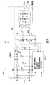
- Fig. 7 illustrates another example DC/DC converter 700 suitable for use as one of the converters 102, 104 in Figs. 1 and 2 .
- the DC/DC converter 700 includes an input 702, an output 704, and a switching power supply 706 coupled between the input 702 and the output 704.
- the switching power supply 706 is a two-stage boost converter that includes a first stage 708, a second stage 710, a controller 712, a switch Q2, and a resistor R2.
- the switch Q2 couples the first stage 708 to the second stage 710.
- the resistor R2 is connected in parallel with the switch Q2.
- the second stage 710 includes an isolation transformer TX1 and a diode bridge 714.
- the second stage 710 is an isolation bus converter stage that steps up the output voltage of the first stage 708 with galvanic isolation to a desired second voltage level. More specifically, the second stage 710 is a fixed frequency resonant half bridge converter configured for operating near boundary conduction mode. Zero voltage and zero current switching are also employed for high efficiency.
- the converter 700 of Fig. 7 may include one or more (e.g., all) of the features of converter 300 described above with reference to Figs. 3-6 .
- converter 700 An example operation of the converter 700 will now be described with reference to Figs. 2 and 7 .
- the converters 102, 104 in Fig. 2 each have the circuit configuration shown in Fig. 7 .
- two identical converters 700 are used as the converters 102, 104 in Fig. 2 .
- the following description will focus on converter 102 and PV panel 202, but may also apply to converter 104 and PV panel 204.
- the first stage 708 of converter 102 is configured to boost its input voltage to a level greater than the maximum open circuit voltage expected from its PV panel 202. Assuming the maximum open circuit voltage of panel 202 is 75V, the output voltage of the first stage 708 may be 80V. Assuming further the desired output voltage of the second stage 710 is 400 V, the second stage requires a 1:5 boost ratio.
- an internal auxiliary power converter (not shown in Fig. 7 ) will start up to generate internal bias voltages for the converter 102. If the PV panel 202 does not produce sufficient power to start the low power auxiliary converter for biasing, the auxiliary converter will continue its attempts to turn on. When the panel 202 produces sufficient energy to start the auxiliary converter (to power the controller 712), the controller 712 will attempt to start the first stage 708. If the panel 202 does not produce sufficient power to sustain the minimum no load power of the first stage 708, repeated attempts may be made. This behavior is expected at dawn, when radiation increases with the rising sun. At some point, the first stage 708 will start up and deliver a regulated output voltage of 80V at no load. During this time, switch Q2 is disabled (i.e., open) and the second stage 710 is disabled.
- the second stage is enabled. Initially, switch Q2 is held off (i.e., open) so the second stage 710 receives only limited power due to the resistor R2. During this time, a PV input voltage regulation loop may be activated to ensure the voltage provided by the panel 202 does not slip to zero.
- the regulated input voltage level may be, for example, 70% of the input voltage observed before the second stage 710 was enabled. The 70% level may be used if the MPP voltage of panel 202 is between 75% to 85% of its open circuit voltage. Alternatively, another input voltage regulation level may be employed.
- the inverter 106 may include a large bulk capacitance that will create a near short-circuit on the output 704 of the converter 102 during the power-up cycle. Also, other DC/DC converters connected in parallel with converter 102 (including converter 104) may not start at the same time. Due to the series insertion of R2, the output voltage of the second stage 710 will rise slowly, allowing the controller 712 to identify the nature of the load. The voltage at the output 704 is reflected across capacitor C3 where it may be monitored by the controller 712. As this voltage rises and exceeds the 70% clamp level set for controlling the input voltage, the switch Q2 is turned on. Now more energy can be supplied to charge the load capacitance as the current limit resistor R2 has been bypassed.
- the controller's MPPT is activated to monitor the PV input current and voltage and operate as close to the MPP as possible.
- the current limit network of switch Q2 and resistor R2 also protects the converter 700 from short circuit faults on the output 704 and may prevent damage if the converter 700 is connected with wrong polarity.
- the current limit network may prevent the destruction of the converter connected in wrong polarity as other parallel converters will see a short circuit and may operate in current limit mode.
- Each converter may eventually disable itself if the control circuit observes that the output bus voltage is not able to rise in preset time duration.
- the second stage 710 includes an isolation transformer TX1 which galvanically isolates the input 702 from the output 704. Further, the second stage 710 includes a diode bridge 714 which prevents current from flowing from the output 704 to the input 702.
- the inverter 106 in Figs. 1 and 2 can be omitted and/or replaced by another component.
- the inverter 106 can be replaced by a DC/DC converter (as shown in Fig. 8 ), e.g., for reducing or increasing the DC bus voltage level.
- the inverter 106 may be omitted so the DC bus voltage provided by the converters 102, 104 may be coupled to a DC bus (e.g., a 48V or 400V bus in a DC power distribution system), as shown in Fig. 9 .
- the converters 102, 104 may be either the sole or a supplemental power source for the DC bus.
- the inverter 106 may be omitted so the DC bus voltage provided by the converters 102, 104 may be coupled to one or more batteries (including a battery bank), as shown in Fig. 10 .
- the DC bus voltage provided by the converters 102, 104 is preferably slightly greater than any grid fed battery charger so, e.g., power is drawn from the PV panels 202, 204 first, and then from the utility grid.
- the devices and methods of the present disclosure are not limited to photovoltaic applications.
- the devices and methods of the present disclosure may be used with other distributed power applications.
Landscapes
- Engineering & Computer Science (AREA)
- Power Engineering (AREA)
- Dc-Dc Converters (AREA)
- Inverter Devices (AREA)
- Control Of Electrical Variables (AREA)
- Supply And Distribution Of Alternating Current (AREA)
Applications Claiming Priority (2)
| Application Number | Priority Date | Filing Date | Title |
|---|---|---|---|
| US38841710P | 2010-09-30 | 2010-09-30 | |
| US12/976,544 US8576591B2 (en) | 2010-09-30 | 2010-12-22 | Converters and inverters for photovoltaic power systems |
Publications (2)
| Publication Number | Publication Date |
|---|---|
| EP2437387A2 true EP2437387A2 (fr) | 2012-04-04 |
| EP2437387A3 EP2437387A3 (fr) | 2018-04-18 |
Family
ID=44658609
Family Applications (1)
| Application Number | Title | Priority Date | Filing Date |
|---|---|---|---|
| EP11175874.4A Withdrawn EP2437387A3 (fr) | 2010-09-30 | 2011-07-28 | Convertisseurs et inverseurs pour systèmes de puissance photovoltaïque |
Country Status (3)
| Country | Link |
|---|---|
| US (3) | US8576591B2 (fr) |
| EP (1) | EP2437387A3 (fr) |
| CN (1) | CN102447384B (fr) |
Cited By (11)
| Publication number | Priority date | Publication date | Assignee | Title |
|---|---|---|---|---|
| DE102012017461A1 (de) * | 2012-09-04 | 2014-03-06 | Michael Klemt | Schaltungsanordnung für eine Energieversorgung mit einem Solargenerator als Energiequelle und einer Batterie zum Speichern der Energie und ein Verfahren zum Betrieb einer solchen Schaltungsanordnung |
| EP2775531A1 (fr) * | 2013-03-07 | 2014-09-10 | ABB Oy | Procédé et dispositif pour faire fonctionner un système photovoltaïque et système photovoltaïque |
| WO2015052052A1 (fr) * | 2013-10-07 | 2015-04-16 | Sma Solar Technology Ag | Onduleur photovoltaïque multibranches avec détection de convertisseurs continu-continu intercalés pour désactiver le contrôleur mppt interne |
| GB2523226A (en) * | 2013-12-10 | 2015-08-19 | Sma Solar Technology Ag | Photovoltaic system and method for operating a photovoltaic system |
| EP3324507A1 (fr) * | 2014-07-23 | 2018-05-23 | DET International Holding Limited | Compensation d'impédance |
| CN112491032A (zh) * | 2019-09-12 | 2021-03-12 | 阳光电源股份有限公司 | 一种直流耦合离网制氢系统及其控制方法 |
| US11451052B2 (en) | 2018-05-04 | 2022-09-20 | Nextracker Llc | Systems and methods of DC power conversion and transmission for solar fields |
| WO2023066485A1 (fr) * | 2021-10-21 | 2023-04-27 | Huawei Digital Power Technologies Co., Ltd. | Système de conversion de puissance pour connecter une installation photovoltaïque à une grille électrique |
| EP4250557A4 (fr) * | 2020-12-22 | 2024-02-07 | Huawei Digital Power Technologies Co., Ltd. | Système de génération d'énergie photovoltaïque, procédé de commande de puissance et boîtier combinateur |
| US12224703B2 (en) | 2020-07-29 | 2025-02-11 | Nextracker Llc | Fixed DC bus and hydrogen generation system |
| EP4718707A1 (fr) * | 2024-09-26 | 2026-04-01 | Huawei Digital Power Technologies Co., Ltd. | Onduleur et procédé de commande d'onduleur |
Families Citing this family (109)
| Publication number | Priority date | Publication date | Assignee | Title |
|---|---|---|---|---|
| US11881814B2 (en) | 2005-12-05 | 2024-01-23 | Solaredge Technologies Ltd. | Testing of a photovoltaic panel |
| US10693415B2 (en) | 2007-12-05 | 2020-06-23 | Solaredge Technologies Ltd. | Testing of a photovoltaic panel |
| US8405367B2 (en) | 2006-01-13 | 2013-03-26 | Enecsys Limited | Power conditioning units |
| US8816535B2 (en) | 2007-10-10 | 2014-08-26 | Solaredge Technologies, Ltd. | System and method for protection during inverter shutdown in distributed power installations |
| US11735910B2 (en) | 2006-12-06 | 2023-08-22 | Solaredge Technologies Ltd. | Distributed power system using direct current power sources |
| US11309832B2 (en) | 2006-12-06 | 2022-04-19 | Solaredge Technologies Ltd. | Distributed power harvesting systems using DC power sources |
| US12316274B2 (en) | 2006-12-06 | 2025-05-27 | Solaredge Technologies Ltd. | Pairing of components in a direct current distributed power generation system |
| US8319471B2 (en) | 2006-12-06 | 2012-11-27 | Solaredge, Ltd. | Battery power delivery module |
| US11855231B2 (en) | 2006-12-06 | 2023-12-26 | Solaredge Technologies Ltd. | Distributed power harvesting systems using DC power sources |
| US11687112B2 (en) | 2006-12-06 | 2023-06-27 | Solaredge Technologies Ltd. | Distributed power harvesting systems using DC power sources |
| US9112379B2 (en) | 2006-12-06 | 2015-08-18 | Solaredge Technologies Ltd. | Pairing of components in a direct current distributed power generation system |
| US8319483B2 (en) | 2007-08-06 | 2012-11-27 | Solaredge Technologies Ltd. | Digital average input current control in power converter |
| US8013472B2 (en) | 2006-12-06 | 2011-09-06 | Solaredge, Ltd. | Method for distributed power harvesting using DC power sources |
| US8963369B2 (en) | 2007-12-04 | 2015-02-24 | Solaredge Technologies Ltd. | Distributed power harvesting systems using DC power sources |
| US9130401B2 (en) | 2006-12-06 | 2015-09-08 | Solaredge Technologies Ltd. | Distributed power harvesting systems using DC power sources |
| US8473250B2 (en) | 2006-12-06 | 2013-06-25 | Solaredge, Ltd. | Monitoring of distributed power harvesting systems using DC power sources |
| US11296650B2 (en) | 2006-12-06 | 2022-04-05 | Solaredge Technologies Ltd. | System and method for protection during inverter shutdown in distributed power installations |
| US8947194B2 (en) | 2009-05-26 | 2015-02-03 | Solaredge Technologies Ltd. | Theft detection and prevention in a power generation system |
| US11888387B2 (en) | 2006-12-06 | 2024-01-30 | Solaredge Technologies Ltd. | Safety mechanisms, wake up and shutdown methods in distributed power installations |
| US8618692B2 (en) | 2007-12-04 | 2013-12-31 | Solaredge Technologies Ltd. | Distributed power system using direct current power sources |
| US9088178B2 (en) | 2006-12-06 | 2015-07-21 | Solaredge Technologies Ltd | Distributed power harvesting systems using DC power sources |
| US8384243B2 (en) | 2007-12-04 | 2013-02-26 | Solaredge Technologies Ltd. | Distributed power harvesting systems using DC power sources |
| US11569659B2 (en) | 2006-12-06 | 2023-01-31 | Solaredge Technologies Ltd. | Distributed power harvesting systems using DC power sources |
| EP3496258B1 (fr) | 2007-12-05 | 2025-02-05 | Solaredge Technologies Ltd. | Mécanismes de sécurité dans des installations de puissance réparties |
| US8049523B2 (en) | 2007-12-05 | 2011-11-01 | Solaredge Technologies Ltd. | Current sensing on a MOSFET |
| EP2232690B1 (fr) | 2007-12-05 | 2016-08-31 | Solaredge Technologies Ltd. | Onduleurs connectés en parallèle |
| US11264947B2 (en) | 2007-12-05 | 2022-03-01 | Solaredge Technologies Ltd. | Testing of a photovoltaic panel |
| EP4145691A1 (fr) | 2008-03-24 | 2023-03-08 | Solaredge Technologies Ltd. | Convertisseur à découpage avec circuit auxiliaire de commutation par courant nul |
| EP3121922B1 (fr) | 2008-05-05 | 2020-03-04 | Solaredge Technologies Ltd. | Combineur de puissance en courant continu |
| US12418177B2 (en) | 2009-10-24 | 2025-09-16 | Solaredge Technologies Ltd. | Distributed power system using direct current power sources |
| CN201563081U (zh) * | 2009-10-30 | 2010-08-25 | 国琏电子(上海)有限公司 | 太阳能转换模块及使用其的供电系统 |
| US9142960B2 (en) * | 2010-02-03 | 2015-09-22 | Draker, Inc. | Constraint weighted regulation of DC/DC converters |
| GB2482653B (en) | 2010-06-07 | 2012-08-29 | Enecsys Ltd | Solar photovoltaic systems |
| US10230310B2 (en) | 2016-04-05 | 2019-03-12 | Solaredge Technologies Ltd | Safety switch for photovoltaic systems |
| GB2485527B (en) | 2010-11-09 | 2012-12-19 | Solaredge Technologies Ltd | Arc detection and prevention in a power generation system |
| US10673229B2 (en) | 2010-11-09 | 2020-06-02 | Solaredge Technologies Ltd. | Arc detection and prevention in a power generation system |
| US10673222B2 (en) | 2010-11-09 | 2020-06-02 | Solaredge Technologies Ltd. | Arc detection and prevention in a power generation system |
| GB2486408A (en) | 2010-12-09 | 2012-06-20 | Solaredge Technologies Ltd | Disconnection of a string carrying direct current |
| GB2496140B (en) | 2011-11-01 | 2016-05-04 | Solarcity Corp | Photovoltaic power conditioning units |
| GB2483317B (en) | 2011-01-12 | 2012-08-22 | Solaredge Technologies Ltd | Serially connected inverters |
| GB2487368B (en) | 2011-01-18 | 2012-12-05 | Enecsys Ltd | Inverters |
| US8716999B2 (en) * | 2011-02-10 | 2014-05-06 | Draker, Inc. | Dynamic frequency and pulse-width modulation of dual-mode switching power controllers in photovoltaic arrays |
| GB2486509B (en) | 2011-03-22 | 2013-01-09 | Enecsys Ltd | Solar photovoltaic power conditioning units |
| US8937822B2 (en) | 2011-05-08 | 2015-01-20 | Paul Wilkinson Dent | Solar energy conversion and utilization system |
| US11901810B2 (en) | 2011-05-08 | 2024-02-13 | Koolbridge Solar, Inc. | Adaptive electrical power distribution panel |
| US12362647B2 (en) | 2011-05-08 | 2025-07-15 | Koolbridge Solar, Inc. | Solar energy system with variable priority circuit backup |
| FR2976745B1 (fr) * | 2011-06-15 | 2015-07-17 | Schneider Electric Ind Sas | Mecanisme de commande securise pour systeme photovoltaique distribue |
| CN102931862A (zh) * | 2011-08-12 | 2013-02-13 | 旭丽电子(广州)有限公司 | 直流-交流转换系统及直流-交流转换电路 |
| US8570005B2 (en) | 2011-09-12 | 2013-10-29 | Solaredge Technologies Ltd. | Direct current link circuit |
| US8472219B2 (en) * | 2011-09-14 | 2013-06-25 | General Electric Company | Method and systems for converting power |
| GB2496139B (en) | 2011-11-01 | 2016-05-04 | Solarcity Corp | Photovoltaic power conditioning units |
| KR101310551B1 (ko) * | 2011-11-11 | 2013-09-23 | 성균관대학교산학협력단 | 컨버터, 컨버터 제어방법 및 인버터 |
| GB2498365A (en) | 2012-01-11 | 2013-07-17 | Solaredge Technologies Ltd | Photovoltaic module |
| US9853565B2 (en) | 2012-01-30 | 2017-12-26 | Solaredge Technologies Ltd. | Maximized power in a photovoltaic distributed power system |
| GB2498790A (en) | 2012-01-30 | 2013-07-31 | Solaredge Technologies Ltd | Maximising power in a photovoltaic distributed power system |
| GB2498791A (en) | 2012-01-30 | 2013-07-31 | Solaredge Technologies Ltd | Photovoltaic panel circuitry |
| GB2499991A (en) | 2012-03-05 | 2013-09-11 | Solaredge Technologies Ltd | DC link circuit for photovoltaic array |
| US10411477B2 (en) * | 2012-03-26 | 2019-09-10 | Pika Energy, Inc. | Distributed substring architecture for maximum power point tracking of energy sources |
| US10115841B2 (en) * | 2012-06-04 | 2018-10-30 | Solaredge Technologies Ltd. | Integrated photovoltaic panel circuitry |
| EP2683066B1 (fr) * | 2012-07-04 | 2017-05-03 | DET International Holding Limited | Équilibrage de LLC |
| US9024609B2 (en) * | 2012-07-11 | 2015-05-05 | Pai Capital Llc | Circuit and method for providing hold-up time in a DC-DC converter |
| CN102832842A (zh) * | 2012-08-31 | 2012-12-19 | 广东明阳龙源电力电子有限公司 | 一种新型三相光伏并网逆变器系统 |
| US9219363B2 (en) * | 2012-09-06 | 2015-12-22 | Eaton Corporation | Photovoltaic system and method employing a number of maximum power point tracking mechanisms |
| CN102931679A (zh) * | 2012-10-12 | 2013-02-13 | 吴加林 | 多级升压大功率光伏并网电站 |
| TWI469471B (zh) * | 2012-11-23 | 2015-01-11 | Univ Nat Sun Yat Sen | 具最大功率追蹤之脈衝式充電電路及其充電方法 |
| CN103034278A (zh) * | 2012-12-11 | 2013-04-10 | 易霸科技(威海)股份有限公司 | 基于双重线性近似值的mppt算法的模拟电路实现方法 |
| US9559516B2 (en) * | 2013-03-13 | 2017-01-31 | Astec International Limited | Arc prevention in DC power systems |
| US9548619B2 (en) | 2013-03-14 | 2017-01-17 | Solaredge Technologies Ltd. | Method and apparatus for storing and depleting energy |
| EP2779251B1 (fr) | 2013-03-15 | 2019-02-27 | Solaredge Technologies Ltd. | Mécanisme de dérivation |
| US9450496B2 (en) * | 2013-04-11 | 2016-09-20 | Astec International Limited | Multi-stage power converters and methods for varying a regulated voltage of one stage as a function of an output current of another stage |
| EP3026521B1 (fr) * | 2013-07-26 | 2021-11-24 | Kyocera Corporation | Dispositif de conversion de puissance, procédé de gestion de l'énergie et programme de gestion de l'énergie |
| CN105830284B (zh) * | 2013-12-06 | 2020-09-15 | 安费诺富加宜(亚洲)私人有限公司 | 用于电力连接的电缆组件 |
| CN104811036B (zh) * | 2014-01-28 | 2018-01-26 | 台达电子企业管理(上海)有限公司 | 多电源供电系统及其控制方法 |
| US9223741B1 (en) | 2014-10-17 | 2015-12-29 | Lexmark International, Inc. | Systems for setting the address of a module |
| AU2015364718B2 (en) | 2014-12-16 | 2019-11-28 | Marici Holdings The Netherlands B.V. | Energy panel arrangement power dissipation |
| US10348094B2 (en) | 2015-01-28 | 2019-07-09 | Abb Schweiz Ag | Energy panel arrangement shutdown |
| KR20160098894A (ko) * | 2015-02-11 | 2016-08-19 | 삼성에스디아이 주식회사 | 전력 변환 장치 및 그의 구동 방법 |
| WO2016134356A1 (fr) | 2015-02-22 | 2016-08-25 | Abb Technology Ag | Détection de polarité inverse dans une suite de cellules photovoltaïques |
| WO2016140844A1 (fr) | 2015-03-03 | 2016-09-09 | Fci Asia Pte. Ltd | Connecteur dénudant |
| US10256732B2 (en) | 2015-10-16 | 2019-04-09 | General Electric Company | Power conversion system and method of operating the same |
| WO2017087988A1 (fr) * | 2015-11-19 | 2017-05-26 | Beamreach Solar, Inc. | Système photovoltaïque solaire à optimisation de suivi de point de puissance maximal multimodal |
| US11611220B2 (en) * | 2015-12-31 | 2023-03-21 | Present Power Systems, Llc | Systems and methods for connecting energy sources to power distribution network |
| US11081608B2 (en) | 2016-03-03 | 2021-08-03 | Solaredge Technologies Ltd. | Apparatus and method for determining an order of power devices in power generation systems |
| US10599113B2 (en) | 2016-03-03 | 2020-03-24 | Solaredge Technologies Ltd. | Apparatus and method for determining an order of power devices in power generation systems |
| CN107153212B (zh) | 2016-03-03 | 2023-07-28 | 太阳能安吉科技有限公司 | 用于映射发电设施的方法 |
| US11177663B2 (en) | 2016-04-05 | 2021-11-16 | Solaredge Technologies Ltd. | Chain of power devices |
| US12057807B2 (en) | 2016-04-05 | 2024-08-06 | Solaredge Technologies Ltd. | Chain of power devices |
| US11018623B2 (en) | 2016-04-05 | 2021-05-25 | Solaredge Technologies Ltd. | Safety switch for photovoltaic systems |
| JP6724681B2 (ja) * | 2016-09-20 | 2020-07-15 | オムロン株式会社 | 分散型電源システム及びdc/dcコンバータ |
| TWI614963B (zh) * | 2016-09-21 | 2018-02-11 | 台達電子工業股份有限公司 | 電源轉換模組、發電系統及其控制方法 |
| US10395867B2 (en) * | 2016-09-21 | 2019-08-27 | William Atchison | Self regulating mechanism for storage water heater |
| US11309714B2 (en) | 2016-11-02 | 2022-04-19 | Tesla, Inc. | Micro-batteries for energy generation systems |
| US10239088B2 (en) * | 2017-03-22 | 2019-03-26 | Ford Motor Company | Fluid application system adapted to collect and reuse reclaimed fluid |
| BR102017020419A2 (pt) * | 2017-09-25 | 2018-01-30 | Votorantim Metais Zinco S/A | Sistema híbrido de geração e alimentação de energia eletrica empregado em processo de eletrólise para obtenção de metais não ferrosos |
| US11502533B2 (en) | 2019-02-13 | 2022-11-15 | Intrinsix Corp. | Power conveyor devices for energy harvesting systems and methods thereof |
| CN110391676B (zh) * | 2019-08-09 | 2021-07-20 | 阳光电源股份有限公司 | 一种多路mppt逆变器及其控制方法 |
| KR102245969B1 (ko) * | 2019-11-21 | 2021-04-29 | 연세대학교 산학협력단 | 태양광 발전 시스템의 일정 출력 제어를 위한 장치 및 방법 |
| US11764679B2 (en) | 2020-01-15 | 2023-09-19 | Solaredge Technologies Ltd. | Power device |
| US12362713B2 (en) * | 2021-02-15 | 2025-07-15 | Texas Instruments Incorporated | Maximum power detection and automatic gain control for capacitive class-D amplifiers |
| US12034301B2 (en) | 2021-07-09 | 2024-07-09 | Unico, Llc | Multi-way power controller and related methods |
| JP7578087B2 (ja) | 2021-09-30 | 2024-11-06 | トヨタ自動車株式会社 | 発電装置 |
| CN114567018A (zh) * | 2022-03-08 | 2022-05-31 | 广州菲利斯太阳能科技有限公司 | 一种多路mppt的并网逆变器及逆变器控制方法 |
| US12360167B2 (en) | 2022-05-11 | 2025-07-15 | Unico, Llc | Energy storage system and method of control |
| US12483136B2 (en) * | 2022-11-04 | 2025-11-25 | University Of North Texas | Multiple port bidirectional power conversion circuit |
| KR102741910B1 (ko) * | 2022-12-27 | 2024-12-16 | 한국전자기술연구원 | 공진형 전력변환장치의 전력 불평형 방지 회로 및 방법 |
| JP2026502230A (ja) * | 2022-12-30 | 2026-01-21 | ティーエーイー テクノロジーズ, インコーポレイテッド | パルス電力アプリケーションのための電力供給装置 |
| CN116231738A (zh) * | 2023-02-23 | 2023-06-06 | 华为数字能源技术有限公司 | 功率变换装置和控制方法 |
| CN116454980B (zh) * | 2023-06-15 | 2023-09-01 | 麦田能源股份有限公司 | 电源变换装置及最大功率点跟踪控制方法 |
| CN121173117B (zh) * | 2025-11-20 | 2026-03-31 | 深圳市首航新能源股份有限公司 | 一种pv输入通道识别方法、装置和电子设备 |
Citations (1)
| Publication number | Priority date | Publication date | Assignee | Title |
|---|---|---|---|---|
| WO2009140536A2 (fr) * | 2008-05-14 | 2009-11-19 | National Semiconductor Corporation | Procédé et système permettant de localiser un point de puissance maximum dans un système de production d'énergie |
Family Cites Families (34)
| Publication number | Priority date | Publication date | Assignee | Title |
|---|---|---|---|---|
| US4404472A (en) | 1981-12-28 | 1983-09-13 | General Electric Company | Maximum power control for a solar array connected to a load |
| US4604567A (en) * | 1983-10-11 | 1986-08-05 | Sundstrand Corporation | Maximum power transfer system for a solar cell array |
| JP2000112545A (ja) | 1998-09-30 | 2000-04-21 | Daihen Corp | 太陽光発電システム |
| US6127621A (en) | 1999-04-02 | 2000-10-03 | The Aerospace Corporation | Power sphere |
| JP4115629B2 (ja) * | 1999-05-25 | 2008-07-09 | 本田技研工業株式会社 | 電力供給システム |
| JP2001255949A (ja) * | 2000-03-13 | 2001-09-21 | Toshiba Corp | 太陽光発電インバータ装置 |
| JP3707436B2 (ja) * | 2002-01-25 | 2005-10-19 | 株式会社村田製作所 | スイッチング電源装置 |
| US7087332B2 (en) * | 2002-07-31 | 2006-08-08 | Sustainable Energy Systems, Inc. | Power slope targeting for DC generators |
| US6966184B2 (en) | 2002-11-25 | 2005-11-22 | Canon Kabushiki Kaisha | Photovoltaic power generating apparatus, method of producing same and photovoltaic power generating system |
| US7403400B2 (en) * | 2003-07-24 | 2008-07-22 | Harman International Industries, Incorporated | Series interleaved boost converter power factor correcting power supply |
| US7161331B2 (en) * | 2005-04-11 | 2007-01-09 | Yuan Ze University | Boost converter utilizing bi-directional magnetic energy transfer of coupling inductor |
| US7324354B2 (en) * | 2005-07-08 | 2008-01-29 | Bio-Rad Laboratories, Inc. | Power supply with a digital feedback loop |
| GB2454389B (en) * | 2006-01-13 | 2009-08-26 | Enecsys Ltd | Power conditioning unit |
| US8751053B2 (en) | 2006-10-19 | 2014-06-10 | Tigo Energy, Inc. | Method and system to provide a distributed local energy production system with high-voltage DC bus |
| US8013472B2 (en) | 2006-12-06 | 2011-09-06 | Solaredge, Ltd. | Method for distributed power harvesting using DC power sources |
| US9088178B2 (en) | 2006-12-06 | 2015-07-21 | Solaredge Technologies Ltd | Distributed power harvesting systems using DC power sources |
| US20080144294A1 (en) | 2006-12-06 | 2008-06-19 | Meir Adest | Removal component cartridge for increasing reliability in power harvesting systems |
| US8319471B2 (en) | 2006-12-06 | 2012-11-27 | Solaredge, Ltd. | Battery power delivery module |
| US8473250B2 (en) | 2006-12-06 | 2013-06-25 | Solaredge, Ltd. | Monitoring of distributed power harvesting systems using DC power sources |
| US7900361B2 (en) | 2006-12-06 | 2011-03-08 | Solaredge, Ltd. | Current bypass for distributed power harvesting systems using DC power sources |
| EP2232690B1 (fr) * | 2007-12-05 | 2016-08-31 | Solaredge Technologies Ltd. | Onduleurs connectés en parallèle |
| US8138631B2 (en) * | 2007-12-21 | 2012-03-20 | Eiq Energy, Inc. | Advanced renewable energy harvesting |
| EP2104200B1 (fr) | 2008-03-22 | 2019-02-27 | SMA Solar Technology AG | Procédé de commande d'un onduleur multi-string pour installations photovoltaïques |
| WO2010002960A1 (fr) | 2008-07-01 | 2010-01-07 | Satcon Technology Corporation | Microconvertisseur continu/continu photovoltaïque |
| US8098055B2 (en) | 2008-08-01 | 2012-01-17 | Tigo Energy, Inc. | Step-up converter systems and methods |
| CN201328089Y (zh) * | 2008-09-28 | 2009-10-14 | 上海城建(集团)公司 | 一种多用途太阳能发电系统 |
| US8273979B2 (en) * | 2008-10-15 | 2012-09-25 | Xandex, Inc. | Time averaged modulated diode apparatus for photovoltaic application |
| CN101834527B (zh) * | 2009-03-12 | 2012-12-12 | 台达电子工业股份有限公司 | 双级交换式电源转换电路 |
| US8004232B2 (en) * | 2009-05-27 | 2011-08-23 | Miasole | Method of battery charging and power control in conjunction with maximum power point tracking |
| KR20100136305A (ko) * | 2009-06-18 | 2010-12-28 | 페어차일드코리아반도체 주식회사 | 주파수 변조 제어 장치, 이를 포함하는 스위치 모드 파워 서플라이 및 스위칭 동작 주파수 변조 방법 |
| US8228697B2 (en) * | 2009-07-20 | 2012-07-24 | General Electric Company | Systems, methods, and apparatus for operating a power converter |
| US7855906B2 (en) * | 2009-10-26 | 2010-12-21 | General Electric Company | DC bus voltage control for two stage solar converter |
| KR101156536B1 (ko) * | 2010-01-21 | 2012-06-20 | 삼성에스디아이 주식회사 | 에너지 저장 시스템, 및 에너지 저장 시스템 제어 방법 |
| US8259479B2 (en) * | 2010-12-21 | 2012-09-04 | General Electric Company | Methods and systems for operating a two-stage power converter |
-
2010
- 2010-12-22 US US12/976,544 patent/US8576591B2/en active Active
-
2011
- 2011-07-28 EP EP11175874.4A patent/EP2437387A3/fr not_active Withdrawn
- 2011-07-29 CN CN201110224790.8A patent/CN102447384B/zh active Active
-
2012
- 2012-09-14 US US13/618,709 patent/US20130010500A1/en not_active Abandoned
- 2012-09-14 US US13/618,401 patent/US20130027979A1/en not_active Abandoned
Patent Citations (1)
| Publication number | Priority date | Publication date | Assignee | Title |
|---|---|---|---|---|
| WO2009140536A2 (fr) * | 2008-05-14 | 2009-11-19 | National Semiconductor Corporation | Procédé et système permettant de localiser un point de puissance maximum dans un système de production d'énergie |
Cited By (17)
| Publication number | Priority date | Publication date | Assignee | Title |
|---|---|---|---|---|
| DE102012017461B4 (de) * | 2012-09-04 | 2015-08-06 | Michael Klemt | Schaltungsanordnung für eine Energieversorgung mit einem Solargenerator als Energiequelle und einer Batterie zum Speichern der Energie und ein Verfahren zum Betrieb einer solchen Schaltungsanordnung |
| DE102012017461A1 (de) * | 2012-09-04 | 2014-03-06 | Michael Klemt | Schaltungsanordnung für eine Energieversorgung mit einem Solargenerator als Energiequelle und einer Batterie zum Speichern der Energie und ein Verfahren zum Betrieb einer solchen Schaltungsanordnung |
| EP2775531A1 (fr) * | 2013-03-07 | 2014-09-10 | ABB Oy | Procédé et dispositif pour faire fonctionner un système photovoltaïque et système photovoltaïque |
| WO2015052052A1 (fr) * | 2013-10-07 | 2015-04-16 | Sma Solar Technology Ag | Onduleur photovoltaïque multibranches avec détection de convertisseurs continu-continu intercalés pour désactiver le contrôleur mppt interne |
| GB2523226B (en) * | 2013-12-10 | 2018-07-04 | Sma Solar Technology Ag | Photovoltaic system and method for operating a photovoltaic system |
| GB2523226A (en) * | 2013-12-10 | 2015-08-19 | Sma Solar Technology Ag | Photovoltaic system and method for operating a photovoltaic system |
| US10312828B2 (en) | 2014-07-23 | 2019-06-04 | Det International Holding Limited | Impedance compensation |
| US10141869B2 (en) | 2014-07-23 | 2018-11-27 | Det International Holding Limited | Impedance compensation |
| EP3324507A1 (fr) * | 2014-07-23 | 2018-05-23 | DET International Holding Limited | Compensation d'impédance |
| AU2019203540B2 (en) * | 2014-07-23 | 2021-04-29 | Delta Electronics (Thailand) Public Co., Ltd | Impedance compensation |
| US11451052B2 (en) | 2018-05-04 | 2022-09-20 | Nextracker Llc | Systems and methods of DC power conversion and transmission for solar fields |
| CN112491032A (zh) * | 2019-09-12 | 2021-03-12 | 阳光电源股份有限公司 | 一种直流耦合离网制氢系统及其控制方法 |
| US12224703B2 (en) | 2020-07-29 | 2025-02-11 | Nextracker Llc | Fixed DC bus and hydrogen generation system |
| EP4250557A4 (fr) * | 2020-12-22 | 2024-02-07 | Huawei Digital Power Technologies Co., Ltd. | Système de génération d'énergie photovoltaïque, procédé de commande de puissance et boîtier combinateur |
| US12308791B2 (en) | 2020-12-22 | 2025-05-20 | Huawei Digital Power Technologies Co., Ltd. | Photovoltaic power generation system, power control method, and combiner box |
| WO2023066485A1 (fr) * | 2021-10-21 | 2023-04-27 | Huawei Digital Power Technologies Co., Ltd. | Système de conversion de puissance pour connecter une installation photovoltaïque à une grille électrique |
| EP4718707A1 (fr) * | 2024-09-26 | 2026-04-01 | Huawei Digital Power Technologies Co., Ltd. | Onduleur et procédé de commande d'onduleur |
Also Published As
| Publication number | Publication date |
|---|---|
| US8576591B2 (en) | 2013-11-05 |
| EP2437387A3 (fr) | 2018-04-18 |
| US20130027979A1 (en) | 2013-01-31 |
| US20130010500A1 (en) | 2013-01-10 |
| US20120081937A1 (en) | 2012-04-05 |
| CN102447384A (zh) | 2012-05-09 |
| CN102447384B (zh) | 2016-08-17 |
Similar Documents
| Publication | Publication Date | Title |
|---|---|---|
| US8576591B2 (en) | Converters and inverters for photovoltaic power systems | |
| EP2444872A2 (fr) | Systèmes de puissance photovoltaïque | |
| US12255449B2 (en) | System and method for interconnected elements of a power system | |
| US20230378760A1 (en) | Multi-modal maximum power point tracking optimization solar photovoltaic system | |
| US12027970B2 (en) | Safety mechanisms, wake up and shutdown methods in distributed power installations | |
| US8842451B2 (en) | Power systems for photovoltaic and DC input sources | |
| US20200036191A1 (en) | Distributed substring architecture for maximum power point tracking of energy sources | |
| US8531055B2 (en) | Safety mechanisms, wake up and shutdown methods in distributed power installations | |
| CA2737134C (fr) | Systemes pour energie solaire hautement efficace | |
| Swiegers et al. | An integrated maximum power point tracker for photovoltaic panels | |
| US20170302102A1 (en) | Variable power energy harvesting system | |
| US20100133911A1 (en) | Solar power array with maximized panel power extraction | |
| US20110089886A1 (en) | Maximum Power Point Tracking Bidirectional Charge Controllers for Photovoltaic Systems | |
| JP5541982B2 (ja) | 直流配電システム | |
| WO2010081746A2 (fr) | Commande de puissance de cellules raccordées en série | |
| Muntean et al. | A new conversion and control system for a small off-grid wind turbine | |
| CN114402525A (zh) | 对来自光伏装置的电力进行供应的光伏优化器电力系统 | |
| Araújo et al. | Stand-alone photovoltaic system using an UPS inverter and a microcontrolled battery charger based on a boost converter with a 3 state-commutation cell |
Legal Events
| Date | Code | Title | Description |
|---|---|---|---|
| PUAI | Public reference made under article 153(3) epc to a published international application that has entered the european phase |
Free format text: ORIGINAL CODE: 0009012 |
|
| AK | Designated contracting states |
Kind code of ref document: A2 Designated state(s): AL AT BE BG CH CY CZ DE DK EE ES FI FR GB GR HR HU IE IS IT LI LT LU LV MC MK MT NL NO PL PT RO RS SE SI SK SM TR |
|
| AX | Request for extension of the european patent |
Extension state: BA ME |
|
| RIC1 | Information provided on ipc code assigned before grant |
Ipc: H02J 3/38 20060101AFI20171215BHEP Ipc: H02M 3/28 20060101ALI20171215BHEP Ipc: H02J 1/12 20060101ALI20171215BHEP |
|
| REG | Reference to a national code |
Ref country code: DE Ref legal event code: R079 Free format text: PREVIOUS MAIN CLASS: H02M0007170000 Ipc: H02J0003380000 |
|
| PUAL | Search report despatched |
Free format text: ORIGINAL CODE: 0009013 |
|
| AK | Designated contracting states |
Kind code of ref document: A3 Designated state(s): AL AT BE BG CH CY CZ DE DK EE ES FI FR GB GR HR HU IE IS IT LI LT LU LV MC MK MT NL NO PL PT RO RS SE SI SK SM TR |
|
| AX | Request for extension of the european patent |
Extension state: BA ME |
|
| RIC1 | Information provided on ipc code assigned before grant |
Ipc: H02J 3/38 20060101AFI20180315BHEP Ipc: H02M 3/28 20060101ALI20180315BHEP Ipc: H02J 1/12 20060101ALI20180315BHEP |
|
| STAA | Information on the status of an ep patent application or granted ep patent |
Free format text: STATUS: REQUEST FOR EXAMINATION WAS MADE |
|
| 17P | Request for examination filed |
Effective date: 20181018 |
|
| STAA | Information on the status of an ep patent application or granted ep patent |
Free format text: STATUS: EXAMINATION IS IN PROGRESS |
|
| 17Q | First examination report despatched |
Effective date: 20210219 |
|
| STAA | Information on the status of an ep patent application or granted ep patent |
Free format text: STATUS: THE APPLICATION IS DEEMED TO BE WITHDRAWN |
|
| 18D | Application deemed to be withdrawn |
Effective date: 20230201 |