EP2437632B1 - Vorrichtung zur übertragung elektrischer energie - Google Patents
Vorrichtung zur übertragung elektrischer energie Download PDFInfo
- Publication number
- EP2437632B1 EP2437632B1 EP10782998.8A EP10782998A EP2437632B1 EP 2437632 B1 EP2437632 B1 EP 2437632B1 EP 10782998 A EP10782998 A EP 10782998A EP 2437632 B1 EP2437632 B1 EP 2437632B1
- Authority
- EP
- European Patent Office
- Prior art keywords
- component
- contact
- furniture
- electromagnet
- pickup
- Prior art date
- Legal status (The legal status is an assumption and is not a legal conclusion. Google has not performed a legal analysis and makes no representation as to the accuracy of the status listed.)
- Not-in-force
Links
- 238000001514 detection method Methods 0.000 claims description 10
- 230000004913 activation Effects 0.000 claims description 4
- 230000005540 biological transmission Effects 0.000 claims description 4
- 230000004888 barrier function Effects 0.000 claims description 3
- 230000003213 activating effect Effects 0.000 claims 2
- 230000008878 coupling Effects 0.000 claims 1
- 238000010168 coupling process Methods 0.000 claims 1
- 238000005859 coupling reaction Methods 0.000 claims 1
- 230000003111 delayed effect Effects 0.000 description 2
- 230000005284 excitation Effects 0.000 description 2
- 230000015572 biosynthetic process Effects 0.000 description 1
- 230000008859 change Effects 0.000 description 1
- 238000013016 damping Methods 0.000 description 1
- 230000009849 deactivation Effects 0.000 description 1
- 230000001419 dependent effect Effects 0.000 description 1
- 238000011161 development Methods 0.000 description 1
- 230000018109 developmental process Effects 0.000 description 1
- 238000010586 diagram Methods 0.000 description 1
- 238000003708 edge detection Methods 0.000 description 1
- 230000005288 electromagnetic effect Effects 0.000 description 1
- 230000001939 inductive effect Effects 0.000 description 1
- 238000000034 method Methods 0.000 description 1
- 230000008569 process Effects 0.000 description 1
Images

Classifications
-
- H—ELECTRICITY
- H01—ELECTRIC ELEMENTS
- H01H—ELECTRIC SWITCHES; RELAYS; SELECTORS; EMERGENCY PROTECTIVE DEVICES
- H01H36/00—Switches actuated by change of magnetic field or of electric field, e.g. by change of relative position of magnet and switch, by shielding
-
- H—ELECTRICITY
- H01—ELECTRIC ELEMENTS
- H01R—ELECTRICALLY-CONDUCTIVE CONNECTIONS; STRUCTURAL ASSOCIATIONS OF A PLURALITY OF MUTUALLY-INSULATED ELECTRICAL CONNECTING ELEMENTS; COUPLING DEVICES; CURRENT COLLECTORS
- H01R13/00—Details of coupling devices of the kinds covered by groups H01R12/70 or H01R24/00 - H01R33/00
- H01R13/62—Means for facilitating engagement or disengagement of coupling parts or for holding them in engagement
- H01R13/6205—Two-part coupling devices held in engagement by a magnet
-
- A—HUMAN NECESSITIES
- A47—FURNITURE; DOMESTIC ARTICLES OR APPLIANCES; COFFEE MILLS; SPICE MILLS; SUCTION CLEANERS IN GENERAL
- A47B—TABLES; DESKS; OFFICE FURNITURE; CABINETS; DRAWERS; GENERAL DETAILS OF FURNITURE
- A47B2200/00—General construction of tables or desks
- A47B2200/008—Tables or desks having means for applying electronic or electric devices
- A47B2200/0083—Cable or current inlet for drawer or shelf
Definitions
- the present invention relates to a device for transmitting electrical energy between a arranged on a furniture carcass supply component and a movable relative to a furniture body furniture part according to the preamble of claim 1, and a piece of furniture according to the preamble of claim 12.
- Such devices and furniture are for example from the EP 1260158 A2 known.
- furniture which have electrical equipment, such as lighting in relative to a body movable furniture parts
- generic devices are used, which have electrical cables with sufficient length between the body of the furniture and a movable furniture part. This severely restricts the use of the furniture and may result in failure due to possible cable breaks over the life of the furniture.
- known Diseinzugsfunktionen and electric drives for ejecting movable furniture parts due to such lines only limited functional.
- the object of the invention is to provide a device for transferring electrical energy between mutually movable furniture parts, with which sufficient energy can be transferred, and by the functionality of generic furniture is not limited.
- the invention achieves this object by the subject matter of claim 1 and by the subject matter of claim 12.
- the device has a supply component, which is coupled to an electrical control circuit position detection device and controllable by the electrical control circuit Electromagnets, as well as a pickup member having a magnetic element, wherein the electromagnet and the magnetic element in a closed position of the movable furniture part are facing, so that the contact sets by activation of the electromagnet by control circuit can be brought into contact with each other.
- the position detection device Due to the design of the position detection device as a light barrier-like device according to the optocoupler principle, a simple and reliable position detection of the movable furniture part is possible.
- the magnetic element is arranged on the contact set of the pickup component and the contact set on the pickup component is movably arranged in the direction of the contact set of the supply component.
- the contact set of the pickup member locks via a mechanically locked element with the contact set of the supply member to the Electromagnet to de-energize.
- a supply voltage for the magnetic device is required only in the time phases of retraction and extension of the drawer.
- the electrical control circuit has a delay unit, which is connected so that a power supply of the electromagnet is delayed in time to a signal of the position detection device.
- the delay unit can also act when moving the drawer in the extension direction.
- the relay is designed bistable, and it remains after switching off the excitation variable in the achieved switching state. Another excitation process provides for a return to the initial state.
- Conceivable as a further embodiment is also a special design of the contacts by having these spring-like extensions, which can be deformed elastically over a certain distance. By opening or closing the drawer, first the spring travel is utilized and only after deactivation or activation do the electrical contacts open or close their connection.
- FIGS. 1 . 6 and 7 show a piece of furniture 1 with a furniture body 31 and a relative to the furniture body 31 movable furniture part 5 in different working positions, wherein the movable furniture part 5 in the particular embodiment shown here as extendable and retractable drawer with a front panel 9, a bottom 10 and two drawer side walls. 6 , 7 is formed.
- a supply member 33 is fixed, which together with a pickup member 32 which is fixed to a rear wall 8 of a drawer formed as a movable furniture part 5, the device for Transfer of electrical energy 11 forms.
- an electric cable 20 is connected, which forwards the electrical energy from the pickup component 32 to the electrically operated devices arranged in the movable furniture part 5.
- the supply member 33 and the pickup member 32 are in the FIGS. 2 to 5 shown in detail.
- the supply component 33 has a housing 12, which is formed in the embodiment shown here approximately in the form of a G, with a four sides enclosed chamber 37 and a vertically protruding from an extended side wall of the chamber 37 wall 38.
- two contact members 23, 24 are preferably arranged, which are connected to an electric cable 18 and are supplied via this electric cable 18 with electrical energy.
- the contact components 23, 24 of the supply component 33 are preferably arranged in recesses 28, 29 on the inside of the chamber 37.
- a coil 14 of an electromagnet with a magnetizable coil core 22 is arranged, which protrudes through a housing opening in a side wall of the chamber 37.
- the housing opening for the spool core 22 is arranged on the same chamber side as the contact components 23, 24 of the supply component 33.
- the pickup component 32 essentially has a preferably flat fastening element 13 with which the pickup component 32 is fastened to the movable furniture part 5. From the movable furniture part 5 facing away from the side of the fastener 13 is perpendicular to a leg 15 out.
- the contact components 16, 17 of the pickup component 32 are preferably arranged resiliently on the leg 15.
- a flat element 35 is preferably arranged, which is in the closed position of the movable furniture part 5 of the coil core 22 of the coil 14 and 14 is attracted to this upon activation of the coil.
- the upper ends of the contact elements 16, 17 of the pickup member 32 are formed as contact heads 26, 27.
- the contact heads 26, 27 are preferably bent in a U-shape, so that they dive with the closed side of the U in the recesses 28, 29 of the housing 12 of the supply member 33, as soon as the arranged on the contact elements 16, 17 of the pickup 32 flat magnetizable Element 35 by the bobbin 22, magnetized by coil 14, is tightened.
- the contact components 23, 24 are arranged such that, when the movable furniture part 5 is positioned in a closed position, they can establish an electrical connection with the contact components 16, 17 of the pickup component 32 arranged on the movable furniture part 5.
- the supply component 33 is further formed with an electrical control circuit 36 and a coupled thereto position detection means 25, 34, wherein the control circuit 36 is also coupled to the existing coil 14 and coil core 22 electromagnet.
- the position detection device 25, 34 is preferably designed as a device similar to a light barrier, wherein in the side of the housing chamber 37, in which the recess is provided, through which the coil core 22 of the coil 14 protrudes, a transmitter diode 25 is integrated, opposite to the housing wall 38, a receiver diode 34 is arranged.
- a leg 15 is provided on the pickup component 32, which is immersed in the furniture body 31 between the transmitter diode 25 and the receiver diode 34 in a housing clearing of the housing 12 during retraction of the movable furniture part 5 and thereby interrupts the light beam of the light barrier-like device.
- a housing clearing here is the gap between the wall 38 of the housing and the chamber 37 to understand.
- the position detection device embodied as a light barrier-like device is coupled to the control circuit 36 in such a way that the control circuit 36 recognizes this interruption and then activates an electrical supply to the coil 14.
- this power supply can be done with a slight delay, so that, for example, a self-closing device of a drawer system safely reach the required end position without braking can before the supply member 33 with the pickup member 32 electrically contacts.
- the voltage supply to the coil 14 and the control circuit 36 is preferably via a separate electric cable 19.
- the contact sets 16, 17, 23, 24 are mechanically interlocked.
- the coil 14 can be de-energized without interrupting the electrical connection between the contact sets 16, 17, 23, 24.
- the mechanical detent is canceled again, for example, by the movable furniture part 5 is operated in the "up" direction.
- a short stroke could be done in "to" direction for mechanical unlocking.
- the latching can be reversed by re-activating the coil 14.
- the trip unit detects the end position of the inserted drawer.
- the positive signal edge detection triggers the signal time delay, which provides a wiping pulse at the output after the preset time.
Landscapes
- Drawers Of Furniture (AREA)
- Details Of Connecting Devices For Male And Female Coupling (AREA)
Description
- Die vorliegende Erfindung betrifft eine Vorrichtung zur Übertragung elektrischer Energie zwischen einem an einem Möbelkorpus angeordneten Versorgungsbauteil und einem an einem relativ zum Möbelkorpus beweglichen Möbelteil gemäß dem Oberbegriff des Anspruchs 1, sowie ein Möbel gemäß dem Oberbegriff des Anspruchs 12.
- Derartige Vorrichtungen und Möbel sind beispielsweise aus der
EP 1260158 A2 bekannt. Bei Möbeln, welche über elektrische Einrichtungen, wie beispielsweise Beleuchtungen in relativ zu einem Korpus beweglichen Möbelteilen verfügen, werden gattungsgemäße Vorrichtungen verwendet, die elektrische Leitungen mit ausreichender Länge zwischen dem Korpus des Möbels und einem beweglichen Möbelteil aufweisen. Dies schränkt die Nutzung des Möbels stark ein und kann aufgrund möglicher Kabelbrüche im Laufe der Lebensdauer des Möbels zu Ausfällen führen. Außerdem sind bekannte Selbsteinzugsfunktionen sowie elektrische Antriebe zum Ausstoßen von beweglichen Möbelteilen aufgrund solcher Leitungen nur noch eingeschränkt funktionsfähig. - Als Lösung wurde in der Vergangenheit eine Energie- und Datenübertragung durch eine berührungslose induktive Übertragungsstrecke genutzt. Diese Systeme haben jedoch den Nachteil, dass die Übertragungsstrecke mit hohen Verlusten arbeitet und nur sehr geringe Leistungen übertragbar sind.
- Aus der
DE 20 2005 006 945 U1 ist ein Öffnungs- und Schließsystem bekannt, bei dem die Stromversorgung einer an dem beweglichen Möbelteil angeordneten Steuereinheit, wie oben beschrieben, über ein Kabel mit ausreichender Länge oder über eine leitfähige Schubladenführung erfolgt. - Aufgabe der Erfindung ist es, eine Vorrichtung zur Übergabe elektrischer Energie zwischen zueinander beweglichen Möbelteilen bereitzustellen, mit der sich eine ausreichende Energie übertragen lässt, und durch die die Funktionalität gattungsgemäßer Möbel nicht eingeschränkt wird.
- Die Erfindung löst diese Aufgabe durch den Gegenstand des Anspruchs 1 und durch den Gegenstand des Anspruchs 12.
- Nach dem Kennzeichen des Anspruchs 1 weist die Vorrichtung ein Versorgungsbauteil auf, das eine mit einer elektrischen Steuerschaltung gekoppelte Positionserkennungseinrichtung und einen von der elektrischen Steuerschaltung steuerbaren Elektromagneten aufweist, sowie ein Abnehmerbauteil, das ein magnetisches Element aufweist, wobei sich der Elektromagnet und das magnetische Element in einer Schließstellung des beweglichen Möbelteiles gegenüberstehen, so dass die Kontaktsätze durch eine Aktivierung des Elektromagneten durch Steuerschaltung miteinander in Kontakt bringbar sind.
- Dadurch ist ermöglicht, dass sich über mechanisch wirkende Kontakte eine elektrische Energie zwischen einem Möbelkorpus und einem relativ zu diesem beweglichen Möbelteil übertragen lässt, die ausreicht, die im beweglichen Möbelteil eingebrachten elektrischen Einrichtungen zu betreiben. Die übertragbare Energie ist dabei im Wesentlichen nur über die Ausführung der Kontakte begrenzt. Es ist außerdem unwesentlich durch elektromagnetische Phänomene zu stören und führt umgekehrt auch kaum zu derartigen Störungen in der Umgebung. Außerdem wird keine feste Verbindung zwischen dem Möbelkorpus und dem beweglichem Möbelteil durch eine elektrische Leitung benötigt, so dass beispielsweise die Funktion eines mechanischen Selbsteinzuges, einer Dämpfungs- und/oder Ausstoßeinrichtung nicht behindert wird. Auch eine unerwünschte Geräuschentwicklung, wie sie beispielsweise bei Schleifkontakten auftritt, wird hier vermieden. Vorteilhaft ist außerdem, dass die Vorrichtung sich auch nachträglich in Möbelteile integrieren lässt.
- Vorteilhafte Weiterbildungen sind Gegenstand der Unteransprüche.
- Durch die Ausbildung der Positionserkennungseinrichtung als lichtschrankenähnliche Einrichtung nach dem Optokoppler-Prinzip ist eine einfache und zuverlässige Positionserkennung des beweglichen Möbelteils ermöglicht.
- In einer besonderen Ausführungsform ist das magnetische Element an dem Kontaktsatz des Abnehmerbauteils angeordnet und der Kontaktsatz an dem Abnehmerbauteil bewegbar in Richtung des Kontaktsatzes des Versorgungsbauteils angeordnet. Dadurch ist ermöglicht, dass ein an einem beweglichen Möbelteil angeordnetes Abnehmerbauteil nicht bereits während des Einlaufens des beweglichen Möbelteiles in seine Schließstellung mit dem Versorgungsbauteil in Kontakt tritt, sondern erst in der vordefinierten Endstellung des beweglichen Möbelteils.
- Vorzugsweise verrastet der Kontaktsatz des Abnehmerbauteils über ein mechanisch verriegeltes Element mit dem Kontaktsatz des Versorgungsbauteils, um den Elektromagneten stromlos zu schalten. Somit wird nur in den Zeitphasen des Einfahrens und Ausfahrens des Schubkasten eine Versorgungsspannung für die Magneteinrichtung benötigt.
- Gemäß einer besonderen Ausführungsform weist die elektrische Steuerschaltung eine Verzögerungseinheit auf, die so geschaltet ist, dass eine Energieversorgung des Elektromagneten zeitlich verzögert auf ein Signal der Positionserkennungseinrichtung erfolgt. Dadurch ist ermöglicht, dass beispielsweise eine Selbsteinzugesvorrichtung eines beweglichen Möbelteils die erforderliche Endlage sicher ungebremst erreichen kann, bevor eine Energieversorgung des beweglichen Möbelteiles erfolgt. Des Weiteren wird durch die verzögerte Energieversorgung die Bildung von Abrissfunken minimiert, die zu verstärktem Abbrand und Verschleiß der Kontakte führen.
- Analog dazu kann die Verzögerungseinheit auch beim Bewegen des Schubkastens in Auszugsrichtung wirken.
- In einer bevorzugten Ausführungsform ist das Relais bistabil ausgeführt, wobei es nach dem Abschalten der Erregungsgröße im erreichten Schaltzustand verbleibt. Ein weiterer Erregungsvorgang sorgt für eine Rückkehr in den Ausgangszustand.
- Denkbar als weitere Ausführungsvariante ist auch eine spezielle Bauform der Kontakte, indem diese federformartige Verlängerungen besitzen, die sich über eine gewisse Wegstrecke elastisch verformen lassen. Mit Öffnen bzw. Schließen des Schubkastens wird zunächst der Federweg ausgenutzt und erst nach dem Deaktivieren bzw. Aktivieren öffnen bzw. schließen die elektrischen Kontakte ihre Verbindung.
- Selbstverständlich ist es auch möglich, das Versorgungsbauteil seitlich am Möbelkorpus und das Abnehmerbauteil seitlich am beweglichen Möbelteil festzulegen.
- Nachfolgend wird die Erfindung unter Bezug auf die Zeichnungen anhand von Ausführungsbeispielen näher erläutert. Es zeigen:
- Figur 1
- eine perspektivische Ansicht eines Möbels mit aus einem Möbelkorpus herausgezogenen beweglichen Möbelteil und daran angeordnetem Versorgungsbauteil und Abnehmerbauteil,
- Figuren 2 und 3
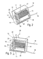
- zwei perspektivische Detailansichten des Versorgungs- und Abnehmerbauteils im gekoppelten Zustand,
- Figuren 4 und 5
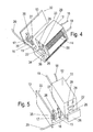
- zwei perspektivische Detailansichten des Versorgungs- und Abnehmerbauteils im entkoppelten Zustand,
- Figur 6
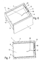
- eine perspektivische Ansicht des Möbels aus
Figur 1 mit in seiner Schließstellung positionierten beweglichem Möbelteil - Figur 7
- eine Draufsicht auf das Möbel aus
Figur 6 und - Figur 8
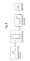
- ein Blockschaltbild zur Darstellung der Funktionsweise eines bistabilen Relais.
- In den nachfolgenden Figurenbezeichnungen beziehen sich Begriffe wie oben, unten, links, rechts, vorne; hinten usw. ausschließlich auf die jeweiligen in den Figuren gewählten beispielhaften Darstellungen und Positionen der Vorrichtung und anderer Gegenstände. Diese Begriffe sind nicht einschränkend zu verstehen, d. h. in verschiedenen Arbeitsstellungen oder durch spiegelsymmetrische Auslegung oder dergleichen können sich diese Bezüge ändern.
- Die
Figuren 1 ,6 und 7 zeigen ein Möbel 1 mit einem Möbelkorpus 31 und einem relativ zu dem Möbelkorpus 31 beweglichen Möbelteil 5 in verschiedenen Arbeitsstellungen, wobei das bewegliche Möbelteil 5 in der hier gezeigten besonderen Ausführungsform als ausziehbarer und einschiebbarer Schubkasten mit einer Frontblende 9, einem Boden 10 und zwei Schubkastenseitenwänden 6, 7 ausgebildet ist. - An den Möbelkorpus 31 ist an einer Rückwand 4, welche zwischen zwei Seitenwänden 2 und 3 angeordnet ist, ein Versorgungsbauteil 33 festgelegt, das zusammen mit einem Abnehmerbauteil 32, welches an einer Rückwand 8 eines als Schubkasten ausgebildeten beweglichen Möbelteils 5 befestigt ist, die Vorrichtung zur Übergabe elektrischer Energie 11 ausbildet. Mit dem Abnehmerbauteil 32 ist ein Elektrokabel 20 verbunden, dass die elektrische Energie von dem Abnehmerbauteil 32 an die in dem beweglichen Möbelteil 5 angeordneten elektrisch betriebenen Geräte weiterleitet.
- Das Versorgungsbauteil 33 und das Abnehmerbauteil 32 sind in den
Figuren 2 bis 5 detailliert dargestellt. - Das Versorgungsbauteil 33 weist ein Gehäuse 12 auf, das in der hier gezeigten Ausführungsvariante etwa in Form eines G ausgebildet ist, mit einer von vier Seiten umschlossenen Kammer 37 und einer senkrecht aus einer verlängerten Seitenwand der Kammer 37 hervorstehenden Wandung 38. An der der Wandung 38 gegenüberliegenden Seitenwand der Kammer sind bevorzugt zwei Kontaktbauteile 23, 24 angeordnet, welche an ein Elektrokabel 18 angeschlossen sind und über dieses Elektrokabel 18 mit elektrischer Energie versorgt werden. Zum Anschluss der beiden Kontaktbauteile 23, 24 an das Elektrokabel 18 ist dieses mit zwei Litzen 21 versehen. Die Kontaktbauteile 23, 24 des Versorgungsbauteils 33 sind dabei bevorzugt in Aussparungen 28, 29 an der Innenseite der Kammer 37 angeordnet.
- In der Kammer 37 des Gehäuses 12 ist eine Spule 14 eines Elektromagneten mit einem magnetisierbaren Spulenkern 22 angeordnet, der durch eine Gehäuseöffnung in einer Seitenwand der Kammer 37 hindurchragt. Die Gehäuseöffnung für den Spulenkern 22 ist dabei auf der gleichen Kammerseite angeordnet wie die Kontaktbauteile 23, 24 des Versorgungsbauteils 33.
- Das Abnehmerbauteil 32 weist im Wesentlichen ein bevorzugt flächiges Befestigungselement 13 auf, mit dem das Abnehmerbauteil 32 an dem beweglichen Möbelteil 5 befestigt ist. Aus der dem beweglichen Möbelteil 5 abgewandten Seite des Befestigungselements 13 steht senkrecht ein Schenkel 15 hervor. Die Kontaktbauteile 16, 17 des Abnehmerbauteils 32 sind bevorzugt federnd an dem Schenkel 15 angeordnet.
- An den beiden Kontaktelementen 16, 17 ist bevorzugt ein flächig ausgebildetes Element 35 angeordnet, der in der Schließposition des beweglichen Möbelteils 5 dem Spulenkern 22 der Spule 14 gegenüber liegt und bei Aktivierung der Spule 14 von diesem angezogen wird.
- Die oberen Enden der Kontaktelemente 16, 17 des Abnehmerbauteil 32 sind als Kontaktköpfe 26, 27 ausgebildet. Die Kontaktköpfe 26, 27 sind dabei bevorzugt U-förmig gebogen, so dass diese mit der geschlossenen Seite des U in die Aussparungen 28, 29 des Gehäuses 12 des Versorgungsbauteils 33 eintauchen, sobald das an den Kontaktelementen 16, 17 des Abnehmerbauteils 32 angeordnete flächige magnetisierbare Element 35 durch den Spulenkern 22, magnetisiert durch Spule 14, angezogen wird.
- Die Kontaktbauteile 23, 24 sind so angeordnet, dass sie, wenn das bewegliche Möbelteil 5 in einer Schließstellung positioniert ist, mit den Kontaktbauteilen 16, 17 des an dem beweglichen Möbelteil 5 angeordneten Abnehmerbauteils 32 eine elektrische Verbindung herstellen können.
Das Versorgungsbauteil 33 ist des Weiteren mit einer elektrischen Steuerschaltung 36 und einer an diese gekoppelten Positionserkennungseinrichtung 25, 34 ausgebildet, wobei die Steuerschaltung 36 ebenso mit den aus Spule 14 und Spulenkern 22 bestehenden Elektromagneten gekoppelt ist. - Die Positionserkennungseinrichtung 25, 34 ist bevorzugt als lichtschrankenähnliche Einrichtung ausgebildet, wobei in der Seite der Gehäusekammer 37, in dem auch die Ausnehmung vorgesehen ist, durch den der Spulenkern 22 der Spule 14 hindurch ragt, eine Senderdiode 25 integriert ist, der gegenüber an der Gehäusewand 38 eine Empfängerdiode 34 angeordnet ist.
- Zur Unterbrechung dieser Lichtschranke ist an dem Abnehmerbauteil 32 ein Schenkel 15 vorgesehen, welcher beim Einfahren des beweglichen Möbelteils 5 in den Möbelkorpus 31 zwischen die Senderdiode 25 und die Empfängerdiode 34 in eine Gehäusefreimachung des Gehäuses 12 eintaucht und dabei den Lichtstrahl der lichtschrankenähnlichen Einrichtung unterbricht. Als Gehäusefreimachung ist hier die Lücke zwischen der Wandung 38 des Gehäuses und der Kammer 37 zu verstehen. Die als lichtschrankenähnliche Einrichtung ausgebildete Positionserkennungseinrichtung ist mit der Steuerschaltung 36 so gekoppelt, dass die Steuerschaltung 36 diese Unterbrechung erkennt und daraufhin eine elektrische Versorgung der Spule 14 ansteuert.
- Vorzugsweise kann diese Spannungsversorgung dabei mit einer geringen zeitlichen Verzögerung erfolgen, damit beispielsweise eine Selbsteinzugsvorrichtung eines Schubkastensystems die erforderliche Endlage sicher ungebremst erreichen kann, bevor das Versorgungsbauteil 33 mit dem Abnehmerbauteil 32 elektrisch in Kontakt tritt.
- Durch die elektromagnetische Wirkung der Spule 14 wird der Spulenkern 22 magnetisiert und zieht das magnetische Element 35 an. Durch die Verbindung der Magneteinrichtung 22, 35 werden die Kontaktsätze 16, 17 des Abnehmerbauteils 32 in Richtung der Kontaktsätze 23, 24 des Versorgungsbauteils 33 gezogen und kontaktieren die Kontaktsätze 23, 24 des Versorgungsbauteils 33. Dadurch ist eine Energieversorgung des beweglichen Möbelteils 5 über die an dem Möbelkorpus 31 in den Versorgungsbauteil 33 angeordneten Kontaktsätze 23, 24, welche über ein Elektrokabel 18 mit elektrischer Energie versorgt werden, ermöglicht. Die Spannungsversorgung der Spule 14 und der Steuerschaltung 36 erfolgt bevorzugt über ein separates Elektrokabel 19.
- Nach dem Abschalten der Versorgungsspannung der Spule 14 federn die Kontaktsätze 16, 17 wieder zurück in ihre Ausgangsstellung. Dabei wird die elektrische Verbindung zwischen den Kontaktsätzen 16, 17, 23, 24 wieder unterbrochen.
- In einer besonderen Ausführungsvariante sind die Kontaktsätze 16, 17, 23, 24 mechanisch ineinander verrastbar ausgeführt. Dadurch kann nach dem Anziehen der Magneteinrichtung 22, 35 die Spule 14 stromlos geschaltet werden, ohne die elektrische Verbindung zwischen den Kontaktsätzen 16, 17, 23, 24 zu unterbrechen. Die mechanische Rastung wird wieder aufgehoben, indem beispielsweise das bewegliche Möbelteil 5 in "auf" -Richtung betätigt wird. Alternativ könnte zur mechanischen Entrastung ein kurzer Hub in "zu" -Richtung erfolgen. In einer weiteren Alternative kann die Verrastung durch eine erneute Aktivierung der Spule 14 rückgängig gemacht werden.
- Wie in
Figur 8 dargestellt, ist dieses in der Art eines bistabilen Relais möglich. Dabei erfasst die Auslöseeinheit die Endlage des eingeschobenen Schubkastens. Die positive Signalflankenerkennung triggert die Signal-Zeitverzögerung an, die am Ausgang nach der voreingestellten Zeit einen Wischimpuls bereitstellt. -
- 1
- Möbel
- 2
- Seitenwand
- 3
- Seitenwand
- 4
- Rückwand
- 5
- bewegliches Möbelteil
- 6
- Schubkastenseitenwand
- 7
- Schubkastenseitenwand
- 8
- Rückwand
- 9
- Frontblende
- 10
- Boden
- 11
- Vorrichtung zur Übertragung elektrischer Energie
- 12
- Gehäuse
- 13
- Befestigungselement
- 14
- Spule
- 15
- Schenkel
- 16
- Kontaktbauteil
- 17
- Kontaktbauteil
- 18
- Elektrokabel
- 19
- Elektrokabel
- 20
- Elektrokabel
- 21
- Gabelung
- 22
- Spulenkern
- 23
- Kontaktbauteil
- 24
- Kontaktbauteil
- 25
- Senderdiode
- 26
- Kontaktkopf
- 27
- Kontaktkopf
- 28
- Aussparung
- 29
- Aussparung
- 31
- Möbelkorpus
- 32
- Abnehmerbauteil
- 33
- Versorgungsbauteil
- 34
- Empfängerdiode
- 35
- Metallisches Flächenelement
- 36
- Steuerschaltung
- 37
- Kammer
- 38
- Wandung
Claims (12)
- Vorrichtung zur Übertragung elektrischer Energie zwischen einem an einem Möbelkorpus (31) angeordneten Versorgungsbauteil (33) und einem an einem relativ zum Möbelkorpus (31) beweglichen Möbelteil (5), insbesondere einem relativ zum Möbelkorpus (31) verschiebbaren Schubkasten, angeordneten Abnehmerbauteil (32), wobei das Versorgungsbauteil (33) einen elektromechanischen Kontaktsatz (23, 24) aufweist, der zur Übertragung elektrischer Energie mit einem elektromechanischen Kontaktsatz (16, 17) des Abnehmerbauteils (32) in einer Schließstellung des beweglichen Möbelteils koppelbar ist, dadurch gekennzeichnet, dassa. das Versorgungsbauteil (33) eine mit einer elektrischen Steuerschaltung (36) gekoppelte Positionserkennungseinrichtung (25, 34) und einen von der elektrischen Steuerschaltung (36) steuerbaren Elektromagneten (14, 22) undb. das Abnehmerbauteil (32) ein magnetisierbares Element (35) aufweist,
wobei sich der Elektromagnet (14, 30) und das magnetisierbare Element (35) in einer Schließstellung des beweglichen Möbelteils (5) gegenüberstehen, so dass die Kontaktsätze (16, 17, 23, 24) durch eine Aktivierung des Elektromagneten (14, 22) durch die Steuerschaltung (36) miteinander in Kontakt bringbar sind. - Vorrichtung nach Anspruch 1, dadurch gekennzeichnet, dass die Positionserkennungseinrichtung (25, 34) als lichtschrankenähnliche Einrichtung ausgebildet ist und das Abnehmerbauteil (32) in der Schließstellung des beweglichen Möbelteils (5) so positioniert ist, dass ein von der lichtschrankenähnlichen Einrichtung definierter Lichtweg unterbrochen ist.
- Vorrichtung nach Anspruch 2, dadurch gekennzeichnet, dass an dem Abnehmerbauteil (32) ein Schenkel (15) zur Unterbrechung des von der lichtschrankenähnlichen Einrichtung definierten Lichtweges vorgesehen ist.
- Vorrichtung nach einem der vorstehenden Ansprüche, dadurch gekennzeichnet, dass das magnetisierbare Element (35) an dem Kontaktsatz (16, 17) des Abnehmerbauteils (32) angeordnet ist und der Kontaktsatz (16, 17) an dem Abnehmerbauteil (32) in Richtung des Kontaktsatzes (23, 24) des Versorgungsbauteils (33) hin bewegbar angeordnet ist.
- Vorrichtung nach einem der vorstehenden Ansprüche, dadurch gekennzeichnet, dass das Versorgungsbauteil (33) ein Gehäuse (12) aufweist, das am Möbelkorpus (31) angeordnet ist und das Abnehmerbauteil (32) ein Befestigungselement (13) aufweist, das am beweglichen Möbelteil (5) angeordnet ist.
- Vorrichtung nach Anspruch 5, dadurch gekennzeichnet, dass an dem Gehäuse (12) des Versorgungsbauteils (33) Aussparungen (28, 29) vorgesehen sind, wobei der Kontaktsatz (23, 24) des Versorgungsbauteils (33) auf einer Gehäuseinnenseite der Aussparungen (28, 29) angeordnet ist und der Kontaktsatz (16, 17) des Abnehmerbauteils (32) Kontaktköpfe (26, 27) aufweist, die zur Koppelung mit dem Kontaktsatz (23, 24) des Versorgungsbauteils (33) in die Aussparungen (28, 29) eintauchbar sind.
- Vorrichtung nach einem der vorstehenden Ansprüche, dadurch gekennzeichnet, dass die Kontaktsätze (16, 17, 23, 24) miteinander verrastbar ausgebildet sind.
- Vorrichtung nach einem der vorstehenden Ansprüche, dadurch gekennzeichnet, dass die Kontaktsätze (16, 17) federformartige Verlängerungen aufweisen.
- Vorrichtung nach Anspruch 7 oder 8, dadurch gekennzeichnet, dass die Verrastung der Kontaktsätze (16, 17, 23, 24) durch Aktivieren des Elektromagneten (14, 22) aufhebbar ist.
- Vorrichtung nach Anspruch 9, dadurch gekennzeichnet, dass die Verrastung der Kontaktsätze (16, 17, 23, 24) durch Aktivieren des Elektromagneten (14, 22) nach Art eines bistabilen Relais aufhebbar ist.
- Vorrichtung nach einem der vorstehenden Ansprüche, dadurch gekennzeichnet, dass die elektrische Steuerschaltung (36) eine Verzögerungseinheit aufweist, die so geschaltet ist, dass eine Energieversorgung des Elektromagneten (14, 22) zeitlich verzögert auf ein Signal der Positionserkennungseinrichtung (25, 34) erfolgt.
- Möbel mit einem Möbelkorpus (31) und mit wenigstens einem oder mehreren relativ zum Möbelkorpus (31) beweglichen Möbelteil/Möbelteilen (5), insbesondere mit einem oder mehreren relativ zum Möbelkorpus verschieblichen Schubkasten/Schubkästen, gekennzeichnet durch eine Vorrichtung zur Übertragung elektrischer Energie (11) nach einem der vorstehenden Ansprüche.
Applications Claiming Priority (2)
| Application Number | Priority Date | Filing Date | Title |
|---|---|---|---|
| DE202009004882U DE202009004882U1 (de) | 2009-06-03 | 2009-06-03 | Vorrichtung zur Übertragung elektrischer Energie |
| PCT/EP2010/056840 WO2010139551A2 (de) | 2009-06-03 | 2010-05-18 | Vorrichtung zur übertragung elektrischer energie |
Publications (2)
| Publication Number | Publication Date |
|---|---|
| EP2437632A2 EP2437632A2 (de) | 2012-04-11 |
| EP2437632B1 true EP2437632B1 (de) | 2015-02-25 |
Family
ID=42993838
Family Applications (1)
| Application Number | Title | Priority Date | Filing Date |
|---|---|---|---|
| EP10782998.8A Not-in-force EP2437632B1 (de) | 2009-06-03 | 2010-05-18 | Vorrichtung zur übertragung elektrischer energie |
Country Status (8)
| Country | Link |
|---|---|
| EP (1) | EP2437632B1 (de) |
| JP (1) | JP2012528615A (de) |
| KR (1) | KR20120037443A (de) |
| CN (1) | CN102804516B (de) |
| AU (1) | AU2010255902A1 (de) |
| DE (1) | DE202009004882U1 (de) |
| RU (1) | RU2011152804A (de) |
| WO (1) | WO2010139551A2 (de) |
Families Citing this family (4)
| Publication number | Priority date | Publication date | Assignee | Title |
|---|---|---|---|---|
| ITCH20120004A1 (it) * | 2012-03-05 | 2013-09-06 | Costantini Mauro Fal Co Falegnameria Costantini D | Porta-lampada: porta in legno con integrato impianto illuminante |
| DE102013109304A1 (de) * | 2013-08-28 | 2015-03-05 | Paul Hettich Gmbh & Co. Kg | Beschlag eines Möbels oder Haushaltsgerätes und Möbel oder Haushaltsgerät |
| CN105795717A (zh) * | 2016-03-31 | 2016-07-27 | 联想(北京)有限公司 | 一种桌子 |
| AT525028B1 (de) * | 2021-04-30 | 2023-08-15 | Blum Gmbh Julius | Energieversorgungsvorrichtung |
Citations (1)
| Publication number | Priority date | Publication date | Assignee | Title |
|---|---|---|---|---|
| EP1260158A2 (de) * | 2001-05-17 | 2002-11-27 | Julius Blum Gesellschaft m.b.H. | Möbelschublade |
Family Cites Families (15)
| Publication number | Priority date | Publication date | Assignee | Title |
|---|---|---|---|---|
| DE745899C (de) * | 1943-03-04 | 1944-05-24 | Tobis Tonbild Syndikat G M B H | Stromzufuehrung fuer Beleuchtungsvorrichtungen an Notenpulten |
| DE3303727A1 (de) * | 1983-02-04 | 1984-08-09 | Gluma GmbH Elektrotechnische Erzeugnisse, 7887 Laufenburg | Einrichtung zur uebertragung elektrischer energie |
| JPS6116880U (ja) * | 1984-07-05 | 1986-01-31 | 日本電気株式会社 | ケ−ブル接続器におけるプラグ着脱検出装置 |
| JPS62200261U (de) * | 1986-06-10 | 1987-12-19 | ||
| JPH10225000A (ja) * | 1997-01-31 | 1998-08-21 | Sanyo Electric Co Ltd | コードレス電話機の充電装置及び子機 |
| CN2337616Y (zh) * | 1998-06-16 | 1999-09-08 | 罗建新 | 计生用品无人售货机 |
| CN2592518Y (zh) * | 2002-09-03 | 2003-12-17 | 北京东华原医疗设备有限责任公司 | 小型液体包装机包装量控制装置 |
| JP4515126B2 (ja) * | 2004-03-26 | 2010-07-28 | 大日本印刷株式会社 | 引出付収納ケース |
| DE202005006945U1 (de) * | 2005-04-28 | 2006-05-04 | Grass Gmbh | Öffnungs- und Schließsystem, insbesondere für Möbelteile |
| DE202006003065U1 (de) * | 2006-01-11 | 2006-05-11 | Pöllet, Wilfried | Energieversorgungs-Einrichtung für einen beweglich montierten Verbraucher |
| DE202006006189U1 (de) * | 2006-04-18 | 2007-08-30 | Paul Hettich Gmbh & Co. Kg | Antriebseinrichtung für bewegbare Möbelteile |
| DE202006007151U1 (de) * | 2006-05-04 | 2007-09-20 | Hettich Strothmann Gmbh & Co. Kg | Möbel |
| JP4993946B2 (ja) * | 2006-05-15 | 2012-08-08 | 株式会社ニフコ | 引出装置 |
| DE202007016660U1 (de) * | 2007-12-03 | 2009-04-16 | Paul Hettich Gmbh & Co. Kg | Möbel mit einer Einrichtung zur drahtlosen Übertragung von Elektrischer Energie |
| DE202008000195U1 (de) * | 2008-01-05 | 2008-04-17 | Häcker Küchen GmbH & Co. KG | Küchenmöbel mit Schublade und Beleuchtung |
-
2009
- 2009-06-03 DE DE202009004882U patent/DE202009004882U1/de not_active Expired - Lifetime
-
2010
- 2010-05-18 RU RU2011152804/07A patent/RU2011152804A/ru not_active Application Discontinuation
- 2010-05-18 JP JP2012513536A patent/JP2012528615A/ja active Pending
- 2010-05-18 AU AU2010255902A patent/AU2010255902A1/en not_active Abandoned
- 2010-05-18 EP EP10782998.8A patent/EP2437632B1/de not_active Not-in-force
- 2010-05-18 KR KR1020127000077A patent/KR20120037443A/ko not_active Withdrawn
- 2010-05-18 WO PCT/EP2010/056840 patent/WO2010139551A2/de not_active Ceased
- 2010-05-18 CN CN201080024242.4A patent/CN102804516B/zh not_active Expired - Fee Related
Patent Citations (1)
| Publication number | Priority date | Publication date | Assignee | Title |
|---|---|---|---|---|
| EP1260158A2 (de) * | 2001-05-17 | 2002-11-27 | Julius Blum Gesellschaft m.b.H. | Möbelschublade |
Also Published As
| Publication number | Publication date |
|---|---|
| WO2010139551A3 (de) | 2012-01-26 |
| WO2010139551A2 (de) | 2010-12-09 |
| CN102804516B (zh) | 2015-02-25 |
| AU2010255902A1 (en) | 2011-12-15 |
| KR20120037443A (ko) | 2012-04-19 |
| DE202009004882U1 (de) | 2010-10-21 |
| CN102804516A (zh) | 2012-11-28 |
| JP2012528615A (ja) | 2012-11-15 |
| RU2011152804A (ru) | 2013-07-20 |
| EP2437632A2 (de) | 2012-04-11 |
Similar Documents
| Publication | Publication Date | Title |
|---|---|---|
| EP1778995B1 (de) | Elektromagnetische reibschlüssige schaltkupplung, verfahren zu ihrem betrieb und verwendung innerhalb eines antriebsstranges zur automatischen betätigung einer fahrzeugtür oder fahrzeugklappe | |
| EP3877639B1 (de) | Steckadapter zum andocken an ein magnetventil | |
| EP1378416A1 (de) | Elektrokontaktkupplung | |
| DE2730660A1 (de) | Elektrische kupplungsvorrichtung | |
| DE102009014584A1 (de) | Beweglicher Kontakthalter einer elektrischen Vorrichtung sowie Montageverfahren für einen beweglichen Kontakthalter | |
| EP0316691A1 (de) | Einrichtung zur Überwachung des Schliesszustands eines Verschlussorgans | |
| EP2957696B1 (de) | Feststellvorrichtung für einen flügel | |
| DE102016117782A1 (de) | Elektrischer Schalter | |
| EP2437632A2 (de) | Vorrichtung zur übertragung elektrischer energie | |
| EP2385205A2 (de) | Verriegelungs- bzw. Feststellvorrichtung für eine Flügelanlage | |
| DE102008051183A1 (de) | Elektromechanisches Verbindungssystem | |
| DE102005013197A1 (de) | Magnetische Betätigungsvorrichtung | |
| WO2013071906A2 (de) | Vorrichtung zur verriegelung eines elektrosteckers für ein kraftfahrzeug | |
| EP3038496A1 (de) | Beschlag eines möbels oder haushaltsgerätes und möbel oder haushaltsgerät | |
| DE102010011204A1 (de) | Schaltschrank und Geräteträger für einen Schaltschrank | |
| DE69834859T2 (de) | Elektrischer Einheit mit Betätigungseinrichtung für einen Schutzschalter | |
| EP3460157B1 (de) | Feststellvorrichtung | |
| DE69215348T2 (de) | Schaltgeräte für elektromagnetische und manuelle Betätigung | |
| DE19738074C2 (de) | Notabschaltvorrichtung, insbesondere bei Elektro-Flurförderzeugen zum Trennen der Verbindung zwischen Motor oder dessen Steuereinheit und den Antriebsbatterien für diesen | |
| DE202018103643U1 (de) | Schienenführung, Möbelteil und Möbel | |
| DE2417236C3 (de) | Schalterantrieb mit einem Linearmotor | |
| EP2747287A1 (de) | Schaltungsanordnung zum Bremsen einer sich bewegenden Masse beim Abschalten eines elektromechanischen Schaltgeräts mit einer induktiven Last | |
| EP2636824A2 (de) | Feststellvorrichtung | |
| EP2587508A1 (de) | Leistungsschutzschalter | |
| DE102010013058B4 (de) | Überlastkupplung |
Legal Events
| Date | Code | Title | Description |
|---|---|---|---|
| PUAI | Public reference made under article 153(3) epc to a published international application that has entered the european phase |
Free format text: ORIGINAL CODE: 0009012 |
|
| 17P | Request for examination filed |
Effective date: 20111220 |
|
| AK | Designated contracting states |
Kind code of ref document: A2 Designated state(s): AL AT BE BG CH CY CZ DE DK EE ES FI FR GB GR HR HU IE IS IT LI LT LU LV MC MK MT NL NO PL PT RO SE SI SK SM TR |
|
| DAX | Request for extension of the european patent (deleted) | ||
| 17Q | First examination report despatched |
Effective date: 20130515 |
|
| GRAP | Despatch of communication of intention to grant a patent |
Free format text: ORIGINAL CODE: EPIDOSNIGR1 |
|
| INTG | Intention to grant announced |
Effective date: 20141017 |
|
| GRAS | Grant fee paid |
Free format text: ORIGINAL CODE: EPIDOSNIGR3 |
|
| GRAA | (expected) grant |
Free format text: ORIGINAL CODE: 0009210 |
|
| AK | Designated contracting states |
Kind code of ref document: B1 Designated state(s): AL AT BE BG CH CY CZ DE DK EE ES FI FR GB GR HR HU IE IS IT LI LT LU LV MC MK MT NL NO PL PT RO SE SI SK SM TR |
|
| REG | Reference to a national code |
Ref country code: GB Ref legal event code: FG4D Free format text: NOT ENGLISH |
|
| REG | Reference to a national code |
Ref country code: CH Ref legal event code: EP |
|
| REG | Reference to a national code |
Ref country code: IE Ref legal event code: FG4D Free format text: LANGUAGE OF EP DOCUMENT: GERMAN |
|
| REG | Reference to a national code |
Ref country code: DE Ref legal event code: R096 Ref document number: 502010008997 Country of ref document: DE Effective date: 20150409 |
|
| REG | Reference to a national code |
Ref country code: AT Ref legal event code: REF Ref document number: 711162 Country of ref document: AT Kind code of ref document: T Effective date: 20150415 |
|
| REG | Reference to a national code |
Ref country code: NL Ref legal event code: VDEP Effective date: 20150225 |
|
| REG | Reference to a national code |
Ref country code: LT Ref legal event code: MG4D |
|
| PG25 | Lapsed in a contracting state [announced via postgrant information from national office to epo] |
Ref country code: LT Free format text: LAPSE BECAUSE OF FAILURE TO SUBMIT A TRANSLATION OF THE DESCRIPTION OR TO PAY THE FEE WITHIN THE PRESCRIBED TIME-LIMIT Effective date: 20150225 Ref country code: NO Free format text: LAPSE BECAUSE OF FAILURE TO SUBMIT A TRANSLATION OF THE DESCRIPTION OR TO PAY THE FEE WITHIN THE PRESCRIBED TIME-LIMIT Effective date: 20150525 Ref country code: HR Free format text: LAPSE BECAUSE OF FAILURE TO SUBMIT A TRANSLATION OF THE DESCRIPTION OR TO PAY THE FEE WITHIN THE PRESCRIBED TIME-LIMIT Effective date: 20150225 Ref country code: ES Free format text: LAPSE BECAUSE OF FAILURE TO SUBMIT A TRANSLATION OF THE DESCRIPTION OR TO PAY THE FEE WITHIN THE PRESCRIBED TIME-LIMIT Effective date: 20150225 Ref country code: FI Free format text: LAPSE BECAUSE OF FAILURE TO SUBMIT A TRANSLATION OF THE DESCRIPTION OR TO PAY THE FEE WITHIN THE PRESCRIBED TIME-LIMIT Effective date: 20150225 Ref country code: SE Free format text: LAPSE BECAUSE OF FAILURE TO SUBMIT A TRANSLATION OF THE DESCRIPTION OR TO PAY THE FEE WITHIN THE PRESCRIBED TIME-LIMIT Effective date: 20150225 |
|
| PG25 | Lapsed in a contracting state [announced via postgrant information from national office to epo] |
Ref country code: GR Free format text: LAPSE BECAUSE OF FAILURE TO SUBMIT A TRANSLATION OF THE DESCRIPTION OR TO PAY THE FEE WITHIN THE PRESCRIBED TIME-LIMIT Effective date: 20150526 Ref country code: LV Free format text: LAPSE BECAUSE OF FAILURE TO SUBMIT A TRANSLATION OF THE DESCRIPTION OR TO PAY THE FEE WITHIN THE PRESCRIBED TIME-LIMIT Effective date: 20150225 Ref country code: IS Free format text: LAPSE BECAUSE OF FAILURE TO SUBMIT A TRANSLATION OF THE DESCRIPTION OR TO PAY THE FEE WITHIN THE PRESCRIBED TIME-LIMIT Effective date: 20150625 |
|
| PG25 | Lapsed in a contracting state [announced via postgrant information from national office to epo] |
Ref country code: NL Free format text: LAPSE BECAUSE OF FAILURE TO SUBMIT A TRANSLATION OF THE DESCRIPTION OR TO PAY THE FEE WITHIN THE PRESCRIBED TIME-LIMIT Effective date: 20150225 |
|
| PG25 | Lapsed in a contracting state [announced via postgrant information from national office to epo] |
Ref country code: DK Free format text: LAPSE BECAUSE OF FAILURE TO SUBMIT A TRANSLATION OF THE DESCRIPTION OR TO PAY THE FEE WITHIN THE PRESCRIBED TIME-LIMIT Effective date: 20150225 Ref country code: EE Free format text: LAPSE BECAUSE OF FAILURE TO SUBMIT A TRANSLATION OF THE DESCRIPTION OR TO PAY THE FEE WITHIN THE PRESCRIBED TIME-LIMIT Effective date: 20150225 Ref country code: SK Free format text: LAPSE BECAUSE OF FAILURE TO SUBMIT A TRANSLATION OF THE DESCRIPTION OR TO PAY THE FEE WITHIN THE PRESCRIBED TIME-LIMIT Effective date: 20150225 Ref country code: RO Free format text: LAPSE BECAUSE OF FAILURE TO SUBMIT A TRANSLATION OF THE DESCRIPTION OR TO PAY THE FEE WITHIN THE PRESCRIBED TIME-LIMIT Effective date: 20150225 Ref country code: CZ Free format text: LAPSE BECAUSE OF FAILURE TO SUBMIT A TRANSLATION OF THE DESCRIPTION OR TO PAY THE FEE WITHIN THE PRESCRIBED TIME-LIMIT Effective date: 20150225 |
|
| REG | Reference to a national code |
Ref country code: DE Ref legal event code: R097 Ref document number: 502010008997 Country of ref document: DE |
|
| PG25 | Lapsed in a contracting state [announced via postgrant information from national office to epo] |
Ref country code: PL Free format text: LAPSE BECAUSE OF FAILURE TO SUBMIT A TRANSLATION OF THE DESCRIPTION OR TO PAY THE FEE WITHIN THE PRESCRIBED TIME-LIMIT Effective date: 20150225 |
|
| PG25 | Lapsed in a contracting state [announced via postgrant information from national office to epo] |
Ref country code: IT Free format text: LAPSE BECAUSE OF FAILURE TO SUBMIT A TRANSLATION OF THE DESCRIPTION OR TO PAY THE FEE WITHIN THE PRESCRIBED TIME-LIMIT Effective date: 20150225 |
|
| REG | Reference to a national code |
Ref country code: CH Ref legal event code: PL |
|
| PLBE | No opposition filed within time limit |
Free format text: ORIGINAL CODE: 0009261 |
|
| STAA | Information on the status of an ep patent application or granted ep patent |
Free format text: STATUS: NO OPPOSITION FILED WITHIN TIME LIMIT |
|
| GBPC | Gb: european patent ceased through non-payment of renewal fee |
Effective date: 20150525 |
|
| PG25 | Lapsed in a contracting state [announced via postgrant information from national office to epo] |
Ref country code: CH Free format text: LAPSE BECAUSE OF NON-PAYMENT OF DUE FEES Effective date: 20150531 Ref country code: LU Free format text: LAPSE BECAUSE OF FAILURE TO SUBMIT A TRANSLATION OF THE DESCRIPTION OR TO PAY THE FEE WITHIN THE PRESCRIBED TIME-LIMIT Effective date: 20150518 Ref country code: MC Free format text: LAPSE BECAUSE OF FAILURE TO SUBMIT A TRANSLATION OF THE DESCRIPTION OR TO PAY THE FEE WITHIN THE PRESCRIBED TIME-LIMIT Effective date: 20150225 Ref country code: LI Free format text: LAPSE BECAUSE OF NON-PAYMENT OF DUE FEES Effective date: 20150531 |
|
| 26N | No opposition filed |
Effective date: 20151126 |
|
| REG | Reference to a national code |
Ref country code: IE Ref legal event code: MM4A |
|
| REG | Reference to a national code |
Ref country code: FR Ref legal event code: ST Effective date: 20160129 |
|
| PG25 | Lapsed in a contracting state [announced via postgrant information from national office to epo] |
Ref country code: SI Free format text: LAPSE BECAUSE OF FAILURE TO SUBMIT A TRANSLATION OF THE DESCRIPTION OR TO PAY THE FEE WITHIN THE PRESCRIBED TIME-LIMIT Effective date: 20150225 |
|
| PG25 | Lapsed in a contracting state [announced via postgrant information from national office to epo] |
Ref country code: IE Free format text: LAPSE BECAUSE OF NON-PAYMENT OF DUE FEES Effective date: 20150518 Ref country code: GB Free format text: LAPSE BECAUSE OF NON-PAYMENT OF DUE FEES Effective date: 20150525 |
|
| PG25 | Lapsed in a contracting state [announced via postgrant information from national office to epo] |
Ref country code: FR Free format text: LAPSE BECAUSE OF NON-PAYMENT OF DUE FEES Effective date: 20150601 |
|
| PG25 | Lapsed in a contracting state [announced via postgrant information from national office to epo] |
Ref country code: MT Free format text: LAPSE BECAUSE OF FAILURE TO SUBMIT A TRANSLATION OF THE DESCRIPTION OR TO PAY THE FEE WITHIN THE PRESCRIBED TIME-LIMIT Effective date: 20150225 |
|
| PG25 | Lapsed in a contracting state [announced via postgrant information from national office to epo] |
Ref country code: HU Free format text: LAPSE BECAUSE OF FAILURE TO SUBMIT A TRANSLATION OF THE DESCRIPTION OR TO PAY THE FEE WITHIN THE PRESCRIBED TIME-LIMIT; INVALID AB INITIO Effective date: 20100518 Ref country code: SM Free format text: LAPSE BECAUSE OF FAILURE TO SUBMIT A TRANSLATION OF THE DESCRIPTION OR TO PAY THE FEE WITHIN THE PRESCRIBED TIME-LIMIT Effective date: 20150225 Ref country code: BG Free format text: LAPSE BECAUSE OF FAILURE TO SUBMIT A TRANSLATION OF THE DESCRIPTION OR TO PAY THE FEE WITHIN THE PRESCRIBED TIME-LIMIT Effective date: 20150225 |
|
| PG25 | Lapsed in a contracting state [announced via postgrant information from national office to epo] |
Ref country code: CY Free format text: LAPSE BECAUSE OF FAILURE TO SUBMIT A TRANSLATION OF THE DESCRIPTION OR TO PAY THE FEE WITHIN THE PRESCRIBED TIME-LIMIT Effective date: 20150225 |
|
| PG25 | Lapsed in a contracting state [announced via postgrant information from national office to epo] |
Ref country code: BE Free format text: LAPSE BECAUSE OF NON-PAYMENT OF DUE FEES Effective date: 20150531 |
|
| PG25 | Lapsed in a contracting state [announced via postgrant information from national office to epo] |
Ref country code: TR Free format text: LAPSE BECAUSE OF FAILURE TO SUBMIT A TRANSLATION OF THE DESCRIPTION OR TO PAY THE FEE WITHIN THE PRESCRIBED TIME-LIMIT Effective date: 20150225 |
|
| PG25 | Lapsed in a contracting state [announced via postgrant information from national office to epo] |
Ref country code: MK Free format text: LAPSE BECAUSE OF FAILURE TO SUBMIT A TRANSLATION OF THE DESCRIPTION OR TO PAY THE FEE WITHIN THE PRESCRIBED TIME-LIMIT Effective date: 20150225 Ref country code: PT Free format text: LAPSE BECAUSE OF FAILURE TO SUBMIT A TRANSLATION OF THE DESCRIPTION OR TO PAY THE FEE WITHIN THE PRESCRIBED TIME-LIMIT Effective date: 20150225 |
|
| PG25 | Lapsed in a contracting state [announced via postgrant information from national office to epo] |
Ref country code: AL Free format text: LAPSE BECAUSE OF FAILURE TO SUBMIT A TRANSLATION OF THE DESCRIPTION OR TO PAY THE FEE WITHIN THE PRESCRIBED TIME-LIMIT Effective date: 20150225 |
|
| PGFP | Annual fee paid to national office [announced via postgrant information from national office to epo] |
Ref country code: DE Payment date: 20220519 Year of fee payment: 13 |
|
| PGFP | Annual fee paid to national office [announced via postgrant information from national office to epo] |
Ref country code: AT Payment date: 20220517 Year of fee payment: 13 |
|
| P01 | Opt-out of the competence of the unified patent court (upc) registered |
Effective date: 20230404 |
|
| REG | Reference to a national code |
Ref country code: DE Ref legal event code: R119 Ref document number: 502010008997 Country of ref document: DE |
|
| REG | Reference to a national code |
Ref country code: AT Ref legal event code: MM01 Ref document number: 711162 Country of ref document: AT Kind code of ref document: T Effective date: 20230518 |
|
| PG25 | Lapsed in a contracting state [announced via postgrant information from national office to epo] |
Ref country code: AT Free format text: LAPSE BECAUSE OF NON-PAYMENT OF DUE FEES Effective date: 20230518 |
|
| PG25 | Lapsed in a contracting state [announced via postgrant information from national office to epo] |
Ref country code: DE Free format text: LAPSE BECAUSE OF NON-PAYMENT OF DUE FEES Effective date: 20231201 |