EP2438294B1 - Procédé et dispositif d'installation d'une centrale marémotrice - Google Patents
Procédé et dispositif d'installation d'une centrale marémotrice Download PDFInfo
- Publication number
- EP2438294B1 EP2438294B1 EP11734006A EP11734006A EP2438294B1 EP 2438294 B1 EP2438294 B1 EP 2438294B1 EP 11734006 A EP11734006 A EP 11734006A EP 11734006 A EP11734006 A EP 11734006A EP 2438294 B1 EP2438294 B1 EP 2438294B1
- Authority
- EP
- European Patent Office
- Prior art keywords
- floating device
- coupling
- power plant
- tidal power
- nacelle
- Prior art date
- Legal status (The legal status is an assumption and is not a legal conclusion. Google has not performed a legal analysis and makes no representation as to the accuracy of the status listed.)
- Not-in-force
Links
Images



Classifications
-
- F—MECHANICAL ENGINEERING; LIGHTING; HEATING; WEAPONS; BLASTING
- F03—MACHINES OR ENGINES FOR LIQUIDS; WIND, SPRING, OR WEIGHT MOTORS; PRODUCING MECHANICAL POWER OR A REACTIVE PROPULSIVE THRUST, NOT OTHERWISE PROVIDED FOR
- F03B—MACHINES OR ENGINES FOR LIQUIDS
- F03B13/00—Adaptations of machines or engines for special use; Combinations of machines or engines with driving or driven apparatus; Power stations or aggregates
- F03B13/12—Adaptations of machines or engines for special use; Combinations of machines or engines with driving or driven apparatus; Power stations or aggregates characterised by using wave or tide energy
- F03B13/26—Adaptations of machines or engines for special use; Combinations of machines or engines with driving or driven apparatus; Power stations or aggregates characterised by using wave or tide energy using tide energy
- F03B13/264—Adaptations of machines or engines for special use; Combinations of machines or engines with driving or driven apparatus; Power stations or aggregates characterised by using wave or tide energy using tide energy using the horizontal flow of water resulting from tide movement
-
- E—FIXED CONSTRUCTIONS
- E02—HYDRAULIC ENGINEERING; FOUNDATIONS; SOIL SHIFTING
- E02B—HYDRAULIC ENGINEERING
- E02B9/00—Water-power plants; Layout, construction or equipment, methods of, or apparatus for, making same
- E02B9/08—Tide or wave power plants
-
- F—MECHANICAL ENGINEERING; LIGHTING; HEATING; WEAPONS; BLASTING
- F03—MACHINES OR ENGINES FOR LIQUIDS; WIND, SPRING, OR WEIGHT MOTORS; PRODUCING MECHANICAL POWER OR A REACTIVE PROPULSIVE THRUST, NOT OTHERWISE PROVIDED FOR
- F03B—MACHINES OR ENGINES FOR LIQUIDS
- F03B17/00—Other machines or engines
- F03B17/06—Other machines or engines using liquid flow with predominantly kinetic energy conversion, e.g. of swinging-flap type, "run-of-river", "ultra-low head"
- F03B17/061—Other machines or engines using liquid flow with predominantly kinetic energy conversion, e.g. of swinging-flap type, "run-of-river", "ultra-low head" with rotation axis substantially in flow direction
-
- E—FIXED CONSTRUCTIONS
- E02—HYDRAULIC ENGINEERING; FOUNDATIONS; SOIL SHIFTING
- E02B—HYDRAULIC ENGINEERING
- E02B17/00—Artificial islands mounted on piles or like supports, e.g. platforms on raisable legs or offshore constructions; Construction methods therefor
- E02B2017/0091—Offshore structures for wind turbines
-
- F—MECHANICAL ENGINEERING; LIGHTING; HEATING; WEAPONS; BLASTING
- F05—INDEXING SCHEMES RELATING TO ENGINES OR PUMPS IN VARIOUS SUBCLASSES OF CLASSES F01-F04
- F05B—INDEXING SCHEME RELATING TO WIND, SPRING, WEIGHT, INERTIA OR LIKE MOTORS, TO MACHINES OR ENGINES FOR LIQUIDS COVERED BY SUBCLASSES F03B, F03D AND F03G
- F05B2230/00—Manufacture
- F05B2230/60—Assembly methods
- F05B2230/61—Assembly methods using auxiliary equipment for lifting or holding
- F05B2230/6102—Assembly methods using auxiliary equipment for lifting or holding carried on a floating platform
-
- F—MECHANICAL ENGINEERING; LIGHTING; HEATING; WEAPONS; BLASTING
- F05—INDEXING SCHEMES RELATING TO ENGINES OR PUMPS IN VARIOUS SUBCLASSES OF CLASSES F01-F04
- F05B—INDEXING SCHEME RELATING TO WIND, SPRING, WEIGHT, INERTIA OR LIKE MOTORS, TO MACHINES OR ENGINES FOR LIQUIDS COVERED BY SUBCLASSES F03B, F03D AND F03G
- F05B2230/00—Manufacture
- F05B2230/70—Disassembly methods
-
- Y—GENERAL TAGGING OF NEW TECHNOLOGICAL DEVELOPMENTS; GENERAL TAGGING OF CROSS-SECTIONAL TECHNOLOGIES SPANNING OVER SEVERAL SECTIONS OF THE IPC; TECHNICAL SUBJECTS COVERED BY FORMER USPC CROSS-REFERENCE ART COLLECTIONS [XRACs] AND DIGESTS
- Y02—TECHNOLOGIES OR APPLICATIONS FOR MITIGATION OR ADAPTATION AGAINST CLIMATE CHANGE
- Y02E—REDUCTION OF GREENHOUSE GAS [GHG] EMISSIONS, RELATED TO ENERGY GENERATION, TRANSMISSION OR DISTRIBUTION
- Y02E10/00—Energy generation through renewable energy sources
- Y02E10/20—Hydro energy
-
- Y—GENERAL TAGGING OF NEW TECHNOLOGICAL DEVELOPMENTS; GENERAL TAGGING OF CROSS-SECTIONAL TECHNOLOGIES SPANNING OVER SEVERAL SECTIONS OF THE IPC; TECHNICAL SUBJECTS COVERED BY FORMER USPC CROSS-REFERENCE ART COLLECTIONS [XRACs] AND DIGESTS
- Y02—TECHNOLOGIES OR APPLICATIONS FOR MITIGATION OR ADAPTATION AGAINST CLIMATE CHANGE
- Y02E—REDUCTION OF GREENHOUSE GAS [GHG] EMISSIONS, RELATED TO ENERGY GENERATION, TRANSMISSION OR DISTRIBUTION
- Y02E10/00—Energy generation through renewable energy sources
- Y02E10/30—Energy from the sea, e.g. using wave energy or salinity gradient
-
- Y—GENERAL TAGGING OF NEW TECHNOLOGICAL DEVELOPMENTS; GENERAL TAGGING OF CROSS-SECTIONAL TECHNOLOGIES SPANNING OVER SEVERAL SECTIONS OF THE IPC; TECHNICAL SUBJECTS COVERED BY FORMER USPC CROSS-REFERENCE ART COLLECTIONS [XRACs] AND DIGESTS
- Y02—TECHNOLOGIES OR APPLICATIONS FOR MITIGATION OR ADAPTATION AGAINST CLIMATE CHANGE
- Y02P—CLIMATE CHANGE MITIGATION TECHNOLOGIES IN THE PRODUCTION OR PROCESSING OF GOODS
- Y02P70/00—Climate change mitigation technologies in the production process for final industrial or consumer products
- Y02P70/50—Manufacturing or production processes characterised by the final manufactured product
Definitions
- the invention relates to a method and a device for installing a tidal power plant on a buoyant or on the bottom of the water fundamend mandat support structure.
- a possible embodiment provides for a propeller-shaped water turbine, which is rotatably mounted on a nacelle.
- a propeller-shaped water turbine which is rotatably mounted on a nacelle.
- an electric generator driven by the water turbine.
- a foundation structure is built after a lake bed preparation. This may be, for example, a Monopile planting or the plant of a gravity foundation act. Above the actual foundation rises a support structure, typically a tower, to which the tidal power plant is placed in a second, subsequent installation step on an associated coupling device.
- a support structure typically a tower
- the tidal power plant is placed in a second, subsequent installation step on an associated coupling device.
- GB 2431628 discloses a device for installing a wave and tidal power plant.
- the invention has for its object to provide an only slightly influenced by the wave motion on the water surface installation device and an associated installation method.
- the installation device should be reusable and scalable. It should also require only a small ship-side lifting capacity and allow a quick and safe installation. Furthermore, the installation device for salvaging a tidal power plant should be suitable to perform a maintenance or plant replacement can.
- the object underlying the invention is solved by the features of the independent claims.
- the inventors have recognized that to install a tidal power plant on a submersible support structure, in particular a tower, the tidal power plant is to be provided with a removable floating device, wherein the installation unit resulting from this coupling has an adjustable buoyancy force.
- the vertical force caused by the buoyancy makes it possible to pull the installation unit against the coupling device by means of a cable pull arrangement originating from the support structure.
- the floating device is equipped with trim tanks to set a defined position of the installation unit as a function of the flow, buoyancy and Seilzug concept and by means of the Glasseilan extract the coupling device at the tidal power plant in a predetermined Horizontal position to lead the coupling counterpart on the support structure. It is further preferred to carry out the hauling of the traction cables of the traction cable arrangement via motor winches on the floating device. Accordingly, the installation unit draws by its own power to the support structure.
- the floating device is as simple as possible and thus formed fail-safe.
- the compressed air system for the operation of ballast tanks and the control necessary for this is preferably integrated into the floating device.
- the power supply and preferably a control signal line for carrying out control and regulation tasks or the transmission of sensory data can then be conducted by means of a cable connection to a supply ship up to above the water surface.
- the power cable of the tidal power plant is still connected to the system at the water surface.
- the supply line and the power cable take on substantially no load, so that the installation unit is decoupled with increasing depth of the force influences on the water surface, resulting in particular from the wave motion. Accordingly, the installation unit is largely influenced, in particular in the critical final phase of Turmannäh für by predictable force effects due to the flow and the adjustable buoyancy and traction forces.
- the installation unit of tidal power plant and swimming device with largely empty ballast tanks and thus a sufficient safety reserve for buoyancy by means of a ship's vehicle is towed.
- the traction cable arrangement is then established between the submersible support structure and the installation unit.
- a diving robot can be used, the tension cables attached to tower-side articulation points.
- a permanent attachment of the traction cables to the support structure wherein the free ends of the traction cables either permanently held by floats on the water surface or by remote-release floats are placed until the execution of the installation on the river bottom in the support structure.
- Further embodiments are conceivable, for example, to provide a retrieval system for the fixed ropes, which is created in the interior of the support structure.
- ballast tanks of the floating device are filled to reduce the buoyancy, which retains a positive value, so that the installation unit remains buoyant and can be pulled against the stabilizing force by the buoyancy force against the coupling device on the tower by means of Switzerlandseilanssen.
- the lowering of the installation unit is preferably carried out under flow. This leads to a leeward position of the water turbine during the approach to the support structure.
- trim tanks are provided, which are preferably designed as a closed system.
- the cable pull arrangement preferably comprises at least two traction ropes spaced apart from one another. It follows that the buoyancy of a rotational movement of the installation unit counteracts about the vertical axis, as this would lead to a twisting and a shortening of the Ceiseilanssen.
- several floating device-side articulation points are provided for the traction cable arrangement for stabilization on the floating body. Motor winches are preferably arranged on a part of these articulation points.
- the floating device After settling the installation unit and the execution of the coupling between the tidal power plant and the support structure, the floating device releases the tidal power plant again. To prepare for the associated load change load compensation tanks are filled at the floating device. In addition, it is preferred to wait for a change in the direction of flow in order to keep the floating device safely away from the water turbine by the flow pressure.
- the floating device is used to salvage a located in operating position on a support structure tidal power plant.
- a positive buoyancy floating device via the above-described Buchseilan extract to diving machine nacelle of the tidal power plant.
- Preference is again given to approaching under flow, so that the floating device at the rear, i. from the water turbine side facing away from, is approximated.
- the floating device is first coupled in the region of the gondola housing closure on the opposite side of the water turbine.
- an axial stop can also be provided on the floating device.
- the floating device is guided with a certain inclination to the nacelle, whereby a first contact results with the opposite side of the water turbine. Only in a subsequent step, the horizontal position is taken and fixed the other coupling points in the vicinity of the water turbine between the tidal power plant and the floating device. Then the load compensation tank of the floating device is emptied and a flow direction change is waited to by means of unwinding of the Switzerlandseilanssen the water turbine in a safe, sloping trajectory away from the support structure.
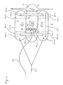
- FIG. 1 schematically simplified a swimming device 7 according to the invention is shown, to which a generic tidal power plant 1 is coupled.
- the coupling creates an installation unit 8 which serves to set down a tidal power station 1, which comprises a water turbine 2 and a machine nacelle 3, on a support structure which holds the tidal power station 1 in position during operation.
- the tidal power plant 1 is placed on a tower 6 during installation. This is a supported on a body of water base component, which is associated with the foundation, for example, a gravity foundation. Alternatively, the tower 6 may have a monopile foundation. Such is shown in the following embodiments.
- Conceivable are other embodiments, such as a buoyant, anchored on the water body support structure on which the tower 6 shown is placed.
- a connection between the coupling device 4 is made at the machine nacelle 3 of the tidal power station 1 and the coupling counterpart 5 on the tower 6 of the support structure during installation.
- the floating device 7 encloses the machine nacelle 3 in the form of a bow with a downwardly facing and axially extending opening for receiving the nacelle 3.
- the floating device 7 is preferably designed so that a direct contact of the machine nacelle 3 at several points to the wall of the floating device 7 exists.
- the coupling between the nacelle 3 and the Floating device 7 secured by a plurality of releasable coupling elements, which are not shown in detail.
- the installation unit 8 has a positive buoyancy, so that it can be used by means of a Buchseilan himself 9 against the action of the buoyancy force and acting on the installation unit 8 flow forces up to the coupling position.
- a Switzerlandseilan für 10.1, 10.2 which preferably has a paired arrangement of tension cables 10.1, 10.2. These each extend from a tower-side articulation point 11 at least indirectly to the floating-device-side articulation points 13.1, 13.2, 13.3 and 13.4.
- several pull cables 10.1, 10.2 stabilize the attraction of the installation unit 8 against the tower 6, since a twisting of the parallel spaced pull cables 10.1, 10.2 counteracts the buoyancy force on the installation unit 8.
- This effect can be enhanced by a spacing of the tower-side articulation points from the axis of the tower 6 by means of a cantilever 12.
- FIG. 2 shows a plan view of a principle sketch of the floating device used for the installation 7 for a tidal power station 1. Shown are the side tanks 22.1, 22.2 of the floating device 7, which are connected via cross members 17.1, 17.2. As a result, a gap is formed, which is open at the bottom and the recording of the machine nacelle 3 of the tidal power plant 1 is used. The adjoining the machine nacelle 3 and stored in this water turbine 2 projects axially beyond this gap and is due to their size outside the dimensions of the floating device. 7
- trim tanks 23.1, 23.2, 23.3, 23.4 which form a closed system in pairs.
- ballast water for adjusting a horizontal position of the installation unit 8 between the front trim tank 23.3 and the rear trim tank 23.4 is pumped by means of the connecting line 24 in the side tank 22.1.
- the trim tanks 23.1 and 23.2 cooperate in the further side tank 22.2.
- load compensation tanks 29.1, 29.2 are provided in each case, which compensate for the load change when weaning or picking up the tidal power station 1.
- a compressed air supply 26 is received in the floating device 7, which is operated by a measuring and control unit 25.
- This is preferably connected via a supply line 21 with a ship's vehicle in connection, the purpose serves to ensure the power supply for the floating device 7.
- at least a part of the necessary for the operation control and regulatory tasks is relocated to the water surface to make the floating device 7 as simple as possible and thus fail-safe.
- FIG. 2 outlined a security system 27, which can release additional buoyant body to secure the installation unit 8 in case of failure.
- the measuring and control unit 25 the compressed air supply 26 and the safety system 27 in the region of the cross member 17.1, 17.2 arranged.
- Particularly preferred is a closed embodiment of a cross member 17 according to the sketch FIG. 1 , which makes it possible to create foam-filled areas inside, which provide a safety reserve for the lift in the event of a fault of the compressed air supply 26.
- the installation unit 8 is towed in the floating state.
- a tow 20 is outlined to a in FIG. 2 not shown in detail watercraft is performed.
- the side tanks 22.1, 22.2 rudder 19 are arranged to improve the towing on the water surface. These are in FIG. 1 shown.
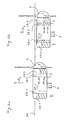
- FIG. 3a initially represents the operating condition suitable for towing.
- FIG. 3a initially represents the operating condition suitable for towing.
- a horizontally balanced floating position of the installation unit 8 can be seen, the axial weight distribution of the coupled tidal power station 1 being compensated by the selective adjustment of the fill level of the coupled trim tanks 23.1, 23.2.
- ballast tanks 28.1, 28.2 as well as the load compensation tank 29.1 are completely emptied, this results in a Buoyancy A 1 and a reliable position of the lifting point 35 and the center of gravity 36.
- the ballast tanks 28.1, 28.2 filled. These are preferably dimensioned such that when a complete filling is carried out, a positive buoyancy A 2 and a reliable position of the buoyancy point 35 relative to the center of gravity 36 continue to follow. Possibly, with a further immersion of the floating device 7 as well as the components of the water turbine 2, which are still located opposite the water surface, a change in the fill level in the trim tanks 23.1, 23.2 must be made.
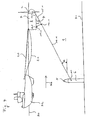
- FIG. 4 shows an already established connection by means of the Glasseilan Ich 9 between the tower 6 at the river bottom 31 and the tower-side articulation point 11 provided there and the floating device side articulation points 13.1, 13.2.
- To build this Buchseilan Ich 9 either not shown in detail dive robot is used or there is a permanent connection between the tower-side pivot point 11 and the attached pull rope 10.1.
- the traction cable 10.1 fastened to the tower 6 can be placed on the body of water 31 by means of a buoyancy unit which can be actuated remotely in the erection of the tower 6.
- a cable drum for the traction cable in the interior of the tower 6, via a radio link can be operated from a distance to handle a self-propelled rope end to initiate an installation to the surface.
- the traction cable 10.1 of the traction cable arrangement 9 runs from the tower-side articulation point 11 via a deflection roller 16.1 to the motor winch 14.1.
- This defines a first float side hinge point 13.1.
- only one pull cable 10.1 is shown.
- the installation is carried out at a certain flow, in this case there should be a flow direction 33, which orientates the installation unit 8 so that the water turbine 2 is leeward to the coupling device 4.
- a flow direction 33 which orientates the installation unit 8 so that the water turbine 2 is leeward to the coupling device 4.
- the flow condition suitable for installation is selected such that a predetermined haul rope angle a of the haul rope 10.1 relative to the horizontal is established.
- An angle range between 10 ° and 45 ° is preferred. Larger cable angles a arise at a lower flow or at an increase in the buoyancy of the installation unit 8.
- the connection to the tractor 32 via the tow 20 is maintained until the appropriate flow conditions for the installation are present.
- the positive buoyancy A 2 acting on installation can be adapted to the present flow in order to set the desired hoisting rope angle a.
- the length of the fixed cable 15.1 is selected to the deflection roller 16.1 such that preferably for the selected Glasseilwinkel a in the course of the entire Turmannäh für disappearing wrap angle of the pull cable 10.1 is present at the deflection roller 16.1.
- the installation unit 8 is then released by uncoupling the tow 20, wherein only the connection via the supply line 21 to the tractor remains, but which is without significant force on the installation unit 8.
- the power cable of the system is preferably mounted prior to immersion, for ease of illustration such is not shown in the figures.
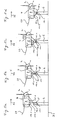
- the installation unit 8 as in FIG. 5a represented, above and lee mineral to the top of the tower 6.
- the motor winch 14.1 takes place in the FIGS. 5b and 5c illustrated successive approximation of the coupling device 4 of the tidal power plant 1 to the coupling counterpart 5 on the tower 6.
- the fixed cable 15.1 is preferably held on train, which causes a non-vanishing angle of the traction cable 10.1 on the guide roller 16.1.
- the length of the fixed cable 15.1 to the guide roller 16.1 is selected so that at a displacement of the guide roller 16.1 in the vicinity of the tower-side coupling point 11, the coupling device 4 of the tidal power plant 1 is directly above the coupling counterpart 5 on the tower 6.
- This presupposes a predetermined trim of the installation unit 8 and a lift A 2 which is matched to the present flow from the flow direction 33.
- These operating parameters are achievable by adjusting the water level in the trim tanks 23.1-23.4, and the ballast tanks 28.1-28.4.
- the deflection roller 16.1 led to the tower-side articulation point 11 and the fixed rope 15.1 transmitted in the sequence no tensile force on the float side coupling point 13.2, so that a pitching motion during insertion of the coupling device 4 in the coupling counterpart 5 is simplified.
- the necessary for safe operation operating parameters are detected by means of sensory systems on the floating device 7, which are not shown in detail.
- a flow sensor and a position sensor for trim control come into question.
- the end approach may be assisted by a video or sonar based monitoring system.
- the coupling device 4 and the coupling counterpart 5 are preferably provided with a funnel-shaped catching area and conical run-off surfaces, so that in a further catching-up of the pull cable 10 FIG. 5d shown situation of a connection between the coupling device 4 and the coupling counterpart 5 occurs.
- Preference is additionally the Coupling devices 4 and the coupling counterpart 5 designed so that automatically enters the coupling with a predetermined orientation according to the key-lock principle.
- the appropriate orientation of the tidal power plant can be done by the flow forces when discontinuing the system.
- the installation unit 8 is aligned parallel to the flow direction 33, which also represents a suitable operating position.
- the conditional by the flow position is fixed in position for this embodiment to complete the coupling.
- the decoupling between the floating device 7 and the tidal power plant 1 is completed by solving in detail not shown holding means.
- the available buoyancy is preferably dimensioned so that frictional forces for releasing the holding means are safely overcome.
- FIGS. 7a-7c show as a further embodiment of the method according to the invention, the disassembly of a tidal power plant 1 in operating position to perform a system replacement or a service above the water level can.
- the floating device 7 with the pull cable 10.1 to the nacelle 3 of the tidal power plant. 1 used.
- a flow direction 33 is awaited, which loads the floating device 7 leeward to the water turbine 2.
- the floating device 7 is initially seated on the end of the machine nacelle 3 facing away from the water turbine 2.
- an axial stop 18 is provided in this area on the floating device 7, which in FIG. 1 is shown in more detail. This axial stop 18 ensures that the nacelle housing closure 34 on the side of the nacelle housing 3 opposite the water turbine 2 does not extend beyond the predetermined axial extent of the floating device 7.
- a change of the inflow direction 33 is preferably again awaited, so that it is ensured that the water turbine 2 is released from the tower 6 without contact. Furthermore, before take-off, the load-compensation tank 29.1 is blown open in order to take account of the recorded weight of the tidal power station 1 and to ensure positive buoyancy of the installation unit 8. Further, it may be necessary to overcome the frictional forces between the coupling device 4 and the tower-side coupling counterpart 5 controlled. For this purpose, an actuator, not shown in detail, may be provided in the region of the coupling connection.
- the floating device 7 may be designed customizable for different tidal power stations 1 with different sized machine nacelles and deviating weight. For this purpose, it is conceivable to make the dimension of the receiving channel between the side tanks 22.1, 22.2 adjustable by movable cross member 17.1, 17.2. An adaptation to different system weights and axial weight distribution can be achieved by controlling the ballast and trim tanks.
- the floating device 7 can be equipped with additional facilities that serve a plant maintenance under water. For this purpose, after the docking of the floating device 7 to the operating tide power plant 1, for example, an exchange of operating media can be made. Further, after the coupling for removing maritime vegetation from the floating device 7, it is possible to inject cleaning media under pressure into the interior of the nacelle 3. Furthermore, one is Further embodiment of the invention possible, in which the floating device 7 is additionally provided with a diving bell, the service technicians after the coupling provides a dry falling and fixed relative to the tidal power plant 1 working space for performing maintenance.
Landscapes
- Engineering & Computer Science (AREA)
- General Engineering & Computer Science (AREA)
- Mechanical Engineering (AREA)
- Chemical & Material Sciences (AREA)
- Combustion & Propulsion (AREA)
- Power Engineering (AREA)
- Life Sciences & Earth Sciences (AREA)
- General Life Sciences & Earth Sciences (AREA)
- Oceanography (AREA)
- Civil Engineering (AREA)
- Structural Engineering (AREA)
- Other Liquid Machine Or Engine Such As Wave Power Use (AREA)
Claims (14)
- Procédé d'installation d'une centrale marémotrice (1) possédant une turbine à eau (2), qui est montée rotative sur une nacelle de machine (3), où un dispositif d'accouplement (4) permettant de poser la centrale marémotrice (1) sur une pièce d'accouplement homologue (5) sur une tour (6) qui supporte la centrale marémotrice (1) pendant l'exploitation, comprenant les étapes suivantes:1.1 un dispositif de flottaison (7) est accouplé à la centrale marémotrice (1) pour former une unité d'installation (8), tandis que la poussée verticale et le centre de poussée (35) du dispositif de flottaison (7) sont réglables et sont choisis de telle sorte que l'unité d'installation (8) présente une poussée verticale positive (A2);1.2 l'unité d'installation (8) est reliée à la tour (6) au moyen d'un système de cordage de traction (9), tandis que le système de cordage de traction est en liaison avec au moins un treuil motorisé (14.1 14.2) sur le dispositif de flottaison (7) et des points d'articulation du système de cordage de traction (9) sont disposés au niveau du dispositif de flottaison (7) et de la tour (6) de telle sorte que lors de la rentrée du système de cordage de traction (9), le dispositif d'accouplement (4) est guidé vers la pièce d'accouplement homologue (5) à l'encontre des poussées verticales et des forces du courant qui agissent sur l'unité d'installation (8);1.3 après la rentrée du système de cordage de traction (9) et la pose du dispositif d'accouplement (4) sur la centrale marémotrice (1) sur la pièce d'accouplement homologue (5) au niveau de la tour (6), l'accouplement entre le dispositif de flottaison (7) et la centrale marée motrice (1) est libéré et le dispositif de flottaison (7) remonte à la surface de l'eau (30).
- Procédé selon la revendication 1, caractérisé en ce que l'on utilise un dispositif d'assiette pourvu de réservoirs d'assiette (23.1, 23.2, 23.3, 23.4) pour régler la position de l'unité d'installation (8) lors de la rentrée du système de cordage de traction (9).
- Procédé selon l'une quelconque des revendications précédentes, caractérisé en ce que la rentrée du système de cordage de traction (9) se déroule jusqu'à la pose du dispositif d'accouplement (4) sur la pièce d'accouplement homologue (5) pendant l'arrivée d'eau, en présence d'un sens d'écoulement (33) guidant la turbine à eau (2) vers la tour (6) sous le vent.
- Procédé selon l'une quelconque des revendications précédentes, caractérisé en ce que l'on attend un changement de sens d'écoulement (33) avant de libérer l'accouplement entre le dispositif de flottaison (7) et la centrale marémotrice (1).
- Procédé selon l'une quelconque des revendications précédentes, caractérisé en ce que le dispositif de flottaison (7) comprend au moins un réservoir de compensation de charge (29.1, 29.2) qui se remplit après la pose du dispositif d'accouplement (4) sur la pièce d'accouplement homologue (5) et avant de libérer l'accouplement entre le dispositif de flottaison (7) et la centrale marémotrice (1).
- Procédé selon l'une quelconque des revendications précédentes, caractérisé en ce que le système de cordage de traction (9) comporte des cordages de traction (10.1, 10.2) espacés l'un de l'autre conduisant à des treuils motorisés séparés (14.1, 14.2) au niveau du dispositif de flottaison (7).
- Procédé selon la revendication 6, caractérisé en ce que les cordages de traction (10.1, 10.2) sont guidés respectivement à l'aide d'un galet de renvoi (16.1, 16.2) tandis que chacun des galets de renvoi (16.1, 16.2) est fixé au dispositif de flottaison (7) par le biais d'un cordage fixe associé (15.1, 15.2).
- Procédé de démontage d'une centrale marémotrice (1) possédant une turbine à eau (2), qui est montée rotative sur une nacelle de machine (3), dans lequel la nacelle de machine (3) est en liaison avec une pièce d'accouplement homologue (5) au moyen d'un dispositif d'accouplement (4) au niveau d'une tour (6) qui supporte la centrale marémotrice (1) pendant l'exploitation, comprenant les étapes suivantes:8.1 un dispositif de flottaison (7) ayant une poussée verticale positive (A2) est tiré au moyen d'un système de cordage de traction (9) en liaison avec la tour (6) et d'un treuil motorisé (14.1, 14.2) logé dans le dispositif de flottaison (7) jusqu'au contact d'appui avec la nacelle de machine (3);8.2 le dispositif de flottaison (7) est accouplé à la nacelle de machine (3) de la centrale marémotrice (1) pour constituer une unité d'installation (8);8.3 l'unité d'installation (8) est soulevée de la tour (6) en déroulant le système de cordage de traction (9) et guidée jusqu'à la surface de l'eau (30).
- Procédé selon la revendication 8, caractérisé en ce qu'un système d'assiette pourvu de réservoirs d'assiette (23.1, 23.2, 23.3, 23.4) est associé au dispositif de flottaison (7), que la position du dispositif de flottaison (7) se règle à l'horizontale avec un tel angle en s'approchant de la nacelle de machine (3), un premier contact d'appui apparaît entre le dispositif de flottaison (7) et la nacelle de machine (3) dans la région de l'extrémité tournant le dos à la turbine à eau (2) au niveau de la nacelle de machine.
- Procédé selon la revendication 9, caractérisé en ce que le dispositif de flottaison (7) est amené dans une position horizontale après le premier contact d'appui entre le dispositif de flottaison (7) et la nacelle de machine (3).
- Procédé selon l'une des revendications 9 ou 10, caractérisé en ce qu'une butée axiale (18) sur le dispositif de flottaison (7) est amenée au contact d'une terminaison de carcasse de nacelle (34) au niveau de l'extrémité opposée de la nacelle de machine (3) par rapport à la turbine à eau (2).
- Procédé selon l'une quelconque des revendications 9 à 11, caractérisé en ce qu'au moins un réservoir de compensation de charge (29.1, 29.2) du dispositif de flottaison (7) se vide après l'accouplement entre le dispositif de flottaison (7) et la nacelle de machine (3).
- Procédé selon l'une quelconque des revendications 9 à 12, caractérisé en ce que l'on attend un changement de sens d'écoulement (33) avant de soulever l'unité d'installation (8) de la tour (6).
- Procédé d'installation d'une centrale marémotrice (1) possédant une turbine à eau (2), qui est montée rotative sur une nacelle de machine (3), où un dispositif d'accouplement (4) permettant de poser la centrale marémotrice (1) sur une pièce d'accouplement homologue (5) sur une tour (6) qui supporte la centrale marémotrice (1) pendant l'exploitation, est associé à la nacelle de machine (3), comprenant :un dispositif de flottaison (7) pouvant s'accoupler de manière amovible à la centrale marémotrice (1), dispositif présentant des moyens pour régler la poussée verticale (A1) et le centre de poussée (35), éléments conçus de telle sorte qu'une poussée verticale positive est réglable pour une unité d'installation (8) résultant de l'accouplement du dispositif de flottaison (7) avec la centrale marémotrice (1);un système de cordage de traction (9), assurant une liaison entre la tour (6) et le dispositif de flottaison (7) et comportant au moins un cordage de traction (10.1, 10.2), cordage en liaison avec un treuil motorisé (14.1, 14.2) au niveau du dispositif de flottaison (7), tandis que le système de cordage de traction (9) est conçu de telle sorte que l'unité d'installation (8) par le fonctionnement du treuil motorisé (14.1, 14.2) est tirée vers la tour pour guider le dispositif d'accouplement (4) vers la pièce d'accouplement homologue (5).
Applications Claiming Priority (2)
| Application Number | Priority Date | Filing Date | Title |
|---|---|---|---|
| DE102010033788A DE102010033788A1 (de) | 2010-08-09 | 2010-08-09 | Verfahren und Vorrichtung zur Installation eines Gezeltenkraftwerks |
| PCT/EP2011/003269 WO2012019673A1 (fr) | 2010-08-09 | 2011-07-01 | Procédé et dispositif d'installation d'une centrale marémotrice |
Publications (2)
| Publication Number | Publication Date |
|---|---|
| EP2438294A1 EP2438294A1 (fr) | 2012-04-11 |
| EP2438294B1 true EP2438294B1 (fr) | 2013-03-13 |
Family
ID=44628791
Family Applications (1)
| Application Number | Title | Priority Date | Filing Date |
|---|---|---|---|
| EP11734006A Not-in-force EP2438294B1 (fr) | 2010-08-09 | 2011-07-01 | Procédé et dispositif d'installation d'une centrale marémotrice |
Country Status (8)
| Country | Link |
|---|---|
| US (1) | US8876434B2 (fr) |
| EP (1) | EP2438294B1 (fr) |
| JP (1) | JP5895291B2 (fr) |
| KR (1) | KR101741558B1 (fr) |
| AU (1) | AU2011288666B2 (fr) |
| CA (1) | CA2786215A1 (fr) |
| DE (1) | DE102010033788A1 (fr) |
| WO (1) | WO2012019673A1 (fr) |
Families Citing this family (13)
| Publication number | Priority date | Publication date | Assignee | Title |
|---|---|---|---|---|
| GB2490737B (en) | 2011-05-13 | 2013-04-10 | Sustainable Marine Technologies Ltd | A modular turbine assembly |
| GB2502166B (en) * | 2012-05-14 | 2015-05-27 | Sustainable Marine Energy Ltd | A flowing-water driveable turbine assembly |
| GB2504516A (en) * | 2012-08-01 | 2014-02-05 | Tidal Generation Ltd | A sub aquatic coupling for electrical connection hub |
| ITNA20130012A1 (it) * | 2013-03-02 | 2014-09-03 | C E P A Euro Company Programs Africa Srl | Pontile galleggiante modulare e generatore polivalente di energia da fonti rinnovabili integrato |
| GB2514849B (en) | 2013-06-09 | 2015-12-23 | Tidal Generation Ltd | Power generating systems |
| GB2515011B (en) * | 2013-06-10 | 2015-06-10 | Tidal Generation Ltd | Power generating equipment |
| GB2532028B (en) | 2014-11-05 | 2017-07-26 | Subsea 7 Norway As | Transportation and installation of heavy subsea structures |
| EP3339630A1 (fr) * | 2016-12-21 | 2018-06-27 | Openhydro IP Limited | Procédé et système de déploiement ou de récupération d'une turbine hydroélectrique |
| KR101905737B1 (ko) | 2017-12-26 | 2018-12-05 | (주)코리아인코어테크놀러지 | 원통형 파력발전시스템 |
| IT201800004645A1 (it) * | 2018-04-18 | 2019-10-18 | Zupone Giacomo Francesco Lo | Macchina cinetica modulare per la produzione di energia da correnti fluide |
| CN110258475B (zh) * | 2019-06-04 | 2024-11-19 | 中国电建集团成都勘测设计研究院有限公司 | 检修洞改建为生态供水洞的改建结构 |
| GB2589117B (en) * | 2019-11-21 | 2023-08-02 | Nova Innovation Ltd | A tidal turbine with a progressively couplable structural interface between a nacelle and a seabed support structure and a method related thereto |
| CN112744326B (zh) * | 2021-02-24 | 2022-04-12 | 博雅工道(北京)机器人科技有限公司 | 牵拉组件及带有该组件的拼接平台 |
Family Cites Families (17)
| Publication number | Priority date | Publication date | Assignee | Title |
|---|---|---|---|---|
| US3036438A (en) * | 1958-04-04 | 1962-05-29 | Jersey Prod Res Co | Caisson with float releasably attached |
| DK102285C (da) * | 1962-11-30 | 1965-08-02 | Morten Lassen-Nielsen | Fremgangsmåde til nedbringning af store bygværker gennem dybt vand til nedlægning på bunden. |
| NO316980B1 (no) | 2002-08-13 | 2004-07-12 | Hammerfest Strom As | Anordning for innstyring av moduler til et anlegg for produksjon av energi fra strommer i vannmasser, en forankring, samt fremgangsmate for installasjon av anordningen. |
| US7195145B2 (en) * | 2005-07-13 | 2007-03-27 | Motorola, Inc. | Electrical circuit apparatus and method for assembling same |
| GB2431628B (en) * | 2005-10-31 | 2009-01-28 | Tidal Generation Ltd | A deployment and retrieval apparatus for submerged power generating devices |
| GB2431207B (en) * | 2005-10-14 | 2010-10-13 | Tidal Generation Ltd | A flow alignment device for water current power generating apparatus |
| GB0600942D0 (en) * | 2006-01-18 | 2006-02-22 | Marine Current Turbines Ltd | Improvements in gravity foundations for tidal stream turbines |
| GB0608367D0 (en) | 2006-04-28 | 2006-06-07 | Uws Ventures Ltd | Plug system |
| EP1980746B2 (fr) | 2007-04-11 | 2013-08-07 | OpenHydro Group Limited | Procédé d'installation d'une turbine hydroélectrique |
| AU2009235944A1 (en) | 2008-04-11 | 2009-10-15 | Protean Energy Australia Pty Ltd | System and method for deploying and retrieving a wave energy converter |
| DE102008020965A1 (de) | 2008-04-25 | 2009-10-29 | Voith Patent Gmbh | Vorrichtung und Verfahren für die Montage und den Service von Unterwasserkraftwerken |
| DE102008020964B4 (de) | 2008-04-25 | 2012-03-22 | Voith Patent Gmbh | Modulares Unterwasserkraftwerk und Verfahren für dessen Montage |
| DE102008032625B3 (de) | 2008-07-11 | 2009-08-27 | Voith Patent Gmbh | Hubvorrichtung für die Montage und den Service eines Unterwasserkraftwerks |
| GB2463697B (en) * | 2008-09-22 | 2012-06-27 | Technip France | Method of locating a subsea structure for deployment |
| CA2776533A1 (fr) * | 2009-10-27 | 2011-05-05 | Atlantis Resources Corporation Pte Limited | Generateur d'electricite immerge |
| GB2486697B (en) * | 2010-12-23 | 2013-05-29 | Tidal Generation Ltd | Power generating equipment |
| FR2980221B1 (fr) * | 2011-09-19 | 2013-10-25 | Sabella | Systeme et procede de fixation d'une hydrolienne, et ensemble de recuperation d'energie hydraulique mettant en oeuvre un tel systeme |
-
2010
- 2010-08-09 DE DE102010033788A patent/DE102010033788A1/de not_active Withdrawn
-
2011
- 2011-07-01 US US13/390,907 patent/US8876434B2/en active Active
- 2011-07-01 KR KR1020127009244A patent/KR101741558B1/ko not_active Expired - Fee Related
- 2011-07-01 WO PCT/EP2011/003269 patent/WO2012019673A1/fr not_active Ceased
- 2011-07-01 JP JP2013523503A patent/JP5895291B2/ja not_active Expired - Fee Related
- 2011-07-01 AU AU2011288666A patent/AU2011288666B2/en not_active Ceased
- 2011-07-01 EP EP11734006A patent/EP2438294B1/fr not_active Not-in-force
- 2011-07-01 CA CA2786215A patent/CA2786215A1/fr not_active Abandoned
Also Published As
| Publication number | Publication date |
|---|---|
| WO2012019673A1 (fr) | 2012-02-16 |
| DE102010033788A1 (de) | 2012-02-09 |
| EP2438294A1 (fr) | 2012-04-11 |
| CA2786215A1 (fr) | 2012-02-16 |
| JP2013536349A (ja) | 2013-09-19 |
| US20120275865A1 (en) | 2012-11-01 |
| AU2011288666A1 (en) | 2013-03-07 |
| AU2011288666B2 (en) | 2014-08-14 |
| US8876434B2 (en) | 2014-11-04 |
| KR101741558B1 (ko) | 2017-05-30 |
| KR20130095622A (ko) | 2013-08-28 |
| JP5895291B2 (ja) | 2016-03-30 |
Similar Documents
| Publication | Publication Date | Title |
|---|---|---|
| EP2438294B1 (fr) | Procédé et dispositif d'installation d'une centrale marémotrice | |
| DE102008032625B3 (de) | Hubvorrichtung für die Montage und den Service eines Unterwasserkraftwerks | |
| DE102011112425B4 (de) | Installationsfahrzeug für ein Gezeitenkraftwerk und Verfahren für dessen Betrieb | |
| EP3051128A1 (fr) | Procédé d'installation d'une éolienne offshore avec un fondament flottant | |
| WO2010028762A2 (fr) | Dispositif pour le transport et l'installation d'un système d'éolienne offshore comprenant au moins une embase et procédé pour le transport et l'installation d'une telle embase munie d'un mât | |
| DE10332382B4 (de) | Aufstellvorrichtung für eine Windenergieanlage, Wasserfahrzeug zum Transport einer Aufstellvorrichtung sowie Verfahren zum Aufstellen einer Off-Shore-Windenergieanlage | |
| DE102008047261A1 (de) | Vorrichtung zur Stromerzeugung mittels Zugdrachen | |
| DE102004037458B4 (de) | Rettungskapsel für Windenergieanlagen | |
| EP2336429B1 (fr) | Dispositif d'utilisation d'appareils techniques dans le domaine sous-marin | |
| DE3219968A1 (de) | Vorrichtung zum heben und entfernen des geruestes verbrauchter offshore-konstruktionen | |
| DE102010004077A1 (de) | Vorrichtung und Verfahren zur Erleichterung des Zugangs zu einer Offshore-Anlage | |
| DE202021102426U1 (de) | Off-Shore-Windenergieanlagen-Aufbau-Schiff | |
| DE102009011915B4 (de) | Verfahren und Anordnung zum Transportieren und zum Montieren von Komponenten einer Windenergieanlage sowie Montage-Plattform | |
| DE102004033681A1 (de) | Windenergieanlage mit einem Turm | |
| DE10153359B4 (de) | Bootshebeeinrichtung | |
| WO2004076853A1 (fr) | Eolienne en mer | |
| DE102014101982B4 (de) | Verfahren zur Anlandung an Offshore-Anlagen, Vorrichtung zum Transfer und zur Anlandung und Offshore-Anlage | |
| EP3199803A1 (fr) | Éolienne offshore | |
| WO2010003599A2 (fr) | Dispositif et procédé pour l'entretien d'une centrale électrique fonctionnant avec le courant océanique | |
| WO2014154377A1 (fr) | Hydrolienne sous-marine | |
| DE102005055585A1 (de) | Offshore-Versorgungssystem | |
| DE10023324B4 (de) | Orkanschutz von Windkraftanlagen | |
| WO2024056907A1 (fr) | Système modulaire et centrale hydroélectrique | |
| WO2024056908A1 (fr) | Système modulaire et installation d'ascenseur à poissons | |
| DE10329232A1 (de) | Off-Shore-Anlage, insbesondere eine Windkraftanlage |
Legal Events
| Date | Code | Title | Description |
|---|---|---|---|
| PUAI | Public reference made under article 153(3) epc to a published international application that has entered the european phase |
Free format text: ORIGINAL CODE: 0009012 |
|
| 17P | Request for examination filed |
Effective date: 20111118 |
|
| AK | Designated contracting states |
Kind code of ref document: A1 Designated state(s): AL AT BE BG CH CY CZ DE DK EE ES FI FR GB GR HR HU IE IS IT LI LT LU LV MC MK MT NL NO PL PT RO RS SE SI SK SM TR |
|
| AX | Request for extension of the european patent |
Extension state: BA ME |
|
| GRAP | Despatch of communication of intention to grant a patent |
Free format text: ORIGINAL CODE: EPIDOSNIGR1 |
|
| GRAS | Grant fee paid |
Free format text: ORIGINAL CODE: EPIDOSNIGR3 |
|
| GRAA | (expected) grant |
Free format text: ORIGINAL CODE: 0009210 |
|
| RBV | Designated contracting states (corrected) |
Designated state(s): AL AT BE BG CH CY CZ DE DK EE ES FI FR GB GR HR HU IE IS IT LI LT LU LV MC MK MT NL NO PL PT RO RS SE SI SK SM TR |
|
| DAX | Request for extension of the european patent (deleted) | ||
| AK | Designated contracting states |
Kind code of ref document: B1 Designated state(s): AL AT BE BG CH CY CZ DE DK EE ES FI FR GB GR HR HU IE IS IT LI LT LU LV MC MK MT NL NO PL PT RO RS SE SI SK SM TR |
|
| REG | Reference to a national code |
Ref country code: GB Ref legal event code: FG4D Free format text: NOT ENGLISH |
|
| REG | Reference to a national code |
Ref country code: AT Ref legal event code: REF Ref document number: 600956 Country of ref document: AT Kind code of ref document: T Effective date: 20130315 Ref country code: CH Ref legal event code: EP |
|
| REG | Reference to a national code |
Ref country code: IE Ref legal event code: FG4D Free format text: LANGUAGE OF EP DOCUMENT: GERMAN |
|
| REG | Reference to a national code |
Ref country code: DE Ref legal event code: R096 Ref document number: 502011000488 Country of ref document: DE Effective date: 20130508 |
|
| REG | Reference to a national code |
Ref country code: NO Ref legal event code: T2 Effective date: 20130313 |
|
| PG25 | Lapsed in a contracting state [announced via postgrant information from national office to epo] |
Ref country code: LT Free format text: LAPSE BECAUSE OF FAILURE TO SUBMIT A TRANSLATION OF THE DESCRIPTION OR TO PAY THE FEE WITHIN THE PRESCRIBED TIME-LIMIT Effective date: 20130313 Ref country code: SE Free format text: LAPSE BECAUSE OF FAILURE TO SUBMIT A TRANSLATION OF THE DESCRIPTION OR TO PAY THE FEE WITHIN THE PRESCRIBED TIME-LIMIT Effective date: 20130313 Ref country code: ES Free format text: LAPSE BECAUSE OF FAILURE TO SUBMIT A TRANSLATION OF THE DESCRIPTION OR TO PAY THE FEE WITHIN THE PRESCRIBED TIME-LIMIT Effective date: 20130624 Ref country code: BG Free format text: LAPSE BECAUSE OF FAILURE TO SUBMIT A TRANSLATION OF THE DESCRIPTION OR TO PAY THE FEE WITHIN THE PRESCRIBED TIME-LIMIT Effective date: 20130613 |
|
| REG | Reference to a national code |
Ref country code: NL Ref legal event code: VDEP Effective date: 20130313 |
|
| REG | Reference to a national code |
Ref country code: LT Ref legal event code: MG4D |
|
| PG25 | Lapsed in a contracting state [announced via postgrant information from national office to epo] |
Ref country code: LV Free format text: LAPSE BECAUSE OF FAILURE TO SUBMIT A TRANSLATION OF THE DESCRIPTION OR TO PAY THE FEE WITHIN THE PRESCRIBED TIME-LIMIT Effective date: 20130313 Ref country code: GR Free format text: LAPSE BECAUSE OF FAILURE TO SUBMIT A TRANSLATION OF THE DESCRIPTION OR TO PAY THE FEE WITHIN THE PRESCRIBED TIME-LIMIT Effective date: 20130614 Ref country code: FI Free format text: LAPSE BECAUSE OF FAILURE TO SUBMIT A TRANSLATION OF THE DESCRIPTION OR TO PAY THE FEE WITHIN THE PRESCRIBED TIME-LIMIT Effective date: 20130313 Ref country code: SI Free format text: LAPSE BECAUSE OF FAILURE TO SUBMIT A TRANSLATION OF THE DESCRIPTION OR TO PAY THE FEE WITHIN THE PRESCRIBED TIME-LIMIT Effective date: 20130313 |
|
| PG25 | Lapsed in a contracting state [announced via postgrant information from national office to epo] |
Ref country code: RS Free format text: LAPSE BECAUSE OF FAILURE TO SUBMIT A TRANSLATION OF THE DESCRIPTION OR TO PAY THE FEE WITHIN THE PRESCRIBED TIME-LIMIT Effective date: 20130313 Ref country code: HR Free format text: LAPSE BECAUSE OF FAILURE TO SUBMIT A TRANSLATION OF THE DESCRIPTION OR TO PAY THE FEE WITHIN THE PRESCRIBED TIME-LIMIT Effective date: 20130313 |
|
| PG25 | Lapsed in a contracting state [announced via postgrant information from national office to epo] |
Ref country code: NL Free format text: LAPSE BECAUSE OF FAILURE TO SUBMIT A TRANSLATION OF THE DESCRIPTION OR TO PAY THE FEE WITHIN THE PRESCRIBED TIME-LIMIT Effective date: 20130313 Ref country code: RO Free format text: LAPSE BECAUSE OF FAILURE TO SUBMIT A TRANSLATION OF THE DESCRIPTION OR TO PAY THE FEE WITHIN THE PRESCRIBED TIME-LIMIT Effective date: 20130313 Ref country code: IS Free format text: LAPSE BECAUSE OF FAILURE TO SUBMIT A TRANSLATION OF THE DESCRIPTION OR TO PAY THE FEE WITHIN THE PRESCRIBED TIME-LIMIT Effective date: 20130713 Ref country code: PT Free format text: LAPSE BECAUSE OF FAILURE TO SUBMIT A TRANSLATION OF THE DESCRIPTION OR TO PAY THE FEE WITHIN THE PRESCRIBED TIME-LIMIT Effective date: 20130715 Ref country code: SK Free format text: LAPSE BECAUSE OF FAILURE TO SUBMIT A TRANSLATION OF THE DESCRIPTION OR TO PAY THE FEE WITHIN THE PRESCRIBED TIME-LIMIT Effective date: 20130313 Ref country code: EE Free format text: LAPSE BECAUSE OF FAILURE TO SUBMIT A TRANSLATION OF THE DESCRIPTION OR TO PAY THE FEE WITHIN THE PRESCRIBED TIME-LIMIT Effective date: 20130313 Ref country code: CZ Free format text: LAPSE BECAUSE OF FAILURE TO SUBMIT A TRANSLATION OF THE DESCRIPTION OR TO PAY THE FEE WITHIN THE PRESCRIBED TIME-LIMIT Effective date: 20130313 |
|
| PG25 | Lapsed in a contracting state [announced via postgrant information from national office to epo] |
Ref country code: PL Free format text: LAPSE BECAUSE OF FAILURE TO SUBMIT A TRANSLATION OF THE DESCRIPTION OR TO PAY THE FEE WITHIN THE PRESCRIBED TIME-LIMIT Effective date: 20130313 |
|
| PLBE | No opposition filed within time limit |
Free format text: ORIGINAL CODE: 0009261 |
|
| STAA | Information on the status of an ep patent application or granted ep patent |
Free format text: STATUS: NO OPPOSITION FILED WITHIN TIME LIMIT |
|
| BERE | Be: lapsed |
Owner name: VOITH PATENT G.M.B.H. Effective date: 20130731 |
|
| PG25 | Lapsed in a contracting state [announced via postgrant information from national office to epo] |
Ref country code: DK Free format text: LAPSE BECAUSE OF FAILURE TO SUBMIT A TRANSLATION OF THE DESCRIPTION OR TO PAY THE FEE WITHIN THE PRESCRIBED TIME-LIMIT Effective date: 20130313 |
|
| 26N | No opposition filed |
Effective date: 20131216 |
|
| PG25 | Lapsed in a contracting state [announced via postgrant information from national office to epo] |
Ref country code: MC Free format text: LAPSE BECAUSE OF FAILURE TO SUBMIT A TRANSLATION OF THE DESCRIPTION OR TO PAY THE FEE WITHIN THE PRESCRIBED TIME-LIMIT Effective date: 20130313 |
|
| REG | Reference to a national code |
Ref country code: DE Ref legal event code: R097 Ref document number: 502011000488 Country of ref document: DE Effective date: 20131216 |
|
| REG | Reference to a national code |
Ref country code: IE Ref legal event code: MM4A |
|
| PG25 | Lapsed in a contracting state [announced via postgrant information from national office to epo] |
Ref country code: BE Free format text: LAPSE BECAUSE OF NON-PAYMENT OF DUE FEES Effective date: 20130731 |
|
| PG25 | Lapsed in a contracting state [announced via postgrant information from national office to epo] |
Ref country code: IE Free format text: LAPSE BECAUSE OF NON-PAYMENT OF DUE FEES Effective date: 20130701 |
|
| REG | Reference to a national code |
Ref country code: CH Ref legal event code: PL |
|
| PG25 | Lapsed in a contracting state [announced via postgrant information from national office to epo] |
Ref country code: LI Free format text: LAPSE BECAUSE OF NON-PAYMENT OF DUE FEES Effective date: 20140731 Ref country code: CH Free format text: LAPSE BECAUSE OF NON-PAYMENT OF DUE FEES Effective date: 20140731 |
|
| PG25 | Lapsed in a contracting state [announced via postgrant information from national office to epo] |
Ref country code: SM Free format text: LAPSE BECAUSE OF FAILURE TO SUBMIT A TRANSLATION OF THE DESCRIPTION OR TO PAY THE FEE WITHIN THE PRESCRIBED TIME-LIMIT Effective date: 20130313 |
|
| PG25 | Lapsed in a contracting state [announced via postgrant information from national office to epo] |
Ref country code: MT Free format text: LAPSE BECAUSE OF FAILURE TO SUBMIT A TRANSLATION OF THE DESCRIPTION OR TO PAY THE FEE WITHIN THE PRESCRIBED TIME-LIMIT Effective date: 20130313 Ref country code: CY Free format text: LAPSE BECAUSE OF FAILURE TO SUBMIT A TRANSLATION OF THE DESCRIPTION OR TO PAY THE FEE WITHIN THE PRESCRIBED TIME-LIMIT Effective date: 20130313 Ref country code: TR Free format text: LAPSE BECAUSE OF FAILURE TO SUBMIT A TRANSLATION OF THE DESCRIPTION OR TO PAY THE FEE WITHIN THE PRESCRIBED TIME-LIMIT Effective date: 20130313 |
|
| PG25 | Lapsed in a contracting state [announced via postgrant information from national office to epo] |
Ref country code: MK Free format text: LAPSE BECAUSE OF FAILURE TO SUBMIT A TRANSLATION OF THE DESCRIPTION OR TO PAY THE FEE WITHIN THE PRESCRIBED TIME-LIMIT Effective date: 20130313 Ref country code: LU Free format text: LAPSE BECAUSE OF NON-PAYMENT OF DUE FEES Effective date: 20130701 Ref country code: HU Free format text: LAPSE BECAUSE OF FAILURE TO SUBMIT A TRANSLATION OF THE DESCRIPTION OR TO PAY THE FEE WITHIN THE PRESCRIBED TIME-LIMIT; INVALID AB INITIO Effective date: 20110701 |
|
| REG | Reference to a national code |
Ref country code: FR Ref legal event code: PLFP Year of fee payment: 6 |
|
| REG | Reference to a national code |
Ref country code: FR Ref legal event code: PLFP Year of fee payment: 7 |
|
| REG | Reference to a national code |
Ref country code: AT Ref legal event code: MM01 Ref document number: 600956 Country of ref document: AT Kind code of ref document: T Effective date: 20160701 |
|
| PG25 | Lapsed in a contracting state [announced via postgrant information from national office to epo] |
Ref country code: AT Free format text: LAPSE BECAUSE OF NON-PAYMENT OF DUE FEES Effective date: 20160701 |
|
| REG | Reference to a national code |
Ref country code: FR Ref legal event code: PLFP Year of fee payment: 8 |
|
| PG25 | Lapsed in a contracting state [announced via postgrant information from national office to epo] |
Ref country code: AL Free format text: LAPSE BECAUSE OF FAILURE TO SUBMIT A TRANSLATION OF THE DESCRIPTION OR TO PAY THE FEE WITHIN THE PRESCRIBED TIME-LIMIT Effective date: 20130313 |
|
| PGFP | Annual fee paid to national office [announced via postgrant information from national office to epo] |
Ref country code: NO Payment date: 20230721 Year of fee payment: 13 Ref country code: IT Payment date: 20230724 Year of fee payment: 13 Ref country code: GB Payment date: 20230720 Year of fee payment: 13 |
|
| PGFP | Annual fee paid to national office [announced via postgrant information from national office to epo] |
Ref country code: FR Payment date: 20230725 Year of fee payment: 13 Ref country code: DE Payment date: 20230719 Year of fee payment: 13 |
|
| REG | Reference to a national code |
Ref country code: DE Ref legal event code: R119 Ref document number: 502011000488 Country of ref document: DE |
|
| GBPC | Gb: european patent ceased through non-payment of renewal fee |
Effective date: 20240701 |
|
| PG25 | Lapsed in a contracting state [announced via postgrant information from national office to epo] |
Ref country code: DE Free format text: LAPSE BECAUSE OF NON-PAYMENT OF DUE FEES Effective date: 20250201 |
|
| PG25 | Lapsed in a contracting state [announced via postgrant information from national office to epo] |
Ref country code: NO Free format text: LAPSE BECAUSE OF NON-PAYMENT OF DUE FEES Effective date: 20240731 |
|
| PG25 | Lapsed in a contracting state [announced via postgrant information from national office to epo] |
Ref country code: FR Free format text: LAPSE BECAUSE OF NON-PAYMENT OF DUE FEES Effective date: 20240731 |
|
| PG25 | Lapsed in a contracting state [announced via postgrant information from national office to epo] |
Ref country code: GB Free format text: LAPSE BECAUSE OF NON-PAYMENT OF DUE FEES Effective date: 20240701 |
|
| PG25 | Lapsed in a contracting state [announced via postgrant information from national office to epo] |
Ref country code: IT Free format text: LAPSE BECAUSE OF NON-PAYMENT OF DUE FEES Effective date: 20240701 |