EP2438954A1 - Bidirektionaler Katheterlenkgriff - Google Patents
Bidirektionaler Katheterlenkgriff Download PDFInfo
- Publication number
- EP2438954A1 EP2438954A1 EP20110008171 EP11008171A EP2438954A1 EP 2438954 A1 EP2438954 A1 EP 2438954A1 EP 20110008171 EP20110008171 EP 20110008171 EP 11008171 A EP11008171 A EP 11008171A EP 2438954 A1 EP2438954 A1 EP 2438954A1
- Authority
- EP
- European Patent Office
- Prior art keywords
- sheath
- proximal
- handle
- pull wire
- distal
- Prior art date
- Legal status (The legal status is an assumption and is not a legal conclusion. Google has not performed a legal analysis and makes no representation as to the accuracy of the status listed.)
- Granted
Links
Images


Classifications
-
- A—HUMAN NECESSITIES
- A61—MEDICAL OR VETERINARY SCIENCE; HYGIENE
- A61M—DEVICES FOR INTRODUCING MEDIA INTO, OR ONTO, THE BODY; DEVICES FOR TRANSDUCING BODY MEDIA OR FOR TAKING MEDIA FROM THE BODY; DEVICES FOR PRODUCING OR ENDING SLEEP OR STUPOR
- A61M25/00—Catheters; Hollow probes
- A61M25/01—Introducing, guiding, advancing, emplacing or holding catheters
- A61M25/0105—Steering means as part of the catheter or advancing means; Markers for positioning
- A61M25/0133—Tip steering devices
- A61M25/0136—Handles therefor
-
- A—HUMAN NECESSITIES
- A61—MEDICAL OR VETERINARY SCIENCE; HYGIENE
- A61M—DEVICES FOR INTRODUCING MEDIA INTO, OR ONTO, THE BODY; DEVICES FOR TRANSDUCING BODY MEDIA OR FOR TAKING MEDIA FROM THE BODY; DEVICES FOR PRODUCING OR ENDING SLEEP OR STUPOR
- A61M25/00—Catheters; Hollow probes
- A61M25/01—Introducing, guiding, advancing, emplacing or holding catheters
- A61M25/0105—Steering means as part of the catheter or advancing means; Markers for positioning
- A61M25/0133—Tip steering devices
- A61M25/0147—Tip steering devices with movable mechanical means, e.g. pull wires
-
- A—HUMAN NECESSITIES
- A61—MEDICAL OR VETERINARY SCIENCE; HYGIENE
- A61B—DIAGNOSIS; SURGERY; IDENTIFICATION
- A61B1/00—Instruments for performing medical examinations of the interior of cavities or tubes of the body by visual or photographical inspection, e.g. endoscopes; Illuminating arrangements therefor
- A61B1/005—Flexible endoscopes
- A61B1/0051—Flexible endoscopes with controlled bending of insertion part
- A61B1/0052—Constructional details of control elements, e.g. handles
-
- A—HUMAN NECESSITIES
- A61—MEDICAL OR VETERINARY SCIENCE; HYGIENE
- A61M—DEVICES FOR INTRODUCING MEDIA INTO, OR ONTO, THE BODY; DEVICES FOR TRANSDUCING BODY MEDIA OR FOR TAKING MEDIA FROM THE BODY; DEVICES FOR PRODUCING OR ENDING SLEEP OR STUPOR
- A61M25/00—Catheters; Hollow probes
- A61M25/01—Introducing, guiding, advancing, emplacing or holding catheters
- A61M25/0105—Steering means as part of the catheter or advancing means; Markers for positioning
- A61M25/0133—Tip steering devices
- A61M25/0147—Tip steering devices with movable mechanical means, e.g. pull wires
- A61M2025/015—Details of the distal fixation of the movable mechanical means
Definitions
- the present invention generally relates to medical devices such as deflectable sheaths. More particularly, the present invention relates to a steering system for positioning the deflectable distal end of a catheter sheath in a desired orientation.
- Many current deflectable catheters include a pull wire that extends from the distal end of the sheath to a deflection control actuator located in a handle.
- the pull wire may only be tensioned in one direction thereby providing for deflection in a single direction. Compression of the pull wire in another direction can buckle the wire. This substantially prevents active deflection of the sheath with the deflection control actuator in more than one direction. Straightening of the sheath in a direction opposed to that granted by tensioning the pull wire is thereby accomplished with the natural elasticity of the sheath distal end.
- the deflected sheath exerts a passive pulling force on the pull wire that straightens the sheath without active control through the deflection control actuator. Further, the elasticity of the sheath only straightens the distal end without providing for deflection of the sheath in an opposed direction.
- the present invention relates to a novel design for a deflectable sheath for use in medical procedures, particularly where access to the vasculature is needed.
- the deflectable sheath comprises a tubular sheath providing a delivery lumen extending from a proximal portion to a deflectable distal sheath end.
- a handle is supported on the proximal sheath portion.
- First and second pull wires extend from the handle along the sheath to the deflectable distal sheath end. They are captured in a slidable relationship between the sheath and a liner except at the deflectable distal end of the sheath to which they are anchored.
- a threaded member is housed in the handle and threadingly mates to a slider block. That way, when a rotatable member of the handle is rotated, it causes the threaded member to rotate and translate the slider block in either a forwardly or backwardly direction along the handle.
- a first pull wire extends from a first distal end anchored to the deflectable distal sheath end to a proximal first pull wire end provided with a first stop member located proximally of a rear wall of the slider block.
- a second pull wire extends from a second distal end at the deflectable distal sheath end and extends along the sheath and handle to a proximal second pull wire end provided with a second stop member located distally of the slider block.
- the second pull wire extends through a U-shaped tube located proximally of the slider block and the proximal end of the second pull wire. The U-shaped tube changes the direction and point of application of a pulling force applied to the second pull wire.
- the threaded member translates the slider block in a rearwardly direction against the first stop member to apply a first pulling force on the first pull wire.
- This force causes the distal sheath end to deflect into a first orientation out of alignment with respect to a longitudinal axis of the sheath.
- the threaded member translates the slider block in a forwardly direction against the second stop member to apply a second pulling force on the second pull wire that is slidingly received in the U-shaped tube.
- This force causes the distal sheath end to deflect into a second orientation out of alignment with respect to the longitudinal axis of the sheath.
- the second deflection direction is generally opposite that of the first deflection direction.
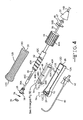
- FIG. 1 illustrates a bi-directional catheter assembly 10 according to the present invention.
- the bi-directional catheter assembly 10 comprises a handle assembly 12 supporting a deflectable sheath 14.
- the deflectable sheath 14 comprises an elongate tubular structure that is flexible yet substantially non-compressible along its length.
- the deflectable sheath 14 extends from a deflectable distal end 14A ( FIG. 1 ), which is adapted to be disposed within a patient, to a proximal portion 14B.
- the sheath 14 includes a delivery lumen 14C ( FIGs. 9 and 10 ) that extends through the sheath body from the deflectable distal end 14A to the proximal portion 14B.
- An exemplary construction for the sheath 14 comprises an outer tubular member 16 formed of a polymeric material, such as of PEBAX, encasing a tubular wire braided 18 as a mesh.
- An inner liner 20 of a second polymeric material, for example PTFE resides inside the outer PEBAX tube 16.
- the PTFE liner 20 provides the sheath lumen 14C with sufficient lubricity so that medical instruments, devices, and the like, slide through the sheath 14 with a minimal amount of force.
- the delivery lumen 14C is sized and shaped to receive, for example, instruments, fluids, media, and the like.
- the handle assembly 12 provides for selective deflection of the distal end 14A of the sheath 14 into anyone of a number of disparate orientations, as will be further described in detail herein below.
- the handle assembly 12 includes a lower handle portion 12A mated to an upper handle portion 12B. This mated relationship is effected by posts or protrusions 22 extending upwardly at spaced intervals along an edge of the lower handle portion 12A.
- the posts 22 are snap-fit into mating receptacles (not shown) on a corresponding edge of the upper handle portion 12B.
- Threaded openings 23 are also provided in the lower handle portion 12A. They receive threaded fasteners (not shown) to further help secure the handle portion 12A and 12B together.
- the mated lower and upper handle portions 12A and 12B provide an ergonomically curved sidewall, the extent of which is defined by a handle proximal end wall 12C and a handle distal end wall 12D.
- the handle proximal end wall 12A includes a semi-circular opening 24.
- the handle distal end wall 12D has a semi-circular opening 26 therein.
- a hub 28 is over-molded onto the proximal end 30A of an elongate inner tube 30.
- the opposite, distal end 30B of the inner tube is received in a nose cone 32 where it connects to the proximal end 14B of the sheath 14 in an open communication manner.
- the hub 28 has a tapered inner shape that serves to funnel and direct instruments and the like into a lumen 30C ( FIGs. 6 to 9 ) provided through the tube 30 and in communication with the sheath lumen 14C.
- the sheath 14 and inner tube 30 provide a sheath means with open communication from the hub 28 to and through the deflectable distal sheath end 14A.
- a sealable membrane 34 is seated against the proximal hub portion, captured there by a cap 36.
- the cap 36 has an annular groove (not shown) that snap-fits into engagement with an annular protrusion (not shown) on the outer wall of the hub 28.
- a side port 38 exits through the wall of the hub 28.
- the side port 38 allows for introduction of fluids, such as saline or medicine, into and through the lumen 30C of the elongate tube 30 and into and through the sheath lumen 14C without having to remove instruments disposed through the tube and sheath lumens.
- a flexible tube 40 provided with a 3-way valve 42 is connected to the port 38 to facilitate selective introduction of fluids therein.
- the elongate inner tube 30 supports an outer anchor rod 40 as a tubular structure that is somewhat shorter in length than the inner tube.
- the outer anchor rod 40 supports a threaded screw 42 that is connected to a distal thumb wheel 44.
- a pair of diametrically opposed axially aligned slots 40B, 40C extend through the wall thickness of the outer anchor rod 40 at a position proximal to the threaded screw 42.
- the threaded screw 42 is provided with thread grooves 42A extending distally from the proximal end 42B along a majority of its length, but ending short of an unthreaded distal portion 42C thereof.
- the thumb wheel 44 and the threaded screw 42 are connected together as a unitary construction. Consequently, rotational movement of the thumb wheel 44 causes the threaded screw 42 to rotate in a similar direction and at a similar rate.
- Axially aligned ridges 44A are spaced radially about the periphery of the thumb wheel 44. The ridges 44A serve as gripping surfaces to provide a physician using the present catheter 10 with better tactile feel.
- a washer 46 resides on the inner tube 30.
- An abutment nose 47 is mounted on the inner tube 30 intermediate the washer 46 and the nose cone 32.
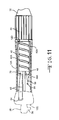
- a slider block 48 is translationally supported on an inner surface 12E of the lower and lower handle portions 12A, 12B
- the slider block 48 is confined in this position bu opposed abutments 49A, 49B. That way, the slider block 48 is translationally or axially, but not rotationally, movable along the handle 12.
- the slider block 48 has a U-shaped cross-section extending from an open distal end 48A to a wall 48B at its proximal end.
- the proximal wall 48B is provided with a curved inlet 48C sized to permit the inner tube 30 to rest therein.
- An inner surface 50 of the slider block 48 is provided with at least one thread protrusion 50A.
- the threaded protrusion 50A has a height and shape that matches the depth and pitch of the threaded grooves 42A of the threaded member 42.
- the lower handle portion 12A is provided with an internal wall 52 aligned perpendicular to the longitudinal axis of the handle 12 and positioned adjacent to the proximal semi-circular opening 24.
- the internal wall 52 supports a proximally extending protrusion 52A spaced inwardly from upper and lower stepped webs 52B, 52C.
- the inner wall 52 in conjunction with the protrusion 52A and stepped webs 52B, 52C define a space that retains a U-shaped tube 54 therein ( FIGs. 5A to 5C ).
- the proximal wall 48B of the slider block 48 is provided with spaced apart openings 56A and 56B through the thickness thereof and aligned parallel to the longitudinal axis of the slider block and the handle 12.
- the openings 56A and 56B are provided on either side of curved inlet 48C.
- a first pull wire 58 extends through the first opening 56A and along a portion of the length of the slider block 48 until it enters inlet slot 40B provided through the wall thickness of the outer anchor rod 40. From there, the first pull wire 58 extends along an annulus 60 formed between the outer surface of the inner tube 30 and the inner surface of the anchor rod 40 and then between the outer tubular member 16 and the inner liner 20 of the sheath 14. The first pull wire 58 terminates in an anchor 62 provided in the deflectable distal end 14A of the sheath. The opposite, proximal end 58A of the first pull wire 58 is received in a first anchor pin 64, serving as a first stop member, and held in place by set screw 66. The first anchor pin 64 abuts against a proximal surface of the proximal slider block wall 48B.
- the proximal end 68A of a second pull wire 68 is received in a second anchor pin 70, serving as a second stop member, and held in place by set screw 72.
- the second anchor pin 70 abuts against a distal surface of the proximal slider block wall 48A, opposite the proximal surface thereof against which the first anchor pin 64 abuts.
- the second pull wire 68 extends through the second opening 56B in the proximal slider block wall 48B and through a lumen 54A provided by the U-shaped tube 54 nested in the lower handle portion 12A between the protrusion 52A and the opposed stepped webs 52B, 52C extending from the inner wall 52.
- the second pull wire 68 extends along a portion of the length of the slide block 48 until it enters inlet slot 40C provided through the thickness of the outer anchor rod 40.
- the hypo-tube 54 changes the direction and point of application of a pulling force applied to the second pull wire 68, as will be described in detail herein after.
- the second pull wire 68 extends along the annulus 60 between the outer surface of the inner tube 30 and the inner surface of the anchor rod 40 and then between the outer tubular member 16 and the inner liner 20 of the sheath 14.
- the second pull wire 68 terminates in an anchor 74 provided in the deflectable distal end 14A of the sheath, opposite the first pull wire 58 and its terminus anchor 62.
- the first and second pull wires 58, 68 can be made of such disparate materials as stainless steel, NITINOL ® , or flexible polymers and textile materials such as VECTRAN ® or Spectra.
- the U-shaped tube 54 is an improvement over the prior art where pulleys, posts, and the like are used as change-of-direction structures. These convention structures do not confine and contain the pull wire as it travels back and forth across the pulley or post. That is not the case with the present U-shaped tube 54 which does confine and contain that pull wire 68 therein.
- first and second anchor pins 64, 70 secured to the ends of the first and second pull wires 58, 68 serve as stops for their respective pull wires.
- pulling forces imparted to the wires 58, 68 by manipulation of the rotatable knob 44 of the handle assembly 12 are transmitted by one or the other of the pull wires 58, 68 to the deflectable distal end 14A of the sheath 14 to cause deflection thereof in an intended manner.
- the present bi-directional sheath assembly 10 provides for deflectable movement of the distal end 14A through a wide range both above and below a longitudinal axis defines by the longitudinal axis of the sheath distal end 14A. This deflectional motion is affected by rotational movement of the rotatable knob 44 in either a clockwise or counter clockwise direction.
- this drawing shows the position of the slider block 48 with respect to the first and second anchor pins 64 and 70 secured to the proximal ends of the respective pull wires 58, 68.
- the deflectable distal end 14A of the sheath is in a generally horizontal position, neither deflecting upwardly or downwardly, but aligned along the longitudinal axis of the sheath distal end.
- the knob 44 is rotated in a clockwise direction.
- This causes the slider block 48 threadingly engaged with the threaded screw 42 to translate along the lower handle portion 12A in a forward direction towards the distal end 12D of the handle 12.
- the second anchor pin 70 contacting the distal surface of the proximal slider block wall 48A causes the adjacent portion of the second pull wire 68 to move in a forwardly direction out from the lumen 54A of the hypo-tube 54.
- the remainder of the second pull wire moves in a rearwardly direction into the hypo-tube lumen 54A. As this occurs, force is transferred to the distal end of the pull wire 58 and its distal anchor 62 ( FIG. 9 ), thereby causing the distal end 14A of the sheath 14 ( FIG. 2 ) to deflect upwardly 14D.
- the second pull wire 68 does not move during this manipulation. Instead, it is stiff enough to maintain its "at rest" shape shown in FIG. 9 .
- Rotation of the knob 44 in an opposite, counter clockwise direction releases pressure from the second anchor pin 70 as the threaded screw 42 rotates, causing the slider block 48 to begin moving in a proximal direction.
- the slider block 48 is back to the neutral position shown in FIG 2 , the distal sheath end 14A relaxes into its neutral, longitudinal orientation ( FIG. 1 ), nether deflecting upwardly or downwardly.
- the knob 44 is rotated in a counter clockwise direction.
- This causes the slider block 48 threadingly engaged with the counter clockwise rotating threaded screw 42 to translate along the lower handle portion 12A in a rearward direction towards the proximal end 12C of the handle 12.
- the first anchor pin 64 secured to the proximal end of the first pull wire 58 and abutting against the proximal surface of the proximal slider block wall 48A moves in a rearwardly direction.
- pull wires 58, 68 are only secured to the deflectable sheath 14 at their respective distal anchors 62, 74. The remainder of their lengths reside between the outer tubular member 16 of the sheath and the previously described inner liner 20 forming the sheath lumen 14C. In any event, there is a "space" between the sheath tubular member 16 and the liner 20 that permits movement of the pull wires there along.
- the present invention provides a physician with a sheath assembly 10 that is capable of readily deflecting the distal sheath end 14A in any one of a myriad of directions, both upwardly and downwardly with respect to a longitudinal axis thereof.
- This provides the physician with a great degree of flexibility in maneuvering the distal end 14A of the sheath for performing a medical procedure inside the vasculature of a patient.
- the translational movement of the slider block 48 in a backward and forward direction to effect deflection movement of the sheath distal end 14A is built into a handle assembly 12 having a relatively compact size.
Landscapes
- Health & Medical Sciences (AREA)
- Life Sciences & Earth Sciences (AREA)
- Engineering & Computer Science (AREA)
- Hematology (AREA)
- Pulmonology (AREA)
- Anesthesiology (AREA)
- Biomedical Technology (AREA)
- Heart & Thoracic Surgery (AREA)
- Biophysics (AREA)
- Animal Behavior & Ethology (AREA)
- General Health & Medical Sciences (AREA)
- Public Health (AREA)
- Veterinary Medicine (AREA)
- Mechanical Engineering (AREA)
- Media Introduction/Drainage Providing Device (AREA)
- Surgical Instruments (AREA)
Applications Claiming Priority (1)
| Application Number | Priority Date | Filing Date | Title |
|---|---|---|---|
| US39121610P | 2010-10-08 | 2010-10-08 |
Publications (3)
| Publication Number | Publication Date |
|---|---|
| EP2438954A1 true EP2438954A1 (de) | 2012-04-11 |
| EP2438954A8 EP2438954A8 (de) | 2012-06-13 |
| EP2438954B1 EP2438954B1 (de) | 2016-12-28 |
Family
ID=44993439
Family Applications (1)
| Application Number | Title | Priority Date | Filing Date |
|---|---|---|---|
| EP11008171.8A Active EP2438954B1 (de) | 2010-10-08 | 2011-10-10 | Bidirektionaler Katheterlenkgriff |
Country Status (2)
| Country | Link |
|---|---|
| US (1) | US9149607B2 (de) |
| EP (1) | EP2438954B1 (de) |
Cited By (14)
| Publication number | Priority date | Publication date | Assignee | Title |
|---|---|---|---|---|
| US20130165857A1 (en) * | 2011-12-22 | 2013-06-27 | Joseph A. O'Donnell | Handle having hub with rotating infusion sideport |
| WO2013190475A3 (en) * | 2012-06-19 | 2014-03-13 | Baylis Medical Company Inc. | Steerable medical device handle |
| WO2014166968A1 (en) * | 2013-04-08 | 2014-10-16 | Cardio3 Biosciences S.A. | Steering control mechanism for catheter |
| WO2014150077A3 (en) * | 2013-03-15 | 2014-12-04 | Lucent Medical Systems, Inc. | Partially disposable endoscopic device |
| EP2859907A1 (de) * | 2013-10-10 | 2015-04-15 | Oscor Inc. | Lenkbare medizinische Vorrichtungen |
| CN104958824A (zh) * | 2015-07-30 | 2015-10-07 | 湖南埃普特医疗器械有限公司 | 一种导引导管 |
| CN105636634A (zh) * | 2013-09-30 | 2016-06-01 | 圣犹达医疗用品心脏病学部门有限公司 | 具有主动回直机构的导管 |
| US9700699B2 (en) | 2014-09-12 | 2017-07-11 | Freudenberg Medical, Llc | Modular handle assembly for a steerable catheter |
| US9737688B2 (en) | 2014-09-12 | 2017-08-22 | Freudenberg Medical, Llc | Modular handle assembly for a steerable catheter |
| EP3275498A1 (de) * | 2013-04-30 | 2018-01-31 | St. Jude Medical Luxembourg Holding S.à.r.l. | Steuergriffe für katheter |
| US11357953B2 (en) | 2016-12-22 | 2022-06-14 | Baylis Medical Company Inc. | Feedback mechanisms for a steerable medical device |
| US11571547B2 (en) | 2013-12-20 | 2023-02-07 | Boston Scientific Medical Device Limited | Steerable medical device handle |
| US11918762B2 (en) | 2018-10-03 | 2024-03-05 | St. Jude Medical, Cardiology Division, Inc. | Reduced actuation force electrophysiology catheter handle |
| USD1034977S1 (en) | 2021-07-23 | 2024-07-09 | Ipg Photonics Corporation | Control handle grip for a catheter |
Families Citing this family (135)
| Publication number | Priority date | Publication date | Assignee | Title |
|---|---|---|---|---|
| WO2006097931A2 (en) | 2005-03-17 | 2006-09-21 | Valtech Cardio, Ltd. | Mitral valve treatment techniques |
| US11259924B2 (en) | 2006-12-05 | 2022-03-01 | Valtech Cardio Ltd. | Implantation of repair devices in the heart |
| US9883943B2 (en) | 2006-12-05 | 2018-02-06 | Valtech Cardio, Ltd. | Implantation of repair devices in the heart |
| US11660190B2 (en) | 2007-03-13 | 2023-05-30 | Edwards Lifesciences Corporation | Tissue anchors, systems and methods, and devices |
| US8382829B1 (en) | 2008-03-10 | 2013-02-26 | Mitralign, Inc. | Method to reduce mitral regurgitation by cinching the commissure of the mitral valve |
| US8652202B2 (en) | 2008-08-22 | 2014-02-18 | Edwards Lifesciences Corporation | Prosthetic heart valve and delivery apparatus |
| US8715342B2 (en) | 2009-05-07 | 2014-05-06 | Valtech Cardio, Ltd. | Annuloplasty ring with intra-ring anchoring |
| US8545553B2 (en) | 2009-05-04 | 2013-10-01 | Valtech Cardio, Ltd. | Over-wire rotation tool |
| EP3848002A1 (de) | 2008-12-22 | 2021-07-14 | Valtech Cardio, Ltd. | Einstellbare annuloplastievorrichtungen und einstellmechanismen dafür |
| US8241351B2 (en) | 2008-12-22 | 2012-08-14 | Valtech Cardio, Ltd. | Adjustable partial annuloplasty ring and mechanism therefor |
| US10517719B2 (en) | 2008-12-22 | 2019-12-31 | Valtech Cardio, Ltd. | Implantation of repair devices in the heart |
| US8353956B2 (en) | 2009-02-17 | 2013-01-15 | Valtech Cardio, Ltd. | Actively-engageable movement-restriction mechanism for use with an annuloplasty structure |
| US9968452B2 (en) | 2009-05-04 | 2018-05-15 | Valtech Cardio, Ltd. | Annuloplasty ring delivery cathethers |
| US12485010B2 (en) | 2009-05-07 | 2025-12-02 | Edwards Lifesciences Innovation (Israel) Ltd. | Multiple anchor delivery tool |
| US10098737B2 (en) | 2009-10-29 | 2018-10-16 | Valtech Cardio, Ltd. | Tissue anchor for annuloplasty device |
| US9180007B2 (en) | 2009-10-29 | 2015-11-10 | Valtech Cardio, Ltd. | Apparatus and method for guide-wire based advancement of an adjustable implant |
| US8734467B2 (en) | 2009-12-02 | 2014-05-27 | Valtech Cardio, Ltd. | Delivery tool for implantation of spool assembly coupled to a helical anchor |
| US8449599B2 (en) | 2009-12-04 | 2013-05-28 | Edwards Lifesciences Corporation | Prosthetic valve for replacing mitral valve |
| US10792152B2 (en) | 2011-06-23 | 2020-10-06 | Valtech Cardio, Ltd. | Closed band for percutaneous annuloplasty |
| EP2723274B1 (de) | 2011-06-23 | 2017-12-27 | Valtech Cardio, Ltd. | Verschlusselement zur verwendung mit einer annuloplastiestruktur |
| US8858623B2 (en) | 2011-11-04 | 2014-10-14 | Valtech Cardio, Ltd. | Implant having multiple rotational assemblies |
| EP3970627B1 (de) | 2011-11-08 | 2023-12-20 | Edwards Lifesciences Innovation (Israel) Ltd. | Gesteuerte lenkfunktionalität für ein implantatabgabewerkzeug |
| CN104203157B (zh) | 2011-12-12 | 2016-02-03 | 戴维·阿隆 | 心脏瓣膜修补器械 |
| US9821143B2 (en) | 2011-12-15 | 2017-11-21 | Imricor Medical Systems, Inc. | Steerable sheath including elastomeric member |
| US9757538B2 (en) | 2011-12-15 | 2017-09-12 | Imricor Medical Systems, Inc. | MRI compatible control handle for steerable sheath with audible, tactile and/or visual means |
| WO2013090558A1 (en) | 2011-12-15 | 2013-06-20 | Imricor Medical Systems, Inc. | Mri compatible handle and steerable sheath |
| CN103566454B (zh) * | 2012-08-01 | 2015-09-09 | 四川锦江电子科技有限公司 | 双控弯手柄 |
| CN103565518B (zh) * | 2012-08-01 | 2015-09-02 | 四川锦江电子科技有限公司 | 双控弯电生理导管 |
| CA2885354A1 (en) | 2012-09-29 | 2014-04-03 | Mitralign, Inc. | Plication lock delivery system and method of use thereof |
| WO2014064694A2 (en) | 2012-10-23 | 2014-05-01 | Valtech Cardio, Ltd. | Controlled steering functionality for implant-delivery tool |
| US10376266B2 (en) | 2012-10-23 | 2019-08-13 | Valtech Cardio, Ltd. | Percutaneous tissue anchor techniques |
| WO2014087402A1 (en) | 2012-12-06 | 2014-06-12 | Valtech Cardio, Ltd. | Techniques for guide-wire based advancement of a tool |
| US9439763B2 (en) | 2013-02-04 | 2016-09-13 | Edwards Lifesciences Corporation | Prosthetic valve for replacing mitral valve |
| EP2961351B1 (de) | 2013-02-26 | 2018-11-28 | Mitralign, Inc. | Vorrichtungen zur perkutanen reparatur der trikuspidalklappe |
| US10449333B2 (en) | 2013-03-14 | 2019-10-22 | Valtech Cardio, Ltd. | Guidewire feeder |
| WO2014152503A1 (en) | 2013-03-15 | 2014-09-25 | Mitralign, Inc. | Translation catheters, systems, and methods of use thereof |
| WO2014162442A1 (ja) * | 2013-04-01 | 2014-10-09 | テルモ株式会社 | 作動部材、および医療器具 |
| US9855404B2 (en) | 2013-05-03 | 2018-01-02 | St. Jude Medical International Holding S.À R.L. | Dual bend radii steering catheter |
| US10070857B2 (en) | 2013-08-31 | 2018-09-11 | Mitralign, Inc. | Devices and methods for locating and implanting tissue anchors at mitral valve commissure |
| AU2013403325B2 (en) * | 2013-10-15 | 2019-07-18 | Stryker Corporation | Device for creating a void space in a living tissue, the device including a handle with a control knob that can be set regardless of the orientation of the handle |
| US10299793B2 (en) | 2013-10-23 | 2019-05-28 | Valtech Cardio, Ltd. | Anchor magazine |
| US9622863B2 (en) | 2013-11-22 | 2017-04-18 | Edwards Lifesciences Corporation | Aortic insufficiency repair device and method |
| US9610162B2 (en) | 2013-12-26 | 2017-04-04 | Valtech Cardio, Ltd. | Implantation of flexible implant |
| CN103920227A (zh) * | 2014-04-22 | 2014-07-16 | 高峰 | 可调弯多功能冠脉指引导管 |
| WO2016033403A1 (en) * | 2014-08-29 | 2016-03-03 | Endochoice, Inc. | Systems and methods for varying stiffness of an endoscopic insertion tube |
| WO2016036774A1 (en) * | 2014-09-01 | 2016-03-10 | Clph, Llc | Steerable catheters and methods for making them |
| EP3206629B1 (de) | 2014-10-14 | 2021-07-14 | Valtech Cardio, Ltd. | Vorrichtung zur rückhaltung von herzklappensegel |
| CN111437068B (zh) | 2014-12-04 | 2023-01-17 | 爱德华兹生命科学公司 | 用于修复心脏瓣膜的经皮夹具 |
| US10188833B2 (en) * | 2015-01-21 | 2019-01-29 | Medtronic Vascular, Inc. | Guide catheter with steering mechanisms |
| US20160256269A1 (en) | 2015-03-05 | 2016-09-08 | Mitralign, Inc. | Devices for treating paravalvular leakage and methods use thereof |
| WO2016158171A1 (ja) * | 2015-03-27 | 2016-10-06 | テルモ株式会社 | カテーテル組立体 |
| EP3288496B1 (de) | 2015-04-30 | 2024-05-29 | Edwards Lifesciences Innovation (Israel) Ltd. | Technologien für die annuloplastie |
| ES3001450T3 (en) | 2015-05-14 | 2025-03-05 | Edwards Lifesciences Corp | Heart valve sealing devices and delivery devices therefor |
| WO2017117370A2 (en) | 2015-12-30 | 2017-07-06 | Mitralign, Inc. | System and method for reducing tricuspid regurgitation |
| US10835714B2 (en) * | 2016-03-21 | 2020-11-17 | Edwards Lifesciences Corporation | Multi-direction steerable handles for steering catheters |
| US10799675B2 (en) * | 2016-03-21 | 2020-10-13 | Edwards Lifesciences Corporation | Cam controlled multi-direction steerable handles |
| US10799676B2 (en) | 2016-03-21 | 2020-10-13 | Edwards Lifesciences Corporation | Multi-direction steerable handles for steering catheters |
| US10799677B2 (en) | 2016-03-21 | 2020-10-13 | Edwards Lifesciences Corporation | Multi-direction steerable handles for steering catheters |
| US11219746B2 (en) | 2016-03-21 | 2022-01-11 | Edwards Lifesciences Corporation | Multi-direction steerable handles for steering catheters |
| US10702274B2 (en) | 2016-05-26 | 2020-07-07 | Edwards Lifesciences Corporation | Method and system for closing left atrial appendage |
| US10973638B2 (en) | 2016-07-07 | 2021-04-13 | Edwards Lifesciences Corporation | Device and method for treating vascular insufficiency |
| GB201611910D0 (en) | 2016-07-08 | 2016-08-24 | Valtech Cardio Ltd | Adjustable annuloplasty device with alternating peaks and troughs |
| US10653862B2 (en) | 2016-11-07 | 2020-05-19 | Edwards Lifesciences Corporation | Apparatus for the introduction and manipulation of multiple telescoping catheters |
| JP6693861B2 (ja) * | 2016-12-21 | 2020-05-13 | 日本ライフライン株式会社 | 医療機器用ハンドルおよび医療機器 |
| CN108261256B (zh) * | 2016-12-31 | 2024-05-07 | 深圳市健心医疗科技有限公司 | 输送装置及输送系统 |
| US10905554B2 (en) | 2017-01-05 | 2021-02-02 | Edwards Lifesciences Corporation | Heart valve coaptation device |
| US10786651B2 (en) | 2017-03-07 | 2020-09-29 | Talon Medical, LLC | Steerable guide catheter |
| US10709870B2 (en) | 2017-03-14 | 2020-07-14 | Greatbatch Ltd. | Steerable medical device and method |
| US11045627B2 (en) | 2017-04-18 | 2021-06-29 | Edwards Lifesciences Corporation | Catheter system with linear actuation control mechanism |
| PL3558169T3 (pl) | 2017-04-18 | 2022-04-04 | Edwards Lifesciences Corporation | Urządzenia do uszczelniania zastawki serca i urządzenia do ich doprowadzania |
| US11224511B2 (en) | 2017-04-18 | 2022-01-18 | Edwards Lifesciences Corporation | Heart valve sealing devices and delivery devices therefor |
| US10799312B2 (en) | 2017-04-28 | 2020-10-13 | Edwards Lifesciences Corporation | Medical device stabilizing apparatus and method of use |
| US10959846B2 (en) | 2017-05-10 | 2021-03-30 | Edwards Lifesciences Corporation | Mitral valve spacer device |
| US11051940B2 (en) | 2017-09-07 | 2021-07-06 | Edwards Lifesciences Corporation | Prosthetic spacer device for heart valve |
| US11065117B2 (en) | 2017-09-08 | 2021-07-20 | Edwards Lifesciences Corporation | Axisymmetric adjustable device for treating mitral regurgitation |
| US11110251B2 (en) | 2017-09-19 | 2021-09-07 | Edwards Lifesciences Corporation | Multi-direction steerable handles for steering catheters |
| US10894145B2 (en) | 2017-09-22 | 2021-01-19 | Cook Medical Technologies Llc | Steerable catheter system with hub |
| US10835221B2 (en) | 2017-11-02 | 2020-11-17 | Valtech Cardio, Ltd. | Implant-cinching devices and systems |
| US11135062B2 (en) | 2017-11-20 | 2021-10-05 | Valtech Cardio Ltd. | Cinching of dilated heart muscle |
| US10231837B1 (en) | 2018-01-09 | 2019-03-19 | Edwards Lifesciences Corporation | Native valve repair devices and procedures |
| US10973639B2 (en) | 2018-01-09 | 2021-04-13 | Edwards Lifesciences Corporation | Native valve repair devices and procedures |
| US10245144B1 (en) | 2018-01-09 | 2019-04-02 | Edwards Lifesciences Corporation | Native valve repair devices and procedures |
| US10159570B1 (en) | 2018-01-09 | 2018-12-25 | Edwards Lifesciences Corporation | Native valve repair devices and procedures |
| US10123873B1 (en) | 2018-01-09 | 2018-11-13 | Edwards Lifesciences Corporation | Native valve repair devices and procedures |
| US10136993B1 (en) | 2018-01-09 | 2018-11-27 | Edwards Lifesciences Corporation | Native valve repair devices and procedures |
| JP7343393B2 (ja) | 2018-01-09 | 2023-09-12 | エドワーズ ライフサイエンシーズ コーポレイション | 天然心臓弁修復装置および処置 |
| US10238493B1 (en) | 2018-01-09 | 2019-03-26 | Edwards Lifesciences Corporation | Native valve repair devices and procedures |
| US10076415B1 (en) | 2018-01-09 | 2018-09-18 | Edwards Lifesciences Corporation | Native valve repair devices and procedures |
| US10111751B1 (en) | 2018-01-09 | 2018-10-30 | Edwards Lifesciences Corporation | Native valve repair devices and procedures |
| US10105222B1 (en) | 2018-01-09 | 2018-10-23 | Edwards Lifesciences Corporation | Native valve repair devices and procedures |
| CN111655200B (zh) | 2018-01-24 | 2023-07-14 | 爱德华兹生命科学创新(以色列)有限公司 | 瓣环成形术结构的收缩 |
| WO2019145941A1 (en) | 2018-01-26 | 2019-08-01 | Valtech Cardio, Ltd. | Techniques for facilitating heart valve tethering and chord replacement |
| US11389297B2 (en) | 2018-04-12 | 2022-07-19 | Edwards Lifesciences Corporation | Mitral valve spacer device |
| US11207181B2 (en) | 2018-04-18 | 2021-12-28 | Edwards Lifesciences Corporation | Heart valve sealing devices and delivery devices therefor |
| US12156979B2 (en) * | 2018-05-21 | 2024-12-03 | St. Jude Medical, Cardiology Division, Inc. | Deflectable catheter shaft with pullwire anchor feature |
| JP7387731B2 (ja) | 2018-07-12 | 2023-11-28 | エドワーズ ライフサイエンシーズ イノベーション (イスラエル) リミテッド | 弁輪形成システムおよびそのための係止ツール |
| US10945844B2 (en) | 2018-10-10 | 2021-03-16 | Edwards Lifesciences Corporation | Heart valve sealing devices and delivery devices therefor |
| EP3883500B1 (de) | 2018-11-20 | 2024-11-06 | Edwards Lifesciences Corporation | Freisetzungswerkzeuge zur freisetzung einer vorrichtung in einer nativen herzklappe |
| CN113301869A (zh) | 2018-11-21 | 2021-08-24 | 爱德华兹生命科学公司 | 心脏瓣膜密封装置、其递送装置以及取回装置 |
| CR20210312A (es) | 2018-11-29 | 2021-09-14 | Edwards Lifesciences Corp | Método y aparato de cateterización |
| CA3125227A1 (en) | 2019-01-11 | 2020-07-16 | Dragonfly Endoscopy Llc | Endoscopic device and methods of use thereof |
| CN113747858B (zh) | 2019-02-11 | 2024-11-01 | 爱德华兹生命科学公司 | 心脏瓣膜密封装置及其递送装置 |
| WO2020168081A1 (en) | 2019-02-14 | 2020-08-20 | Edwards Lifesciences Corporation | Heart valve sealing devices and delivery devices therefor |
| SG11202108606PA (en) | 2019-02-25 | 2021-09-29 | Edwards Lifesciences Corp | Heart valve sealing devices |
| CN113395989B (zh) | 2019-02-25 | 2023-08-11 | 爱德华兹生命科学公司 | 用于导丝的调整机构和方法 |
| US11357570B2 (en) | 2019-04-19 | 2022-06-14 | Lake Region Manufacturing, Inc. | Ablation catheter with fiber Bragg grating strain sensors |
| WO2020219392A2 (en) | 2019-04-24 | 2020-10-29 | Stryker Corporation | Systems and methods for off-axis augmentation of a vertebral body |
| AU2020284630A1 (en) | 2019-05-29 | 2021-11-18 | Edwards Lifesciences Innovation (Israel) Ltd. | Tissue anchor handling systems and methods |
| US12178583B2 (en) | 2019-06-07 | 2024-12-31 | Lake Region Manufacturing, Inc. | Basket-type EP catheter with electrode polling for sequential electrode sampling |
| US11446470B2 (en) * | 2019-06-24 | 2022-09-20 | Medtronic, Inc. | Catheter handle with torque mechanism and valve relief component |
| US12502167B2 (en) | 2019-07-16 | 2025-12-23 | Edwards Lifesciences Corporation | Tissue remodeling systems and methods |
| US12364606B2 (en) | 2019-07-23 | 2025-07-22 | Edwards Lifesciences Innovation (Israel) Ltd. | Fluoroscopic visualization of heart valve anatomy |
| WO2021014440A2 (en) | 2019-07-23 | 2021-01-28 | Valtech Cardio, Ltd. | Contraction of an annuloplasty structure |
| CN114258313A (zh) | 2019-08-28 | 2022-03-29 | 瓦尔泰克卡迪欧有限公司 | 低剖面可转向导管 |
| JP2022546160A (ja) | 2019-08-30 | 2022-11-04 | エドワーズ ライフサイエンシーズ イノベーション (イスラエル) リミテッド | アンカーチャネル先端 |
| CN111150933B (zh) * | 2019-09-02 | 2022-08-09 | 杭州神络医疗科技有限公司 | 导管电极和体内植入神经刺激装置 |
| EP3789071A1 (de) * | 2019-09-03 | 2021-03-10 | Creganna Unlimited Company | Griff für eine medizinische vorrichtung zum artikulieren eines katheters |
| KR20220066398A (ko) | 2019-09-25 | 2022-05-24 | 카디악 임플란츠 엘엘씨 | 심장 판막 고리 감소 시스템 |
| US12558079B2 (en) * | 2019-10-07 | 2026-02-24 | St. Jude Medical, Cardiology Division, Inc. | Catheter including wire management cap and methods of assembling same |
| CA3143014A1 (en) | 2019-10-15 | 2021-04-22 | Edwards Lifesciences Corporation | Heart valve sealing devices and delivery devices therefor |
| WO2021084407A1 (en) | 2019-10-29 | 2021-05-06 | Valtech Cardio, Ltd. | Annuloplasty and tissue anchor technologies |
| JP2023516439A (ja) | 2020-03-04 | 2023-04-19 | シファメド・ホールディングス・エルエルシー | 血栓除去システムおよび関連の方法 |
| EP4096529B1 (de) | 2020-03-23 | 2025-05-07 | Edwards Lifesciences Innovation (Israel) Ltd. | Selbstsichernde winde |
| WO2021236634A2 (en) | 2020-05-20 | 2021-11-25 | Cardiac Implants, Llc | Reducing the diameter of a cardiac valve annulus with independent control over each of the anchors that are launched into the annulus |
| CA3182316A1 (en) | 2020-06-19 | 2021-12-23 | Edwards Lifesciences Innovation (Israel) Ltd. | Self-stopping tissue anchors |
| WO2022009094A1 (en) * | 2020-07-08 | 2022-01-13 | Baylis Medical Company Inc. | Steerable medical device, handle for a medical device, and method for operating a medical device |
| WO2022009096A1 (en) * | 2020-07-08 | 2022-01-13 | Baylis Medical Company Inc. | Steerable medical device, handle for a medical device, and method for operating a medical device |
| WO2022051241A1 (en) | 2020-09-01 | 2022-03-10 | Edwards Lifesciences Corporation | Medical device stabilizing systems |
| WO2022074478A1 (en) * | 2020-10-09 | 2022-04-14 | Baylis Medical Company Inc. | Steerable medical device, handle for a medical device, and method for operating a medical device |
| US11585706B2 (en) | 2020-10-14 | 2023-02-21 | Lake Region Manufacturing, Inc. | Guidewire with fiber Bragg grating strain sensors |
| WO2022246071A2 (en) | 2021-05-19 | 2022-11-24 | Shifamed Holdings, Llc | Thrombus removal systems and associated methods |
| US12521527B2 (en) * | 2021-05-28 | 2026-01-13 | Medtronic Vascular, Inc. | Steerable catheter device |
| CN114849017A (zh) * | 2022-06-08 | 2022-08-05 | 环心医疗科技(苏州)有限公司 | 可控弯导管及其控制手柄 |
| USD1071198S1 (en) | 2023-06-28 | 2025-04-15 | Edwards Lifesciences Corporation | Cradle |
| WO2025085924A1 (en) * | 2023-10-19 | 2025-04-24 | Shifamed Holdings, Llc | Systems, methods, and apparatuses for deflection state in medical catheters |
Citations (7)
| Publication number | Priority date | Publication date | Assignee | Title |
|---|---|---|---|---|
| US5571085A (en) * | 1995-03-24 | 1996-11-05 | Electro-Catheter Corporation | Steerable open lumen catheter |
| EP0904797A2 (de) * | 1997-09-24 | 1999-03-31 | Eclipse Surgical Technologies, Inc. | Lenkbaker katheter mit Spitzenausrichtung unf Flächekontaktdetektor |
| WO2000067834A1 (en) * | 1999-05-11 | 2000-11-16 | Zynergy Cardiovascular, Inc. | Steerable catheter |
| US20030109861A1 (en) * | 2001-04-12 | 2003-06-12 | Jin Shimada | Steerable sheath catheters |
| EP1676595A1 (de) * | 2004-12-28 | 2006-07-05 | St. Jude Medical, Atrial Fibrillation Division, Inc. | Bidirektionaler Bedienungshandgriff für einen steuerbaren Katheter |
| US20070260223A1 (en) * | 2006-05-03 | 2007-11-08 | Scheibe Grant A | Deflectable sheath handle assembly and method therefor |
| EP1897581A2 (de) * | 2003-09-02 | 2008-03-12 | St. Jude Medical, Cardiology Division, Inc. | Vorrichtungen und Verfahren zur Durchkreuzung eines vollständigen chronischen Verschlusses |
Family Cites Families (7)
| Publication number | Priority date | Publication date | Assignee | Title |
|---|---|---|---|---|
| NL9301018A (nl) * | 1993-06-11 | 1995-01-02 | Cordis Europ | Bestuurd buigbare catheter. |
| US5944690A (en) | 1997-03-17 | 1999-08-31 | C.R. Bard, Inc. | Slidable control mechanism for steerable catheter |
| US6663588B2 (en) | 2000-11-29 | 2003-12-16 | C.R. Bard, Inc. | Active counterforce handle for use in bidirectional deflectable tip instruments |
| US7591784B2 (en) | 2005-04-26 | 2009-09-22 | St. Jude Medical, Atrial Fibrillation Division, Inc. | Bi-directional handle for a catheter |
| US7931616B2 (en) | 2006-10-31 | 2011-04-26 | Biosense Webster, Inc. | Insert molded catheter puller member connectors and method of making |
| US8308659B2 (en) | 2008-05-09 | 2012-11-13 | Greatbatch Ltd. | Bi-directional sheath deflection mechanism |
| US8137308B2 (en) | 2008-09-16 | 2012-03-20 | Biosense Webster, Inc. | Catheter with adjustable deflection sensitivity |
-
2011
- 2011-10-10 EP EP11008171.8A patent/EP2438954B1/de active Active
- 2011-10-10 US US13/269,858 patent/US9149607B2/en active Active
Patent Citations (7)
| Publication number | Priority date | Publication date | Assignee | Title |
|---|---|---|---|---|
| US5571085A (en) * | 1995-03-24 | 1996-11-05 | Electro-Catheter Corporation | Steerable open lumen catheter |
| EP0904797A2 (de) * | 1997-09-24 | 1999-03-31 | Eclipse Surgical Technologies, Inc. | Lenkbaker katheter mit Spitzenausrichtung unf Flächekontaktdetektor |
| WO2000067834A1 (en) * | 1999-05-11 | 2000-11-16 | Zynergy Cardiovascular, Inc. | Steerable catheter |
| US20030109861A1 (en) * | 2001-04-12 | 2003-06-12 | Jin Shimada | Steerable sheath catheters |
| EP1897581A2 (de) * | 2003-09-02 | 2008-03-12 | St. Jude Medical, Cardiology Division, Inc. | Vorrichtungen und Verfahren zur Durchkreuzung eines vollständigen chronischen Verschlusses |
| EP1676595A1 (de) * | 2004-12-28 | 2006-07-05 | St. Jude Medical, Atrial Fibrillation Division, Inc. | Bidirektionaler Bedienungshandgriff für einen steuerbaren Katheter |
| US20070260223A1 (en) * | 2006-05-03 | 2007-11-08 | Scheibe Grant A | Deflectable sheath handle assembly and method therefor |
Cited By (27)
| Publication number | Priority date | Publication date | Assignee | Title |
|---|---|---|---|---|
| WO2013096676A1 (en) * | 2011-12-22 | 2013-06-27 | Boston Scientific Scimed, Inc. | Steerable sheath handle pulley mechanism |
| US8911397B2 (en) | 2011-12-22 | 2014-12-16 | Boston Scientific Scimed Inc. | Steerable sheath handle pulley mechanism |
| US20130165857A1 (en) * | 2011-12-22 | 2013-06-27 | Joseph A. O'Donnell | Handle having hub with rotating infusion sideport |
| US9149608B2 (en) * | 2011-12-22 | 2015-10-06 | Boston Scientific Scimed Inc. | Handle having hub with rotating infusion sideport |
| US12370346B2 (en) | 2012-06-19 | 2025-07-29 | Boston Scientific Medical Device Limited | Steerable medical device handle |
| WO2013190475A3 (en) * | 2012-06-19 | 2014-03-13 | Baylis Medical Company Inc. | Steerable medical device handle |
| JP2019013777A (ja) * | 2012-06-19 | 2019-01-31 | ベイリス メディカル カンパニー インコーポレイテッドBaylis Medical Company Inc. | 操縦可能な医療デバイスハンドル |
| US10806896B2 (en) | 2012-06-19 | 2020-10-20 | Baylis Medical Company Inc. | Steerable medical device handle |
| WO2014150077A3 (en) * | 2013-03-15 | 2014-12-04 | Lucent Medical Systems, Inc. | Partially disposable endoscopic device |
| US10835713B2 (en) | 2013-04-08 | 2020-11-17 | Celyad S.A. | Steering control mechanism for catheter |
| AU2014253150B2 (en) * | 2013-04-08 | 2019-01-17 | Celyad S.A. | Steering control mechanism for catheter |
| WO2014166968A1 (en) * | 2013-04-08 | 2014-10-16 | Cardio3 Biosciences S.A. | Steering control mechanism for catheter |
| EP3275498A1 (de) * | 2013-04-30 | 2018-01-31 | St. Jude Medical Luxembourg Holding S.à.r.l. | Steuergriffe für katheter |
| CN105636634A (zh) * | 2013-09-30 | 2016-06-01 | 圣犹达医疗用品心脏病学部门有限公司 | 具有主动回直机构的导管 |
| US10898686B2 (en) | 2013-09-30 | 2021-01-26 | St. Jude Medical, Cardiology Division, Inc. | Catheter having an active return-to-straight mechanism |
| US10118021B2 (en) | 2013-09-30 | 2018-11-06 | St. Jude Medical, Cardiology Division, Inc. | Catheter having an active return-to-straight mechanism |
| CN105636634B (zh) * | 2013-09-30 | 2019-02-01 | 圣犹达医疗用品心脏病学部门有限公司 | 具有主动回直机构的导管 |
| EP2859907A1 (de) * | 2013-10-10 | 2015-04-15 | Oscor Inc. | Lenkbare medizinische Vorrichtungen |
| US11571547B2 (en) | 2013-12-20 | 2023-02-07 | Boston Scientific Medical Device Limited | Steerable medical device handle |
| US12257401B2 (en) | 2013-12-20 | 2025-03-25 | Boston Scientific Medical Device Limited | Steerable medical device handle |
| US10806897B2 (en) | 2014-09-12 | 2020-10-20 | Freudenberg Medical, Llc | Modular handle assembly for a steerable catheter |
| US9737688B2 (en) | 2014-09-12 | 2017-08-22 | Freudenberg Medical, Llc | Modular handle assembly for a steerable catheter |
| US9700699B2 (en) | 2014-09-12 | 2017-07-11 | Freudenberg Medical, Llc | Modular handle assembly for a steerable catheter |
| CN104958824A (zh) * | 2015-07-30 | 2015-10-07 | 湖南埃普特医疗器械有限公司 | 一种导引导管 |
| US11357953B2 (en) | 2016-12-22 | 2022-06-14 | Baylis Medical Company Inc. | Feedback mechanisms for a steerable medical device |
| US11918762B2 (en) | 2018-10-03 | 2024-03-05 | St. Jude Medical, Cardiology Division, Inc. | Reduced actuation force electrophysiology catheter handle |
| USD1034977S1 (en) | 2021-07-23 | 2024-07-09 | Ipg Photonics Corporation | Control handle grip for a catheter |
Also Published As
| Publication number | Publication date |
|---|---|
| US20120089125A1 (en) | 2012-04-12 |
| US9149607B2 (en) | 2015-10-06 |
| EP2438954A8 (de) | 2012-06-13 |
| EP2438954B1 (de) | 2016-12-28 |
Similar Documents
| Publication | Publication Date | Title |
|---|---|---|
| EP2438954B1 (de) | Bidirektionaler Katheterlenkgriff | |
| EP2116272B1 (de) | Zweidirektionaler Hülsenlenkmechanismus | |
| US11344702B2 (en) | Steerable sheath | |
| AU2008202483B2 (en) | A deflectable stylet | |
| US20210008347A1 (en) | Catheter assembly with segmented stabilization system | |
| US7615044B2 (en) | Deflectable sheath handle assembly and method therefor | |
| EP2204208B1 (de) | Lenkbarer Schleuseneinführer | |
| CN111315435B (zh) | 可转向装置和系统 | |
| RU2648028C2 (ru) | Устройство для биопсии и способ применения | |
| DE69020140T2 (de) | Steuerbare medizinische anordnung. | |
| US20110208215A1 (en) | Devices, methods, and kits for forming tracts in tissue | |
| US9962184B2 (en) | Fast-acting or rotating transseptal needle | |
| JP2015536226A (ja) | 操縦可能ガイドワイヤおよび使用方法 | |
| JP2009537280A (ja) | 可動医療器具 | |
| CN110913763A (zh) | 可操纵引导导管 | |
| US9636480B2 (en) | Steerable catheters |
Legal Events
| Date | Code | Title | Description |
|---|---|---|---|
| AK | Designated contracting states |
Kind code of ref document: A1 Designated state(s): AL AT BE BG CH CY CZ DE DK EE ES FI FR GB GR HR HU IE IS IT LI LT LU LV MC MK MT NL NO PL PT RO RS SE SI SK SM TR |
|
| AX | Request for extension of the european patent |
Extension state: BA ME |
|
| PUAI | Public reference made under article 153(3) epc to a published international application that has entered the european phase |
Free format text: ORIGINAL CODE: 0009012 |
|
| 17P | Request for examination filed |
Effective date: 20120514 |
|
| 17Q | First examination report despatched |
Effective date: 20130820 |
|
| GRAP | Despatch of communication of intention to grant a patent |
Free format text: ORIGINAL CODE: EPIDOSNIGR1 |
|
| INTG | Intention to grant announced |
Effective date: 20160622 |
|
| GRAJ | Information related to disapproval of communication of intention to grant by the applicant or resumption of examination proceedings by the epo deleted |
Free format text: ORIGINAL CODE: EPIDOSDIGR1 |
|
| GRAS | Grant fee paid |
Free format text: ORIGINAL CODE: EPIDOSNIGR3 |
|
| INTC | Intention to grant announced (deleted) | ||
| RIN1 | Information on inventor provided before grant (corrected) |
Inventor name: SCHEIBE, GRANT Inventor name: OPBROEK, AARON Inventor name: KAMPA, NICK Inventor name: WALCH, TOM Inventor name: NELSON, MARK |
|
| GRAP | Despatch of communication of intention to grant a patent |
Free format text: ORIGINAL CODE: EPIDOSNIGR1 |
|
| INTG | Intention to grant announced |
Effective date: 20161028 |
|
| GRAA | (expected) grant |
Free format text: ORIGINAL CODE: 0009210 |
|
| AK | Designated contracting states |
Kind code of ref document: B1 Designated state(s): AL AT BE BG CH CY CZ DE DK EE ES FI FR GB GR HR HU IE IS IT LI LT LU LV MC MK MT NL NO PL PT RO RS SE SI SK SM TR |
|
| REG | Reference to a national code |
Ref country code: GB Ref legal event code: FG4D |
|
| REG | Reference to a national code |
Ref country code: CH Ref legal event code: EP |
|
| REG | Reference to a national code |
Ref country code: AT Ref legal event code: REF Ref document number: 856775 Country of ref document: AT Kind code of ref document: T Effective date: 20170115 |
|
| REG | Reference to a national code |
Ref country code: IE Ref legal event code: FG4D |
|
| REG | Reference to a national code |
Ref country code: DE Ref legal event code: R096 Ref document number: 602011033761 Country of ref document: DE |
|
| PG25 | Lapsed in a contracting state [announced via postgrant information from national office to epo] |
Ref country code: LV Free format text: LAPSE BECAUSE OF FAILURE TO SUBMIT A TRANSLATION OF THE DESCRIPTION OR TO PAY THE FEE WITHIN THE PRESCRIBED TIME-LIMIT Effective date: 20161228 |
|
| REG | Reference to a national code |
Ref country code: LT Ref legal event code: MG4D |
|
| PG25 | Lapsed in a contracting state [announced via postgrant information from national office to epo] |
Ref country code: SE Free format text: LAPSE BECAUSE OF FAILURE TO SUBMIT A TRANSLATION OF THE DESCRIPTION OR TO PAY THE FEE WITHIN THE PRESCRIBED TIME-LIMIT Effective date: 20161228 Ref country code: LT Free format text: LAPSE BECAUSE OF FAILURE TO SUBMIT A TRANSLATION OF THE DESCRIPTION OR TO PAY THE FEE WITHIN THE PRESCRIBED TIME-LIMIT Effective date: 20161228 Ref country code: NO Free format text: LAPSE BECAUSE OF FAILURE TO SUBMIT A TRANSLATION OF THE DESCRIPTION OR TO PAY THE FEE WITHIN THE PRESCRIBED TIME-LIMIT Effective date: 20170328 Ref country code: GR Free format text: LAPSE BECAUSE OF FAILURE TO SUBMIT A TRANSLATION OF THE DESCRIPTION OR TO PAY THE FEE WITHIN THE PRESCRIBED TIME-LIMIT Effective date: 20170329 |
|
| REG | Reference to a national code |
Ref country code: AT Ref legal event code: MK05 Ref document number: 856775 Country of ref document: AT Kind code of ref document: T Effective date: 20161228 |
|
| PG25 | Lapsed in a contracting state [announced via postgrant information from national office to epo] |
Ref country code: RS Free format text: LAPSE BECAUSE OF FAILURE TO SUBMIT A TRANSLATION OF THE DESCRIPTION OR TO PAY THE FEE WITHIN THE PRESCRIBED TIME-LIMIT Effective date: 20161228 Ref country code: HR Free format text: LAPSE BECAUSE OF FAILURE TO SUBMIT A TRANSLATION OF THE DESCRIPTION OR TO PAY THE FEE WITHIN THE PRESCRIBED TIME-LIMIT Effective date: 20161228 Ref country code: FI Free format text: LAPSE BECAUSE OF FAILURE TO SUBMIT A TRANSLATION OF THE DESCRIPTION OR TO PAY THE FEE WITHIN THE PRESCRIBED TIME-LIMIT Effective date: 20161228 |
|
| PG25 | Lapsed in a contracting state [announced via postgrant information from national office to epo] |
Ref country code: NL Free format text: LAPSE BECAUSE OF FAILURE TO SUBMIT A TRANSLATION OF THE DESCRIPTION OR TO PAY THE FEE WITHIN THE PRESCRIBED TIME-LIMIT Effective date: 20161228 |
|
| PG25 | Lapsed in a contracting state [announced via postgrant information from national office to epo] |
Ref country code: SK Free format text: LAPSE BECAUSE OF FAILURE TO SUBMIT A TRANSLATION OF THE DESCRIPTION OR TO PAY THE FEE WITHIN THE PRESCRIBED TIME-LIMIT Effective date: 20161228 Ref country code: RO Free format text: LAPSE BECAUSE OF FAILURE TO SUBMIT A TRANSLATION OF THE DESCRIPTION OR TO PAY THE FEE WITHIN THE PRESCRIBED TIME-LIMIT Effective date: 20161228 Ref country code: IS Free format text: LAPSE BECAUSE OF FAILURE TO SUBMIT A TRANSLATION OF THE DESCRIPTION OR TO PAY THE FEE WITHIN THE PRESCRIBED TIME-LIMIT Effective date: 20170428 Ref country code: EE Free format text: LAPSE BECAUSE OF FAILURE TO SUBMIT A TRANSLATION OF THE DESCRIPTION OR TO PAY THE FEE WITHIN THE PRESCRIBED TIME-LIMIT Effective date: 20161228 Ref country code: CZ Free format text: LAPSE BECAUSE OF FAILURE TO SUBMIT A TRANSLATION OF THE DESCRIPTION OR TO PAY THE FEE WITHIN THE PRESCRIBED TIME-LIMIT Effective date: 20161228 |
|
| PG25 | Lapsed in a contracting state [announced via postgrant information from national office to epo] |
Ref country code: ES Free format text: LAPSE BECAUSE OF FAILURE TO SUBMIT A TRANSLATION OF THE DESCRIPTION OR TO PAY THE FEE WITHIN THE PRESCRIBED TIME-LIMIT Effective date: 20161228 Ref country code: BG Free format text: LAPSE BECAUSE OF FAILURE TO SUBMIT A TRANSLATION OF THE DESCRIPTION OR TO PAY THE FEE WITHIN THE PRESCRIBED TIME-LIMIT Effective date: 20170328 Ref country code: PL Free format text: LAPSE BECAUSE OF FAILURE TO SUBMIT A TRANSLATION OF THE DESCRIPTION OR TO PAY THE FEE WITHIN THE PRESCRIBED TIME-LIMIT Effective date: 20161228 Ref country code: AT Free format text: LAPSE BECAUSE OF FAILURE TO SUBMIT A TRANSLATION OF THE DESCRIPTION OR TO PAY THE FEE WITHIN THE PRESCRIBED TIME-LIMIT Effective date: 20161228 Ref country code: BE Free format text: LAPSE BECAUSE OF FAILURE TO SUBMIT A TRANSLATION OF THE DESCRIPTION OR TO PAY THE FEE WITHIN THE PRESCRIBED TIME-LIMIT Effective date: 20161228 Ref country code: IT Free format text: LAPSE BECAUSE OF FAILURE TO SUBMIT A TRANSLATION OF THE DESCRIPTION OR TO PAY THE FEE WITHIN THE PRESCRIBED TIME-LIMIT Effective date: 20161228 Ref country code: SM Free format text: LAPSE BECAUSE OF FAILURE TO SUBMIT A TRANSLATION OF THE DESCRIPTION OR TO PAY THE FEE WITHIN THE PRESCRIBED TIME-LIMIT Effective date: 20161228 Ref country code: PT Free format text: LAPSE BECAUSE OF FAILURE TO SUBMIT A TRANSLATION OF THE DESCRIPTION OR TO PAY THE FEE WITHIN THE PRESCRIBED TIME-LIMIT Effective date: 20170428 |
|
| REG | Reference to a national code |
Ref country code: FR Ref legal event code: PLFP Year of fee payment: 7 |
|
| REG | Reference to a national code |
Ref country code: DE Ref legal event code: R097 Ref document number: 602011033761 Country of ref document: DE |
|
| PLBE | No opposition filed within time limit |
Free format text: ORIGINAL CODE: 0009261 |
|
| STAA | Information on the status of an ep patent application or granted ep patent |
Free format text: STATUS: NO OPPOSITION FILED WITHIN TIME LIMIT |
|
| PG25 | Lapsed in a contracting state [announced via postgrant information from national office to epo] |
Ref country code: DK Free format text: LAPSE BECAUSE OF FAILURE TO SUBMIT A TRANSLATION OF THE DESCRIPTION OR TO PAY THE FEE WITHIN THE PRESCRIBED TIME-LIMIT Effective date: 20161228 |
|
| 26N | No opposition filed |
Effective date: 20170929 |
|
| PG25 | Lapsed in a contracting state [announced via postgrant information from national office to epo] |
Ref country code: SI Free format text: LAPSE BECAUSE OF FAILURE TO SUBMIT A TRANSLATION OF THE DESCRIPTION OR TO PAY THE FEE WITHIN THE PRESCRIBED TIME-LIMIT Effective date: 20161228 |
|
| PG25 | Lapsed in a contracting state [announced via postgrant information from national office to epo] |
Ref country code: MC Free format text: LAPSE BECAUSE OF FAILURE TO SUBMIT A TRANSLATION OF THE DESCRIPTION OR TO PAY THE FEE WITHIN THE PRESCRIBED TIME-LIMIT Effective date: 20161228 |
|
| REG | Reference to a national code |
Ref country code: CH Ref legal event code: PL |
|
| GBPC | Gb: european patent ceased through non-payment of renewal fee |
Effective date: 20171010 |
|
| REG | Reference to a national code |
Ref country code: IE Ref legal event code: MM4A |
|
| PG25 | Lapsed in a contracting state [announced via postgrant information from national office to epo] |
Ref country code: LU Free format text: LAPSE BECAUSE OF NON-PAYMENT OF DUE FEES Effective date: 20171010 Ref country code: GB Free format text: LAPSE BECAUSE OF NON-PAYMENT OF DUE FEES Effective date: 20171010 Ref country code: CH Free format text: LAPSE BECAUSE OF NON-PAYMENT OF DUE FEES Effective date: 20171031 Ref country code: LI Free format text: LAPSE BECAUSE OF NON-PAYMENT OF DUE FEES Effective date: 20171031 |
|
| REG | Reference to a national code |
Ref country code: FR Ref legal event code: PLFP Year of fee payment: 8 |
|
| PG25 | Lapsed in a contracting state [announced via postgrant information from national office to epo] |
Ref country code: MT Free format text: LAPSE BECAUSE OF NON-PAYMENT OF DUE FEES Effective date: 20171010 |
|
| PG25 | Lapsed in a contracting state [announced via postgrant information from national office to epo] |
Ref country code: IE Free format text: LAPSE BECAUSE OF NON-PAYMENT OF DUE FEES Effective date: 20171010 |
|
| PG25 | Lapsed in a contracting state [announced via postgrant information from national office to epo] |
Ref country code: HU Free format text: LAPSE BECAUSE OF FAILURE TO SUBMIT A TRANSLATION OF THE DESCRIPTION OR TO PAY THE FEE WITHIN THE PRESCRIBED TIME-LIMIT; INVALID AB INITIO Effective date: 20111010 |
|
| PG25 | Lapsed in a contracting state [announced via postgrant information from national office to epo] |
Ref country code: CY Free format text: LAPSE BECAUSE OF NON-PAYMENT OF DUE FEES Effective date: 20161228 |
|
| PG25 | Lapsed in a contracting state [announced via postgrant information from national office to epo] |
Ref country code: MK Free format text: LAPSE BECAUSE OF FAILURE TO SUBMIT A TRANSLATION OF THE DESCRIPTION OR TO PAY THE FEE WITHIN THE PRESCRIBED TIME-LIMIT Effective date: 20161228 |
|
| PG25 | Lapsed in a contracting state [announced via postgrant information from national office to epo] |
Ref country code: TR Free format text: LAPSE BECAUSE OF FAILURE TO SUBMIT A TRANSLATION OF THE DESCRIPTION OR TO PAY THE FEE WITHIN THE PRESCRIBED TIME-LIMIT Effective date: 20161228 |
|
| PG25 | Lapsed in a contracting state [announced via postgrant information from national office to epo] |
Ref country code: AL Free format text: LAPSE BECAUSE OF FAILURE TO SUBMIT A TRANSLATION OF THE DESCRIPTION OR TO PAY THE FEE WITHIN THE PRESCRIBED TIME-LIMIT Effective date: 20161228 |
|
| PGFP | Annual fee paid to national office [announced via postgrant information from national office to epo] |
Ref country code: FR Payment date: 20230911 Year of fee payment: 13 |
|
| PG25 | Lapsed in a contracting state [announced via postgrant information from national office to epo] |
Ref country code: FR Free format text: LAPSE BECAUSE OF NON-PAYMENT OF DUE FEES Effective date: 20241031 |
|
| PGFP | Annual fee paid to national office [announced via postgrant information from national office to epo] |
Ref country code: DE Payment date: 20250902 Year of fee payment: 15 |