EP2438974B1 - Schwimmfähige Reinigungsanordnung - Google Patents
Schwimmfähige Reinigungsanordnung Download PDFInfo
- Publication number
- EP2438974B1 EP2438974B1 EP10186500.4A EP10186500A EP2438974B1 EP 2438974 B1 EP2438974 B1 EP 2438974B1 EP 10186500 A EP10186500 A EP 10186500A EP 2438974 B1 EP2438974 B1 EP 2438974B1
- Authority
- EP
- European Patent Office
- Prior art keywords
- floatable
- cleaning assembly
- floating body
- filtering device
- receiving container
- Prior art date
- Legal status (The legal status is an assumption and is not a legal conclusion. Google has not performed a legal analysis and makes no representation as to the accuracy of the status listed.)
- Not-in-force
Links
Images

Classifications
-
- B—PERFORMING OPERATIONS; TRANSPORTING
- B01—PHYSICAL OR CHEMICAL PROCESSES OR APPARATUS IN GENERAL
- B01D—SEPARATION
- B01D35/00—Filtering devices having features not specifically covered by groups B01D24/00 - B01D33/00, or for applications not specifically covered by groups B01D24/00 - B01D33/00; Auxiliary devices for filtration; Filter housing constructions
- B01D35/05—Floating filters
-
- G—PHYSICS
- G21—NUCLEAR PHYSICS; NUCLEAR ENGINEERING
- G21C—NUCLEAR REACTORS
- G21C19/00—Arrangements for treating, for handling, or for facilitating the handling of, fuel or other materials which are used within the reactor, e.g. within its pressure vessel
- G21C19/02—Details of handling arrangements
- G21C19/06—Magazines for holding fuel elements or control elements
- G21C19/07—Storage racks; Storage pools
-
- G—PHYSICS
- G21—NUCLEAR PHYSICS; NUCLEAR ENGINEERING
- G21C—NUCLEAR REACTORS
- G21C19/00—Arrangements for treating, for handling, or for facilitating the handling of, fuel or other materials which are used within the reactor, e.g. within its pressure vessel
- G21C19/28—Arrangements for introducing fluent material into the reactor core; Arrangements for removing fluent material from the reactor core
- G21C19/30—Arrangements for introducing fluent material into the reactor core; Arrangements for removing fluent material from the reactor core with continuous purification of circulating fluent material, e.g. by extraction of fission products deterioration or corrosion products, impurities, e.g. by cold traps
- G21C19/307—Arrangements for introducing fluent material into the reactor core; Arrangements for removing fluent material from the reactor core with continuous purification of circulating fluent material, e.g. by extraction of fission products deterioration or corrosion products, impurities, e.g. by cold traps specially adapted for liquids
-
- G—PHYSICS
- G21—NUCLEAR PHYSICS; NUCLEAR ENGINEERING
- G21F—PROTECTION AGAINST X-RADIATION, GAMMA RADIATION, CORPUSCULAR RADIATION OR PARTICLE BOMBARDMENT; TREATING RADIOACTIVELY CONTAMINATED MATERIAL; DECONTAMINATION ARRANGEMENTS THEREFOR
- G21F9/00—Treating radioactively contaminated material; Decontamination arrangements therefor
- G21F9/001—Decontamination of contaminated objects, apparatus, clothes, food; Preventing contamination thereof
- G21F9/002—Decontamination of the surface of objects with chemical or electrochemical processes
- G21F9/004—Decontamination of the surface of objects with chemical or electrochemical processes of metallic surfaces
-
- G—PHYSICS
- G21—NUCLEAR PHYSICS; NUCLEAR ENGINEERING
- G21F—PROTECTION AGAINST X-RADIATION, GAMMA RADIATION, CORPUSCULAR RADIATION OR PARTICLE BOMBARDMENT; TREATING RADIOACTIVELY CONTAMINATED MATERIAL; DECONTAMINATION ARRANGEMENTS THEREFOR
- G21F9/00—Treating radioactively contaminated material; Decontamination arrangements therefor
- G21F9/04—Treating liquids
-
- Y—GENERAL TAGGING OF NEW TECHNOLOGICAL DEVELOPMENTS; GENERAL TAGGING OF CROSS-SECTIONAL TECHNOLOGIES SPANNING OVER SEVERAL SECTIONS OF THE IPC; TECHNICAL SUBJECTS COVERED BY FORMER USPC CROSS-REFERENCE ART COLLECTIONS [XRACs] AND DIGESTS
- Y02—TECHNOLOGIES OR APPLICATIONS FOR MITIGATION OR ADAPTATION AGAINST CLIMATE CHANGE
- Y02E—REDUCTION OF GREENHOUSE GAS [GHG] EMISSIONS, RELATED TO ENERGY GENERATION, TRANSMISSION OR DISTRIBUTION
- Y02E30/00—Energy generation of nuclear origin
- Y02E30/30—Nuclear fission reactors
Definitions
- the present invention relates to a buoyant cleaning system designed for use in fuel and / or reactor basins of nuclear power plants.
- the applicant describes a filter device which is arranged in a liquid to be filtered and which has a frame, at least one pump connected to the frame and a suction device connected to the suction side of the pump.
- the filter device further comprises at least one filter having an inlet side, the inlet side being connected to the pressure side of the pump; a freestanding outlet side of the filter through which the filtrate is discharged from the filter substantially directly in the liquid to be filtered; a detachable connection between filter inlet and pump pressure side through which the filter can be disconnected from the device; and an automatically controllable actuator directly or indirectly attached to the frame for actuating the releasable connection.
- the cleaning process in this case comprises the pressing of the liquid through a filter which is arranged in a frame in the liquid container; the delivery of a filtrate from the filter directly back into the liquid container; moving the frame with the loaded filter via a filter receiving device and uncoupling the loaded filter from the frame and transferring the filter into the filter receiving device.
- the object of the present invention is to provide a cleaning system with which the changing operation for the known filter device (or also another suitable filter device) becomes more flexible, i. away from the edge of the pool, and without it being necessary to support the corresponding exchangeable devices on surrounding structures (such as, for example, walls).
- a floatable cleaning system in particular for use in fuel and reactor basins of nuclear power plants, comprising one or more floats, a filter device which is detachably connected to the float or floats, a changing device or receptacle for receiving the Filter device, wherein the container for receiving the filter device is connected via manipulation means to the float, wherein the manipulation means are adapted such that they can bring the receptacle to a position below the filter device to receive them, and by a method for replacing a filter device by means a floatable cleaning system comprising the steps of: positioning the receptacle below the filter device by manipulating the manipulating means, releasing the filter device by actuating a stop generating device, collecting the dissolved filter device in the receptacle and transporting the filter device into a position for changing the filter device by actuation of the manipulation means.
- the float (or floats) consists of one or more multi-chamber system (s).
- An inventive multi-chamber system preferably has between two and sixteen chambers. Embodiments with more chambers are however conceivable.
- the float may also consist of two interconnected runners or tubes, each of an equal number of chambers. However, embodiments with multiple runners or tubes, each with the same or different numbers of chambers are possible.
- the multi-chamber system is designed such that the floating body remains buoyant even in the case of damage of up to 25% (ie the chambers). This is achieved by a corresponding number of chambers in coordination with the buoyancy force required for the entire device. In this way, the high safety standards that apply when handling contaminated media are taken into account.
- the float is made of a corrosion resistant material, e.g. B. a plastic material.
- a corrosion resistant material e.g. B. a plastic material.
- a relatively low weight of the float can be achieved.
- stainless steel which are better to clean or decontaminate.
- the float has holding means to connect the float with a pool edge can. If necessary, the position of the floating body in the corresponding basin can be additionally stabilized by the retaining means (eg ropes or rods).
- the filter device is connected via a suspension and a holding device to the float.
- the filter device in conjunction with a suitable drive means, can be moved in any case in the Z-plane.
- the suspension is regularly designed as a linkage or rope device. Incidentally, it can also be made movable in the X and Y planes.
- the mounting device consists at least of a bracket and a locking mechanism.
- the bracket serves to hold the filter device and the locking mechanism is used to lock or release the filter device.
- the locking mechanism preferably consists of a pivotable hook arrangement, which can be moved approximately via a guide linkage, wherein the hook assembly cooperates with corresponding flanges on the filter assembly.
- the manipulation means for the receptacle consist of a lifting device.
- the lifting device can move the receiving container for the filtering device in the X, Y and Z directions to bring it into a position (eg at the surface) that allows the filter or filter elements to be replaced.
- the lifting device comprises a joint function for the receptacle to pivot it after receiving the filter device so that it can be lifted without colliding with the float.
- the buoyant cleaning system is configured collapsible. In this way, the system can be loaded and transported in the manner of a pontoon bridge.
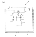
- FIG. 1 the inventive floating cleaning system 1 is illustrated schematically.
- the floating body 4 is arranged in a tank 10 filled with a liquid 12 to be cleaned.
- the floating body 4 is fastened by means of the holding means 4 on the edge of the pool 11 of the basin 10 in order to stabilize its floating position.
- the floating body 4 is connected via the suspension 7 and the mounting device 8 with the filter device 2.
- the mounting device 8 is regularly made of a bracket 8a and a locking mechanism 8b.
- the bracket 8a serves to hold the filter device and in turn is connected to the suspension 7.
- the suspension 7 is connected to the float 4, wherein in or on the float a motor or drive unit M is arranged, which, as needed, movements of the suspension in the Z-plane but also in the X and Y plane can allow.
- the suspension 7 is regularly formed as a linkage or rope device; However, other forms of suspension are conceivable.
- the locking mechanism 8b is usually formed of a plurality of guide plates and hooks which cooperate with corresponding flanges on the filter device 2 (not shown). However, there are also other positive, non-positive or frictional, possibly also magnetic, locking mechanisms conceivable.
- the locking mechanism 8b can be actuated via the motor or drive unit M or by a separate drive unit. When the locking mechanism 8b is opened, the filter device 2 is released and can sink down in the liquid 12, where it is possibly collected by the receptacle 3.
- the receptacle 3 is located usual way in the form of a barrel made of plastic or stainless steel and is connected via the manipulation means 5 with the float 4.
- the manipulation means 5 are regularly formed in the form of a lifting device, which, as required, allows movement of the receptacle 3 in the X, Y or Z plane.
- the manipulation means 5 can also be designed in the form of a linkage or a cable device.
- the manipulation means 5 can also include a hinge 9 by means of which the receptacle 3 can be pivoted so that it does not collide when lifting if necessary with the floating body 4.
- the manipulation means 5 can be actuated by a further motor or drive unit M, which, however, can also be combined in one unit with the motor or drive unit M for the mounting device 8.
- the respective motor or drive units M can be controlled by a control device (not shown) outside of the basin 10.
- a typical change process for the filter device 2 or of filter elements of the filter device runs on the basis of the following steps: First, the receptacle 3 is positioned below the filter device 2 by operating the manipulation means 5. Subsequently, the filter device 2 by actuation of the holding device 8 (or the Locking mechanism 8b) solved, d. H. the holding device 8 is brought into a release position. The thus released or released filter device can now be collected in the receptacle 3. Finally, the filter device 2 is transported to a position for changing the filter device 2 by actuation of the manipulation means 5. It is more usual to change the filter device 2 or the filter elements on the liquid surface at the edge 11. The loading with the replaced filter device 2 takes place in the opposite direction Sequence.
- FIGS. 2a-c Various embodiments of the floating body 4 according to the invention are illustrated.
- Fig. 2a shows one rectangular floating body 4.
- Fig. 2b shows an embodiment with two separate floats 4, which, in the manner of a catamaran, via two webs 13 are interconnected.
- the webs 13 can be formed from the same material as the floating body (eg plastic) or from another material (eg metal). They can be hollow or massive.
- the floating body 4 is formed in the manner of a floating ring. Which form is ultimately used depends on the manner in which the manipulation means 5 and the holding device and the associated motor or drive units are arranged on the floating body and on the manner of the folding mechanism.
- ⁇ U> REFERENCE LIST ⁇ / u> 1 Floatable cleaning system 2 filter means 3 Receiving container or changing device 4 float 5 manipulation means 6 holding means 7 suspension 8th mounting device 8a hanger 8b locking mechanism 9 joint function 10 pool 11 Poolside 12 liquid 13 Stege M Motor or drive unit
Landscapes
- Engineering & Computer Science (AREA)
- Physics & Mathematics (AREA)
- High Energy & Nuclear Physics (AREA)
- General Engineering & Computer Science (AREA)
- Chemical Kinetics & Catalysis (AREA)
- Plasma & Fusion (AREA)
- Chemical & Material Sciences (AREA)
- General Chemical & Material Sciences (AREA)
- Food Science & Technology (AREA)
- Life Sciences & Earth Sciences (AREA)
- Electrochemistry (AREA)
- Water Supply & Treatment (AREA)
- Filtration Of Liquid (AREA)
Description
- Die vorliegende Erfindung betrifft ein schwimmfähiges Reinigungssystem, welches für die Verwendung in Brennelement- und/oder Reaktorbecken von Kernkraftwerken konzipiert wurde.
- In der europäischen Patentschrift
EP 0 247 325 B1 der Anmelderin wird eine Filtervorrichtung beschrieben, welche in einer zu filternden Flüssigkeit angeordnet ist und welche einen Rahmen, zumindest eine mit dem Rahmen verbundene Pumpe und eine mit der Ansaugseite der Pumpe verbundene Ansaugeinrichtung aufweist. Die Filtervorrichtung umfasst des Weiteren zumindest einen Filter mit einer Einlassseite, wobei die Einlassseite mit der Druckseite der Pumpe verbunden ist; eine freistehende Auslassseite des Filters durch die das Filtrat von dem Filter im Wesentlichen direkt in der zu filternden Flüssigkeit wieder abgegeben wird; eine lösbare Verbindung zwischen Filtereinlass und Pumpendruckseite durch die das Filter von der Vorrichtung abgekoppelt werden kann; und eine direkt oder indirekt an dem Rahmen befestigte automatisch steuerbare Betätigungsvorrichtung zur Betätigung der lösbaren Verbindung. Der Reinigungsvorgang umfasst dabei das Pressen der Flüssigkeit durch ein Filter, das in einem Rahmen in dem Flüssigkeitsbehälter angeordnet ist; die Abgabe eines Filtrats von dem Filter direkt zurück in den Flüssigkeitsbehälter; das Bewegen des Rahmens mit dem beladenen Filter über eine Filteraufnahmevorrichtung sowie das Abkoppeln des beladenen Filters von dem Rahmen und Übertragung des Filters in die Filteraufnahmeeinrichtung. - Aufgabe der vorliegenden Erfindung ist es, ein Reinigungssystem bereitzustellen, mit dem der Wechselvorgang für die bekannte Filtervorrichtung (oder auch eine andere geeignete Filtervorrichtung) flexibler, d.h. vom Beckenrand entfernt, zu gestalten und ohne dass es dabei einer Abstützung der entsprechenden Wechseleinrichtungen an umliegenden Strukturen (wie z. B. Wänden) bedarf.
- Diese Aufgabe wird erfindungsgemäß gelöst durch ein schwimmfähiges Reinigungssystem, insbesondere zur Verwendung in Brennelement- und Reaktorbecken von Kernkraftwerken, aufweisend einen oder mehrere Schwimmkörper, eine Filtervorrichtung, welche lösbar mit dem Schwimmkörper bzw. den Schwimmkörpern verbunden ist, eine Wechselvorrichtung bzw. Aufnahmebehälter zur Aufnahme der Filtervorrichtung, wobei der Behälter zur Aufnahme der Filtervorrichtung über Manipulationsmittel mit dem Schwimmkörper verbunden ist, wobei die Manipulationsmittel derart ausgestaltet sind, dass sie den Aufnahmebehälter in eine Position unterhalb der Filtervorrichtung bringen können, um diese aufzunehmen, sowie durch ein Verfahren zum Auswechseln einer Filtervorrichtung mittels eines schwimmfähigen Reinigungssystems mit den Schritten: Positionieren des Aufnahmebehälters unterhalb der Filtervorrichtung durch Betätigung der Manipulationsmittel, Lösen der Filtervorrichtung durch Betätigung einer Halterungsvorrichtung, Auffangen der gelösten Filtervorrichtung in dem Aufnahmebehälter und Transport der Filtervorrichtung in eine Position zum Wechseln der Filtervorrichtung durch Betätigung der Manipulationsmittel.
- In einer bevorzugten Ausführungsform der Erfindung besteht der Schwimmkörper (bzw. die Schwimmkörper) aus einem bzw. mehreren Mehrkammersystem(en). Ein erfindungsgemäßes Mehrkammersystem weist vorzugsweise zwischen zwei und sechzehn Kammern auf. Ausführungsformen mit mehr Kammern sind allerdings denkbar. Der Schwimmkörper kann auch aus zwei miteinander verbundenen Kufen oder Rohren bestehen, welche jeweils eine gleiche Anzahl von Kammern aufweisen. Allerdings sind auch Ausführungsformen mit mehreren Kufen oder Rohren mit jeweils gleichen oder unterschiedlichen Anzahlen an Kammern möglich.
- In einer weiteren bevorzugten Ausführungsform der Erfindung ist das Mehrkammersystem so ausgestaltet, dass der Schwimmkörper auch bei Beschädigungen von bis zu 25% (d. h. der Kammern) schwimmfähig bleibt. Dies wird erreicht durch eine entsprechende Kammeranzahl in Abstimmung mit der für die gesamte Vorrichtung benötigten Auftriebskraft. Auf diese Weise wird den hohen Sicherheitsstandards, die beim Umgang mit kontaminierten Medien gelten, Rechnung getragen.
- In einer noch weiteren bevorzugten Ausführungsform der Erfindung ist der Schwimmkörper aus einem korrosionsresistenten Material, z. B. einem Kunststoffmaterial, gebildet. Hierdurch kann ein relativ niedriges Gewicht des Schwimmkörpers erreicht werden. Es sind allerdings auch Ausführungsformen aus Edelstahl denkbar, welche besser zu reinigen bzw. dekontaminieren sind.
- In einer anderen bevorzugten Ausführungsform der Erfindung verfügt der Schwimmkörper über Haltemittel, um den Schwimmkörper mit einem Beckenrand verbinden zu können. Durch die Haltemittel (z. B. Seile oder Stangen) kann bei Bedarf die Lage des Schwimmkörpers in dem entsprechenden Becken zusätzlich stabilisiert werden.
- In einer weiteren bevorzugten Ausführungsform der Erfindung ist die Filtervorrichtung über eine Aufhängung und eine Halterungsvorrichtung mit dem Schwimmkörper verbunden. Auf diese Weise kann, in Verbindung mit einer geeigneten Antriebseinrichtung, die Filtervorrichtung jedenfalls in der Z-Ebene bewegt werden. Die Aufhängung ist dabei regelmäßig als Gestänge oder als Seilvorrichtung ausgebildet. Sie kann im Übrigen auch in der X- und Y-Ebene beweglich ausgestaltet sein.
- In einer wiederum anderen bevorzugten Ausführungsform der Erfindung besteht die Halterungsvorrichtung zumindest aus einem Bügel und einem Verriegelungsmechanismus besteht. Der Bügel dient dabei zum Halten der Filtervorrichtung und der Verriegelungsmechanismus dient zum Verriegeln bzw. Freigeben der Filtervorrichtung. Der Verriegelungsmechanismus besteht vorzugsweise aus einer schwenkbaren Hakenanordnung, welche etwa über ein Führungsgestänge bewegt werden kann, wobei die Hakenanordnung mit korrespondierenden Flanschen an der Filteranordnung zusammenwirkt.
- In einer weiteren bevorzugten Ausführungsform der Erfindung bestehen die Manipulationsmittel für den Aufnahmebehälter aus einer Hebevorrichtung. Durch die Hebevorrichtung kann der Aufnahmebehälter für die Filtervorrichtung in der X-, Y- und Z- Richtung bewegt werden, um ihn in eine Position (z. B. an der Oberfläche) zubringen, die das Auswechseln des Filters bzw. der Filterelemente ermöglicht. Vorzugsweise umfasst die Hebevorrichtung eine Gelenkfunktion für den Aufnahmebehälter, um diesen nach der Aufnahme der Filtervorrichtung so zu verschwenken, dass das diese gehoben werden kann ohne dabei mit dem Schwimmkörper zu kollidieren.
- In einer noch weiteren bevorzugten Ausführungsform der Erfindung ist das schwimmfähige Reinigungssystem zusammenklappbar ausgestaltet. Auf diese Weise kann das System in der Art einer Pontonbrücke verladen und transportiert werden.
- Weitere Details und bevorzugte Ausführungsformen, sowie Vorteile, die durch das erfindungsgemäße schwimmfähige Reinigungssystem sowie das erfindungsgemäße Verfahren gelöst werden, sind in der folgenden Beschreibung der Zeichnung enthalten. In dieser zeigen:
- Fig. 1
- eine schematische Darstellung eines erfindungsgemäßen schwimmfähigen Reinigungssystems in einem mit einer Flüssigkeit gefüllten Becken.
- Fig. 2a-c
- mögliche Ausführungsformen des erfindungsgemäßen Schwimmkörpers in der Draufsicht.
- In
Fig. 1 wird das erfindungsgemäße schwimmfähige Reinigungssystem 1 schematisch veranschaulicht. Der Schwimmkörper 4 ist in einem mit einer zu reinigenden Flüssigkeit 12 gefüllten Becken 10 angeordnet. Der Schwimmkörper 4 ist dabei mittels der Haltemitteln 4 am Beckenrand 11 des Beckens 10 festgemacht, um seine Schwimmposition zu stabilisieren. Der Schwimmkörper 4 ist über die Aufhängung 7 und die Halterungsvorrichtung 8 mit der Filtervorrichtung 2 verbunden. Die Halterungsvorrichtung 8 besteht regelmäßig aus einem Bügel 8a und einem Verriegelungsmechanismus 8b. Der Bügel 8a dient dabei zum Halten der Filtervorrichtung und ist seinerseits mit der Aufhängung 7 verbunden. Die Aufhängung 7 ist mit dem Schwimmkörper 4 verbunden, wobei in oder an dem Schwimmkörper eine Motor- bzw. Antriebseinheit M angeordnet ist, welche, je nach Bedarf, Bewegungen der Aufhängung in der Z-Ebene aber auch in der X- und Y-Ebene ermöglichen kann. Die Aufhängung 7 ist regelmäßig als Gestänge oder als Seilvorrichtung ausgebildet; es sind jedoch auch andere Aufhängungsformen denkbar. Der Verriegelungsmechanismus 8b wird üblicher Weise aus mehreren Führungsplatten und Haken gebildet, welche mit entsprechenden Flanschen an der Filtervorrichtung 2 zusammenwirken (nicht gezeigt). Es sind allerdings auch andere form-, kraft- oder reibschlüssige, ggf. auch magnetische, Verriegelungsmechanismen denkbar. Der Verriegelungsmechanismus 8b kann über die Motor- bzw. Antriebseinheit M betätigt werden oder durch eine separate Antriebseinheit. Wenn der Verriegelungsmechanismus 8b geöffnet wird, wird die Filtervorrichtung 2 freigegeben und kann in der Flüssigkeit 12 nach unten sinken, wo sie ggf. von dem Aufnahmebehälter 3 aufgefangen wird. Der Aufnahmebehälter 3 liegt üblicher Weise in Form eines Fasses aus Kunststoff oder Edelstahl vor und ist über die Manipulationsmittel 5 mit dem Schwimmkörper 4 verbunden. Die Manipulationsmittel 5 sind regelmäßig in der Form einer Hebevorrichtung ausgebildet, welche, je nach Bedarf, eine Bewegung des Aufnahmebehälters 3 in der X-, Y- oder Z- Ebene ermöglicht. Die Manipulationsmittel 5 können ebenfalls in der Form eines Gestänges oder einer Seilvorrichtung ausgebildet sein. Die Manipulationsmittel 5 können zudem auch ein Gelenk 9 umfassen mittels dem der Aufnahmebehälter 3 verschwenkt werden kann, so dass er beim Heben ggf nicht mit dem Schwimmkörper 4 kollidiert. Die Manipulationsmittel 5 können durch eine weitere Motor- bzw. Antriebseinheit M betätigt werden, welche allerdings auch in einer Einheit mit der Motor- bzw. Antriebseinheit M für die Halterungsvorrichtung 8 zusammengefasst sein kann. Die jeweiligen Motor- bzw. Antriebseinheiten M können von einer Steuerungsvorrichtung (nicht dargestellt) außerhalb des Beckens 10 angesteuert werden. - Ein typischer Wechselvorgang für die Filtervorrichtung 2 bzw. von Filterelementen der Filtervorrichtung läuft anhand der folgenden Schritte ab: Zunächst wird der Aufnahmebehälter 3 unterhalb der Filtervorrichtung 2 positioniert durch Betätigung der Manipulationsmittel 5. Anschließend wird die Filtervorrichtung 2 durch Betätigung der Halterungsvorrichtung 8 (bzw. des Verriegelungsmechanismus 8b) gelöst, d. h. die Halterungsvorrichtung 8 wird in eine Freigabestellung gebracht. Die solchermaßen gelöste bzw. freigegebene Filtervorrichtung kann nun in dem Aufnahmebehälter 3 aufgefangen werden. Schließlich erfolgt der Transport der Filtervorrichtung 2 in eine Position zum Wechseln der Filtervorrichtung 2 durch Betätigung der Manipulationsmittel 5. Üblicher erfolgt der Wechsel der Filtervorrichtung 2 bzw. der Filterelemente an der Flüssigkeitsoberfläche am Beckenrand 11. Die Beladung mit der ausgewechselten Filtervorrichtung 2 erfolgt in der umgekehrten Reihenfolge.
- In den
Figuren 2a - c werden verschiedene Ausführungsformen des erfindungsgemäßen Schwimmkörpers 4 veranschaulicht.Fig. 2a zeigt einen rechteckigen Schwimmköper 4.Fig. 2b zeigt eine Ausführungsform mit zwei separaten Schwimmkörpern 4, welche, in der Art eines Katamarans, über zwei Stege 13 miteinander verbunden sind. Die Stege 13 können dabei aus demselben Material gebildet sein wie der Schwimmkörper (z. B. Kunststoff) oder aus einem anderen Material (z. B. Metall). Sie können hohl ausgebildet sein oder massiv. InFig. 2c ist der Schwimmkörper 4 in der Art eines Schwimmrings gebildet. Welche Form letztlich verwendet wird hängt von der Art und Weise ab, wie die Manipulationsmittel 5 und die Halterungsvorrichtung sowie die zugehörigen Motor- bzw. Antriebseinheiten am Schwimmkörper angeordnet sind sowie von der Art und Weise des Zusammenklappmechanismus.Bezugszeichenliste: 1 Schwimmfähiges Reinigungssystem 2 Filtervorrichtung 3 Aufnahmebehälter bzw. Wechselvorrichtung 4 Schwimmkörper 5 Manipulationsmittel 6 Haltemittel 7 Aufhängung 8 Halterungsvorrichtung 8a Bügel 8b Verriegelungsmechanismus 9 Gelenkfunktion 10 Becken 11 Beckenrand 12 Flüssigkeit 13 Stege M Motor- bzw. Antriebseinheit
Claims (11)
- Schwimmfähiges Reinigungssystem (1) zur Verwendung in Brennelement-und/oder Reaktorbecken von Kernkraftwerken, aufweisend:- einen Schwimmkörper (4);- eine Filtervorrichtung (2), welche lösbar mit dem Schwimmkörper (4) verbunden ist;- einen Aufnahmebehälter (3) zur Aufnahme der Filtervorrichtung (2);wobei der Aufnahmebehälter (3) zur Aufnahme der Filtervorrichtung (2) über Manipulationsmittel (5) mit dem Schwimmkörper (4) verbunden ist, wobei die Manipulationsmittel (5) derart ausgestaltet sind, dass sie den Aufnahmebehälter (3) in eine Position unterhalb der Filtervorrichtung (2) bringen können, um diese aufzunehmen.
- Schwimmfähiges Reinigungssystem (1) nach Anspruch 1, dadurch gekennzeichnet, dass der Schwimmkörper (4) aus einem Mehrkammersystem besteht.
- Schwimmfähiges Reinigungssystem (1) nach Anspruch 2, dadurch gekennzeichnet, dass das Mehrkammersystem so ausgestaltet ist, dass der Schwimmkörper (4) auch bei Beschädigungen von bis zu 25% schwimmfähig bleibt.
- Schwimmfähiges Reinigungssystem (1) nach einem der vorhergehenden Ansprüche, dadurch gekennzeichnet, dass der Schwimmkörper (4) aus korrosionsresistentem Material gebildet ist.
- Schwimmfähiges Reinigungssystem (1) nach einem der vorhergehenden Ansprüche, dadurch gekennzeichnet, dass der Schwimmkörper (4) über Haltemittel (6) verfügt, um den Schwimmkörper (4) mit einem Beckenrand (11)verbinden zu können.
- Schwimmfähiges Reinigungssystem (1) nach einem der vorhergehenden Ansprüche, dadurch gekennzeichnet, dass die Filtervorrichtung (2) über eine Aufhängung (7) und eine Halterungsvorrichtung (8) mit dem Schwimmkörper verbunden ist.
- Schwimmfähiges Reinigungssystem (1) nach Anspruch 6, dadurch gekennzeichnet, dass die Halterungsvorrichtung (8) zumindest aus einem Bügel (8a) und einem Verriegelungsmechanismus (8b) besteht.
- Schwimmfähiges Reinigungssystem (1) nach einem der vorhergehenden Ansprüche, dadurch gekennzeichnet, dass die Manipulationsmittel (5) für den Aufnahmebehälter (3) aus einer Hebevorrichtung bestehen.
- Schwimmfähiges Reinigungssystem (1) nach Anspruch 8, dadurch gekennzeichnet, dass die Hebevorrichtung eine Gelenkfunktion (9) für den Aufnahmebehälter (3) umfasst.
- Schwimmfähiges Reinigungssystem (1) nach einem der vorhergehenden Ansprüche, dadurch gekennzeichnet, dass das schwimmfähige Reinigungssystem (1) zusammenklappbar ausgestaltet ist.
- Verfahren zum Auswechseln einer Filtervorrichtung (2) mittels eines schwimmfähigen Reinigungssystems (1) nach Anspruch 1 mit den Schritten:(a) Positionieren des Aufnahmebehälters (3) unterhalb der Filtervorrichtung (2) durch Betätigung der Manipulationsmittel (5);(b) Lösen der Filtervorrichtung (2) durch Betätigung einer Halterungsvorrichtung (8);(c) Auffangen der gelösten Filtervorrichtung (2) in dem Aufnahmebehälter (3);(d) Transport der Filtervorrichtung (2) in eine Position zum Wechseln der Filtervorrichtung (2) durch Betätigung der Manipulationsmittel (5).
Priority Applications (2)
| Application Number | Priority Date | Filing Date | Title |
|---|---|---|---|
| EP10186500.4A EP2438974B1 (de) | 2010-10-05 | 2010-10-05 | Schwimmfähige Reinigungsanordnung |
| CN201110304196.XA CN102441299B (zh) | 2010-10-05 | 2011-09-29 | 可漂浮清洁组件 |
Applications Claiming Priority (1)
| Application Number | Priority Date | Filing Date | Title |
|---|---|---|---|
| EP10186500.4A EP2438974B1 (de) | 2010-10-05 | 2010-10-05 | Schwimmfähige Reinigungsanordnung |
Publications (2)
| Publication Number | Publication Date |
|---|---|
| EP2438974A1 EP2438974A1 (de) | 2012-04-11 |
| EP2438974B1 true EP2438974B1 (de) | 2013-07-24 |
Family
ID=43650033
Family Applications (1)
| Application Number | Title | Priority Date | Filing Date |
|---|---|---|---|
| EP10186500.4A Not-in-force EP2438974B1 (de) | 2010-10-05 | 2010-10-05 | Schwimmfähige Reinigungsanordnung |
Country Status (2)
| Country | Link |
|---|---|
| EP (1) | EP2438974B1 (de) |
| CN (1) | CN102441299B (de) |
Family Cites Families (13)
| Publication number | Priority date | Publication date | Assignee | Title |
|---|---|---|---|---|
| US1647809A (en) * | 1925-07-23 | 1927-11-01 | John Astrom | Floating filter |
| FR651371A (fr) * | 1928-03-10 | 1929-02-18 | Prélévateur de liquides à débit volumétrique, muni d'un filtre amovible | |
| US1909578A (en) * | 1930-02-05 | 1933-05-16 | Octrooi Mij Hermes Nv | Pump |
| FR1602710A (en) * | 1968-11-04 | 1971-01-18 | Extraction of liquids from solid-liquid - mixtures using acoustic pressure waves | |
| US4032449A (en) * | 1976-03-24 | 1977-06-28 | S.A. Texaco Belgium N.V. | Skimmer for a body of liquid with floating solids |
| DE3617739C2 (de) | 1986-05-27 | 1996-05-30 | Keld Gabelgaard | Filtervorrichtung, insbesondere Unterwasser-Filtervorrichtung und Filtrierverfahren |
| GB2195912A (en) * | 1986-09-16 | 1988-04-20 | John Robert Latta | Buoyant pumping unit |
| NL8901834A (nl) * | 1989-07-14 | 1991-02-01 | Volker Stevin Offshore B V | Werkwijze en inrichting voor het vanaf een wateroppervlak tot op de daaronder gelegen bodem neerlaten van een lichaam. |
| WO1999011878A1 (en) * | 1997-09-03 | 1999-03-11 | Brian Warren Leahy | Pollutant interceptor |
| SE510806C2 (sv) * | 1998-06-02 | 1999-06-28 | Asea Brown Boveri | Reningsanordning för en kärnkraftsanläggning samt reningsanläggning med ett flertal dylika reningsanordningar |
| US7754073B2 (en) * | 2005-11-22 | 2010-07-13 | Ultra Aquatic Technology Pty Ltd | Method and apparatus for collecting and/or removing sludge |
| NO336258B1 (no) * | 2007-09-19 | 2015-07-06 | Nat Oilwell Varco Norway As | Fremgangsmåte og anordning for løftkompensering. |
| US7938957B2 (en) * | 2008-09-17 | 2011-05-10 | Incon-Trol Corp. | Method and apparatus of submersible intake equipment |
-
2010
- 2010-10-05 EP EP10186500.4A patent/EP2438974B1/de not_active Not-in-force
-
2011
- 2011-09-29 CN CN201110304196.XA patent/CN102441299B/zh not_active Expired - Fee Related
Also Published As
| Publication number | Publication date |
|---|---|
| EP2438974A1 (de) | 2012-04-11 |
| CN102441299B (zh) | 2015-10-21 |
| CN102441299A (zh) | 2012-05-09 |
Similar Documents
| Publication | Publication Date | Title |
|---|---|---|
| EP2781248B1 (de) | Schienenfahrzeug mit einer Aufbereitungsvorrichtung für Grauwasser | |
| EP0654294A2 (de) | Verfahren und Vorrichtung zum Ausfiltrieren und Rückspülen von Feststoff-Partikeln aus Flüssigkeiten | |
| EP1108822B1 (de) | Abwasserhebeanlage | |
| AT504753B1 (de) | Wasserkraftwerk | |
| EP3019432B1 (de) | Vorrichtung zum anheben und wieder absetzen einer pfanne, anlage mit einer solchen vorrichtung und verfahren | |
| DE202023101157U1 (de) | Schlackenlager-Verstopfungsbeseitigungsvorrichtung und Steuerungssystem | |
| WO2015003890A1 (de) | Vorrichtung und verfahren zum anheben einer pfanne | |
| EP2801981B1 (de) | Transfervorrichtung für den Transfer von Brennelementen | |
| EP2438974A1 (de) | Schwimmfähige Reinigungsanordnung | |
| DE2818729C3 (de) | Rückspülbare Schnellfilteranlage | |
| WO2020147872A1 (de) | Wechselkassette für grosse trockenfilterentstauber | |
| DE102013104761A1 (de) | Transfervorrichtung für den Transfer von Brennelementen | |
| DE102013104763B4 (de) | Transfervorrichtung für den Transfer von Brennelementen | |
| DE202009007728U1 (de) | Lamellenklärer | |
| EP2921563A1 (de) | Vorrichtung zum vertikalen Anheben und/oder Absenken eines metallurgischen Gefäßes, Anlage mit einer solchen Vorrichtung und Verfahren | |
| DE257612C (de) | ||
| EP3851415A1 (de) | Trennvorrichtung und verfahren zum trennen von feststoffen aus einem feststoff-flüssigkeits-gemisch | |
| DE60029344T2 (de) | Vorrichtung zur reinigung eines kernreaktor-brennelements | |
| EP3791028B1 (de) | Abwasserhebeanlage | |
| DE1252390B (de) | ||
| EP3791029B1 (de) | Verfahren zum betrieb einer abwasserhebeanlage | |
| DE102017206943A1 (de) | Verfahren zur Reinigung von Filtertüchern und -platten einer Filterpresse | |
| DE202023100936U1 (de) | Regenwasserfilteranordnung | |
| DE2748019C2 (de) | Innenbehälter zur Verwendung als Einsatz in einem Transportbehälter für bestrahlte Kernreaktorbrennelemente | |
| DE102016109190A1 (de) | Filterschacht zur Reinigung von Oberflächenwasser mit höhenverstellbarem Trägerelement |
Legal Events
| Date | Code | Title | Description |
|---|---|---|---|
| AK | Designated contracting states |
Kind code of ref document: A1 Designated state(s): AL AT BE BG CH CY CZ DE DK EE ES FI FR GB GR HR HU IE IS IT LI LT LU LV MC MK MT NL NO PL PT RO RS SE SI SK SM TR |
|
| AX | Request for extension of the european patent |
Extension state: BA ME |
|
| PUAI | Public reference made under article 153(3) epc to a published international application that has entered the european phase |
Free format text: ORIGINAL CODE: 0009012 |
|
| GRAP | Despatch of communication of intention to grant a patent |
Free format text: ORIGINAL CODE: EPIDOSNIGR1 |
|
| 17P | Request for examination filed |
Effective date: 20120809 |
|
| RIC1 | Information provided on ipc code assigned before grant |
Ipc: B01D 35/05 20060101AFI20120824BHEP |
|
| GRAS | Grant fee paid |
Free format text: ORIGINAL CODE: EPIDOSNIGR3 |
|
| GRAA | (expected) grant |
Free format text: ORIGINAL CODE: 0009210 |
|
| AK | Designated contracting states |
Kind code of ref document: B1 Designated state(s): AL AT BE BG CH CY CZ DE DK EE ES FI FR GB GR HR HU IE IS IT LI LT LU LV MC MK MT NL NO PL PT RO RS SE SI SK SM TR |
|
| REG | Reference to a national code |
Ref country code: GB Ref legal event code: FG4D Free format text: NOT ENGLISH |
|
| REG | Reference to a national code |
Ref country code: CH Ref legal event code: EP |
|
| REG | Reference to a national code |
Ref country code: AT Ref legal event code: REF Ref document number: 623062 Country of ref document: AT Kind code of ref document: T Effective date: 20130815 |
|
| REG | Reference to a national code |
Ref country code: IE Ref legal event code: FG4D Free format text: LANGUAGE OF EP DOCUMENT: GERMAN |
|
| REG | Reference to a national code |
Ref country code: DE Ref legal event code: R096 Ref document number: 502010004110 Country of ref document: DE Effective date: 20130919 |
|
| REG | Reference to a national code |
Ref country code: CH Ref legal event code: NV Representative=s name: HEPP WENGER RYFFEL AG, CH |
|
| REG | Reference to a national code |
Ref country code: SE Ref legal event code: TRGR |
|
| REG | Reference to a national code |
Ref country code: NL Ref legal event code: T3 |
|
| REG | Reference to a national code |
Ref country code: ES Ref legal event code: FG2A Ref document number: 2432652 Country of ref document: ES Kind code of ref document: T3 Effective date: 20131204 |
|
| REG | Reference to a national code |
Ref country code: LT Ref legal event code: MG4D |
|
| REG | Reference to a national code |
Ref country code: SK Ref legal event code: T3 Ref document number: E 15098 Country of ref document: SK |
|
| PG25 | Lapsed in a contracting state [announced via postgrant information from national office to epo] |
Ref country code: PT Free format text: LAPSE BECAUSE OF FAILURE TO SUBMIT A TRANSLATION OF THE DESCRIPTION OR TO PAY THE FEE WITHIN THE PRESCRIBED TIME-LIMIT Effective date: 20131125 Ref country code: NO Free format text: LAPSE BECAUSE OF FAILURE TO SUBMIT A TRANSLATION OF THE DESCRIPTION OR TO PAY THE FEE WITHIN THE PRESCRIBED TIME-LIMIT Effective date: 20131024 Ref country code: IS Free format text: LAPSE BECAUSE OF FAILURE TO SUBMIT A TRANSLATION OF THE DESCRIPTION OR TO PAY THE FEE WITHIN THE PRESCRIBED TIME-LIMIT Effective date: 20131124 Ref country code: HR Free format text: LAPSE BECAUSE OF FAILURE TO SUBMIT A TRANSLATION OF THE DESCRIPTION OR TO PAY THE FEE WITHIN THE PRESCRIBED TIME-LIMIT Effective date: 20130724 Ref country code: CY Free format text: LAPSE BECAUSE OF FAILURE TO SUBMIT A TRANSLATION OF THE DESCRIPTION OR TO PAY THE FEE WITHIN THE PRESCRIBED TIME-LIMIT Effective date: 20130821 Ref country code: LT Free format text: LAPSE BECAUSE OF FAILURE TO SUBMIT A TRANSLATION OF THE DESCRIPTION OR TO PAY THE FEE WITHIN THE PRESCRIBED TIME-LIMIT Effective date: 20130724 |
|
| PG25 | Lapsed in a contracting state [announced via postgrant information from national office to epo] |
Ref country code: LV Free format text: LAPSE BECAUSE OF FAILURE TO SUBMIT A TRANSLATION OF THE DESCRIPTION OR TO PAY THE FEE WITHIN THE PRESCRIBED TIME-LIMIT Effective date: 20130724 Ref country code: SI Free format text: LAPSE BECAUSE OF FAILURE TO SUBMIT A TRANSLATION OF THE DESCRIPTION OR TO PAY THE FEE WITHIN THE PRESCRIBED TIME-LIMIT Effective date: 20130724 Ref country code: GR Free format text: LAPSE BECAUSE OF FAILURE TO SUBMIT A TRANSLATION OF THE DESCRIPTION OR TO PAY THE FEE WITHIN THE PRESCRIBED TIME-LIMIT Effective date: 20131025 Ref country code: PL Free format text: LAPSE BECAUSE OF FAILURE TO SUBMIT A TRANSLATION OF THE DESCRIPTION OR TO PAY THE FEE WITHIN THE PRESCRIBED TIME-LIMIT Effective date: 20130724 |
|
| PG25 | Lapsed in a contracting state [announced via postgrant information from national office to epo] |
Ref country code: CY Free format text: LAPSE BECAUSE OF FAILURE TO SUBMIT A TRANSLATION OF THE DESCRIPTION OR TO PAY THE FEE WITHIN THE PRESCRIBED TIME-LIMIT Effective date: 20130724 |
|
| PG25 | Lapsed in a contracting state [announced via postgrant information from national office to epo] |
Ref country code: RO Free format text: LAPSE BECAUSE OF FAILURE TO SUBMIT A TRANSLATION OF THE DESCRIPTION OR TO PAY THE FEE WITHIN THE PRESCRIBED TIME-LIMIT Effective date: 20130724 Ref country code: DK Free format text: LAPSE BECAUSE OF FAILURE TO SUBMIT A TRANSLATION OF THE DESCRIPTION OR TO PAY THE FEE WITHIN THE PRESCRIBED TIME-LIMIT Effective date: 20130724 Ref country code: EE Free format text: LAPSE BECAUSE OF FAILURE TO SUBMIT A TRANSLATION OF THE DESCRIPTION OR TO PAY THE FEE WITHIN THE PRESCRIBED TIME-LIMIT Effective date: 20130724 |
|
| PG25 | Lapsed in a contracting state [announced via postgrant information from national office to epo] |
Ref country code: MC Free format text: LAPSE BECAUSE OF FAILURE TO SUBMIT A TRANSLATION OF THE DESCRIPTION OR TO PAY THE FEE WITHIN THE PRESCRIBED TIME-LIMIT Effective date: 20130724 Ref country code: IT Free format text: LAPSE BECAUSE OF FAILURE TO SUBMIT A TRANSLATION OF THE DESCRIPTION OR TO PAY THE FEE WITHIN THE PRESCRIBED TIME-LIMIT Effective date: 20130724 |
|
| PLBE | No opposition filed within time limit |
Free format text: ORIGINAL CODE: 0009261 |
|
| STAA | Information on the status of an ep patent application or granted ep patent |
Free format text: STATUS: NO OPPOSITION FILED WITHIN TIME LIMIT |
|
| 26N | No opposition filed |
Effective date: 20140425 |
|
| REG | Reference to a national code |
Ref country code: IE Ref legal event code: MM4A |
|
| REG | Reference to a national code |
Ref country code: DE Ref legal event code: R097 Ref document number: 502010004110 Country of ref document: DE Effective date: 20140425 |
|
| REG | Reference to a national code |
Ref country code: HU Ref legal event code: AG4A Ref document number: E020053 Country of ref document: HU |
|
| PG25 | Lapsed in a contracting state [announced via postgrant information from national office to epo] |
Ref country code: IE Free format text: LAPSE BECAUSE OF NON-PAYMENT OF DUE FEES Effective date: 20131005 |
|
| PG25 | Lapsed in a contracting state [announced via postgrant information from national office to epo] |
Ref country code: SM Free format text: LAPSE BECAUSE OF FAILURE TO SUBMIT A TRANSLATION OF THE DESCRIPTION OR TO PAY THE FEE WITHIN THE PRESCRIBED TIME-LIMIT Effective date: 20130724 |
|
| PG25 | Lapsed in a contracting state [announced via postgrant information from national office to epo] |
Ref country code: TR Free format text: LAPSE BECAUSE OF FAILURE TO SUBMIT A TRANSLATION OF THE DESCRIPTION OR TO PAY THE FEE WITHIN THE PRESCRIBED TIME-LIMIT Effective date: 20130724 |
|
| PG25 | Lapsed in a contracting state [announced via postgrant information from national office to epo] |
Ref country code: RS Free format text: LAPSE BECAUSE OF FAILURE TO SUBMIT A TRANSLATION OF THE DESCRIPTION OR TO PAY THE FEE WITHIN THE PRESCRIBED TIME-LIMIT Effective date: 20131024 Ref country code: BG Free format text: LAPSE BECAUSE OF FAILURE TO SUBMIT A TRANSLATION OF THE DESCRIPTION OR TO PAY THE FEE WITHIN THE PRESCRIBED TIME-LIMIT Effective date: 20130724 Ref country code: MK Free format text: LAPSE BECAUSE OF FAILURE TO SUBMIT A TRANSLATION OF THE DESCRIPTION OR TO PAY THE FEE WITHIN THE PRESCRIBED TIME-LIMIT Effective date: 20130724 |
|
| PG25 | Lapsed in a contracting state [announced via postgrant information from national office to epo] |
Ref country code: MT Free format text: LAPSE BECAUSE OF FAILURE TO SUBMIT A TRANSLATION OF THE DESCRIPTION OR TO PAY THE FEE WITHIN THE PRESCRIBED TIME-LIMIT Effective date: 20130724 |
|
| REG | Reference to a national code |
Ref country code: FR Ref legal event code: PLFP Year of fee payment: 6 |
|
| REG | Reference to a national code |
Ref country code: FR Ref legal event code: PLFP Year of fee payment: 7 |
|
| PGFP | Annual fee paid to national office [announced via postgrant information from national office to epo] |
Ref country code: HU Payment date: 20160923 Year of fee payment: 7 Ref country code: NL Payment date: 20161025 Year of fee payment: 7 Ref country code: GB Payment date: 20161025 Year of fee payment: 7 Ref country code: FI Payment date: 20161024 Year of fee payment: 7 |
|
| PGFP | Annual fee paid to national office [announced via postgrant information from national office to epo] |
Ref country code: AT Payment date: 20161024 Year of fee payment: 7 |
|
| REG | Reference to a national code |
Ref country code: FR Ref legal event code: PLFP Year of fee payment: 8 |
|
| PGFP | Annual fee paid to national office [announced via postgrant information from national office to epo] |
Ref country code: SK Payment date: 20171030 Year of fee payment: 8 Ref country code: CZ Payment date: 20171024 Year of fee payment: 8 |
|
| REG | Reference to a national code |
Ref country code: NL Ref legal event code: MM Effective date: 20171101 |
|
| REG | Reference to a national code |
Ref country code: AT Ref legal event code: MM01 Ref document number: 623062 Country of ref document: AT Kind code of ref document: T Effective date: 20171005 |
|
| GBPC | Gb: european patent ceased through non-payment of renewal fee |
Effective date: 20171005 |
|
| PG25 | Lapsed in a contracting state [announced via postgrant information from national office to epo] |
Ref country code: NL Free format text: LAPSE BECAUSE OF NON-PAYMENT OF DUE FEES Effective date: 20171101 Ref country code: FI Free format text: LAPSE BECAUSE OF NON-PAYMENT OF DUE FEES Effective date: 20171005 Ref country code: GB Free format text: LAPSE BECAUSE OF NON-PAYMENT OF DUE FEES Effective date: 20171005 |
|
| PG25 | Lapsed in a contracting state [announced via postgrant information from national office to epo] |
Ref country code: AT Free format text: LAPSE BECAUSE OF NON-PAYMENT OF DUE FEES Effective date: 20171005 Ref country code: HU Free format text: LAPSE BECAUSE OF NON-PAYMENT OF DUE FEES Effective date: 20171006 |
|
| REG | Reference to a national code |
Ref country code: FR Ref legal event code: PLFP Year of fee payment: 9 |
|
| PG25 | Lapsed in a contracting state [announced via postgrant information from national office to epo] |
Ref country code: AL Free format text: LAPSE BECAUSE OF FAILURE TO SUBMIT A TRANSLATION OF THE DESCRIPTION OR TO PAY THE FEE WITHIN THE PRESCRIBED TIME-LIMIT Effective date: 20130724 |
|
| PGFP | Annual fee paid to national office [announced via postgrant information from national office to epo] |
Ref country code: LU Payment date: 20181022 Year of fee payment: 9 |
|
| PGFP | Annual fee paid to national office [announced via postgrant information from national office to epo] |
Ref country code: DE Payment date: 20181026 Year of fee payment: 9 Ref country code: SE Payment date: 20181025 Year of fee payment: 9 |
|
| PGFP | Annual fee paid to national office [announced via postgrant information from national office to epo] |
Ref country code: BE Payment date: 20181022 Year of fee payment: 9 Ref country code: CH Payment date: 20181025 Year of fee payment: 9 Ref country code: FR Payment date: 20181023 Year of fee payment: 9 Ref country code: ES Payment date: 20181122 Year of fee payment: 9 |
|
| PG25 | Lapsed in a contracting state [announced via postgrant information from national office to epo] |
Ref country code: CZ Free format text: LAPSE BECAUSE OF NON-PAYMENT OF DUE FEES Effective date: 20181005 |
|
| REG | Reference to a national code |
Ref country code: SK Ref legal event code: MM4A Ref document number: E 15098 Country of ref document: SK Effective date: 20181005 |
|
| PG25 | Lapsed in a contracting state [announced via postgrant information from national office to epo] |
Ref country code: SK Free format text: LAPSE BECAUSE OF NON-PAYMENT OF DUE FEES Effective date: 20181005 |
|
| REG | Reference to a national code |
Ref country code: DE Ref legal event code: R119 Ref document number: 502010004110 Country of ref document: DE |
|
| REG | Reference to a national code |
Ref country code: CH Ref legal event code: PL |
|
| PG25 | Lapsed in a contracting state [announced via postgrant information from national office to epo] |
Ref country code: LI Free format text: LAPSE BECAUSE OF NON-PAYMENT OF DUE FEES Effective date: 20191031 Ref country code: DE Free format text: LAPSE BECAUSE OF NON-PAYMENT OF DUE FEES Effective date: 20200501 Ref country code: LU Free format text: LAPSE BECAUSE OF NON-PAYMENT OF DUE FEES Effective date: 20191005 Ref country code: CH Free format text: LAPSE BECAUSE OF NON-PAYMENT OF DUE FEES Effective date: 20191031 |
|
| REG | Reference to a national code |
Ref country code: BE Ref legal event code: MM Effective date: 20191031 |
|
| PG25 | Lapsed in a contracting state [announced via postgrant information from national office to epo] |
Ref country code: SE Free format text: LAPSE BECAUSE OF NON-PAYMENT OF DUE FEES Effective date: 20191006 Ref country code: BE Free format text: LAPSE BECAUSE OF NON-PAYMENT OF DUE FEES Effective date: 20191031 |
|
| PG25 | Lapsed in a contracting state [announced via postgrant information from national office to epo] |
Ref country code: FR Free format text: LAPSE BECAUSE OF NON-PAYMENT OF DUE FEES Effective date: 20191031 |
|
| REG | Reference to a national code |
Ref country code: ES Ref legal event code: FD2A Effective date: 20210301 |
|
| PG25 | Lapsed in a contracting state [announced via postgrant information from national office to epo] |
Ref country code: ES Free format text: LAPSE BECAUSE OF NON-PAYMENT OF DUE FEES Effective date: 20191006 |