EP2439009A1 - Foret à bord de coupe pouvant être remplacé et corps principal de foret - Google Patents
Foret à bord de coupe pouvant être remplacé et corps principal de foret Download PDFInfo
- Publication number
- EP2439009A1 EP2439009A1 EP10783388A EP10783388A EP2439009A1 EP 2439009 A1 EP2439009 A1 EP 2439009A1 EP 10783388 A EP10783388 A EP 10783388A EP 10783388 A EP10783388 A EP 10783388A EP 2439009 A1 EP2439009 A1 EP 2439009A1
- Authority
- EP
- European Patent Office
- Prior art keywords
- drill body
- wall surface
- discharging groove
- chip discharging
- drill
- Prior art date
- Legal status (The legal status is an assumption and is not a legal conclusion. Google has not performed a legal analysis and makes no representation as to the accuracy of the status listed.)
- Withdrawn
Links
- 238000005520 cutting process Methods 0.000 title claims abstract description 56
- 238000007599 discharging Methods 0.000 claims abstract description 88
- 230000003746 surface roughness Effects 0.000 claims abstract description 11
- 230000002093 peripheral effect Effects 0.000 claims description 20
- 239000000463 material Substances 0.000 claims description 9
- 238000007747 plating Methods 0.000 claims description 6
- 229910001315 Tool steel Inorganic materials 0.000 claims description 5
- VYZAMTAEIAYCRO-UHFFFAOYSA-N Chromium Chemical compound [Cr] VYZAMTAEIAYCRO-UHFFFAOYSA-N 0.000 claims description 4
- 229910000851 Alloy steel Inorganic materials 0.000 claims description 3
- 229910000975 Carbon steel Inorganic materials 0.000 claims description 3
- 239000010962 carbon steel Substances 0.000 claims description 3
- 239000003795 chemical substances by application Substances 0.000 description 5
- 239000003921 oil Substances 0.000 description 4
- 238000005422 blasting Methods 0.000 description 3
- 239000002826 coolant Substances 0.000 description 3
- 230000000694 effects Effects 0.000 description 3
- UQSXHKLRYXJYBZ-UHFFFAOYSA-N Iron oxide Chemical compound [Fe]=O UQSXHKLRYXJYBZ-UHFFFAOYSA-N 0.000 description 2
- PXHVJJICTQNCMI-UHFFFAOYSA-N Nickel Chemical compound [Ni] PXHVJJICTQNCMI-UHFFFAOYSA-N 0.000 description 2
- 229910000831 Steel Inorganic materials 0.000 description 2
- 229910052804 chromium Inorganic materials 0.000 description 2
- 239000011651 chromium Substances 0.000 description 2
- 239000010935 stainless steel Substances 0.000 description 2
- 229910001220 stainless steel Inorganic materials 0.000 description 2
- 239000010959 steel Substances 0.000 description 2
- 229910052582 BN Inorganic materials 0.000 description 1
- PZNSFCLAULLKQX-UHFFFAOYSA-N Boron nitride Chemical compound N#B PZNSFCLAULLKQX-UHFFFAOYSA-N 0.000 description 1
- WGLPBDUCMAPZCE-UHFFFAOYSA-N Trioxochromium Chemical compound O=[Cr](=O)=O WGLPBDUCMAPZCE-UHFFFAOYSA-N 0.000 description 1
- 230000001154 acute effect Effects 0.000 description 1
- 238000007792 addition Methods 0.000 description 1
- 229910045601 alloy Inorganic materials 0.000 description 1
- 239000000956 alloy Substances 0.000 description 1
- 230000015572 biosynthetic process Effects 0.000 description 1
- 239000000919 ceramic Substances 0.000 description 1
- 239000011195 cermet Substances 0.000 description 1
- 229910000423 chromium oxide Inorganic materials 0.000 description 1
- 230000007797 corrosion Effects 0.000 description 1
- 238000005260 corrosion Methods 0.000 description 1
- 238000012217 deletion Methods 0.000 description 1
- 230000037430 deletion Effects 0.000 description 1
- 229910003460 diamond Inorganic materials 0.000 description 1
- 239000010432 diamond Substances 0.000 description 1
- 238000009434 installation Methods 0.000 description 1
- 238000012423 maintenance Methods 0.000 description 1
- 229910052759 nickel Inorganic materials 0.000 description 1
- TWNQGVIAIRXVLR-UHFFFAOYSA-N oxo(oxoalumanyloxy)alumane Chemical compound O=[Al]O[Al]=O TWNQGVIAIRXVLR-UHFFFAOYSA-N 0.000 description 1
- 239000002245 particle Substances 0.000 description 1
- 230000000149 penetrating effect Effects 0.000 description 1
- 238000005498 polishing Methods 0.000 description 1
- 238000005086 pumping Methods 0.000 description 1
- 238000010791 quenching Methods 0.000 description 1
- 230000000171 quenching effect Effects 0.000 description 1
- HBMJWWWQQXIZIP-UHFFFAOYSA-N silicon carbide Chemical compound [Si+]#[C-] HBMJWWWQQXIZIP-UHFFFAOYSA-N 0.000 description 1
- 229910010271 silicon carbide Inorganic materials 0.000 description 1
- 238000005496 tempering Methods 0.000 description 1
Images




Classifications
-
- B—PERFORMING OPERATIONS; TRANSPORTING
- B23—MACHINE TOOLS; METAL-WORKING NOT OTHERWISE PROVIDED FOR
- B23B—TURNING; BORING
- B23B51/00—Tools for drilling machines
-
- B—PERFORMING OPERATIONS; TRANSPORTING
- B23—MACHINE TOOLS; METAL-WORKING NOT OTHERWISE PROVIDED FOR
- B23B—TURNING; BORING
- B23B51/00—Tools for drilling machines
- B23B51/02—Twist drills
-
- B—PERFORMING OPERATIONS; TRANSPORTING
- B23—MACHINE TOOLS; METAL-WORKING NOT OTHERWISE PROVIDED FOR
- B23C—MILLING
- B23C5/00—Milling-cutters
- B23C5/16—Milling-cutters characterised by physical features other than shape
- B23C5/20—Milling-cutters characterised by physical features other than shape with removable cutter bits or teeth or cutting inserts
-
- B—PERFORMING OPERATIONS; TRANSPORTING
- B23—MACHINE TOOLS; METAL-WORKING NOT OTHERWISE PROVIDED FOR
- B23B—TURNING; BORING
- B23B2251/00—Details of tools for drilling machines
- B23B2251/40—Flutes, i.e. chip conveying grooves
- B23B2251/406—Flutes, i.e. chip conveying grooves of special form not otherwise provided for
-
- Y—GENERAL TAGGING OF NEW TECHNOLOGICAL DEVELOPMENTS; GENERAL TAGGING OF CROSS-SECTIONAL TECHNOLOGIES SPANNING OVER SEVERAL SECTIONS OF THE IPC; TECHNICAL SUBJECTS COVERED BY FORMER USPC CROSS-REFERENCE ART COLLECTIONS [XRACs] AND DIGESTS
- Y10—TECHNICAL SUBJECTS COVERED BY FORMER USPC
- Y10T—TECHNICAL SUBJECTS COVERED BY FORMER US CLASSIFICATION
- Y10T408/00—Cutting by use of rotating axially moving tool
- Y10T408/78—Tool of specific diverse material
-
- Y—GENERAL TAGGING OF NEW TECHNOLOGICAL DEVELOPMENTS; GENERAL TAGGING OF CROSS-SECTIONAL TECHNOLOGIES SPANNING OVER SEVERAL SECTIONS OF THE IPC; TECHNICAL SUBJECTS COVERED BY FORMER USPC CROSS-REFERENCE ART COLLECTIONS [XRACs] AND DIGESTS
- Y10—TECHNICAL SUBJECTS COVERED BY FORMER USPC
- Y10T—TECHNICAL SUBJECTS COVERED BY FORMER US CLASSIFICATION
- Y10T408/00—Cutting by use of rotating axially moving tool
- Y10T408/89—Tool or Tool with support
- Y10T408/892—Tool or Tool with support with work-engaging structure detachable from cutting edge
-
- Y—GENERAL TAGGING OF NEW TECHNOLOGICAL DEVELOPMENTS; GENERAL TAGGING OF CROSS-SECTIONAL TECHNOLOGIES SPANNING OVER SEVERAL SECTIONS OF THE IPC; TECHNICAL SUBJECTS COVERED BY FORMER USPC CROSS-REFERENCE ART COLLECTIONS [XRACs] AND DIGESTS
- Y10—TECHNICAL SUBJECTS COVERED BY FORMER USPC
- Y10T—TECHNICAL SUBJECTS COVERED BY FORMER US CLASSIFICATION
- Y10T408/00—Cutting by use of rotating axially moving tool
- Y10T408/89—Tool or Tool with support
- Y10T408/905—Having stepped cutting edges
-
- Y—GENERAL TAGGING OF NEW TECHNOLOGICAL DEVELOPMENTS; GENERAL TAGGING OF CROSS-SECTIONAL TECHNOLOGIES SPANNING OVER SEVERAL SECTIONS OF THE IPC; TECHNICAL SUBJECTS COVERED BY FORMER USPC CROSS-REFERENCE ART COLLECTIONS [XRACs] AND DIGESTS
- Y10—TECHNICAL SUBJECTS COVERED BY FORMER USPC
- Y10T—TECHNICAL SUBJECTS COVERED BY FORMER US CLASSIFICATION
- Y10T408/00—Cutting by use of rotating axially moving tool
- Y10T408/89—Tool or Tool with support
- Y10T408/909—Having peripherally spaced cutting edges
-
- Y—GENERAL TAGGING OF NEW TECHNOLOGICAL DEVELOPMENTS; GENERAL TAGGING OF CROSS-SECTIONAL TECHNOLOGIES SPANNING OVER SEVERAL SECTIONS OF THE IPC; TECHNICAL SUBJECTS COVERED BY FORMER USPC CROSS-REFERENCE ART COLLECTIONS [XRACs] AND DIGESTS
- Y10—TECHNICAL SUBJECTS COVERED BY FORMER USPC
- Y10T—TECHNICAL SUBJECTS COVERED BY FORMER US CLASSIFICATION
- Y10T408/00—Cutting by use of rotating axially moving tool
- Y10T408/89—Tool or Tool with support
- Y10T408/909—Having peripherally spaced cutting edges
- Y10T408/9095—Having peripherally spaced cutting edges with axially extending relief channel
-
- Y—GENERAL TAGGING OF NEW TECHNOLOGICAL DEVELOPMENTS; GENERAL TAGGING OF CROSS-SECTIONAL TECHNOLOGIES SPANNING OVER SEVERAL SECTIONS OF THE IPC; TECHNICAL SUBJECTS COVERED BY FORMER USPC CROSS-REFERENCE ART COLLECTIONS [XRACs] AND DIGESTS
- Y10—TECHNICAL SUBJECTS COVERED BY FORMER USPC
- Y10T—TECHNICAL SUBJECTS COVERED BY FORMER US CLASSIFICATION
- Y10T408/00—Cutting by use of rotating axially moving tool
- Y10T408/89—Tool or Tool with support
- Y10T408/909—Having peripherally spaced cutting edges
- Y10T408/9095—Having peripherally spaced cutting edges with axially extending relief channel
- Y10T408/9097—Spiral channel
-
- Y—GENERAL TAGGING OF NEW TECHNOLOGICAL DEVELOPMENTS; GENERAL TAGGING OF CROSS-SECTIONAL TECHNOLOGIES SPANNING OVER SEVERAL SECTIONS OF THE IPC; TECHNICAL SUBJECTS COVERED BY FORMER USPC CROSS-REFERENCE ART COLLECTIONS [XRACs] AND DIGESTS
- Y10—TECHNICAL SUBJECTS COVERED BY FORMER USPC
- Y10T—TECHNICAL SUBJECTS COVERED BY FORMER US CLASSIFICATION
- Y10T408/00—Cutting by use of rotating axially moving tool
- Y10T408/89—Tool or Tool with support
- Y10T408/909—Having peripherally spaced cutting edges
- Y10T408/9098—Having peripherally spaced cutting edges with means to retain Tool to support
- Y10T408/90993—Screw driven means
Definitions
- the present invention relates to an indexable drill and a drill body of the indexable drill.
- Patent Literature 1 discloses an indexable drill with a plurality of rows of grooves formed in a wall surface of a chip discharging groove and extending along an axis direction of a drill body. Chips contact only the plurality of surfaces formed by the plurality of rows of grooves. This reduces the contact area between the wall surface and the chips and thus a possible frictional force exerted between the wall surface and the chips. This enables the chips to be effectively urged to be discharged. Thus, the chips can be smoothly removed when a bore with a relatively large L/D is processed or when a difficult-to-machine material such as stainless steel or soft steel is bored; the L/D is the ratio of the depth L to diameter D of a bore.
- the plurality of rows of grooves formed in the wall surface of the chip discharging groove enable a reduction in the contact area between the wall surface of the chip discharging groove and the chips.
- the amount of friction between the plurality of rows of grooves and the chips may increase, thus making the surfaces of the plurality of rows of grooves easily worn away.
- the effect of urging the chips to be smoothly discharged fails to last long.
- the above-described indexable drill uses a central edge insert and an outer peripheral edge insert for boring. Attachment seats for the respective two inserts provided at a leading end portion of the drill body form thinned wall portions that are thinner than the other portions. Hence, disadvantageously, when a strong force is applied to the thinned wall portions during boring, the thinned wall portions are easily broken.
- An object of the present invention is to provide an indexable drill and a drill body which serve to improve chip discharging efficiency and to achieve a high chip discharging efficacy for a long period.
- Another object of the present invention is to provide an indexable drill and a drill body which enable the thinned wall portions to be restrained from being broken by an excessive cutting force; the thinned wall portions are located where the insert attachment seats of the drill body are formed.
- the present invention provides a drill body of an indexable drill including an insert attachment seat on which a cutting insert formed on a leading end side of the drill body in a direction of an axis of rotation is removably installed and a chip discharging groove formed so as to extend from a leading end surface to a trailing end side of the drill body in the direction of the axis of rotation and through which chips generated by the cutting insert are discharged, wherein a wall surface defining the chip discharging groove at least partly includes a smoothed surface with a surface roughness of at most 0.5 ⁇ m (JIS ⁇ B0601 : 2001) in terms of arithmetic average roughness Ra.
- the drill body is formed of one of materials including carbon steel, alloy steel, and tool steel, and has a hardness of at least 40 HRC and at most 60 HRC (JIS ⁇ Z2245 : 2005) in terms of Rockwell hardness.
- the wall surface of the chip discharging groove is defined by a first wall surface and a second wall surface crossing the first wall surface, and a crossing portion between the first wall surface and the second wall surface is rounded.
- a coat with a higher hardness than the wall surface is formed on the wall surface of the chip discharging groove.
- the coat is preferably hard chrome plating.
- the insert attachment seat includes a central edge attachment seat on which the cutting insert is installed close to an axis of rotation and an outer peripheral edge attachment seat on which the cutting insert is installed away from the axis of rotation.
- the wall surface of the chip discharging groove is partly formed on a thinned wall portion thinned by the central edge attachment seat and the outer peripheral edge attachment seat.
- An indexable drill according to the present invention is characterized by including the drill body according to the present invention.
- the present invention enables discharging of chips to be smoothed and allows wear of the wall surface of the chip discharging groove to be suppressed which may result from contact of the chips with the wall surface. Furthermore, the present invention enables discharging of the chips to be smoothed, thus allowing the thinned wall portion at the leading end of the drill body to be restrained from being broken.
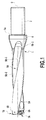
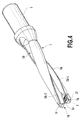
- An indexable drill shown in Fig. 1 to Fig. 6 includes a drill body 1 and two cutting inserts 7A and 7B for installation in the drill body 1.
- the drill body 1 is a substantially cylindrical member of the indexable drill which has an axis of rotation O.
- the drill body 1 includes a shank portion 3, a flange portion 4, a first chip discharging groove 5A and a second chip discharging groove 5B, and a central edge insert attachment seat 6A and an outer peripheral edge insert attachment seat 6B.
- the shank portion 3 is formed on a trailing end side of the axis of rotation O of the drill body 1 (on the right side of Fig. 1 ) so as to allow the drill body 1 to be removably installed in a machine tool such as a machining center.
- the shank portion 3 includes a surface 3f formed thereon parallel to the axis of rotation O.
- the flange portion 4 includes an end surface 4a provided adjacent to the shank 3 and which, when installed in a machine tool, comes into abutting contact with a spindle of the machine tool or an end surface of a holder.
- the first chip discharging groove 5A and the second chip discharging groove 5B are spirally formed so as to extend from a leading end surface 1f toward the trailing end side of the drill body 1 and to the middle of the flange portion 4.
- the first chip discharging groove 5A and the second chip discharging groove 5B are configured to discharge chips generated by cutting inserts 7A and 7B from the leading end surface 1f toward trailing end side of the drill body 1.
- the first chip discharging groove 5A and the second chip discharging groove 5B are rotationally symmetric with respect to the axis of rotation O of the drill body 1.
- first chip discharging groove 5A and the second chip discharging groove 5B are defined by first wall surfaces 5A-1 and 5B-1 facing in a drill rotating direction R shown in Fig. 3 and second wall surfaces 5A-2 and 5B-2 crossing the first wall surfaces 5A-1 and 5B-1 substantially at right angles and facing in a direction opposite to the tool rotating direction R, respectively.
- the central edge attachment seat 6A is recessed in a leading end portion of the first wall surface 5A-1 of the first chip discharging groove 5A so that the cutting insert 7A can be attached to the central edge attachment seat 6A.
- the outer peripheral edge attachment seat 6B is recessed in a leading end portion of the first wall surface SB-1 of the second chip discharging groove 5B so that the cutting insert 7B can be attached to the outer peripheral edge attachment seat 6B.
- the central edge attachment seat 6A allows the cutting insert 7A to be located close to the central axis O.
- the outer peripheral edge attachment seat 6B allows the cutting insert 7B to be located away from the central axis O.
- a tinned wall portion 1w that is thinner than a rotational-outward-direction-side wall portion of the drill body is present between the central edge attachment seat 6A and the second wall surface 5B-2 and between the outer peripheral edge attachment seat 6B and the second wall surface 5A-2, as shown in Fig. 3 and other figures.
- Two oil holes 9 are formed inside the drill body 1 so that one end of each of the oil holes 9 is open in the leading end surface 1f, while the other end is open in a trailing end surface of the shank 3.
- the oil holes 9 are provided to allow coolant to be injected from the leading end surface 1f toward.
- the cutting inserts 7A and 7B are attached to central edge attachment seat 6A and the outer peripheral edge attachment seat 6B, respectively, using clamp bolts BT.
- the cutting inserts 7A and 7B have the same structure and, in the present embodiment, are formed of a hard material selected from cemented carbide, cermet, ceramic, or the like.
- the cutting inserts 7A and 7B are of a positive type and are each formed like a flat plate with a parallelogrammic external shape.
- an upper surface of each cutting insert located opposite a seating surface forms a rake face, and a side surface thereof form a flank face.
- the flank face is provided with a flank angle of 11° according to the present embodiment.
- a chip breaker is formed on the rake face so as to rise from the rake face.
- Each of the cutting inserts 7A and 7B includes an attachment hole formed in a central portion thereof and penetrating the cutting insert from the rake face toward the seating surface.
- the cutting inserts 7A and 7B are further configured as follows. As shown in Fig. 2 , in the crossing portion between the rake face and the flank face, each short side portion of the substantial parallelogram forms a cutting edge 7a. Each long side portion of the substantial parallelogram forms a cutting edge 7b. Each corner portion of the substantial parallelogram which forms an acute angle forms a cutting edge 7c. If the cutting inserts 7A and 7B as shown in Fig. 2 are used for boring or the like, then in the cutting insert 7A (hereinafter also referred to as the central edge insert 7A), the cutting edges 7b and 7c contribute to cutting. In the cutting insert 7B (hereinafter also referred to as the outer peripheral edge insert 7B), the cutting edges 7a and 7b contribute to cutting. Furthermore, the outer peripheral edge insert 7B has a shorter cutting width than the central edge insert 7A.
- the drill body 1 is preferably formed of a material such as carbon steel, alloy steel, tool steel, or the like.
- the present embodiment adopts SKD11 (JIS ⁇ G4404-2006), a type of alloy tool steel included in tool steel.
- the drill body 1 as a whole is subjected to heat treating such as quenching and tempering so as to have a hardness of 40 to 60 HRC in terms of Rockwell hardness.
- the first chip discharging groove 5A and the second chip discharging groove 5B have not been formed or have been roughly processed.
- the first chip discharging groove 5A and the second chip discharging groove 5B are cut with a cutting tool such as an end mill.
- a cutting tool such as an end mill.
- the first chip discharging groove 5A and the second chip discharging groove 5B can each be finished to a desired shape by using a grinding agent to grind the wall surface thereof.
- the drill body 1 is desirably excellent in corrosion resistance and strength (high-temperature strength).
- stainless steel and heat-resistant steel are suitable as a material for forming the drill body 1.
- the rotating end mill When the first chip discharging groove 5A and the second chip discharging groove 5B are formed in the drill body 1 using a cutting tool such as an end mill, the rotating end mill preferably may be arranged so that the axis of rotation of the end mill is substantially orthogonal to the axis of rotation O of the drill body 1.
- the outer peripheral cutting edge of the end mill maintains its posture so as to lie along the first wall surface 5A-1 of the first chip discharging groove 5A and the first wall surface 5B-1 of the second chip discharging groove 5B. In this condition, the end mill is fed from the leading end side toward trailing end side of the drill body 1 to allow the first wall surfaces 5A-1 and 5B-1 to be cut.
- the end mill is fed from the leading end portion to trailing end portion of the drill body 1 with the outer peripheral cutting edge of the end mill maintaining its posture so as to lie along the second wall surfaces 5A-2 and 5B-2.
- the end mill is a radius end mill or a ball end mill.
- a crossing portion 5A-3 between the first wall surface 5A-1 and the second wall surface 5A-2 and a crossing portion 5B-3 between the first wall surface 5B-1 and the second wall surface 5B-2 form curved surfaces rounded so as to have a radius of curvature almost equal to the corner radius or ball radius of the end mill.
- first chip discharging groove 5A and the second chip discharging groove 5B are roughly processed before the drill body 1 is heat treated, no operation but finish cutting with the end mill is required as described above.
- no processing is carried out on the first chip discharging groove 5A and the second chip discharging groove 5B before the drill body 1 is thermally treated, cutting all the grooves at once with the end mill places an excessively heavy load on the end mill and the drill body 1.
- at least one rough cutting operation is performed before the final finish cutting is carried out.
- the wall surface of each groove having undergone the finish cutting may be subjected to cutting (what is called zero cut) using the same tool path as that in the finish cutting. This enables a further reduction in the surface roughness of the wall surface of each of the first chip discharging groove 5A and the second chip discharging groove 5B.
- the central edge attachment seat 6A and the outer peripheral edge attachment seat 6B are processed at the leading end portion of the first wall surface 5A-1 of the first chip discharging groove 5A and at the leading end portion of the first wall surface 5B-1 of the second chip discharging groove 5B.
- the outer peripheral surface of the drill body 1 is turned so as to have a desired outer diameter dimension. The turning may leave burrs on the first and second wall surfaces of the first chip discharging groove 5A and the second chip discharging groove 5B.
- the drill body 1 includes the thinned wall portion 1w at the leading end portion 1w.
- the toughness of the drill body 1 can be restrained from being degraded, by adjusting the hardness of the thinned wall portion 1w to 40 to 60 HRC in Rockwell hardness.
- the thinned wall portion 1w can be restrained from being broken. This enables the life of the drill body 1 to be extended.
- the first and second wall surfaces of the first chip discharging groove 5A and the second chip discharging groove 5B are smoothed so as to have a surface roughness of at most 0.5 ⁇ m (JIS ⁇ B0601 : 2001) in terms of arithmetic average roughness Ra.
- the present embodiment adopts SKD11 as a material for the drill body 11 and adjusts the hardness of SKD11 from 40 to 60 HRC.
- the wall surfaces thus have a surface roughness of at most 0.5 ⁇ m in terms of arithmetic average roughness Ra.
- the wall surfaces of the first chip discharging groove 5A and the second chip discharging groove 5B partly or entirely have a surface roughness of at most 0.5 ⁇ in terms of Ra, the wall surfaces can be made smooth enough to reduce friction caused by the contact of the wall surfaces with chips. This allows chips to be smoothly discharged.
- Ra is desirably greater than 0.1 ⁇ m.
- first wall surfaces 5A-1 and 5B-1 and the second wall surfaces 5A-2 and 5B-2 are desirably shaped using a cutting tool such as above-described endmill so as to leave a slight removal stock to be removed by grinding.
- the adopted grinding with the grinding tool may be known grinding such as grinding with a brush mixed with a grinding agent, polishing, barrel grinding, buffing, or lapping.
- the grinding agent adopted may be a known grinding agent, for example, chromium oxide, iron oxide, diamond, silicon carbide, aluminum oxide, or cubic boron nitride.
- shot blasting may be used in which a shot blast material is allowed to collide against at least the wall surfaces of the first chip discharging groove 5A and the second chip discharging groove 5B. In this case, when the shot blast material is particles of diameter at most about 100 ⁇ m, the shot blasting is effective for improving the surface roughness of the wall surfaces.
- the shot blasting increases the hardness of the wall surfaces and also improves wear resistance.
- the grinding agent When the grinding agent is used to grind the first and second wall surfaces of the first chip discharging groove 5A and the second chip discharging groove 5B and the crossing portion between these wall surfaces, protruding portions of the first and second wall surfaces are preferentially grind. This allows the first and second surfaces of the first chip discharging groove 5A and the second chip discharging groove 5B to be smoothed so as to have a surface roughness Ra of at most 0.5 ⁇ m.
- the indexable drill during boring, coolant is continuously supplied to a cutting site through the oil holes 9.
- the coolant flows together with chips from the leading end toward trailing end of the drill through the first chip discharging groove 5A and the second chip discharging groove 5B.
- the chips are forcibly swept way toward the trailing end of the drill body 1.
- chips generated by the central edge insert 7A come into contact with the first wall surface 5A-1 or second wall surface 5A-2 of the first chip discharging groove 5A.
- Chips generated by the outer peripheral edge insert 7B come into contact with the first wall surface 5B-1 or second wall surface 5B-2 of the second chip discharging groove 5B.
- the indexable drill since the first wall surface 5A-1 and second wall surface 5A-2 of the first chip discharging groove 5A and the first wall surface 5B-1 and second wall surface 5B-2 of the second chip discharging groove 5B are smoothed, the flow of the chips is prevented from being hampered, allowing the chips to be smoothly discharged toward the trailing end. At this time, since the first chip discharging groove 5A and the second chip discharging groove 5B are spirally formed, what is called pumping action urges the chips to be discharged.
- a coat with a higher hardness than the wall surfaces can be formed on the smoothed wall surfaces of the first chip discharging groove 5A and the second chip discharging groove 5B.
- the coat may be electroless nickel plating, hard chromium plating, or the like.
- the hard chromium plating provides a hard coat and thus high wear resistance. In these types of plating, the surface roughness of the coat surface is almost equivalent to that of the wall surface of the groove. Thus, the coat is prevented from hampering the flow of the hips, allowing maintenance of the effect of urging the flow of the chips through the grooves.
- the wall surfaces defining the first chip discharging groove 5A and the second chip discharging groove 5B are entirely smoothed.
- parts of the wall surfaces which are likely to be worn may be exclusively smoothed.
Landscapes
- Engineering & Computer Science (AREA)
- Mechanical Engineering (AREA)
- Drilling Tools (AREA)
Applications Claiming Priority (2)
| Application Number | Priority Date | Filing Date | Title |
|---|---|---|---|
| JP2009132907 | 2009-06-02 | ||
| PCT/JP2010/059314 WO2010140606A1 (fr) | 2009-06-02 | 2010-06-02 | Foret à bord de coupe pouvant être remplacé et corps principal de foret |
Publications (1)
| Publication Number | Publication Date |
|---|---|
| EP2439009A1 true EP2439009A1 (fr) | 2012-04-11 |
Family
ID=43297739
Family Applications (1)
| Application Number | Title | Priority Date | Filing Date |
|---|---|---|---|
| EP10783388A Withdrawn EP2439009A1 (fr) | 2009-06-02 | 2010-06-02 | Foret à bord de coupe pouvant être remplacé et corps principal de foret |
Country Status (9)
| Country | Link |
|---|---|
| US (1) | US8393831B2 (fr) |
| EP (1) | EP2439009A1 (fr) |
| JP (1) | JPWO2010140606A1 (fr) |
| KR (1) | KR20120023659A (fr) |
| CN (1) | CN102802850A (fr) |
| BR (1) | BRPI1011093A2 (fr) |
| CA (1) | CA2764129C (fr) |
| RU (1) | RU2488464C1 (fr) |
| WO (1) | WO2010140606A1 (fr) |
Cited By (1)
| Publication number | Priority date | Publication date | Assignee | Title |
|---|---|---|---|---|
| EP3795282A4 (fr) * | 2018-05-16 | 2022-01-19 | Sumitomo Electric Hardmetal Corp. | Plaquette de coupe pour foret, et foret |
Families Citing this family (20)
| Publication number | Priority date | Publication date | Assignee | Title |
|---|---|---|---|---|
| EP2435202B1 (fr) * | 2009-05-26 | 2013-08-14 | GKN Aerospace Sweden AB | Support pour outil de coupe, outil de coupe et plaquette de coupe |
| JPWO2010137701A1 (ja) * | 2009-05-29 | 2012-11-15 | 株式会社タンガロイ | 刃先交換式ドリルおよびドリル本体 |
| US20110318129A1 (en) * | 2010-06-24 | 2011-12-29 | Piper Arthur A | Auger Bit |
| CN103796781B (zh) * | 2011-09-16 | 2017-07-21 | Osg株式会社 | 可转位式钻头的钻头主体 |
| JP5823840B2 (ja) * | 2011-11-30 | 2015-11-25 | 富士重工業株式会社 | ドリルおよび切削加工物の製造方法 |
| JP5979054B2 (ja) * | 2013-03-25 | 2016-08-24 | 三菱マテリアル株式会社 | ドリル用インサートおよび刃先交換式ドリル |
| KR101537718B1 (ko) | 2014-04-23 | 2015-07-20 | 한국야금 주식회사 | 부분적으로 제거된 피막이 형성된 절삭공구 |
| US11376675B2 (en) | 2014-04-23 | 2022-07-05 | Korloy Inc. | Cutting tool having partially-removed film formed thereon |
| EP3034214A1 (fr) * | 2014-12-19 | 2016-06-22 | Pramet Tools, S.R.O. | Foret et insert pour foret avec des saillies de brise-copeaux |
| GB2556559B (en) * | 2015-07-27 | 2021-09-15 | Karsten Mfg Corp | Golf club heads with variable face geometry and material properties |
| US20180243841A1 (en) * | 2015-09-09 | 2018-08-30 | Mitsubishi Materials Corporation | Drill |
| EP3401043B1 (fr) * | 2017-05-11 | 2020-03-25 | Sandvik Intellectual Property AB | Corps de trépan et trépan |
| EP3401042B1 (fr) * | 2017-05-11 | 2020-07-22 | Sandvik Intellectual Property AB | Corps de foret et foret |
| RU193800U1 (ru) * | 2017-09-11 | 2019-11-15 | Общество с ограниченной ответственностью "Промышленная компания МИОН" | Сверло укороченное повышенной жесткости с смп для обработки отверстий в рельсах |
| JP6503523B1 (ja) * | 2019-01-25 | 2019-04-17 | 古河ロックドリル株式会社 | ドリルツールおよびその製造方法 |
| JP6737932B1 (ja) * | 2019-03-05 | 2020-08-12 | 住友化学株式会社 | 切削加工フィルムの製造方法 |
| CN112492756B (zh) * | 2020-11-25 | 2022-06-07 | 赣州市硕祺电子科技有限公司 | 一种电气工程用针对pcb板的定位孔快速除胶装置 |
| CN113427207A (zh) * | 2021-06-09 | 2021-09-24 | 东台升华工具有限公司 | 一种铝用直槽钻头排屑槽后处理工艺 |
| CN114453637B (zh) * | 2021-12-30 | 2024-10-22 | 常州英曼斯工具有限公司 | 一种硬质合金可转位的锥度钻及其加工方法 |
| CN114535665B (zh) * | 2022-04-25 | 2022-09-16 | 成都飞机工业(集团)有限责任公司 | 一种弱刚性构件的制孔方法 |
Family Cites Families (20)
| Publication number | Priority date | Publication date | Assignee | Title |
|---|---|---|---|---|
| JPS63245310A (ja) * | 1987-03-28 | 1988-10-12 | Mitsubishi Metal Corp | ドリル |
| JPH04256522A (ja) | 1991-02-01 | 1992-09-11 | Kanai Hiroyuki | ドリル材の製造方法 |
| JP2757744B2 (ja) | 1992-07-31 | 1998-05-25 | 三菱マテリアル株式会社 | スローアウェイ式穴明け工具およびスローアウェイチップ |
| DE9215855U1 (de) * | 1992-11-21 | 1994-03-24 | Widia GmbH, 45145 Essen | Schneideinsatz |
| SE501515C2 (sv) * | 1993-03-03 | 1995-03-06 | Sandvik Ab | Spiralborr med förbättrad böjstyvhet |
| CN1076238C (zh) | 1996-02-29 | 2001-12-19 | 彗星罗伯特布朗宁精密刀具有限公司 | 用于机床的钻孔工具及其制造方法 |
| JPH1190715A (ja) * | 1997-09-12 | 1999-04-06 | Toshiba Tungaloy Co Ltd | スローアウェイ式ドリル |
| JP2001191205A (ja) * | 2000-01-06 | 2001-07-17 | Mitsubishi Materials Corp | スローアウェイ式穴明け工具 |
| JP2001341021A (ja) * | 2000-03-30 | 2001-12-11 | Hitachi Tool Engineering Ltd | ツイストドリル |
| DE10021879A1 (de) * | 2000-05-05 | 2001-11-08 | Komet Stahlhalter Werkzeuge | Vollbohrer für Werkzeugmaschinen |
| JP2002301610A (ja) * | 2001-04-06 | 2002-10-15 | Hitachi Tool Engineering Ltd | 深穴用ドリル |
| IL145574A0 (en) * | 2001-09-24 | 2002-06-30 | Iscar Ltd | Cutting tool and cutting insert therefor |
| SE525241C2 (sv) * | 2002-05-29 | 2005-01-11 | Sandvik Ab | Borrverktygsats, borrverktyg samt indexerbart borrskär härför |
| JP2004074371A (ja) * | 2002-08-21 | 2004-03-11 | Toyo Corp | バリ取り用工具 |
| JP3985713B2 (ja) * | 2003-03-31 | 2007-10-03 | 三菱マテリアル株式会社 | ドリル |
| JP2005022064A (ja) * | 2003-07-03 | 2005-01-27 | Tungaloy Corp | 被覆穴あけ工具 |
| SE527684C2 (sv) * | 2004-11-10 | 2006-05-09 | Sandvik Intellectual Property | Skärande verktyg för metallbearbetning samt metod vid tillverkning av skärande verktyg |
| JP2006167848A (ja) * | 2004-12-15 | 2006-06-29 | Hitachi Tool Engineering Ltd | スパイラル貫通孔付き深穴用ドリル |
| JP4554383B2 (ja) * | 2005-01-26 | 2010-09-29 | 株式会社タンガロイ | スローアウェイ式ドリル |
| JP2006326752A (ja) | 2005-05-26 | 2006-12-07 | Mitsubishi Materials Corp | ドリル |
-
2010
- 2010-06-02 EP EP10783388A patent/EP2439009A1/fr not_active Withdrawn
- 2010-06-02 JP JP2011518462A patent/JPWO2010140606A1/ja active Pending
- 2010-06-02 CN CN2010800244769A patent/CN102802850A/zh active Pending
- 2010-06-02 KR KR1020117027044A patent/KR20120023659A/ko not_active Abandoned
- 2010-06-02 RU RU2011149091/02A patent/RU2488464C1/ru not_active IP Right Cessation
- 2010-06-02 CA CA2764129A patent/CA2764129C/fr not_active Expired - Fee Related
- 2010-06-02 BR BRPI1011093A patent/BRPI1011093A2/pt not_active IP Right Cessation
- 2010-06-02 WO PCT/JP2010/059314 patent/WO2010140606A1/fr not_active Ceased
-
2011
- 2011-11-18 US US13/300,190 patent/US8393831B2/en active Active
Non-Patent Citations (1)
| Title |
|---|
| See references of WO2010140606A1 * |
Cited By (2)
| Publication number | Priority date | Publication date | Assignee | Title |
|---|---|---|---|---|
| EP3795282A4 (fr) * | 2018-05-16 | 2022-01-19 | Sumitomo Electric Hardmetal Corp. | Plaquette de coupe pour foret, et foret |
| US11446742B2 (en) | 2018-05-16 | 2022-09-20 | Sumitomo Electric Hardmetal Corp. | Cutting insert for drill, and drill |
Also Published As
| Publication number | Publication date |
|---|---|
| CN102802850A (zh) | 2012-11-28 |
| CA2764129A1 (fr) | 2010-12-09 |
| JPWO2010140606A1 (ja) | 2012-11-22 |
| WO2010140606A1 (fr) | 2010-12-09 |
| RU2488464C1 (ru) | 2013-07-27 |
| US8393831B2 (en) | 2013-03-12 |
| KR20120023659A (ko) | 2012-03-13 |
| US20120063857A1 (en) | 2012-03-15 |
| CA2764129C (fr) | 2013-10-15 |
| BRPI1011093A2 (pt) | 2018-02-06 |
Similar Documents
| Publication | Publication Date | Title |
|---|---|---|
| CA2764129C (fr) | Foret indexable et corps de foret | |
| US9446460B2 (en) | Cutting insert for high feed face milling | |
| US7625161B1 (en) | Rotary cutting tool assembly and cutting insert and tool shank therefor | |
| CN102271847B (zh) | 用于去屑加工的旋转刀具及用于该刀具的切削刀片 | |
| JP3899309B2 (ja) | 表面の精密加工のための工具 | |
| RU2409454C2 (ru) | Концевая фреза для орбитального фрезерования | |
| JP3720010B2 (ja) | 深穴加工用ドリル | |
| KR101526642B1 (ko) | 멀티엣지 드릴 | |
| JPWO2017051471A1 (ja) | 切削インサート、及び刃先交換式回転切削工具 | |
| JP2003300110A (ja) | ドリルおよびその製造方法 | |
| CN210552206U (zh) | 一种切削刀具及其刀头结构 | |
| CA2760600A1 (fr) | Plaquette extra-dure | |
| SE1050877A1 (sv) | Skär med radieparti, verktyg och anordning för fräsning | |
| AU2009291529A1 (en) | Adjustable indexable drill and modular system and holder | |
| US10850335B2 (en) | Cutting insert and cutting edge-interchangeable rotary cutting tool | |
| JP2010094748A (ja) | 切削工具 | |
| EP2756901B1 (fr) | Corps de foret de foret amovible | |
| JP2023521019A (ja) | 四辺形状面部分を形成するように連続的な大きな溝および不連続的な小さな溝が交差する回転切削工具 | |
| WO2022181123A1 (fr) | Insert de coupe et outil de coupe à bord de coupe remplaçable | |
| JP2017080864A (ja) | 刃先交換式リーマおよびリーマ用インサート | |
| JP5953173B2 (ja) | 切削工具 | |
| US20230128504A1 (en) | Machining process with minimized burr formation | |
| RU2401724C2 (ru) | Машинная развертка | |
| EP3505284B1 (fr) | Plaquette de coupe et outil de coupe rotatif amovible | |
| JPH11216608A (ja) | ボ−ルエンドミル |
Legal Events
| Date | Code | Title | Description |
|---|---|---|---|
| PUAI | Public reference made under article 153(3) epc to a published international application that has entered the european phase |
Free format text: ORIGINAL CODE: 0009012 |
|
| 17P | Request for examination filed |
Effective date: 20111206 |
|
| AK | Designated contracting states |
Kind code of ref document: A1 Designated state(s): AL AT BE BG CH CY CZ DE DK EE ES FI FR GB GR HR HU IE IS IT LI LT LU LV MC MK MT NL NO PL PT RO SE SI SK SM TR |
|
| DAX | Request for extension of the european patent (deleted) | ||
| STAA | Information on the status of an ep patent application or granted ep patent |
Free format text: STATUS: THE APPLICATION HAS BEEN WITHDRAWN |
|
| 18W | Application withdrawn |
Effective date: 20130916 |