EP2439055A2 - Funktionales Element zur Befestigung an einer Kunststoffkomponente und Komponentenanordnung - Google Patents
Funktionales Element zur Befestigung an einer Kunststoffkomponente und Komponentenanordnung Download PDFInfo
- Publication number
- EP2439055A2 EP2439055A2 EP11008061A EP11008061A EP2439055A2 EP 2439055 A2 EP2439055 A2 EP 2439055A2 EP 11008061 A EP11008061 A EP 11008061A EP 11008061 A EP11008061 A EP 11008061A EP 2439055 A2 EP2439055 A2 EP 2439055A2
- Authority
- EP
- European Patent Office
- Prior art keywords
- adhesive
- functional element
- component
- attachment surface
- ring
- Prior art date
- Legal status (The legal status is an assumption and is not a legal conclusion. Google has not performed a legal analysis and makes no representation as to the accuracy of the status listed.)
- Granted
Links
Images




Classifications
-
- F—MECHANICAL ENGINEERING; LIGHTING; HEATING; WEAPONS; BLASTING
- F16—ENGINEERING ELEMENTS AND UNITS; GENERAL MEASURES FOR PRODUCING AND MAINTAINING EFFECTIVE FUNCTIONING OF MACHINES OR INSTALLATIONS; THERMAL INSULATION IN GENERAL
- F16B—DEVICES FOR FASTENING OR SECURING CONSTRUCTIONAL ELEMENTS OR MACHINE PARTS TOGETHER, e.g. NAILS, BOLTS, CIRCLIPS, CLAMPS, CLIPS OR WEDGES; JOINTS OR JOINTING
- F16B39/00—Locking of screws, bolts or nuts
- F16B39/02—Locking of screws, bolts or nuts in which the locking takes place after screwing down
-
- B—PERFORMING OPERATIONS; TRANSPORTING
- B29—WORKING OF PLASTICS; WORKING OF SUBSTANCES IN A PLASTIC STATE IN GENERAL
- B29C—SHAPING OR JOINING OF PLASTICS; SHAPING OF MATERIAL IN A PLASTIC STATE, NOT OTHERWISE PROVIDED FOR; AFTER-TREATMENT OF THE SHAPED PRODUCTS, e.g. REPAIRING
- B29C65/00—Joining or sealing of preformed parts, e.g. welding of plastics materials; Apparatus therefor
- B29C65/48—Joining or sealing of preformed parts, e.g. welding of plastics materials; Apparatus therefor using adhesives, i.e. using supplementary joining material; solvent bonding
- B29C65/4805—Joining or sealing of preformed parts, e.g. welding of plastics materials; Apparatus therefor using adhesives, i.e. using supplementary joining material; solvent bonding characterised by the type of adhesives
- B29C65/483—Reactive adhesives, e.g. chemically curing adhesives
- B29C65/485—Multi-component adhesives, i.e. chemically curing as a result of the mixing of said multi-components
-
- B—PERFORMING OPERATIONS; TRANSPORTING
- B29—WORKING OF PLASTICS; WORKING OF SUBSTANCES IN A PLASTIC STATE IN GENERAL
- B29C—SHAPING OR JOINING OF PLASTICS; SHAPING OF MATERIAL IN A PLASTIC STATE, NOT OTHERWISE PROVIDED FOR; AFTER-TREATMENT OF THE SHAPED PRODUCTS, e.g. REPAIRING
- B29C65/00—Joining or sealing of preformed parts, e.g. welding of plastics materials; Apparatus therefor
- B29C65/48—Joining or sealing of preformed parts, e.g. welding of plastics materials; Apparatus therefor using adhesives, i.e. using supplementary joining material; solvent bonding
- B29C65/4865—Joining or sealing of preformed parts, e.g. welding of plastics materials; Apparatus therefor using adhesives, i.e. using supplementary joining material; solvent bonding containing additives
- B29C65/487—Joining or sealing of preformed parts, e.g. welding of plastics materials; Apparatus therefor using adhesives, i.e. using supplementary joining material; solvent bonding containing additives characterised by their shape, e.g. being fibres or being spherical
- B29C65/4875—Joining or sealing of preformed parts, e.g. welding of plastics materials; Apparatus therefor using adhesives, i.e. using supplementary joining material; solvent bonding containing additives characterised by their shape, e.g. being fibres or being spherical being spherical, e.g. particles or powders
-
- B—PERFORMING OPERATIONS; TRANSPORTING
- B29—WORKING OF PLASTICS; WORKING OF SUBSTANCES IN A PLASTIC STATE IN GENERAL
- B29C—SHAPING OR JOINING OF PLASTICS; SHAPING OF MATERIAL IN A PLASTIC STATE, NOT OTHERWISE PROVIDED FOR; AFTER-TREATMENT OF THE SHAPED PRODUCTS, e.g. REPAIRING
- B29C65/00—Joining or sealing of preformed parts, e.g. welding of plastics materials; Apparatus therefor
- B29C65/48—Joining or sealing of preformed parts, e.g. welding of plastics materials; Apparatus therefor using adhesives, i.e. using supplementary joining material; solvent bonding
- B29C65/50—Joining or sealing of preformed parts, e.g. welding of plastics materials; Apparatus therefor using adhesives, i.e. using supplementary joining material; solvent bonding using adhesive tape, e.g. thermoplastic tape; using threads or the like
- B29C65/5057—Joining or sealing of preformed parts, e.g. welding of plastics materials; Apparatus therefor using adhesives, i.e. using supplementary joining material; solvent bonding using adhesive tape, e.g. thermoplastic tape; using threads or the like positioned between the surfaces to be joined
-
- B—PERFORMING OPERATIONS; TRANSPORTING
- B29—WORKING OF PLASTICS; WORKING OF SUBSTANCES IN A PLASTIC STATE IN GENERAL
- B29C—SHAPING OR JOINING OF PLASTICS; SHAPING OF MATERIAL IN A PLASTIC STATE, NOT OTHERWISE PROVIDED FOR; AFTER-TREATMENT OF THE SHAPED PRODUCTS, e.g. REPAIRING
- B29C65/00—Joining or sealing of preformed parts, e.g. welding of plastics materials; Apparatus therefor
- B29C65/78—Means for handling the parts to be joined, e.g. for making containers or hollow articles, e.g. means for handling sheets, plates, web-like materials, tubular articles, hollow articles or elements to be joined therewith; Means for discharging the joined articles from the joining apparatus
- B29C65/7802—Positioning the parts to be joined, e.g. aligning, indexing or centring
- B29C65/7805—Positioning the parts to be joined, e.g. aligning, indexing or centring the parts to be joined comprising positioning features
- B29C65/7808—Positioning the parts to be joined, e.g. aligning, indexing or centring the parts to be joined comprising positioning features in the form of holes or slots
- B29C65/7811—Positioning the parts to be joined, e.g. aligning, indexing or centring the parts to be joined comprising positioning features in the form of holes or slots for centring purposes
-
- B—PERFORMING OPERATIONS; TRANSPORTING
- B29—WORKING OF PLASTICS; WORKING OF SUBSTANCES IN A PLASTIC STATE IN GENERAL
- B29C—SHAPING OR JOINING OF PLASTICS; SHAPING OF MATERIAL IN A PLASTIC STATE, NOT OTHERWISE PROVIDED FOR; AFTER-TREATMENT OF THE SHAPED PRODUCTS, e.g. REPAIRING
- B29C65/00—Joining or sealing of preformed parts, e.g. welding of plastics materials; Apparatus therefor
- B29C65/78—Means for handling the parts to be joined, e.g. for making containers or hollow articles, e.g. means for handling sheets, plates, web-like materials, tubular articles, hollow articles or elements to be joined therewith; Means for discharging the joined articles from the joining apparatus
- B29C65/7802—Positioning the parts to be joined, e.g. aligning, indexing or centring
- B29C65/7805—Positioning the parts to be joined, e.g. aligning, indexing or centring the parts to be joined comprising positioning features
- B29C65/7814—Positioning the parts to be joined, e.g. aligning, indexing or centring the parts to be joined comprising positioning features in the form of inter-cooperating positioning features, e.g. tenons and mortises
-
- B—PERFORMING OPERATIONS; TRANSPORTING
- B29—WORKING OF PLASTICS; WORKING OF SUBSTANCES IN A PLASTIC STATE IN GENERAL
- B29C—SHAPING OR JOINING OF PLASTICS; SHAPING OF MATERIAL IN A PLASTIC STATE, NOT OTHERWISE PROVIDED FOR; AFTER-TREATMENT OF THE SHAPED PRODUCTS, e.g. REPAIRING
- B29C65/00—Joining or sealing of preformed parts, e.g. welding of plastics materials; Apparatus therefor
- B29C65/78—Means for handling the parts to be joined, e.g. for making containers or hollow articles, e.g. means for handling sheets, plates, web-like materials, tubular articles, hollow articles or elements to be joined therewith; Means for discharging the joined articles from the joining apparatus
- B29C65/7841—Holding or clamping means for handling purposes
-
- B—PERFORMING OPERATIONS; TRANSPORTING
- B29—WORKING OF PLASTICS; WORKING OF SUBSTANCES IN A PLASTIC STATE IN GENERAL
- B29C—SHAPING OR JOINING OF PLASTICS; SHAPING OF MATERIAL IN A PLASTIC STATE, NOT OTHERWISE PROVIDED FOR; AFTER-TREATMENT OF THE SHAPED PRODUCTS, e.g. REPAIRING
- B29C66/00—General aspects of processes or apparatus for joining preformed parts
- B29C66/01—General aspects dealing with the joint area or with the area to be joined
- B29C66/05—Particular design of joint configurations
- B29C66/10—Particular design of joint configurations particular design of the joint cross-sections
- B29C66/12—Joint cross-sections combining only two joint-segments; Tongue and groove joints; Tenon and mortise joints; Stepped joint cross-sections
- B29C66/122—Joint cross-sections combining only two joint-segments, i.e. one of the parts to be joined comprising only two joint-segments in the joint cross-section
- B29C66/1222—Joint cross-sections combining only two joint-segments, i.e. one of the parts to be joined comprising only two joint-segments in the joint cross-section comprising at least a lapped joint-segment
-
- B—PERFORMING OPERATIONS; TRANSPORTING
- B29—WORKING OF PLASTICS; WORKING OF SUBSTANCES IN A PLASTIC STATE IN GENERAL
- B29C—SHAPING OR JOINING OF PLASTICS; SHAPING OF MATERIAL IN A PLASTIC STATE, NOT OTHERWISE PROVIDED FOR; AFTER-TREATMENT OF THE SHAPED PRODUCTS, e.g. REPAIRING
- B29C66/00—General aspects of processes or apparatus for joining preformed parts
- B29C66/01—General aspects dealing with the joint area or with the area to be joined
- B29C66/05—Particular design of joint configurations
- B29C66/10—Particular design of joint configurations particular design of the joint cross-sections
- B29C66/12—Joint cross-sections combining only two joint-segments; Tongue and groove joints; Tenon and mortise joints; Stepped joint cross-sections
- B29C66/122—Joint cross-sections combining only two joint-segments, i.e. one of the parts to be joined comprising only two joint-segments in the joint cross-section
- B29C66/1224—Joint cross-sections combining only two joint-segments, i.e. one of the parts to be joined comprising only two joint-segments in the joint cross-section comprising at least a butt joint-segment
-
- B—PERFORMING OPERATIONS; TRANSPORTING
- B29—WORKING OF PLASTICS; WORKING OF SUBSTANCES IN A PLASTIC STATE IN GENERAL
- B29C—SHAPING OR JOINING OF PLASTICS; SHAPING OF MATERIAL IN A PLASTIC STATE, NOT OTHERWISE PROVIDED FOR; AFTER-TREATMENT OF THE SHAPED PRODUCTS, e.g. REPAIRING
- B29C66/00—General aspects of processes or apparatus for joining preformed parts
- B29C66/01—General aspects dealing with the joint area or with the area to be joined
- B29C66/05—Particular design of joint configurations
- B29C66/10—Particular design of joint configurations particular design of the joint cross-sections
- B29C66/13—Single flanged joints; Fin-type joints; Single hem joints; Edge joints; Interpenetrating fingered joints; Other specific particular designs of joint cross-sections not provided for in groups B29C66/11 - B29C66/12
- B29C66/131—Single flanged joints, i.e. one of the parts to be joined being rigid and flanged in the joint area
-
- B—PERFORMING OPERATIONS; TRANSPORTING
- B29—WORKING OF PLASTICS; WORKING OF SUBSTANCES IN A PLASTIC STATE IN GENERAL
- B29C—SHAPING OR JOINING OF PLASTICS; SHAPING OF MATERIAL IN A PLASTIC STATE, NOT OTHERWISE PROVIDED FOR; AFTER-TREATMENT OF THE SHAPED PRODUCTS, e.g. REPAIRING
- B29C66/00—General aspects of processes or apparatus for joining preformed parts
- B29C66/01—General aspects dealing with the joint area or with the area to be joined
- B29C66/32—Measures for keeping the burr form under control; Avoiding burr formation; Shaping the burr
- B29C66/322—Providing cavities in the joined article to collect the burr
-
- B—PERFORMING OPERATIONS; TRANSPORTING
- B29—WORKING OF PLASTICS; WORKING OF SUBSTANCES IN A PLASTIC STATE IN GENERAL
- B29C—SHAPING OR JOINING OF PLASTICS; SHAPING OF MATERIAL IN A PLASTIC STATE, NOT OTHERWISE PROVIDED FOR; AFTER-TREATMENT OF THE SHAPED PRODUCTS, e.g. REPAIRING
- B29C66/00—General aspects of processes or apparatus for joining preformed parts
- B29C66/40—General aspects of joining substantially flat articles, e.g. plates, sheets or web-like materials; Making flat seams in tubular or hollow articles; Joining single elements to substantially flat surfaces
- B29C66/47—Joining single elements to sheets, plates or other substantially flat surfaces
- B29C66/474—Joining single elements to sheets, plates or other substantially flat surfaces said single elements being substantially non-flat
-
- B—PERFORMING OPERATIONS; TRANSPORTING
- B29—WORKING OF PLASTICS; WORKING OF SUBSTANCES IN A PLASTIC STATE IN GENERAL
- B29C—SHAPING OR JOINING OF PLASTICS; SHAPING OF MATERIAL IN A PLASTIC STATE, NOT OTHERWISE PROVIDED FOR; AFTER-TREATMENT OF THE SHAPED PRODUCTS, e.g. REPAIRING
- B29C66/00—General aspects of processes or apparatus for joining preformed parts
- B29C66/70—General aspects of processes or apparatus for joining preformed parts characterised by the composition, physical properties or the structure of the material of the parts to be joined; Joining with non-plastics material
- B29C66/74—Joining plastics material to non-plastics material
- B29C66/742—Joining plastics material to non-plastics material to metals or their alloys
-
- B—PERFORMING OPERATIONS; TRANSPORTING
- B29—WORKING OF PLASTICS; WORKING OF SUBSTANCES IN A PLASTIC STATE IN GENERAL
- B29C—SHAPING OR JOINING OF PLASTICS; SHAPING OF MATERIAL IN A PLASTIC STATE, NOT OTHERWISE PROVIDED FOR; AFTER-TREATMENT OF THE SHAPED PRODUCTS, e.g. REPAIRING
- B29C66/00—General aspects of processes or apparatus for joining preformed parts
- B29C66/80—General aspects of machine operations or constructions and parts thereof
- B29C66/83—General aspects of machine operations or constructions and parts thereof characterised by the movement of the joining or pressing tools
- B29C66/832—Reciprocating joining or pressing tools
- B29C66/8322—Joining or pressing tools reciprocating along one axis
-
- F—MECHANICAL ENGINEERING; LIGHTING; HEATING; WEAPONS; BLASTING
- F16—ENGINEERING ELEMENTS AND UNITS; GENERAL MEASURES FOR PRODUCING AND MAINTAINING EFFECTIVE FUNCTIONING OF MACHINES OR INSTALLATIONS; THERMAL INSULATION IN GENERAL
- F16B—DEVICES FOR FASTENING OR SECURING CONSTRUCTIONAL ELEMENTS OR MACHINE PARTS TOGETHER, e.g. NAILS, BOLTS, CIRCLIPS, CLAMPS, CLIPS OR WEDGES; JOINTS OR JOINTING
- F16B11/00—Connecting constructional elements or machine parts by sticking or pressing them together, e.g. cold pressure welding
- F16B11/006—Connecting constructional elements or machine parts by sticking or pressing them together, e.g. cold pressure welding by gluing
-
- F—MECHANICAL ENGINEERING; LIGHTING; HEATING; WEAPONS; BLASTING
- F16—ENGINEERING ELEMENTS AND UNITS; GENERAL MEASURES FOR PRODUCING AND MAINTAINING EFFECTIVE FUNCTIONING OF MACHINES OR INSTALLATIONS; THERMAL INSULATION IN GENERAL
- F16B—DEVICES FOR FASTENING OR SECURING CONSTRUCTIONAL ELEMENTS OR MACHINE PARTS TOGETHER, e.g. NAILS, BOLTS, CIRCLIPS, CLAMPS, CLIPS OR WEDGES; JOINTS OR JOINTING
- F16B37/00—Nuts or like thread-engaging members
- F16B37/04—Devices for fastening nuts to surfaces, e.g. sheets, plates
- F16B37/06—Devices for fastening nuts to surfaces, e.g. sheets, plates by means of welding or riveting
- F16B37/062—Devices for fastening nuts to surfaces, e.g. sheets, plates by means of welding or riveting by means of riveting
- F16B37/065—Devices for fastening nuts to surfaces, e.g. sheets, plates by means of welding or riveting by means of riveting by deforming the material of the nut
-
- F—MECHANICAL ENGINEERING; LIGHTING; HEATING; WEAPONS; BLASTING
- F16—ENGINEERING ELEMENTS AND UNITS; GENERAL MEASURES FOR PRODUCING AND MAINTAINING EFFECTIVE FUNCTIONING OF MACHINES OR INSTALLATIONS; THERMAL INSULATION IN GENERAL
- F16B—DEVICES FOR FASTENING OR SECURING CONSTRUCTIONAL ELEMENTS OR MACHINE PARTS TOGETHER, e.g. NAILS, BOLTS, CIRCLIPS, CLAMPS, CLIPS OR WEDGES; JOINTS OR JOINTING
- F16B37/00—Nuts or like thread-engaging members
- F16B37/04—Devices for fastening nuts to surfaces, e.g. sheets, plates
- F16B37/06—Devices for fastening nuts to surfaces, e.g. sheets, plates by means of welding or riveting
- F16B37/062—Devices for fastening nuts to surfaces, e.g. sheets, plates by means of welding or riveting by means of riveting
- F16B37/068—Devices for fastening nuts to surfaces, e.g. sheets, plates by means of welding or riveting by means of riveting by deforming the material of the support, e.g. the sheet or plate
-
- B—PERFORMING OPERATIONS; TRANSPORTING
- B29—WORKING OF PLASTICS; WORKING OF SUBSTANCES IN A PLASTIC STATE IN GENERAL
- B29C—SHAPING OR JOINING OF PLASTICS; SHAPING OF MATERIAL IN A PLASTIC STATE, NOT OTHERWISE PROVIDED FOR; AFTER-TREATMENT OF THE SHAPED PRODUCTS, e.g. REPAIRING
- B29C65/00—Joining or sealing of preformed parts, e.g. welding of plastics materials; Apparatus therefor
- B29C65/48—Joining or sealing of preformed parts, e.g. welding of plastics materials; Apparatus therefor using adhesives, i.e. using supplementary joining material; solvent bonding
- B29C65/4805—Joining or sealing of preformed parts, e.g. welding of plastics materials; Apparatus therefor using adhesives, i.e. using supplementary joining material; solvent bonding characterised by the type of adhesives
- B29C65/481—Non-reactive adhesives, e.g. physically hardening adhesives
- B29C65/4825—Pressure sensitive adhesives
-
- B—PERFORMING OPERATIONS; TRANSPORTING
- B29—WORKING OF PLASTICS; WORKING OF SUBSTANCES IN A PLASTIC STATE IN GENERAL
- B29C—SHAPING OR JOINING OF PLASTICS; SHAPING OF MATERIAL IN A PLASTIC STATE, NOT OTHERWISE PROVIDED FOR; AFTER-TREATMENT OF THE SHAPED PRODUCTS, e.g. REPAIRING
- B29C65/00—Joining or sealing of preformed parts, e.g. welding of plastics materials; Apparatus therefor
- B29C65/48—Joining or sealing of preformed parts, e.g. welding of plastics materials; Apparatus therefor using adhesives, i.e. using supplementary joining material; solvent bonding
- B29C65/4805—Joining or sealing of preformed parts, e.g. welding of plastics materials; Apparatus therefor using adhesives, i.e. using supplementary joining material; solvent bonding characterised by the type of adhesives
- B29C65/483—Reactive adhesives, e.g. chemically curing adhesives
- B29C65/484—Moisture curing adhesives
-
- B—PERFORMING OPERATIONS; TRANSPORTING
- B29—WORKING OF PLASTICS; WORKING OF SUBSTANCES IN A PLASTIC STATE IN GENERAL
- B29C—SHAPING OR JOINING OF PLASTICS; SHAPING OF MATERIAL IN A PLASTIC STATE, NOT OTHERWISE PROVIDED FOR; AFTER-TREATMENT OF THE SHAPED PRODUCTS, e.g. REPAIRING
- B29C65/00—Joining or sealing of preformed parts, e.g. welding of plastics materials; Apparatus therefor
- B29C65/48—Joining or sealing of preformed parts, e.g. welding of plastics materials; Apparatus therefor using adhesives, i.e. using supplementary joining material; solvent bonding
- B29C65/4865—Joining or sealing of preformed parts, e.g. welding of plastics materials; Apparatus therefor using adhesives, i.e. using supplementary joining material; solvent bonding containing additives
-
- B—PERFORMING OPERATIONS; TRANSPORTING
- B29—WORKING OF PLASTICS; WORKING OF SUBSTANCES IN A PLASTIC STATE IN GENERAL
- B29C—SHAPING OR JOINING OF PLASTICS; SHAPING OF MATERIAL IN A PLASTIC STATE, NOT OTHERWISE PROVIDED FOR; AFTER-TREATMENT OF THE SHAPED PRODUCTS, e.g. REPAIRING
- B29C65/00—Joining or sealing of preformed parts, e.g. welding of plastics materials; Apparatus therefor
- B29C65/48—Joining or sealing of preformed parts, e.g. welding of plastics materials; Apparatus therefor using adhesives, i.e. using supplementary joining material; solvent bonding
- B29C65/50—Joining or sealing of preformed parts, e.g. welding of plastics materials; Apparatus therefor using adhesives, i.e. using supplementary joining material; solvent bonding using adhesive tape, e.g. thermoplastic tape; using threads or the like
- B29C65/5007—Joining or sealing of preformed parts, e.g. welding of plastics materials; Apparatus therefor using adhesives, i.e. using supplementary joining material; solvent bonding using adhesive tape, e.g. thermoplastic tape; using threads or the like characterised by the structure of said adhesive tape, threads or the like
-
- B—PERFORMING OPERATIONS; TRANSPORTING
- B29—WORKING OF PLASTICS; WORKING OF SUBSTANCES IN A PLASTIC STATE IN GENERAL
- B29C—SHAPING OR JOINING OF PLASTICS; SHAPING OF MATERIAL IN A PLASTIC STATE, NOT OTHERWISE PROVIDED FOR; AFTER-TREATMENT OF THE SHAPED PRODUCTS, e.g. REPAIRING
- B29C66/00—General aspects of processes or apparatus for joining preformed parts
- B29C66/70—General aspects of processes or apparatus for joining preformed parts characterised by the composition, physical properties or the structure of the material of the parts to be joined; Joining with non-plastics material
- B29C66/73—General aspects of processes or apparatus for joining preformed parts characterised by the composition, physical properties or the structure of the material of the parts to be joined; Joining with non-plastics material characterised by the intensive physical properties of the material of the parts to be joined, by the optical properties of the material of the parts to be joined, by the extensive physical properties of the parts to be joined, by the state of the material of the parts to be joined or by the material of the parts to be joined being a thermoplastic or a thermoset
- B29C66/731—General aspects of processes or apparatus for joining preformed parts characterised by the composition, physical properties or the structure of the material of the parts to be joined; Joining with non-plastics material characterised by the intensive physical properties of the material of the parts to be joined, by the optical properties of the material of the parts to be joined, by the extensive physical properties of the parts to be joined, by the state of the material of the parts to be joined or by the material of the parts to be joined being a thermoplastic or a thermoset characterised by the intensive physical properties of the material of the parts to be joined
- B29C66/7316—Surface properties
- B29C66/73161—Roughness or rugosity
-
- Y—GENERAL TAGGING OF NEW TECHNOLOGICAL DEVELOPMENTS; GENERAL TAGGING OF CROSS-SECTIONAL TECHNOLOGIES SPANNING OVER SEVERAL SECTIONS OF THE IPC; TECHNICAL SUBJECTS COVERED BY FORMER USPC CROSS-REFERENCE ART COLLECTIONS [XRACs] AND DIGESTS
- Y10—TECHNICAL SUBJECTS COVERED BY FORMER USPC
- Y10T—TECHNICAL SUBJECTS COVERED BY FORMER US CLASSIFICATION
- Y10T403/00—Joints and connections
- Y10T403/47—Molded joint
Definitions
- the present invention relates to a functional element for attachment to a plastic component and to a component assembly.
- Functional elements of metal having a flange of larger diameter which forms an attachment surface and having a centering section arranged with the attachment surface and extending away from the flange are widely used and well known for use in metallic components such as sheet metal parts. Examples can be found in the European patent specification EP 1116891 of the present applicants which describes a so-called RND nut. That is to say the functional element is formed in the named European patent specification as a nut element. There the centering section is formed as a riveting section which is deformed after or during the attachment in order to form a rivet bead.
- the functional elements which enter into question can however not only be nut elements but can also be formed as bolt elements, for example as a bolt element similar to that of the German patent application with the official file reference 102004062391 .
- the centering bolt shown there has a so-called skirt, which is ultimately also formed as a rivet section and is beaded over during the insertion of the centering bolt into a sheet metal part.
- Functional elements can by all means have other forms.
- a bolt element can have a cylindrical shaft part instead of a thread which serves for the journaling of a lever, of a cable pulley or of another component.
- a hollow element similar to a nut element also enters into question in which a smooth bore is provided instead of a thread cylinder and serves for the journaling of a shaft.
- functional elements are known which can be formed to receive an inserted pin or a clip.
- functional elements can also be designed to carry out the corresponding functions.
- plastic components are frequently used nowadays instead of sheet metal parts, principally in the form of composite materials, such as for example plastics reinforced with glass fibers or carbon fibers, although other reinforcement materials can also be considered, normally those with high strength reinforcement fibers or fabrics formed from such fibers.
- Components of such plastics also frequently need to be provided with fastener elements for which a restricted selection of possibilities is already known.
- press-in elements are for example known which are pressed into matched bores of the plastic materials, normally at elevated temperatures of the material.
- the plastic material flows around the insert and into undercuts provided there and anchors the inserts in the cold state.
- the inserts can for example be provided with internal threads.
- Such inserts have indeed their justification but they are mainly only restrictedly loadable, because they could otherwise be pulled out of the plastic part or out of the plastic component.
- the use of such inserts is particularly problematic with relatively thin plastic components.
- Fastener elements are also known which take the form of a wire hoop with eyes at both ends of the wire hoop which are secured with a blind rivet to a component.
- a screw part which is rotatably journalled within a thin sheet metal mount or holder is secured to a further plastic part, likewise by means of blind rivets which secure the sheet metal mount or the holder to the plastic component.
- the screw has a cylindrical projection with bayonet-like grooves and can be secured by rotation through 90° to the wire hoop at the first component so that the wire hoop is received in the bayonet grooves, whereby the second component is attached to the first component.
- Such attachments are indeed expedient for thin components, such as panels in aircraft or sport cars which have to be quickly removed and reinstalled, the attachment itself however only permits a restricted clamping force. Also the riveted connections cannot be very highly loaded.
- the object of the present invention is to provide a functional element which can be used with plastic components which enable relatively high strength connections to a further component irrespective of whether the further component is a plastic component or a component of metal, such as a sheet metal part or a solid part.
- the functional elements should be able to be used in mass production and indeed without them suffering damage during transport as mass-produced goods which would make their ability to function questionable.
- component assemblies should be provided using such a functional element and consisting of a functional element and a plastic component, which in operation enable high quality screw connections to further components.
- a special die button and a method should be provided for the attachment of the functional element to a plastic component, whereby a system capable of functioning should be provided.
- a functional element in accordance with the invention consisting of metal, having a flange of larger diameter forming an attachment surface and having a centering section arranged within the attachment surface and extending away from the flange, wherein an adhesive is arranged around the centering section and adjacent to the attachment surface.
- the adhesive is in particular in the shape of a ring, the one side of which is designed for attachment to the functional element and the second side of which is designed for attachment to the plastic component, for example in the form of a fibre reinforced plastic.
- the adhesive is preferably realized as a transfer adhesive or as a two-sided adhesive element, for example in the form of a ring cut out from a two sided adhesive tape.
- the adhesive or adhesive ring can also be formed of an adhesive which hardens under pressure. It can in particular have the form of an adhesive ring with a rectangular cross-section.
- the adhesive By accommodating the adhesive around the centering section and adjacent to the attachment surface the adhesive is held after manufacture of the functional element, or during storage and transport, in a protected position, whereby damage to the adhesive deposit or the loss of the adhesive deposit or of a part of it need not be feared.
- the adhesive ring forms a relatively large area adhesive connection between the connection surface and the surface of the plastic component opposite to it.
- the recess is preferably a ring recess which is provided radially inside the attachment surface as an axial groove in the flange or radially outside of the attachment surface or interrupting the latter.
- the ring recess can serve as a radially outer limitation of the adhesive joint between the functional element and the plastic component and also makes the calculation of the adhesive bond, and thus of the bond strength and the security against rotation of the functional element at the plastic component, simple. It is however not essential to operate with a ring recess, but rather a plurality of recesses can be provided which are arranged within the attachment surface around the longitudinal axis of the functional element, for example recesses in the form of radially extending grooves.
- the recesses or ring recess can also be positioned at other points, for example the recess can be formed as an axial groove in the flange part directly adjacent to the centering section or as a radial groove in the centering section.
- the centering section is circularly round and in particular also cylindrical in cross-section, because the functional element can then be introduced into a pre-manufactured circular hole in the plastic component and indeed without having to pay attention to particular orientation around the longitudinal axis of the hole.
- a hole of this kind can arise by drilling or can be pre-manufactured together with the plastic component during its shaping and manufacture, for example by a corresponding circular projection in the press mold or in the injection molding tool that is used.
- the diameter of the pre-manufactured hole in the plastic component is preferably selected to be so large that it corresponds to the outer diameter of the centering section whereby a very small gap or indeed no gap or indeed an interference force arises between the centering section and the margin of the hole. In this way the desired sealing function is ensured and the component is not contaminated by adhesive emerging at this point.
- An arrangement is particularly favorable in which the attachment surface is arranged within a contact surface set back relative to the attachment surface in the axial direction of the centering section.
- the functional element can be provided with an enlarged contact surface whereby the surface pressure at the plastic component which arises either during the attachment of the functional element to the component or after this on forming a screw connection with the functional element can always be kept so low that settling effects do not arise which would ultimately be deleterious for the quality of the screw connection. Furthermore, in this way, the thickness of the adhesive within the adhesive joint can be determined by the amount of the set-back, whereby the strength of the adhesive bond between the functional element and the plastic component is ensured.
- the total contact surface includes not only the ring-like contact surface outside of the attachment surface but rather also the attachment surface itself since the adhesive composition within the adhesive ring and adjacent to the contact surface is solid in the finished state of the component assembly and will not normally be more resilient than the plastic component. At least a design of this kind can be ensured by selection of the adhesive deposit.
- the contact surface forms an outer ring surface and when the attachment surface forms an inner ring surface, with a ring recess which preferably takes up excess adhesive being provided between the contact surface and the attachment surface.
- the positioning of the ring recess or of the contact surface ensures that any excess adhesive cannot escape from the functional element and impair the plastic component or its appearance in an undesired manner.
- the functional element can be a nut element or a bolt element or a hollow element or an element with a cylindrical projection for receiving a shaft or a clip or a bearing sleeve.
- the functional element in accordance with the invention is provided in conjunction with the plurality of like functional elements, with the functional elements being arranged in one row or in a plurality of rows in a flexible carrier band and being capable of being buttoned out of the carrier band by bending of the latter.
- the carrier band can be present in strips which are accommodated in pre-prepared lengths in magazines and can thus be straightforwardly transported by machine in a feed device into the attachment tools for the functional elements. It is also conceivable to roll up the carrier band so that larger quantities of functional elements can be accommodated in a space saving and orderly manner. It is also conceivable not only to provide one row of functional elements in the carrier band but rather two, three or more rows alongside one another, depending on how many functional elements are to be released from the carrier band at one go and inserted by corresponding attachment devices into the plastic component.
- the attachment of the functional elements in plastic components can take place with many different devices. It is conceivable to use a press for the attachment in which the functional element is pressed by means of a setting head from above onto the plastic component and indeed against a die button which is held in a lower tool of the press. That is to say the setting head can either be present in the upper tool of the press or in an intermediate plate of the press and the die button can then be held in the intermediate plate of the press or in a lower tool of the press respectively. Inverse arrangements are however also entirely possible, i.e. the setting head is located in the lower tool of the press or in an intermediate plate of the press, while the die button is arranged coming from above in the intermediate plate of the press or in the upper tool of the press respectively.
- one functional element for each stroke of the press, one functional element, or a plurality of functional elements simultaneously, can be attached to the plastic component.
- the press can then be so set that it on the one hand closes to a dimension which is required in order to attach the functional elements in accordance with the invention to the plastic component and to exert an adequate pressure on the adhesive in order to ensure the adhesive function.
- the robot can here for example carry a device similar to a setting head which presses the element onto the one side of the plastic component while the plastic component is pressed against a support or a die button which is likewise carried by the robot.
- a stationary device can be used for holding a die button and only the setting head actuated by the robot.
- An inverted arrangement would also be conceivable, i.e. the robot presses the die button onto the one side of the plastic component, the other side of which sits on a holder or on a setting head which, for example, supports the functional element.
- a die button is used during the manufacture of the components assembly which has a central projection whose radial outwardly facing surface is an inclined surface which is designed, in order, with a corresponding inclined surface of the central section, to support the latter or to reshape it and/or to dilate it and has a ring surface arranged around the central projection which presses against the lower side of the plastic part and exerts pressure on the adhesive via the plastic part.
- the degree of the reshaping of the centering section is not so pronounced here that one could speak of the formation of a rivet bead, particularly since the centering section preferably does not extend over the full height of the margin of the hole in the component but rather only over a part of this height.
- the inclined surface can also be formed by a rounded surface by which the centering section is slightly modified in its shape.
- the centering of the functional element relative to the hole in the plastic component can also be made more accurate. This has a positive effect in the assembly situation since then the alignment of the plastic component relative to a further component to be screwed into place or to a component to which the plastic component is to be screwed is improved.
- the minor dilation of the centering section it can also be ensured that the adhesive adjacent to the centering section is actuated by bursting of the micro-capsules.
- the dilation of the centering section can lead to a slightly divergent shape of the centering section in the direction away from the attachment surface and to a corresponding conical indentation of the plastic component which also brings about a mechanical latching between these parts.
- the die button can in particular have a raised portion of ring shape within its end surface which leads to a ring-like recess in the side of the component remote from the flange and to a ring step at the surface of the component remote from the attachment surface with an area which corresponds to that of the attachment surface.
- the axial height of the adhesive joint between the plastic component and the functional element can so to say be calibrated whereby the desired strength of the connection can also be made more reproducible.
- the method for the attachment of the functional element is characterized in that on the attachment to the component the micro-capsules or nano-capsules are coursed to burst whereby the adhesive generates an adhesive connection between the attachment surface of the functional element and the oppositely disposed surface of the component and excess adhesive is optionally pressed out of the region of the adhesive connection, for example into a recess of the functional element or into a gap formed between the rounded side of the flange and the component
- Figs. 1A - 1C show a functional element 10 of metal having a flange 14 of large diameter D1 forming an attachment surface 12 and having a centering section 16 of smaller diameter D2 arranged within the attachment surface 12 and extending away from the flange.
- a cylindrical projection 18 which merges via a radius into an upper side of the flange in Fig. 1B .
- the ring surface 20 which arises in this way forms a pressing surface which, on the attachment of the functional element 10 to a plastic component, serves for the application of the required pressing force.
- the thread 22 of the functional element 10 which is here formed as a nut element is protected against deformation by the pressing force.
- the axial height of the counter-levered flange part 14 can be reduced to the required dimension and hereby the weight of the functional element likewise reduced.
- the outer peripheral surface 24 of the functional element has a rounded ball-like shape which arises automatically during the manufacture of the functional element in a cold heading process.
- This rounded shape is of advantage because, on the one hand, it saves weight and, on the other hand, also forms a gentle transition from the axially parallel region 26 of the outer peripheral surface of the flange into the lower side of the flange.
- the rounded transition 28 avoids undesired notches at the surface of the plastic component.
- An adhesive 30 is arranged around the centering section 16 and adjacent to the region of the lower side of the flange 14 here referred as the attachment surface 12. As can be seen from the Figures 1B and 1C the adhesive is secured in the form of a ring to the functional element 10.
- the adhesive ring 30 is at least substantially rectangular when sectioned in a longitudinal plane including the longitudinal axis of the functional element.
- the adhesive ring 30 has a longer limb 32 arranged adjacent to the attachment surface and a shorter limb 34 arranged adjacent to the centering section, with the longer limb 32 and the shorter limb 34 preferably forming a right angle between them.
- a recess 38 which takes up excess adhesive is provided in this embodiment in the flange 14.
- a recess can alternative or additionally be formed in the centering section (not shown).
- the recess 38 is, as shown, a ring recess which is formed radially outside of the attachment surface as an axial groove in the flange 14.
- the ring recess could also be arranged as a radio groove in the centering section 16 or radially inside the attachment surface or interrupting the latter.
- a ring recess 38 (or as a supplement thereto - not shown) to provide a plurality of recesses which are arranged inside the attachment surface and around the longitudinal axis of the functional element, for example recesses in the form of radially extending grooves.
- the centering section is circularly round in cross-section and of ring-like form. It could however, if required, also have a polygonal or a grooved or ribbed shape.
- the attachment surface 28 is arranged radially inside a ring-like contact surface 40 and is set back relative to the later in the axial direction of the centering section 16 by an amount h, which amounts for example to about 0.1 mm.
- the contact surface 40 forms an outer ring surface and the attachment surface 28 forms an internal ring surface, with the ring recess 38 which accommodates the excess adhesive being provided between the contact surface 40 and the attachment surface 28.
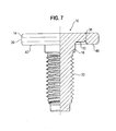
- the function element 10 is formed in Figs. 1A - 1C as a nut element, it could however equally be formed as a bolt element as is shown in Fig. 7 .
- the functional element could be formed as a hollow element or as an element with a cylindrical projection for receiving a shaft or a clip or a bearing sleeve (not shown).
- Adhesive bands are known which consists of carrier materials, for example plastic films or plastic foams, paper, metal foils or textile fabrics and which are coated on one side or on both sides with pressure sensitive adhesive. They are frequently also referred to as a double-sided adhesive tape.
- transfer adhesive bands are also used: these are carrier-free thin pressure sensitive adhesive films which can be covered prior to processing on both sides with waxed or siliconized protective paper.
- transfer adhesive bands or adhesives bands can for example be obtained from the company 3M. In the following transfer adhesive bands and double-sided adhesive bands will be collectively refererd to as "adhesive bands”.
- Such adhesive bands are frequently delivered by a supplier in the form of a coil of the actual adhesive in strip shape or label shape and is or are arranged on a strip of a protected film.
- the protective film comes into contact with both sides of an adhesive or of the labels so that two protective films are not required.
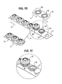
- adhesive rings 30 are used which are punched out appropriately for the shape of the fastener elements that are used, for example in the form of rings, such as an adhesive ring 30 of Figs. 1A to 1C .
- the so punched out adhesive band pieces can be subsequently separated from the protective film 29 of Fig. 1D by a suitable transfer device which is symbolized by the arrows P.
- the strip 29 is moved in the direction of the arrow R away from the coil (not shown), so that the transfer device can pick up or engage the individual rings 30. They are then placed one after the other by the transfer device P ontof a pre-pierced carrier band 31, which in this embodiment is moved in the direction of the arrow S.
- the carrier band 31 consists of a durable material such as for example a strip of plastic or a fabric strip which can also serve as a protective film or be covered by the protective film.
- the transfer takes place in this example in such a way that a first (lower) side 33 of the adhesive band ring 30 is connected to the carrier band 31 and a second (upper) free side 35 of the adhesive band ring 30 is freely accessible from above.
- a functional element 10 is then firmly connected to the free side 35 of the adhesive band ring 30. This can take place through a further transfer device which place the functional element 10 one after the other onto the respective adhesive tape rings 30 as is for example schematically shown by the arrow T.
- the functional element 10 can be guided in an ordered manner in the arrow direction U along a suitable guide 37 to the corresponding transfer device (T).
- the upper side 35 of the adhesive ring 30 then sticks to the attachment surface 12 of the respective functional element 10.
- the carrier band 31 is guided at a selected point in time, at which the functional element 10 are to be connected with components, into a processing machine in which the functional elements 10 and corresponding plastic parts are processed into a component assembly which will be later described in more detail in connection with Fig. 5 .
- the Fig. 2A now shows the functional element 10 of Figs. 1A to 1C in accordance with the invention arranged within a holder 50 which can for example be formed as a setting head.
- a setting head is extremely well known in the field of fastener elements for use with the sheet metal parts and do not need to be explained further here.
- the holder 50 of the setting head has a lower end face 52 and also a cutout 54 corresponding to the external shape of the functional element 10, with the cutout being so dimensioned that the contact surface 40 of the functional element 10 lies in a plane with the lower side 52 of the holder 50.
- Beneath the functional element 10 is located a plastic component which is supported on a die button 60.
- a hole 58 is present in the plastic component 56 with the margin of the hole defining an internal diameter which corresponds to the external diameter of a central projection 62 of the die button 60. This diameter likewise corresponds to the outer diameter D2 of the centering section 16 of the functional element 10.
- the central projection 62 of the die button, the hole in the plastic component 56 and also the centering section 16 of the functional element 10 have a common central longitudinal axis 64.
- the plastic component 56 also lies in this stadium concentric to the centering section 16 of the functional element.
- the central projection 62 of the die button in a lower region 66 of the central projection 62 serves for the centering of the plastic component 56 and only in an upper region for the centering of the functional element 10.
- a ring-like cutout 68 of the central post 62 which has a form which deviates slightly from the shape of the lower region 70 of the centering section 16 so that this region of the centering section 16 is slightly compressed, slightly reshaped and fractionally dilated when the holder or the setting head 50 is pressed against the ring-like driven surface 20 of the functional element 10 in the direction of the arrow F.
- the die button 60 is centered in the lower tool of a press while the holder 50 or the setting head is arranged either in the intermediate plate of the press (if present) or in an upper tool of the press.
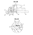
- the holder 50 On closing of the press, the holder 50 is thus moved towards the plastic component 56 and the die button 60, with the upper side 72 of the plastic component in the region around the hole 58 being pressed against the adhesive ring and also with the internal margin of the hole 58 scraping adhesive from the centering section 16 and hereby subjecting the adhesive ring 30 to pressure so that the components of the adhesive react together and are set under pressure and the adhesive cures.
- the capsules burst under the applied pressure and allow the corresponding components to enter into an intimate mixture with one another whereby the chemical curing reaction is triggered.
- the accurate fitted shape of the outer surface of the centering section 16 and the margin of the hole of the opening or the aperture 58 of the plastic component ensure that no adhesive or only a very small quantity of adhesive runs past the centering section 16 i.e. this region is well sealed so that the adhesive is set under pressure in the now rectangular space 74 between the upper side of the plastic component and the attachment surface 38 of the functional element 10 and cures there, as is shown in Figs. 2B and 2C .
- excess adhesive enters into the ring recess 38 around the attachment surface 38.
- the contact surface 40 of the functional element 10 likewise sealingly lies against the surface 70 of the plastic component 56 but does not however press into this or only to a small degree.
- the axial height h in accordance with Fig. 1B also determines the axial thickness of the hardened or cured quantity of adhesive 76 which fills the rectangular space (in cross-section) 74.
- the contact surface 40 of the functional element is pressed against the upper side 72 of the plastic component, so that a high quality attachment situation is achieved with the desired direct clamping. Since the adhesive is cured in the adhesive joint 74 a part of the axial loading of the screw connection is transferred via the adhesive in the adhesive joint 74 to the attachment surface 12.
- Figs. 3A and 3B show an alternative embodiment of the functional element 10.
- the same reference numerals are used as in the embodiment of figs, 1A to 1C and 2A to 2C and it will be understood that the corresponding description also applies to the features which are designated with the same reference numerals.
- the embodiment of Figs, 3Aand 3B has the difference that the attachment surface 12 extends over the full lower side of the flange 14 radially outside the centering section 16.
- the adhesive ring 30 also has a corresponding extent. In this way the two sided adhesive connection with a corresponding adhesive strength and a relatively simple form of the functional element 110 is achieved.
- a bolt element corresponding to Fig. 7 can be realised with a correspondingly extended attachment surface 12, i.e. also withouta curved contact surface 40.
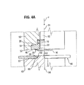
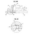
- FIGS. 4A to 4C show an embodiment which is very similar to the embodiment of Figs. 2A - 2C , which is why the same reference numerals are used in the corresponding drawings. It will be understood that the previous description also applies for components with the same reference numerals in Figs. 4A - 4C . This convention is also used in conjunction with the further Figures. The important differences between the embodiment in accordance with Figs. 4A - 4C in comparison to the Figs. 2A - 2C will now be described.
- the raised portion 80 of ring shape of the die button forms a ring recess 84 in the lower side 78 of the plastic component and at the same time, as can be best seen from Fig. 4C , a corresponding raised portion 86 on the surface of the plastic component, whereby the axial height of the adhesive with the adhesive joint 74 is reduced relative to the embodiment of Figs. 2B and 2C .
- This can be of advantage, since frequently, the adhesive force of adhesives increases with the reducing thickness of the adhesive layer providing this layer still has an appropriate thickness.
- the axial height of the raised portion 80 relative to the surface 82 can with advantage be selected in the range between 0.2 and 0.5 mm.
- the difference between the axial height of the contact surface 40 and the attachment surface 12 is then so selected that the axial height of the adhesive layer in the region 74 amounts to approximately 0.1 mm if one takes account of the axial height of the raised portion 86 which approximately amounts to the axial height of the recess 84 or of the ring surface 80 relative to the surface 82.
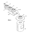
- Fig. 6 now shows how individual functional elements 10 can be inserted into corresponding openings 100 of a carrier band 102 so that the functional elements are arranged one after the other in a row.
- the carrier band 102 can be the carrier band 31 in accordance with Figs. 1D and 1E , which is not however necessarily the case. If necessary, a plurality of rows of openings 100 can be provided in the carrier band so that plural rows of functional elements are also possible.
- the functional elements 10 are buttoned out of the carrier band one after the other on movement of the carrier band 102 in the arrow direction B and they can then be moved into a feed passage of a setting head or to a position above a die button 60 by means of a movable finger or of a holder (both not shown) which directly receives the functional element, as schematically shown in Fig. 6.
- Fig. 6 shows however the situation after the attachment of the plastic component 56.
- a large number of different types of adhesives is known for the connection of various components.
- the different types of adhesive can be classified on the one hand by their chemical bases and on the other hand by their solidification mechanism.
- reaction adhesives often also termed reaction adhesives, the individual chemical components for the adhesive are introduced in the correct ratio into the adhesive joint.
- the solidification is achieved by chemical reaction of the components with one another. Basically, one distinguishes for reaction adhesives between two (or multi) component systems and single-component systems. In the present application, any kind of reaction adhesives can be used and for the sake of simplicity will be termed in the following as adhesives.
- Two often spatially separated preparations are used. Monomers, the basic building stones of the polymer arising during the reaction, are present in these preparations.
- One of the two preparations contains resin monomers (binder) whereas the other contains hardener.
- Further content materials can also be present in the preparations, such as for example stabilizers, thixotropic agents, accelerators, further additives, dyes or fillers.
- the two components must typically be mixed in the correct ratio with one another prior to the application. On contact of the binder and the hardener, the chemical reaction to form the adhesive polymer starts. This signifies that two component adhesives can only be processed within a certain processing time.
- the viscosity of the mixture continuously increases and can finally no longer join the two surfaces to be joined to one another after exceeding the processing time if these surfaces have not yet been brought together.
- the curing time follows in which the end strength of the adhesive bond builds up. This curing time is affected greatly by external influences, in particular by the temperature. A temperature increase leads to an accelerated curing and often also to higher strength. In contrast to this, lower temperatures prolong the curing time.
- Three or multi-component adhesives are also manufactured which can be used as required.
- Typical types of two (or multi) components and single-component systems are cyanacrylate adhesives, methylmethacrylat adhesives, anaerobically curing adhesives, radiation curing adhesives, phenol formaldehyde resin adhesives, epoxy resin adhesives and polyurethane adhesives.
- An example for a three component adhesive would be an epoxy resin as a first component, an epoxy resin polymeric compound as the second component and a hardener, for example in the form of a peroxide as the third component.
Landscapes
- Engineering & Computer Science (AREA)
- Mechanical Engineering (AREA)
- General Engineering & Computer Science (AREA)
- Chemical & Material Sciences (AREA)
- Chemical Kinetics & Catalysis (AREA)
- General Chemical & Material Sciences (AREA)
- Standing Axle, Rod, Or Tube Structures Coupled By Welding, Adhesion, Or Deposition (AREA)
- Lining Or Joining Of Plastics Or The Like (AREA)
- Insulators (AREA)
- Connection Of Plates (AREA)
- Adhesives Or Adhesive Processes (AREA)
Applications Claiming Priority (1)
| Application Number | Priority Date | Filing Date | Title |
|---|---|---|---|
| DE102010047637A DE102010047637A1 (de) | 2010-10-06 | 2010-10-06 | Funktionselement |
Publications (3)
| Publication Number | Publication Date |
|---|---|
| EP2439055A2 true EP2439055A2 (de) | 2012-04-11 |
| EP2439055A3 EP2439055A3 (de) | 2016-08-31 |
| EP2439055B1 EP2439055B1 (de) | 2020-08-05 |
Family
ID=44862279
Family Applications (1)
| Application Number | Title | Priority Date | Filing Date |
|---|---|---|---|
| EP11008061.1A Active EP2439055B1 (de) | 2010-10-06 | 2011-10-05 | Funktionales Element zur Befestigung an einer Kunststoffkomponente und Komponentenanordnung |
Country Status (5)
| Country | Link |
|---|---|
| US (2) | US8888426B2 (de) |
| EP (1) | EP2439055B1 (de) |
| CN (1) | CN102537001B (de) |
| DE (1) | DE102010047637A1 (de) |
| ES (1) | ES2824844T3 (de) |
Cited By (4)
| Publication number | Priority date | Publication date | Assignee | Title |
|---|---|---|---|---|
| EP3217024A1 (de) | 2016-03-08 | 2017-09-13 | Profil Verbindungstechnik GmbH & Co. KG | Funktionselement |
| DE102016114476A1 (de) | 2016-08-04 | 2018-02-08 | Profil Verbindungstechnik Gmbh & Co. Kg | Vorrichtung und Verfahren zur Anbringung von Funktionselementen auf einem Bauteil |
| DE102016117418A1 (de) | 2016-09-15 | 2018-03-15 | Profil Verbindungstechnik Gmbh & Co. Kg | Funktionselement |
| WO2018209141A1 (en) * | 2017-05-10 | 2018-11-15 | Vinyl Technology, Inc. | Method of bonding a metal fitting to a polyurethane structure |
Families Citing this family (12)
| Publication number | Priority date | Publication date | Assignee | Title |
|---|---|---|---|---|
| DE102010047636A1 (de) * | 2010-10-06 | 2012-04-12 | Profil Verbindungstechnik Gmbh & Co. Kg | Funktionselement zur Anbringung an einem Kunststoffbauteil, ein Zusammenbauteil, eine Matrize und Verfahren |
| US11098748B2 (en) | 2013-03-24 | 2021-08-24 | Crushlock, Inc. | One-piece self-locking nut |
| US20180172045A1 (en) * | 2016-12-17 | 2018-06-21 | Ford Global Technologies, Llc | Friction Element Weld Element Modification To Increase Corrosion Resistance of Thermal Mechanical Joint |
| DE102017200575B4 (de) * | 2017-01-16 | 2025-10-30 | Bayerische Motoren Werke Aktiengesellschaft | Verfahren zum Herstellen eines Bauteils |
| US10309439B2 (en) * | 2017-01-26 | 2019-06-04 | Crushlock, Inc. | High torque bolt |
| DE102017008313A1 (de) * | 2017-09-05 | 2019-03-07 | Diehl Aviation Laupheim Gmbh | Klebefuß, Klebeanordnung und Klebeverfahren |
| AU2018353120B2 (en) * | 2017-10-19 | 2024-11-21 | Security Locknut, LLC | Fastener systems and methods |
| US11111945B2 (en) | 2018-04-05 | 2021-09-07 | Crushlock, Inc. | Multi-piece bolts and methods of making the same |
| DE102018212212B4 (de) * | 2018-07-23 | 2025-07-10 | SEKO Consulting GmbH | Befestigungshülsenanordnung mit formschlüssiger Verbindung |
| US20210317862A1 (en) * | 2018-08-22 | 2021-10-14 | Omg, Inc. | Self-Sealing Fastener and Collated Strips Thereof for Integrated Sheathing |
| DE102020111696A1 (de) * | 2020-04-29 | 2021-11-04 | Profil Verbindungstechnik Gmbh & Co. Kg | Funktionselement |
| CN114233732B (zh) * | 2021-12-15 | 2024-02-27 | 北京机科国创轻量化科学研究院有限公司 | 一种胶粘式复合材料连接件及利用其连接复合板材的方法 |
Citations (2)
| Publication number | Priority date | Publication date | Assignee | Title |
|---|---|---|---|---|
| EP1116891A1 (de) | 1994-11-22 | 2001-07-18 | Profil Verbindungstechnik GmbH & Co. KG | Einpressmutter |
| DE102004062391A1 (de) | 2004-12-23 | 2006-07-13 | Profil-Verbindungstechnik Gmbh & Co. Kg | Ein durch Nieten an ein Blechteil anbringbares Element sowie Zusammenbauteil und Verfahren zur Erzeugung des Zusammenbauteils |
Family Cites Families (38)
| Publication number | Priority date | Publication date | Assignee | Title |
|---|---|---|---|---|
| US2775917A (en) * | 1951-07-31 | 1957-01-01 | American Marietta Co | Sheet metal nut with sealing means |
| US2927495A (en) * | 1957-02-20 | 1960-03-08 | Victor H Barwood | Composite self-sealing washer |
| US3399589A (en) * | 1965-12-29 | 1968-09-03 | Lamson & Sessions Co | Sealing fastener |
| BE792010Q (fr) * | 1966-03-11 | 1973-03-16 | Hoff Stevens | Construction de joint |
| US3747657A (en) * | 1971-04-23 | 1973-07-24 | Value Eng Co Inc | Nut type fastener |
| DE2536319C3 (de) | 1975-08-14 | 1981-11-19 | Rudolf 8019 Moosach Hinterwaldner | Härtbare Masse und Verfahren zu deren Härtung |
| GB2013300B (en) * | 1978-01-25 | 1982-06-30 | Messerschmitt Boelkow Blohm | Nut and flange assemblies |
| US4250596A (en) * | 1979-11-19 | 1981-02-17 | Nifco, Inc. | Fastening system for securing a trim-fixing device to a substrate |
| GB2067253A (en) * | 1980-01-11 | 1981-07-22 | United Carr Ltd | Aperture plug |
| US4536524A (en) | 1981-04-21 | 1985-08-20 | Capsulated Systems, Inc. | Microencapsulated epoxy adhesive system |
| US4448565A (en) * | 1982-03-17 | 1984-05-15 | Illinois Tool Works Inc. | Stress relieving nut member |
| US4523883A (en) * | 1982-10-18 | 1985-06-18 | Illinois Tool Works Inc. | Printed circuit board fastener |
| US4657460A (en) * | 1986-03-17 | 1987-04-14 | Chrysler Motors Corporation | Self-bonding threaded fasteners and method of curing same |
| DE3831308C1 (de) * | 1988-09-15 | 1990-01-18 | Dr.Ing.H.C. F. Porsche Ag, 7000 Stuttgart, De | |
| US5051049A (en) * | 1990-10-29 | 1991-09-24 | Wills Kevin P | Sticky nut fastener |
| US5304023A (en) * | 1992-10-23 | 1994-04-19 | Metaltite Corporation | Metal panel fastener |
| US6375872B1 (en) | 1992-11-17 | 2002-04-23 | Moore Business Forms | Microencapsulated adhesive |
| US5827924A (en) | 1993-06-16 | 1998-10-27 | Korea Research Institute Of Chemical Technology | Polymer sealant microencapsulated by polyurethane reaction and its binder solution |
| DE4402550A1 (de) | 1994-01-28 | 1995-08-03 | Raymond A Gmbh & Co Kg | Verklebbares Befestigungselement zum Halten von Bau- oder Funktionsteilen auf Trägerteilen |
| US5725345A (en) * | 1994-09-26 | 1998-03-10 | Zhov; Peng | Tire repair screw with sealing material |
| FR2731984B1 (fr) * | 1995-03-21 | 1997-04-30 | Rapid Sa | Bouchon d'obturation d'une ouverture quelconque et procede de fabrication de ce bouchon |
| US5636953A (en) * | 1996-06-11 | 1997-06-10 | Trw Inc. | Roof rail attachment assembly |
| DE19645886C2 (de) * | 1996-11-07 | 1998-10-08 | Bosch Gmbh Robert | Schraubverbindung mit Befestigungsschraube |
| GB9816472D0 (en) * | 1998-07-30 | 1998-09-23 | Ariel Ind Plc | Multiple fastener application system |
| US6669428B2 (en) * | 2000-11-01 | 2003-12-30 | Argent International, Inc. | Locating door hinge washer device for hinge assembly |
| US6736406B1 (en) * | 2001-05-04 | 2004-05-18 | Brian G. Provencher | Self-adhesive gasket |
| US6773780B2 (en) * | 2001-08-14 | 2004-08-10 | Physical Systems, Inc. | Self fixturing adhesive attachment |
| US7048486B2 (en) * | 2002-07-10 | 2006-05-23 | Newfrey Llc | Insert part for a wall opening, in particular on a vehicle body |
| ITMO20040242A1 (it) * | 2004-09-21 | 2004-12-21 | Syfal Spa | Metodo e mezzi per fissare stabilmete organi di aggancio a superfici. |
| DE102005041350A1 (de) * | 2005-08-31 | 2007-03-01 | Ejot Gmbh & Co. Kg | Mit einem Loch einer Platte fluchtendes Mutterteil für ein Befestigungsmittel |
| DE102005044462A1 (de) | 2005-09-16 | 2007-03-22 | Fritz Egger Gmbh & Co. | Verbindung zwischen Fügeflächen von zwei Bauteilen |
| US7527463B2 (en) * | 2006-03-10 | 2009-05-05 | Gm Global Technology Operations, Inc. | Nut and method for adhesive nut attachment |
| US7878744B2 (en) * | 2006-06-06 | 2011-02-01 | Nd Industries, Inc. | Fibrous microencapsulated washer for fasteners |
| US7645105B2 (en) * | 2006-06-27 | 2010-01-12 | Gm Global Technology Operations, Inc. | Projection welded fastener with integral sealer |
| DE102007019253C5 (de) | 2007-04-24 | 2013-07-04 | Gesipa Blindniettechnik Gmbh | Blindnietmutter |
| DE102008058390A1 (de) * | 2008-11-21 | 2010-06-02 | Sfs Intec Holding Ag | Punktbefestiger, Klebeverbindung und Verfahren zum Herstellen einer Klebeverbindung |
| DE102009042336A1 (de) | 2009-09-21 | 2011-03-24 | Profil Verbindungstechnik Gmbh & Co. Kg | Selbststanzendes hohles Einpresselement, Zusammenbauteil bestehend aus einem Einpresselement und einem Blechteil sowie ein Verfahren zur Herstellung einer selbststanzenden Einpressmutter sowie zur Anbringung einer selbststanzenden Einpressmutter |
| DE102010047636A1 (de) * | 2010-10-06 | 2012-04-12 | Profil Verbindungstechnik Gmbh & Co. Kg | Funktionselement zur Anbringung an einem Kunststoffbauteil, ein Zusammenbauteil, eine Matrize und Verfahren |
-
2010
- 2010-10-06 DE DE102010047637A patent/DE102010047637A1/de not_active Ceased
-
2011
- 2011-10-05 ES ES11008061T patent/ES2824844T3/es active Active
- 2011-10-05 EP EP11008061.1A patent/EP2439055B1/de active Active
- 2011-10-06 US US13/267,001 patent/US8888426B2/en active Active
- 2011-10-08 CN CN201110301499.6A patent/CN102537001B/zh not_active Expired - Fee Related
-
2014
- 2014-10-20 US US14/518,985 patent/US9651081B2/en active Active
Patent Citations (2)
| Publication number | Priority date | Publication date | Assignee | Title |
|---|---|---|---|---|
| EP1116891A1 (de) | 1994-11-22 | 2001-07-18 | Profil Verbindungstechnik GmbH & Co. KG | Einpressmutter |
| DE102004062391A1 (de) | 2004-12-23 | 2006-07-13 | Profil-Verbindungstechnik Gmbh & Co. Kg | Ein durch Nieten an ein Blechteil anbringbares Element sowie Zusammenbauteil und Verfahren zur Erzeugung des Zusammenbauteils |
Cited By (14)
| Publication number | Priority date | Publication date | Assignee | Title |
|---|---|---|---|---|
| US10315363B2 (en) | 2016-03-08 | 2019-06-11 | Profil Verbindungstechnik Gmbh & Co. Kg | Functional element |
| DE102016104187A1 (de) | 2016-03-08 | 2017-09-14 | Profil Verbindungstechnik Gmbh & Co. Kg | Funktionselement |
| EP3217024A1 (de) | 2016-03-08 | 2017-09-13 | Profil Verbindungstechnik GmbH & Co. KG | Funktionselement |
| DE102016114476A1 (de) | 2016-08-04 | 2018-02-08 | Profil Verbindungstechnik Gmbh & Co. Kg | Vorrichtung und Verfahren zur Anbringung von Funktionselementen auf einem Bauteil |
| US20200189206A1 (en) * | 2016-09-15 | 2020-06-18 | Profil Verbindungstechnik Gmbh & Co. Kg | Functional element |
| EP3296577A1 (de) * | 2016-09-15 | 2018-03-21 | Profil Verbindungstechnik GmbH & Co. KG | Funktionselement |
| US20180071992A1 (en) * | 2016-09-15 | 2018-03-15 | Profil Verbindungstechnik Gmbh & Co. Kg | Functional element |
| DE102016117418A1 (de) | 2016-09-15 | 2018-03-15 | Profil Verbindungstechnik Gmbh & Co. Kg | Funktionselement |
| US11511495B2 (en) * | 2016-09-15 | 2022-11-29 | Profil Verbindungstechnik Gmbh & Co. Kg | Functional element |
| WO2018209141A1 (en) * | 2017-05-10 | 2018-11-15 | Vinyl Technology, Inc. | Method of bonding a metal fitting to a polyurethane structure |
| CN110891771A (zh) * | 2017-05-10 | 2020-03-17 | 乙烯技术公司 | 将金属配件结合聚氨酯结构的方法 |
| JP2020519510A (ja) * | 2017-05-10 | 2020-07-02 | ビニル テクノロジー インコーポレイテッドVinyl Technology,Inc. | ポリウレタン構造に金具を接着する方法 |
| US10723083B2 (en) | 2017-05-10 | 2020-07-28 | Vinyl Technology, Inc. | Polyurethane bonding process for fuel bladders |
| CN110891771B (zh) * | 2017-05-10 | 2022-04-15 | 乙烯技术公司 | 将金属配件结合聚氨酯结构的方法 |
Also Published As
| Publication number | Publication date |
|---|---|
| ES2824844T3 (es) | 2021-05-13 |
| US20150037114A1 (en) | 2015-02-05 |
| EP2439055B1 (de) | 2020-08-05 |
| EP2439055A3 (de) | 2016-08-31 |
| US8888426B2 (en) | 2014-11-18 |
| DE102010047637A1 (de) | 2012-04-12 |
| US9651081B2 (en) | 2017-05-16 |
| CN102537001B (zh) | 2016-01-20 |
| CN102537001A (zh) | 2012-07-04 |
| US20120087764A1 (en) | 2012-04-12 |
Similar Documents
| Publication | Publication Date | Title |
|---|---|---|
| US9651081B2 (en) | Functional element for attachment to a plastic component and a component assembly | |
| US9188148B2 (en) | Functional element for attachment to a plastic component, a component assembly, a die button and method | |
| US20180313391A1 (en) | Functional element for attachment to a plastic component and a component assembly | |
| US8465241B2 (en) | Composite fasteners containing multiple reinforcing fiber types | |
| US9937693B2 (en) | Adhesive bolt and attachment method | |
| US5667868A (en) | Outer door panel and method for molding and attaching same | |
| US7131807B1 (en) | Functional element, method for fixing it in a sheet metal part, assembling element and swaging assembly | |
| US20150219140A1 (en) | Method for manufacturing an assembly unit and fastening unit for carrying out the method | |
| US10315363B2 (en) | Functional element | |
| US7182561B2 (en) | Blind rivet with steal | |
| US8161616B2 (en) | Method of manufacture for a plastic-capped panel fastener | |
| EP2802785B1 (de) | Verfahren zum verkleben eines befestigungselementes an einem trägerbauteil eines kraftfahrzeugs | |
| US11511495B2 (en) | Functional element | |
| DE202015105594U1 (de) | System für die Montage von Fahrzeugbauteilen mit verstärktem formbaren Niet | |
| US10239285B2 (en) | Spinning joining of similar and dissimilar materials | |
| US20230286222A1 (en) | Method for joining a fastener to a workpiece | |
| US20210354354A1 (en) | Connecting element, component of a composite material and method for producing a component from a composite material | |
| US5473806A (en) | Method for preventing cold welding especially of blind rivets | |
| CN119802065A (zh) | 与紫外光敏感粘合剂一起使用的紧固件 |
Legal Events
| Date | Code | Title | Description |
|---|---|---|---|
| AK | Designated contracting states |
Kind code of ref document: A2 Designated state(s): AL AT BE BG CH CY CZ DE DK EE ES FI FR GB GR HR HU IE IS IT LI LT LU LV MC MK MT NL NO PL PT RO RS SE SI SK SM TR |
|
| AX | Request for extension of the european patent |
Extension state: BA ME |
|
| PUAI | Public reference made under article 153(3) epc to a published international application that has entered the european phase |
Free format text: ORIGINAL CODE: 0009012 |
|
| PUAL | Search report despatched |
Free format text: ORIGINAL CODE: 0009013 |
|
| AK | Designated contracting states |
Kind code of ref document: A3 Designated state(s): AL AT BE BG CH CY CZ DE DK EE ES FI FR GB GR HR HU IE IS IT LI LT LU LV MC MK MT NL NO PL PT RO RS SE SI SK SM TR |
|
| AX | Request for extension of the european patent |
Extension state: BA ME |
|
| RIC1 | Information provided on ipc code assigned before grant |
Ipc: F16B 37/06 20060101ALI20160722BHEP Ipc: F16B 27/00 20060101ALI20160722BHEP Ipc: B29C 65/48 20060101AFI20160722BHEP Ipc: F16B 11/00 20060101ALI20160722BHEP |
|
| 17P | Request for examination filed |
Effective date: 20161006 |
|
| RBV | Designated contracting states (corrected) |
Designated state(s): AL AT BE BG CH CY CZ DE DK EE ES FI FR GB GR HR HU IE IS IT LI LT LU LV MC MK MT NL NO PL PT RO RS SE SI SK SM TR |
|
| STAA | Information on the status of an ep patent application or granted ep patent |
Free format text: STATUS: EXAMINATION IS IN PROGRESS |
|
| 17Q | First examination report despatched |
Effective date: 20170705 |
|
| GRAP | Despatch of communication of intention to grant a patent |
Free format text: ORIGINAL CODE: EPIDOSNIGR1 |
|
| STAA | Information on the status of an ep patent application or granted ep patent |
Free format text: STATUS: GRANT OF PATENT IS INTENDED |
|
| INTG | Intention to grant announced |
Effective date: 20200306 |
|
| GRAS | Grant fee paid |
Free format text: ORIGINAL CODE: EPIDOSNIGR3 |
|
| GRAA | (expected) grant |
Free format text: ORIGINAL CODE: 0009210 |
|
| STAA | Information on the status of an ep patent application or granted ep patent |
Free format text: STATUS: THE PATENT HAS BEEN GRANTED |
|
| AK | Designated contracting states |
Kind code of ref document: B1 Designated state(s): AL AT BE BG CH CY CZ DE DK EE ES FI FR GB GR HR HU IE IS IT LI LT LU LV MC MK MT NL NO PL PT RO RS SE SI SK SM TR |
|
| REG | Reference to a national code |
Ref country code: GB Ref legal event code: FG4D |
|
| REG | Reference to a national code |
Ref country code: CH Ref legal event code: EP |
|
| REG | Reference to a national code |
Ref country code: AT Ref legal event code: REF Ref document number: 1298120 Country of ref document: AT Kind code of ref document: T Effective date: 20200815 |
|
| REG | Reference to a national code |
Ref country code: DE Ref legal event code: R096 Ref document number: 602011068044 Country of ref document: DE |
|
| REG | Reference to a national code |
Ref country code: IE Ref legal event code: FG4D |
|
| REG | Reference to a national code |
Ref country code: LT Ref legal event code: MG4D |
|
| REG | Reference to a national code |
Ref country code: NL Ref legal event code: MP Effective date: 20200805 |
|
| REG | Reference to a national code |
Ref country code: AT Ref legal event code: MK05 Ref document number: 1298120 Country of ref document: AT Kind code of ref document: T Effective date: 20200805 |
|
| PG25 | Lapsed in a contracting state [announced via postgrant information from national office to epo] |
Ref country code: BG Free format text: LAPSE BECAUSE OF FAILURE TO SUBMIT A TRANSLATION OF THE DESCRIPTION OR TO PAY THE FEE WITHIN THE PRESCRIBED TIME-LIMIT Effective date: 20201105 Ref country code: AT Free format text: LAPSE BECAUSE OF FAILURE TO SUBMIT A TRANSLATION OF THE DESCRIPTION OR TO PAY THE FEE WITHIN THE PRESCRIBED TIME-LIMIT Effective date: 20200805 Ref country code: GR Free format text: LAPSE BECAUSE OF FAILURE TO SUBMIT A TRANSLATION OF THE DESCRIPTION OR TO PAY THE FEE WITHIN THE PRESCRIBED TIME-LIMIT Effective date: 20201106 Ref country code: NO Free format text: LAPSE BECAUSE OF FAILURE TO SUBMIT A TRANSLATION OF THE DESCRIPTION OR TO PAY THE FEE WITHIN THE PRESCRIBED TIME-LIMIT Effective date: 20201105 Ref country code: LT Free format text: LAPSE BECAUSE OF FAILURE TO SUBMIT A TRANSLATION OF THE DESCRIPTION OR TO PAY THE FEE WITHIN THE PRESCRIBED TIME-LIMIT Effective date: 20200805 Ref country code: FI Free format text: LAPSE BECAUSE OF FAILURE TO SUBMIT A TRANSLATION OF THE DESCRIPTION OR TO PAY THE FEE WITHIN THE PRESCRIBED TIME-LIMIT Effective date: 20200805 Ref country code: SE Free format text: LAPSE BECAUSE OF FAILURE TO SUBMIT A TRANSLATION OF THE DESCRIPTION OR TO PAY THE FEE WITHIN THE PRESCRIBED TIME-LIMIT Effective date: 20200805 Ref country code: HR Free format text: LAPSE BECAUSE OF FAILURE TO SUBMIT A TRANSLATION OF THE DESCRIPTION OR TO PAY THE FEE WITHIN THE PRESCRIBED TIME-LIMIT Effective date: 20200805 Ref country code: PT Free format text: LAPSE BECAUSE OF FAILURE TO SUBMIT A TRANSLATION OF THE DESCRIPTION OR TO PAY THE FEE WITHIN THE PRESCRIBED TIME-LIMIT Effective date: 20201207 |
|
| PG25 | Lapsed in a contracting state [announced via postgrant information from national office to epo] |
Ref country code: LV Free format text: LAPSE BECAUSE OF FAILURE TO SUBMIT A TRANSLATION OF THE DESCRIPTION OR TO PAY THE FEE WITHIN THE PRESCRIBED TIME-LIMIT Effective date: 20200805 Ref country code: RS Free format text: LAPSE BECAUSE OF FAILURE TO SUBMIT A TRANSLATION OF THE DESCRIPTION OR TO PAY THE FEE WITHIN THE PRESCRIBED TIME-LIMIT Effective date: 20200805 Ref country code: PL Free format text: LAPSE BECAUSE OF FAILURE TO SUBMIT A TRANSLATION OF THE DESCRIPTION OR TO PAY THE FEE WITHIN THE PRESCRIBED TIME-LIMIT Effective date: 20200805 Ref country code: NL Free format text: LAPSE BECAUSE OF FAILURE TO SUBMIT A TRANSLATION OF THE DESCRIPTION OR TO PAY THE FEE WITHIN THE PRESCRIBED TIME-LIMIT Effective date: 20200805 Ref country code: IS Free format text: LAPSE BECAUSE OF FAILURE TO SUBMIT A TRANSLATION OF THE DESCRIPTION OR TO PAY THE FEE WITHIN THE PRESCRIBED TIME-LIMIT Effective date: 20201205 |
|
| PG25 | Lapsed in a contracting state [announced via postgrant information from national office to epo] |
Ref country code: CZ Free format text: LAPSE BECAUSE OF FAILURE TO SUBMIT A TRANSLATION OF THE DESCRIPTION OR TO PAY THE FEE WITHIN THE PRESCRIBED TIME-LIMIT Effective date: 20200805 Ref country code: EE Free format text: LAPSE BECAUSE OF FAILURE TO SUBMIT A TRANSLATION OF THE DESCRIPTION OR TO PAY THE FEE WITHIN THE PRESCRIBED TIME-LIMIT Effective date: 20200805 Ref country code: DK Free format text: LAPSE BECAUSE OF FAILURE TO SUBMIT A TRANSLATION OF THE DESCRIPTION OR TO PAY THE FEE WITHIN THE PRESCRIBED TIME-LIMIT Effective date: 20200805 Ref country code: RO Free format text: LAPSE BECAUSE OF FAILURE TO SUBMIT A TRANSLATION OF THE DESCRIPTION OR TO PAY THE FEE WITHIN THE PRESCRIBED TIME-LIMIT Effective date: 20200805 Ref country code: SM Free format text: LAPSE BECAUSE OF FAILURE TO SUBMIT A TRANSLATION OF THE DESCRIPTION OR TO PAY THE FEE WITHIN THE PRESCRIBED TIME-LIMIT Effective date: 20200805 |
|
| REG | Reference to a national code |
Ref country code: DE Ref legal event code: R097 Ref document number: 602011068044 Country of ref document: DE |
|
| REG | Reference to a national code |
Ref country code: ES Ref legal event code: FG2A Ref document number: 2824844 Country of ref document: ES Kind code of ref document: T3 Effective date: 20210513 |
|
| PG25 | Lapsed in a contracting state [announced via postgrant information from national office to epo] |
Ref country code: AL Free format text: LAPSE BECAUSE OF FAILURE TO SUBMIT A TRANSLATION OF THE DESCRIPTION OR TO PAY THE FEE WITHIN THE PRESCRIBED TIME-LIMIT Effective date: 20200805 |
|
| REG | Reference to a national code |
Ref country code: CH Ref legal event code: PL |
|
| PLBE | No opposition filed within time limit |
Free format text: ORIGINAL CODE: 0009261 |
|
| STAA | Information on the status of an ep patent application or granted ep patent |
Free format text: STATUS: NO OPPOSITION FILED WITHIN TIME LIMIT |
|
| PG25 | Lapsed in a contracting state [announced via postgrant information from national office to epo] |
Ref country code: MC Free format text: LAPSE BECAUSE OF FAILURE TO SUBMIT A TRANSLATION OF THE DESCRIPTION OR TO PAY THE FEE WITHIN THE PRESCRIBED TIME-LIMIT Effective date: 20200805 Ref country code: LU Free format text: LAPSE BECAUSE OF NON-PAYMENT OF DUE FEES Effective date: 20201005 Ref country code: SK Free format text: LAPSE BECAUSE OF FAILURE TO SUBMIT A TRANSLATION OF THE DESCRIPTION OR TO PAY THE FEE WITHIN THE PRESCRIBED TIME-LIMIT Effective date: 20200805 |
|
| 26N | No opposition filed |
Effective date: 20210507 |
|
| REG | Reference to a national code |
Ref country code: BE Ref legal event code: MM Effective date: 20201031 |
|
| PG25 | Lapsed in a contracting state [announced via postgrant information from national office to epo] |
Ref country code: CH Free format text: LAPSE BECAUSE OF NON-PAYMENT OF DUE FEES Effective date: 20201031 Ref country code: BE Free format text: LAPSE BECAUSE OF NON-PAYMENT OF DUE FEES Effective date: 20201031 Ref country code: SI Free format text: LAPSE BECAUSE OF FAILURE TO SUBMIT A TRANSLATION OF THE DESCRIPTION OR TO PAY THE FEE WITHIN THE PRESCRIBED TIME-LIMIT Effective date: 20200805 Ref country code: LI Free format text: LAPSE BECAUSE OF NON-PAYMENT OF DUE FEES Effective date: 20201031 |
|
| PG25 | Lapsed in a contracting state [announced via postgrant information from national office to epo] |
Ref country code: IE Free format text: LAPSE BECAUSE OF NON-PAYMENT OF DUE FEES Effective date: 20201005 |
|
| PG25 | Lapsed in a contracting state [announced via postgrant information from national office to epo] |
Ref country code: MT Free format text: LAPSE BECAUSE OF FAILURE TO SUBMIT A TRANSLATION OF THE DESCRIPTION OR TO PAY THE FEE WITHIN THE PRESCRIBED TIME-LIMIT Effective date: 20200805 Ref country code: CY Free format text: LAPSE BECAUSE OF FAILURE TO SUBMIT A TRANSLATION OF THE DESCRIPTION OR TO PAY THE FEE WITHIN THE PRESCRIBED TIME-LIMIT Effective date: 20200805 |
|
| PG25 | Lapsed in a contracting state [announced via postgrant information from national office to epo] |
Ref country code: MK Free format text: LAPSE BECAUSE OF FAILURE TO SUBMIT A TRANSLATION OF THE DESCRIPTION OR TO PAY THE FEE WITHIN THE PRESCRIBED TIME-LIMIT Effective date: 20200805 |
|
| PGFP | Annual fee paid to national office [announced via postgrant information from national office to epo] |
Ref country code: IT Payment date: 20250922 Year of fee payment: 15 |
|
| PGFP | Annual fee paid to national office [announced via postgrant information from national office to epo] |
Ref country code: GB Payment date: 20250821 Year of fee payment: 15 |
|
| PGFP | Annual fee paid to national office [announced via postgrant information from national office to epo] |
Ref country code: FR Payment date: 20250821 Year of fee payment: 15 |
|
| PGFP | Annual fee paid to national office [announced via postgrant information from national office to epo] |
Ref country code: DE Payment date: 20250819 Year of fee payment: 15 |
|
| PGFP | Annual fee paid to national office [announced via postgrant information from national office to epo] |
Ref country code: TR Payment date: 20251001 Year of fee payment: 15 |
|
| PGFP | Annual fee paid to national office [announced via postgrant information from national office to epo] |
Ref country code: ES Payment date: 20251106 Year of fee payment: 15 |