EP2439353A2 - Wärmeerfassungssystem - Google Patents
Wärmeerfassungssystem Download PDFInfo
- Publication number
- EP2439353A2 EP2439353A2 EP11184217A EP11184217A EP2439353A2 EP 2439353 A2 EP2439353 A2 EP 2439353A2 EP 11184217 A EP11184217 A EP 11184217A EP 11184217 A EP11184217 A EP 11184217A EP 2439353 A2 EP2439353 A2 EP 2439353A2
- Authority
- EP
- European Patent Office
- Prior art keywords
- heat
- panels
- building
- panel
- heat transfer
- Prior art date
- Legal status (The legal status is an assumption and is not a legal conclusion. Google has not performed a legal analysis and makes no representation as to the accuracy of the status listed.)
- Withdrawn
Links
- 239000012530 fluid Substances 0.000 claims abstract description 32
- 239000002131 composite material Substances 0.000 claims description 12
- 230000000694 effects Effects 0.000 claims description 3
- 238000010438 heat treatment Methods 0.000 description 7
- 238000009434 installation Methods 0.000 description 4
- 238000004378 air conditioning Methods 0.000 description 3
- 238000005265 energy consumption Methods 0.000 description 3
- 238000009413 insulation Methods 0.000 description 3
- XLYOFNOQVPJJNP-UHFFFAOYSA-N water Substances O XLYOFNOQVPJJNP-UHFFFAOYSA-N 0.000 description 3
- CURLTUGMZLYLDI-UHFFFAOYSA-N Carbon dioxide Chemical compound O=C=O CURLTUGMZLYLDI-UHFFFAOYSA-N 0.000 description 2
- 238000010276 construction Methods 0.000 description 2
- 238000000034 method Methods 0.000 description 2
- 238000009428 plumbing Methods 0.000 description 2
- 238000009423 ventilation Methods 0.000 description 2
- 239000000853 adhesive Substances 0.000 description 1
- 230000001070 adhesive effect Effects 0.000 description 1
- 239000011324 bead Substances 0.000 description 1
- 230000033228 biological regulation Effects 0.000 description 1
- 229910052799 carbon Inorganic materials 0.000 description 1
- 229910002092 carbon dioxide Inorganic materials 0.000 description 1
- 239000001569 carbon dioxide Substances 0.000 description 1
- 238000004891 communication Methods 0.000 description 1
- 229920001940 conductive polymer Polymers 0.000 description 1
- 238000001816 cooling Methods 0.000 description 1
- 239000000284 extract Substances 0.000 description 1
- 239000004744 fabric Substances 0.000 description 1
- 238000007667 floating Methods 0.000 description 1
- 239000007788 liquid Substances 0.000 description 1
- 230000007774 longterm Effects 0.000 description 1
- 239000000463 material Substances 0.000 description 1
- 229920001296 polysiloxane Polymers 0.000 description 1
- 238000007789 sealing Methods 0.000 description 1
- 230000001502 supplementing effect Effects 0.000 description 1
- 238000010792 warming Methods 0.000 description 1
Images


Classifications
-
- E—FIXED CONSTRUCTIONS
- E04—BUILDING
- E04C—STRUCTURAL ELEMENTS; BUILDING MATERIALS
- E04C2/00—Building elements of relatively thin form for the construction of parts of buildings, e.g. sheet materials, slabs, or panels
- E04C2/44—Building elements of relatively thin form for the construction of parts of buildings, e.g. sheet materials, slabs, or panels characterised by the purpose
- E04C2/52—Building elements of relatively thin form for the construction of parts of buildings, e.g. sheet materials, slabs, or panels characterised by the purpose with special adaptations for auxiliary purposes, e.g. serving for locating conduits
- E04C2/521—Building elements of relatively thin form for the construction of parts of buildings, e.g. sheet materials, slabs, or panels characterised by the purpose with special adaptations for auxiliary purposes, e.g. serving for locating conduits serving for locating conduits; for ventilating, heating or cooling
- E04C2/525—Building elements of relatively thin form for the construction of parts of buildings, e.g. sheet materials, slabs, or panels characterised by the purpose with special adaptations for auxiliary purposes, e.g. serving for locating conduits serving for locating conduits; for ventilating, heating or cooling for heating or cooling
Definitions
- This invention relates to a heat capture system, and in particular a heat capture system for use in residential or other buildings in order to capture and re-use or re-circulate heat which would otherwise escape through walls or other surfaces of the building, in order to reduce heating costs and energy usage.
- the residential and tertiary sector accounts for more than 40% of the final energy consumption in the European community and is expanding, a trend which is bound to increase its energy consumption hence also its carbon dioxide omissions.
- Council directive 89/106/EEC of 21 December 1988 on the approximation of laws, regulations and administrative provisions of the member states relating to construction products, requires construction works and their heating, cooling and ventilation installations to be designed and built in such a way that the amount of energy required in use will be low, having regard to the climatic conditions of the location and occupants.
- the measures further to improve the energy performance of building should take into account other factors that play an increasingly important role such as heating and air conditioning installations, application of renewable energy sources and design of the building.
- Air conditioning can consist of a hole in the wall plus opening windows to allow fresh air into the room.
- a building surface heat capture system comprising at least one heat transfer panel defining an internal fluid flow path having at least one inlet and at least one outlet; and a heat exchanger connectable between the at least one inlet and the at least one outlet to define a closed fluid flow circuit.
- the heat transfer panel comprises a plurality of discrete fluid flow channels.
- the heat capture system comprises a plurality of heat transfer panels, and one or more connectors for securing adjacent panels to one another such as to define a substantially airtight seal between the adjacent panels.
- At least one connector is adapted to secure adjacent panels at an angle to one another such as to form a corner.
- the heat capture system comprises supports between which heat transfer panels are securable, the supports being adapted to carry wall and/or floor panels spaced apart from the heat transfer panels such as to create a composite surface.
- the heat capture system comprises at least one fluid transfer conduit connectable between heat transfer panels in order to facilitate the series and/or parallel connection of multiple heat transfer panels.
- the inlet and the outlet are located on an edge of the panel.
- the heat capture system comprises a manifold provided on or formed integrally with the heat transfer panel and connecting the plurality of fluid flow channels to a single inlet and/or outlet.
- the heat transfer panel comprises a pair of discrete fluid flow paths in thermal contact with one another.
- the heat capture system comprises a first pump for displacing air from a first location through one of the fluid flow paths of the panel, and a second pump for displacing air from a second remote location through the other of the fluid flow paths of the panel in the opposite direction to the air from the first location such as to effect heat transfer between the two streams of air flowing through the panel.
- a building comprising at least one composite surface; at least one heat transfer panel forming a layer of the composite surface and defining an internal fluid flow path having an inlet and an outlet; and a heat exchanger connected between the inlet and the outlet such as to define a closed circuit around which the fluid is circulatable.
- the at least one composite surface comprises a cavity wall; and the at least one heat transfer panel is located in the cavity.
- the at least one composite surface comprising a plurality of walls, a floor and a roof such as to define an interior space; and a plurality of the heat transfer panels located along the walls and surrounding the interior space; a plurality of the heat transfer panels lining the floor and lining the roof, such as to provide an essentially sealed envelope about the interior space.
- FIG. 10 there is illustrated a heat capture system, generally indicated as 10, according to an embodiment of the present invention, for use with a composite wall W such as a cavity wall, or other surfaces of a building such as a floor or roof surface, and which can be integrated into the surface in order to capture heat which would otherwise leak through the surface during the day to day use of the building.
- This recaptured heat can then be re-used in order to reduced the energy consumption of the building, for example by feeding the heat back into the heating system (not shown) of the building, or for heating hot water or the like.
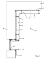
- the system 10 comprises an array of heat exchange panels 12 which in use are situated to form an integral layer of the walls W of the building, for example between a layer of inner leaf brickwork and interior plasterboard panels P or other such wall panels, or within the air filled cavity conventionally located between an inner and outer leaf of a wall, otherwise know as a cavity wall.
- the panels 12, as will be described in detail hereinafter, are adapted to extract heat from within a cavity C defined between the plasterboard P and the brickwork backing the plasterboard P, which heat has been transferred through the plasterboard P from an interior room of the building, in order to recover some of this heat and thus improve the thermal efficiency of the building.
- the panels 12 may be formed from any suitable material, and are preferable formed from a thermally conductive polymer which is relatively inexpensive, is lightweight in order to facilitate ease of installation, and can be moulded having a relatively thin profile in order to fit in the cavity C between the walls W and the plasterboard P.
- the panels 12 are secured in position within the cavity C via a plurality of stud type supports 14 which may be secured in position against the respective wall W by any suitable means, for example mechanical fixings, adhesive or the like.
- the supports 14 may also be secured to the floor F of the building, in order to allow a layer of the panels 12 to be located between the floor F and the floorboards B or equivalent floor covering such as to create a floating floor surface.
- the panels 12 would line the interior ground floor of a building, in addition to the entire surface area of the exterior walls and the roof or at least interior ceiling surfaces of the building. In this way the system 10 can create an essentially airtight envelope enclosing the interior working space of the building.
- the system 10 can both capture heat which would otherwise be lost through conduction through the surfaces of the building, as well as preventing heat loss through convection in the form of air flow from the interior to the exterior through gaps in the fabric of the building.
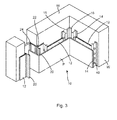
- FIG. 1 the system 10 is fitted within a corner formed by a pair of perpendicular outer walls W and the floor F.
- a corner joint 16 is secured at the interface between the two walls W and between each wall W and floor F.
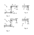
- the exact configuration of the corner joint 16 may be varied to suit the particular requirements of the corner in question, and a typical configuration is illustrated in section in Figure 4 .
- the corner joint 16 defines a pair of slots 18, each of which is adapted to receive the edge of a panel 12 therein. From here the respective panel 12 extends outwardly from the corner along the surface of the wall W a desired distance, which may depend on the dimensions of the panels 12 used.
- a plurality of the stud supports 14 are located at spaced intervals along the wall W with a single panel 12 extending between each adjacent pair of supports 14 as illustrated.
- a similar arrangement is employed along the floor F and roof (not shown) of the buildings.
- the supports 14 serve to both secure the panels 12 in position and to subsequently permit the mounting of conventional plasterboard panels P onto the outer face of the supports 14 thereby sandwiching the panels 12 between the plasterboard P and the wall W to form a composite building surface.
- the supports 14 space the plasterboard panels P away from the heat capture panels 12, a suitable or sufficient distance in order to allow conventional electrical or other hardware such as socket boxes, light switches, etc to be fitted into the plasterboard panels P without fouling the heat transfer panels 12 located behind.
- a return joint 20 is used in place of the interior corner joints 16.
- the return joint 20 again defines a mouth or channel 22 for receiving the respective edge of the panel 12.
- an ope stud 24 is provided at door and window returns.
- Sealing means is preferably provided between each of the channels 18, 22 and the panels 12. This may take the form of dedicated gaskets 26 located on the respective joint, or may be in the form of a bead of silicone/plastic or the like applied once the panel 12 has been seated in the respective joints. This allows a gas tight seal to be created at each corner/opening, enabling an essentially gas tight envelope to be established about the interior living space of the building to which the system 10 is fitted.
- each of the panels 12 defines, in the interior thereof, a fluid flow path defined by one or more channels 27 which may for example be circuitous is shape and defined by a regular array of baffles 28 which create a boustrophedonic fluid flow path extending between an inlet 30 and outlet 32 of the panel 12.
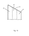
- the fluid flow path could be rectilinear and extend from one side of the panel 12 to an opposite side, such as from top to bottom, for example as shown in the alternative panel 12 illustrated in Figure 10 , in which three discrete flow paths defined by three channels 27 are provided.
- the inlet could be provided on one side and the outlet on the opposite side and thus at opposed ends of each of the channels 27.
- a manifold (not shown) may be secured to or formed integrally with the opposed edges of the panel 12, in which opposed manifolds the inlet and outlet are provided, in order to allow the fluid flow within each channel to be combined to enter/exit the panel 12 via a single inlet/outlet respectively.
- each channel 27 could be provided with a dedicated inlet and outlet. Regardless of the shape and/or orientation, the channel(s) 27 are fully enclosed within the panel 12, for the reasons set out hereinafter.
- the panel 12 comprises, in the embodiment illustrated, a pair of sections 34 joined via a central connector 36, and sealed at either end by end caps 38.
- This arrangement allows the height of the panel 12 to be varied by using more or less of the sections 34, adjacent sections 34 being connected together via the central connector 36. Fluid entering through the inlet 30 must pass down and up the height of the panel 12 around each of the baffles 28, thus maximising the fluid retention time within the panel 12, although as described above, the fluid flow through the panel 12 could be directly from top to bottom or from one lateral edge to the opposite.
- the panel 12 may be formed from a single section 34 whose dimensions are chosen to suit the intended application. However the use of multiple sections does provided greater flexibility in terms of allow the system 10 to be fitted to surfaces of various dimension. Individual sections 34 may also be cut to length in order to fit a particular location.
- Adjacent panels 12 of the system 10 are preferably connected in series, while the panel 12 at either end of the system 10 are then connected to either side of a heat exchange unit (not shown) such as to form a closed circuit between the array of panels 12 and the heat exchange unit.
- the inlet 30 of a first panel 12 is thus connected to a first side of the heat exchange unit, while the outlet 32 of a last panel 12 in the series is connected to a second side of the heat exchange unit in order to form a closed or sealed circuit.
- intermediate panels 12 may be connected directly to the heat exchange unit, and that more than one heat exchange unit may be employed depending on the dimensions and/or other requirements of the system 10, through the use of suitable piping/plumbing fixtures.
- the heat exchange units may be positioned in any suitable location, for example in an attic space of the building, a dedicated enclosure, or other existing location.
- Fluid for example a liquid or gas and preferably air
- Fluid is then pumped around this closed circuit from the heat exchange unit(s).
- Heat leaking through the plasterboard P from the interior of the building is then captured within the fluid being circulated through the panels 12 of the system 10, which heat is then extracted at the heat exchange unit (not shown).
- This heat may be re-circulated into the heating and/or ventilation system of the building, or may be used for any other purpose, for example supplementing a hot water supply of the building.
- the supports 14 are provided with apertures 40 therein through which connecting conduits (not shown) may be passed between adjacent panels 12.
- These apertures 14 may also be used to pass conventional services such as wiring, air conditioning, ducting, water/gas plumbing. Where each panel 12 includes a manifold at the inlet and/or outlet, it is then necessary for only a single connecting conduit (not shown) to be passed through the support 14 between adjacent panels 12.
- the system 110 comprises heat exchange panels 112 which are located about a building as described above with reference to the first embodiment, and preferably in conjunction with the panels 12 of the first embodiment, to facilitate the transfer of air into and out of the substantially air tight rooms created by the use of the system 10, as described in greater detail hereinafter.
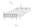
- Each panel 112 comprises an inner leaf 50 and an outer lead 52 in face to face thermal engagement with one another, each of which defines a circuitous flow path via the use of baffles 128 as described above with reference to the panel 12 of the first embodiment, although more simple edge to edge flow paths may also be employed as described above.
- the system 110 does not utilise a separate heat exchange unit to extract heat leaking from the interior of the building, but rather the panels 112 themselves form the heat exchange unit, as described below.
- warm air from the interior of a room is pumped from a first location into the inner leaf 50 at a first end or inlet 54, and passes circuitously or linearly through the panel 112 to exit via an outlet 56, which may be in fluid communication with the exterior of the building or the like.
- the outer leaf 52 is provided with an inlet 58, but at the same side of the panel 112 as the outlet 56 of the inner leaf 50.
- Cold air is drawn in from a second location such as the exterior of the building (or some other remote location), and pumped from the inlet 58, around the outer leaf 52, to exit at an outlet 60 on the same side as the inlet 54 of the inner leaf 50.
- the cold air from the exterior passes through the outer leaf 52 it extracts heat from the warm air passing through the inner leaf 50, thus warming the external fresh air before it is then pumped into the interior of the building via the outlet 60.
- the outside temperature is 10°C and the room temperature is 20°C
- both the incoming and exiting air will have a temperature of 15°C.
- the incoming fresh air will have reached approximately 20°C as it exits the panel 112 and enters the interior of the building while the exiting air will have exchanged a suitable quantity of its heat before being expelled from the panel 112 to the exterior of the building.
- the panel 112 forms both a heat exchange unit and a means of supplying fresh exterior air to the interior of the building, without losing heat from the interior of the building.
- the panels 112 are preferably placed in parallel to the panels 12 of the first embodiment, and are then utilised to effect the transfer of fresh air into the interior of the airtight envelope defined by the panels 12, without losing any of the heat contained within the building.
- a layer of insulation (not shown) is preferably provided around exterior of the panel 112.
- system 10, 110 of the present invention provides a simple yet effective means of capturing heat from within a building and re-using same as necessary in order to greatly improve the thermal efficiency of the building.
Landscapes
- Engineering & Computer Science (AREA)
- Architecture (AREA)
- Life Sciences & Earth Sciences (AREA)
- Mechanical Engineering (AREA)
- Sustainable Development (AREA)
- Civil Engineering (AREA)
- Structural Engineering (AREA)
- Building Environments (AREA)
Applications Claiming Priority (1)
| Application Number | Priority Date | Filing Date | Title |
|---|---|---|---|
| IE20100645 | 2010-10-07 |
Publications (1)
| Publication Number | Publication Date |
|---|---|
| EP2439353A2 true EP2439353A2 (de) | 2012-04-11 |
Family
ID=44720799
Family Applications (1)
| Application Number | Title | Priority Date | Filing Date |
|---|---|---|---|
| EP11184217A Withdrawn EP2439353A2 (de) | 2010-10-07 | 2011-10-06 | Wärmeerfassungssystem |
Country Status (1)
| Country | Link |
|---|---|
| EP (1) | EP2439353A2 (de) |
Cited By (2)
| Publication number | Priority date | Publication date | Assignee | Title |
|---|---|---|---|---|
| IT201700087608A1 (it) * | 2017-07-31 | 2019-01-31 | Cristiana Focone | Pannello modulare termoradiante |
| EP4403864A1 (de) * | 2023-01-20 | 2024-07-24 | Wise Open Foundation | Wärmetauscher, wärmetauschervorrichtung und verfahren zur montage von wärmetauschern |
-
2011
- 2011-10-06 EP EP11184217A patent/EP2439353A2/de not_active Withdrawn
Non-Patent Citations (1)
| Title |
|---|
| None |
Cited By (2)
| Publication number | Priority date | Publication date | Assignee | Title |
|---|---|---|---|---|
| IT201700087608A1 (it) * | 2017-07-31 | 2019-01-31 | Cristiana Focone | Pannello modulare termoradiante |
| EP4403864A1 (de) * | 2023-01-20 | 2024-07-24 | Wise Open Foundation | Wärmetauscher, wärmetauschervorrichtung und verfahren zur montage von wärmetauschern |
Similar Documents
| Publication | Publication Date | Title |
|---|---|---|
| RU2458286C2 (ru) | Модульная теплообменная система | |
| US20030084627A1 (en) | Utility distribution structure | |
| US9410706B2 (en) | Modular heating structure that can be fitted to the interior walls of buildings | |
| US12152800B2 (en) | Heat recovery ventilation unit | |
| EP2369254A2 (de) | Belüftungssystem | |
| CN102016477A (zh) | 用在建筑物中的中央热交换设施上的模块式热交换系统 | |
| CN103968700A (zh) | 一种高效换热水管以及热管辐射采暖/制冷系统 | |
| EP3910257A1 (de) | Von einem integrierten wind-photovoltaik-paneel gespeistes drahtloses lüftungssystem | |
| LT3350B (en) | Radiant or radiant-ventilating airconditioning prefabricated elements and air conditioning installation including said elements | |
| CN207829249U (zh) | 一种幕墙结构 | |
| KR101337337B1 (ko) | 조립식 냉,난방패널을 이용한 공조시스템 | |
| CN203893729U (zh) | 一种高效换热水管以及热管辐射采暖/制冷系统 | |
| US4307776A (en) | Heating method and apparatus | |
| EP2792962B1 (de) | Gehäuse zur Halterung von großflächigen Wärmetauscherplatten und die dazugehörige Lüftertechnik für die Montage an der Gebäudeaußenwand | |
| CN209082784U (zh) | 光伏幕墙 | |
| EP3018425A2 (de) | Wärmetausch-belüftungsvorrichtung | |
| JP2012063032A (ja) | 空調用地中熱利用装置 | |
| CN214154401U (zh) | 一种bipv组件以及由多个bipv组件组成的光伏阵列 | |
| CN219913440U (zh) | 一种基于开口型集成板的暖通一体化结构 | |
| CN100427703C (zh) | 一种具有空气调节功能的预制建筑隔板 | |
| SU1811573A3 (de) | ||
| US12480665B2 (en) | Heating/cooling walls and ceilings | |
| EP3450873B1 (de) | Luftzufuhrvorrichtung | |
| KR101461015B1 (ko) | 건물 환기용 외부공기 공급시스템 | |
| WO2019077640A1 (en) | MULTIFUNCTION MODULAR HOUSING |
Legal Events
| Date | Code | Title | Description |
|---|---|---|---|
| AK | Designated contracting states |
Kind code of ref document: A2 Designated state(s): AL AT BE BG CH CY CZ DE DK EE ES FI FR GB GR HR HU IE IS IT LI LT LU LV MC MK MT NL NO PL PT RO RS SE SI SK SM TR |
|
| AX | Request for extension of the european patent |
Extension state: BA ME |
|
| PUAI | Public reference made under article 153(3) epc to a published international application that has entered the european phase |
Free format text: ORIGINAL CODE: 0009012 |
|
| STAA | Information on the status of an ep patent application or granted ep patent |
Free format text: STATUS: THE APPLICATION IS DEEMED TO BE WITHDRAWN |
|
| 18D | Application deemed to be withdrawn |
Effective date: 20140501 |