EP2439471A2 - Procédé de changement d'huile de pompe à vide et appareil - Google Patents
Procédé de changement d'huile de pompe à vide et appareil Download PDFInfo
- Publication number
- EP2439471A2 EP2439471A2 EP11179696A EP11179696A EP2439471A2 EP 2439471 A2 EP2439471 A2 EP 2439471A2 EP 11179696 A EP11179696 A EP 11179696A EP 11179696 A EP11179696 A EP 11179696A EP 2439471 A2 EP2439471 A2 EP 2439471A2
- Authority
- EP
- European Patent Office
- Prior art keywords
- refrigerant
- oil
- processing equipment
- fluid
- valve
- Prior art date
- Legal status (The legal status is an assumption and is not a legal conclusion. Google has not performed a legal analysis and makes no representation as to the accuracy of the status listed.)
- Ceased
Links
Images


Classifications
-
- F—MECHANICAL ENGINEERING; LIGHTING; HEATING; WEAPONS; BLASTING
- F25—REFRIGERATION OR COOLING; COMBINED HEATING AND REFRIGERATION SYSTEMS; HEAT PUMP SYSTEMS; MANUFACTURE OR STORAGE OF ICE; LIQUEFACTION SOLIDIFICATION OF GASES
- F25B—REFRIGERATION MACHINES, PLANTS OR SYSTEMS; COMBINED HEATING AND REFRIGERATION SYSTEMS; HEAT PUMP SYSTEMS
- F25B45/00—Arrangements for charging or discharging refrigerant
-
- B—PERFORMING OPERATIONS; TRANSPORTING
- B60—VEHICLES IN GENERAL
- B60H—ARRANGEMENTS OF HEATING, COOLING, VENTILATING OR OTHER AIR-TREATING DEVICES SPECIALLY ADAPTED FOR PASSENGER OR GOODS SPACES OF VEHICLES
- B60H1/00—Heating, cooling or ventilating devices
- B60H1/00507—Details, e.g. mounting arrangements, desaeration devices
- B60H1/00585—Means for monitoring, testing or servicing the air-conditioning
-
- F—MECHANICAL ENGINEERING; LIGHTING; HEATING; WEAPONS; BLASTING
- F25—REFRIGERATION OR COOLING; COMBINED HEATING AND REFRIGERATION SYSTEMS; HEAT PUMP SYSTEMS; MANUFACTURE OR STORAGE OF ICE; LIQUEFACTION SOLIDIFICATION OF GASES
- F25B—REFRIGERATION MACHINES, PLANTS OR SYSTEMS; COMBINED HEATING AND REFRIGERATION SYSTEMS; HEAT PUMP SYSTEMS
- F25B2345/00—Details for charging or discharging refrigerants; Service stations therefor
- F25B2345/002—Collecting refrigerant from a cycle
Definitions
- the disclosure generally relates to equipment for servicing automotive vehicle air conditioning systems, and more particularly to clearing oil from a vacuum pump in a refrigerant recovery unit used to service a vehicle.
- Portable refrigerant recovery units or carts are used in connection with the service and maintenance of refrigeration systems including an automotive vehicle's air conditioning system.
- the refrigerant recovery unit connects to the air conditioning system of the automotive vehicle to recover refrigerant out of the system, separate out oil and contaminants, and recharge the system with additional refrigerant.
- An oil inject portion of the refrigerant recovery unit is used to put the same amount of compressor oil back into the air conditioning system as was taken out during the recovery process. This may be a visual determination by reading a graduation on the oil drain bottle and on the oil inject bottle, or it may be an automated process.
- the oil required in the air conditioning system of a conventional automotive vehicle typically differs from the oil required in a hybrid vehicle.
- Conventional automotive air conditioning systems typically use polyalkylene glycol lubricant (“PAG”) oil as the refrigerant lubricant or compressor oil, whereas many hybrid vehicle systems use polyolester (“POE”) oil.
- PAG polyalkylene glycol lubricant
- POE polyolester
- Portable refrigerant recovery units or carts used in connection with the service and maintenance of refrigeration systems often have vacuum pumps to create a vacuum in order to draw refrigerant from a vehicle's air conditioning system.
- the vacuum pump itself may be lubricated with lubricating oil.
- the lubricating oil may need to be changed from time to time.
- Common vacuum pumps have an oil drain plug that is removed in order to drain the vacuum pump oil. Then the person performing the oil change locates a container to drain the oil into. On some pieces of air conditioning servicing equipment, there is no place to set the container so a person must hold the container while the oil is draining. Having a person hold the oil container can lead to spills related to human err and require the time of the holder. A system that automates the oil draining process may be desired.
- refrigerant processing equipment may include: a vacuum pump; an outlet for draining vacuum pump lubricating oil from the vacuum pump; a fluid container; and a conduit configured to provide a fluid connection between the outlet and the container.
- a method for draining oil from a vacuum pump from refrigerant processing equipment is provided.
- refrigerant processing equipment may be provided.
- the refrigerant processing equipment may include; means for creating a vacuum; means for outleting a means for lubricating the means for creating a vacuum; means for storing a fluid; and means for transmitting a fluid configured to provide a fluid connection between the outletting means and the means for storing a fluid.
- a method for draining oil from a vacuum pump from refrigerant processing equipment may include connecting an outlet for oil on the vacuum pump with a container; and providing a valve between the outlet and the container to selectively provide fluid communication between the outlet and an the container.
- FIG. 1 is a fragmentary front plan view of an example refrigerant recovery unit shown with a portion of the front cover removed.
- FIG. 2 is a fragmentary rear plan view of the refrigerant recovery unit shown in FIG. 1 according to an embodiment of the invention.
- FIG. 3 is an example of a flow diagram of the refrigerant recovery unit shown in FIGS. 1 and 2 .
- FIG. 4 is another example of a flow diagram of the refrigerant recovery unit shown in FIGS. 1 and 2 .
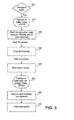
- FIG. 5 is a flow chart illustrating operations that may be performed by the refrigerant recovery cart unit according to an embodiment of the invention.
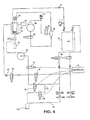
- FIG. 6 is an example of a flow diagram of a refrigerant recovery unit having an automated vacuum pump oil draining apparatus.
- FIGS. 1 and 2 show an example of a portable refrigerant recovery unit 10 constructed according to principles of the invention, for recovering and recycling refrigerant from a refrigerant system, such as in an automotive vehicle.
- the recovery unit 10 includes a flushable oil inject circuit for removing traces of one kind of oil so that the unit 10 may service the another vehicle utilizing a different kind of oil.
- the refrigerant recovery unit 10 is a machine having a cabinet 20 supported by a pair of wheels 22, for portability.
- the unit 10 includes a first container or main tank 12 for holding a primary supply of refrigerant.
- the main tank 12 may also be referred to as an internal storage vessel (ISV).
- the primary supply of refrigerant or recovered refrigerant contains refrigerant that has been recovered from the air conditioning system.
- the unit 10 also includes a second container or auxiliary tank 14 for holding a secondary supply of refrigerant.
- the secondary supply of refrigerant has a known chemical composition, and is sometimes referred to as fresh refrigerant, virgin refrigerant or recharging refrigerant.
- the auxiliary tank 14 is arranged to be in fluid communication with the main tank 12 so that fresh refrigerant can be transferred from the auxiliary tank 14 to the main tank 12 as needed.
- An electronic controller 16 includes a microprocessor on a circuit board 17.
- the electronic controller 16 controls the transfer of refrigerant from the auxiliary tank 14 to the main tank 12 and between the main tank 12 and a refrigeration system 74 ( FIG. 3 ).
- the controller 16 also controls electromechanical solenoid valves, including solenoid valves 76, 96, 100 ( FIG. 3 ). Although only three solenoid valves are shown connected to the controller, in some embodiments each of the solenoid valves may be connected to the controller.
- the controller 16 may include a memory unit to store software and data, and the microprocessor may be coupled to the memory unit for executing the software stored in the memory unit.
- the electronic controller 16 receives data signals from a variety of devices and sensors, including pressure sensors, temperature sensors, control switches (on the control panel 32), and a weighing device 34.
- the weighing device 34 shown in the example embodiment is a load cell, but the weighing device may also be any type of electronic scale or any other type of weighing device configurable to transmit a weight data signal to the controller 16. As shown in FIG. 2 , the main tank 12 rests on the weighing device 34. The weighing device 34 provides a weight data signal to the controller 16 such that the weight of the tank comprising its tare weight plus the weight of refrigerant therein is monitored by the controller 16.
- the control panel 32 includes an on/off switch 35 and a display 36 for displaying the operational status of the refrigerant recovery unit's operation.
- the display may be an LCD display or other suitable electronic display that is coupled to the controller 16 by way of a conventional input/output circuit.
- the control panel 32 further includes a switch panel 38 having a conventional keyboard 40, and a plurality of push-button switches 42 for controlling the operation of the unit 10 through its various phases of operation and/or for selecting parameters for display.
- the keyboard 40 in conjunction with operational switches 42 and display 36 allow an operator to enter the desired operational parameters for the unit 10 according to manufacturer specifications for the servicing of an air conditioning system in a particular vehicle.
- the refrigerant recovery unit 10 includes a high pressure hose 24, typically color coded red, with a coupling 26 for coupling to the high pressure port of an automotive vehicle refrigeration system and a low pressure hose 28, typically color coded blue, having a coupling 30 for coupling to the low pressure port.
- a high pressure hose 24 typically color coded red
- a low pressure hose 28 typically color coded blue
- the refrigerant recovery unit may be configured with one hose, in accordance with the principles of the invention.
- the front panel of the cabinet 20 is shown broken away in FIG. 1 to show the major elements of the refrigerant recovery unit 10.
- the input hoses 24 and 28 are coupled to pressure gauges 44 and 46, respectively, which are mounted on the front panel of refrigerant recovery unit 10, as seen in FIG. 1 .
- electrical pressure transducers may be coupled to the hoses 24 and 28, and to the controller 16 through conventional input/output circuits to provide the controller 16 with pressure information during operation of the unit 10.
- Gauges 44 and 46 provide the operator with a conventional analog or digital display of the pressure.
- a fluid compressing means or compressor 56 and a vacuum pump 58 Behind the front of cabinet 20 on floor 54, is mounted the main tank 12 of refrigerant ( FIG. 2 ) for the supply of refrigerant to the system being serviced. Also, mounted adjacent the main tank 12 is the auxiliary supply tank 14 which supplies additional refrigerant to the main tank 12. High pressure hoses and connectors together with control valves couple tank 14 to tank 12.
- an oil separator 62 mounted to the inside of rear wall 60 of cabinet 20 is an oil separator 62 and a compressor oil separator filter 64.
- a fresh oil canister 70 is mounted within a side compartment of cabinet 20.
- a recovery or waste oil container 72 is mounted on the lower part of the cabinet 20 to receive oil drained from the oil separator 62.
- hoses 24 and 28 ( FIG. 1 ) are coupled to the refrigeration system 74 of a vehicle, and the recovery cycle is initiated by the opening of high pressure and low pressure solenoids 76, 78, respectively.
- This allows the refrigerant within the refrigeration system 74 to flow through a recovery valve 80 and a check valve 82.
- the refrigerant flows from the check valve 82 into a system oil separator 62, where it travels through a filter/dryer 64, to an input of a compressor 56.
- Refrigerant is drawn through the compressor 56 through a normal discharge solenoid 84 and through the compressor oil separator 86, which circulates oil back to the compressor 56 through an oil return valve 88.
- the refrigerant recovery unit 10 includes a high pressure switch 90 in communication with the controller 16, which is programmed to determine an upper pressure limit, for example, 435 psi, to shut down the compressor 56 to protect the compressor 56 from excessive pressure, although this feature is optional. If a purging of the system is desired, a high-side clear solenoid (not shown) may optionally be coupled to the output of the compressor 56 to release the recovered refrigerant transferred from compressor 56 directly into the main tank 12, instead of through a path through the normal discharge solenoid 84.
- the heated compressed refrigerant exits the oil separator 86 and then travels through a loop of conduit or heat exchanger 91 for cooling or condensing.
- a switch or transducer 92 Coupled to the system oil separator 62 is a switch or transducer 92, such as a low pressure switch or pressure transducer, for example, that senses pressure information, and provides an output signal to the microprocessor through a suitable interface circuit programmed to detect when the pressure has recovered the refrigerant down to 13 inches of mercury, for example.
- the recovered refrigerant flows through a normal discharge check valve 94 and into the main tank 12.
- the evacuation cycle begins by the opening of high pressure and low pressure solenoids 76 and 78 and valve 96, leading to the input of a vacuum pump 58.
- an air intake valve (not shown) is opened, allowing the vacuum pump 58 to start up exhausting air.
- the vehicle system 74 is then evacuated by the closing of the air intake valve and the opening of valve 96, allowing the vacuum pump 58 to exhaust any trace gases remaining until the pressure is approximately 29 inches of mercury, for example.
- the controller 16 actuates valve 96 by turning it off and beginning the recharging cycle.
- the recharging cycle begins by opening charge valve 98 to allow the liquid refrigerant in tank 12, which is at a pressure of approximately 70 psi or above, to flow through the high side of the refrigeration system 74.
- the flow is through charge valve 98 for a period of time programmed to provide a full charge of refrigerant to the vehicle.
- the refrigerant recovery unit 10 recovers refrigerant out of the refrigeration system 74, and separates out compressor oil and contaminants, and recharges the system with additional refrigerant.
- the compressor oil recovered out of the refrigeration system 74 lubricates the compressor and needs to be replaced back into the system 74.
- PAG oil is typically used as the refrigerant lubricant or compressor oil.
- Many hybrid systems with electric compressors use a different kind of oil, known as POE oil.
- the POE systems are sensitive to an electrical resistivity of the lubricant, because the lubricant contacts the electrical system.
- PAG oils typically have a lower resistivity than that of the POE oils, and this lower resistivity can create a potentially damaging leakage current. More particularly, for a given voltage, such as 300 volts which is approximately the operating voltage for a hybrid system, the lower resistivity translates into a high leakage current. Thus, if a certain percentage of the PAG oil gets into the hybrid system, the lower resistivity of the PAG oil and the resulting leakage current can cause electrical problems in the hybrid system.
- an apparatus and method are developed to clear oil of one type out of the refrigerant recovery unit 10 and to prepare the unit 10 to switch over to a new type of oil so that a different vehicle requiring the new type of oil may be serviced with the same unit.
- an oil inject means for adding oil into the system 74.
- an oil inject means is the an oil inject circuit. More particularly, the oil inject circuit may be arranged in fluid communication with the vacuum pump 58 of the recovery circuit.
- the oil inject circuit includes an oil inject valve 100 and an oil inject hose or line 112.
- the oil inject hose 112 is one example of a fluid transportation means for transmitting oil to the refrigerant recovery circuit of the refrigerant recovery unit 10.
- the oil inject hose 112 may be one length of hose or multiple lengths of hose or tubing or any other suitable means for transporting fluid.
- the oil inject hose 112 connects on one end to an oil inject bottle 114 and on the other end couples to the refrigerant recovery circuit.
- the oil inject circuit couples to the recovery circuit by way of the oil inject hose between the high side solenoid 76 and the high side inlet 116. Disposed along the length of the oil inject hose is the oil inject valve 100.
- the oil inject valve 100 is preferably a solenoid actuated valve arranged in electrical communication with the controller 16 and configured to open and close when a corresponding signal from the controller 16 is received.
- the oil inject path follows from the oil inject bottle 114, though the oil inject solenoid 100, to the junction with the high side charge line, and to the refrigerant system 74.
- the oil inject bottle 114 is removed. With the oil inject bottle detached from the oil inject circuit, the end of the oil inject hose 112 that was connected to the oil inject bottle 114 is opened up to the air. Exposing the oil inject hose 112 to atmospheric pressure aides in permitting airflow through the hose, as will be discussed in more detail below.
- the oil inject solenoid 100, the high side inlet solenoid 76, and the vacuum solenoid 96 are opened.
- the solenoid valves are actuated by the controller 16 which operates to send communication to each of the valves to open them.
- the vacuum pump 58 With the oil inject bottle removed and the valves open, the vacuum pump 58 is turned on to generate airflow through the oil inject hose 112 and remove oil from the oil inject circuit.
- the pumping of the vacuum pump 58 generates enough velocity or airspeed to blow the compressor oil out of the oil inject circuit and deposit it into the waste oil drain bottle 72.
- the pumping continues for a length of time sufficient to flush out a desired percentage of the oil out of the oil inject circuit.
- the amount of time selected for running the vacuum pump may be a predetermined time such as 25 seconds that is built-in to the software program running on the refrigerant recovery cart 10 or it may any other length of time chosen to achieve the desired result.
- the vacuum pump 58 is operated for 15 seconds, then the oil inject solenoid 100 is closed to further evacuate the path between the vacuum pump 58 and the oil inject solenoid 100.
- the pump 58 continues, for example, 10 more seconds, then the high side inlet solenoid 76 and the vacuum solenoid 96 are closed. At this point, the vacuum pump 58 is stopped.
- a new oil inject bottle 114 containing the appropriate type of oil for the next vehicle to be serviced may be installed on the refrigerant recovery unit 10. Since the oil inject hose 112 will be full of air from having operated the vacuum pump 58, a small amount of oil may be injected back into the circuit to purge the hose 112 of any air and small amounts of the old oil that may be left in the line.
- the service hoses 24, 28 may optionally be flushed with refrigerant to remove oil remaining in the high side service hose 24.
- One such method for flushing the services hoses 24, 28 of the refrigerant recovery unit 10 is described in U.S. Serial No. 12/248,352 incorporated herein in its entirety.
- a quantity of refrigerant is used to clean out the oil inject circuit.
- the oil inject circuit may modified so that a service hose, such as the high side service hose 24, may be coupled in fluid communication with the oil inject line 112 so that refrigerant may be used to flush out any oil remaining in the oil inject circuit.
- the high side service hose is coupled to the end of the oil inject tube that connects to the oil inject bottle so that refrigerant may be flushed through the oil inject path from beginning to end.
- the process for clearing oil from the oil inject circuit using refrigerant begins by opening the high side charge solenoid 98, the oil inject solenoid 100, and the recover solenoid 80.
- refrigerant may be transferred from the primary supply tank 12 through the high side charge solenoid 98 to the high side inlet of the refrigerant recovery unit 10, through the high side service hose 24 and into the oil inject circuit.
- the refrigerant As the refrigerant is received into the oil inject circuit, it pushes the oil through the oil inject circuit and through the refrigerant recovery circuit.
- the refrigerant and oil cycles through the normal refrigerant recovery circuit for recovering refrigerant into the primary supply tank 12 including separating out oil into the waste oil container 72, as described above.
- the high side service hose 24 is disconnected from the oil inject circuit. If desired, this method may also be followed by a flushing of the refrigerant recovery unit service hoses, as previously discussed.
- Example operations that may be performed by the refrigerant recovery unit 10 to flush the oil from the oil inject circuit in connection with the embodiment illustrated in FIG. 3 will next be described.
- the software program begins at operation 200 with a prompt to a user asking if it is desired to change the oil type. If YES is selected, the program then prompts the user to remove the oil inject bottle and to press the START button, as indicated by operation 210.
- the controller 16 turns on the vacuum pump 58, and opens the vacuum solenoid 96, the high side inlet solenoid 76 and the oil inject solenoid 100, as indicated by operation 220.
- the vacuum pump is operated for a period of time, for example, 15 seconds. It is to be understood that the process is not limited to a period of 15 seconds but that any time between 2 seconds to 30 seconds is also contemplated. Any period of time sufficient clear the lines of residual oil may be used.
- the controller 16 acts to close each of the solenoids. Initially, only the oil inject solenoid 100 is closed so that the path between the vacuum pump 58 and the oil inject line may be further evacuated. With the oil inject solenoid 100 closed, the vacuum pump 58 continues to pump for some additional period of time, for example, 10 additional seconds, or until substantially all of the air is pumped out of the lines. Then, the vacuum solenoid 96 and the high side inlet solenoid 76 are closed, as indicated in operation 230. After, each of the solenoids are closed, the controller 16 stops the vacuum pump, as indicated at operation 240.
- the controller 16 operates to open the oil inject solenoid 100, as indicated at operation 260.
- the oil inject solenoid 100 is opened for a period of time sufficient to fill the high side line with the new oil type, for example, a period of 5 seconds.
- the controller 16 operates to flush refrigerant through the oil inject circuit, using the hose flush routine disclosed and described in U.S. Serial No. 12/248,352 discussed above, as indicated at operation 270.
- the steps discussed herein can be automated through the use of a software program.
- FIG. 6 illustrates a schematic circuit diagram of the refrigerant handing or servicing equipment in accordance with some embodiments of the invention.
- the diagram shown in FIG. 6 is similar to those shown in FIGS. 3 and 4 and described above.
- Features of FIG. 6 having common reference numbers as the features shown in FIGS. 3 and 4 are substantially similar and will not be again described.
- Features in FIG. 6 identified by reference numbers starting with 300 (and higher numbers) are peculiar to FIG. 6 and will be described in detail below.
- a vacuum pump oil drain apparatus 300 is shown in FIG. 6 .
- the vacuum pump oil drain apparatus 300 includes a vacuum pump oil drain valve 302 that is located along a vacuum pump oil drain conduit 304 connecting a vacuum pump oil drain outlet 306 to a container 72 for containing the drained vacuum pump oil.
- the vacuum pump oil drain valve 302 may be an electronically activated solenoid valve 302. In other embodiments the valve 302 may be a manually activated valve 302 and manually actuated by a user.
- the conduit 304 may be a flexible hose or any other suitable conduit for provided fluid communication between the outlet 306 and the container 72.
- the container 72 is the used refrigerant oil drain bottle 72 already present in the refrigerant process equipment. In other embodiments, other containers 72 may be used.
- valve 302 may be operatively connected to the controller 16.
- the connection 303 may be a wireless or wired connection.
- the controller 16 may be configured to allow a user to initiate a change vacuum pump oil sequence. When a user initiates a change vacuum pump oil routine, the controller 16 may check to ensure that the container 72 is not already full so that the vacuum pump oil may be drained. The controller 16 may check the status of the container by using a sensor or may determine if another routine is being run that would cause fluid to be in the container 72. If the container 72 in not available to contain vacuum pump oil, the controller may display an error message and not actuate the valve 302 to drain the vacuum pump oil.
- the controller may send a signal to the valve 302 to open the valve causing the lubricating oil to drain through the conduit 304, through the valve 302 into the container 72.
- the valve 302 may be held open for a period of time, or in other embodiments, the valve 302 may remain open until some other action occurs such as a user imputing a command to the controller 16 to close the valve.
- the valve 302 is kept in the closed position.
- the air purging apparatus 308 allows the system to be purged of air. Air purged from the system may exit the main tank 12, through and orifice 312, through a purging valve 314 and through an air diffuser 316. In some embodiments the orifice may be 0.028 of an inch.
- a pressure transducer 310 may measure the pressure contained within the purge apparatus 308. The valve 314 may be selectively actuated to permit or not permit the purging apparatus 308 to be open to the ambient conditions.
- High side clearing valves 218 may be used to clear out part of the high pressure side of the system.
- the high side clearing valves may include valve 322 and check valve 320.
- Valve 322 may be a solenoid valve. When it is desired to clear part of the high side, valve 322 is opened. Operation of the compressor 56 will force refrigerant out of part of the high pressure side through valves 322 and 320 and into the main tank 12. During this procedure the normal discharge valve 84 may be closed.
- a deep recovery valve 324 is provided to assist in the deep recovery of refrigerant.
- the remaining refrigerant may be extracted from the automotive recovery system by opening the deep recovery valve 324 and turning on the vacuum pump 58.
- the power charge valve 326 When charging a vehicle's AC system, the power charge valve 326 may be opened.
- the recovery unit 10 may also be able to add refrigerant to a vehicle AC system that may be low on refrigerant.
- the unit 10 may include tank fill structure 332, and valves 330 and 328.
- the tank fill structure 332 may be configured to attach to a refrigerant source.
- the valve 330 may be a solenoid valve and the valve 328 may be a check valve. In other embodiments valve 330 may be a manually operated valve. When it is desired to allow refrigerant from a refrigerant source to enter the unit 10 the tank fill structure 332 is attached to the refrigerant source and the tank fill valve 330 is opened.
- the check valve 328 prevents refrigerant from the unit 10 from flowing out of the unit through the tank fill structure 332.
- the tank fill valve 330 is kept closed.
- the tank fill valve 330 may be connected to and controlled by the controller 16.
- any or all of the electronic solenoid or electrically activated valves may be connected and controlled by the controller 16.
Landscapes
- Engineering & Computer Science (AREA)
- Physics & Mathematics (AREA)
- Mechanical Engineering (AREA)
- Thermal Sciences (AREA)
- General Engineering & Computer Science (AREA)
- Loading And Unloading Of Fuel Tanks Or Ships (AREA)
- Jet Pumps And Other Pumps (AREA)
Applications Claiming Priority (1)
| Application Number | Priority Date | Filing Date | Title |
|---|---|---|---|
| US12/898,299 US8590321B2 (en) | 2010-10-05 | 2010-10-05 | Vacuum pump oil changing method and apparatus |
Publications (2)
| Publication Number | Publication Date |
|---|---|
| EP2439471A2 true EP2439471A2 (fr) | 2012-04-11 |
| EP2439471A3 EP2439471A3 (fr) | 2013-01-16 |
Family
ID=44677589
Family Applications (1)
| Application Number | Title | Priority Date | Filing Date |
|---|---|---|---|
| EP11179696A Ceased EP2439471A3 (fr) | 2010-10-05 | 2011-09-01 | Procédé de changement d'huile de pompe à vide et appareil |
Country Status (2)
| Country | Link |
|---|---|
| US (1) | US8590321B2 (fr) |
| EP (1) | EP2439471A3 (fr) |
Cited By (2)
| Publication number | Priority date | Publication date | Assignee | Title |
|---|---|---|---|---|
| EP2924374A1 (fr) * | 2014-03-21 | 2015-09-30 | Robert Bosch GmbH | Système et procédé de récupération de réfrigérant |
| EP4321757A3 (fr) * | 2022-08-11 | 2024-02-28 | Dometic Sweden AB | Adaptateur d'entretien de pompe à vide, unité de service pour un système de climatisation de véhicule et procédé d'entretien d'une pompe à vide d'une unité de service |
Families Citing this family (6)
| Publication number | Priority date | Publication date | Assignee | Title |
|---|---|---|---|---|
| WO2011088831A1 (fr) * | 2010-01-22 | 2011-07-28 | Agramkow Fluid Systems A/S | Système et procédé de rinçage de systèmes de climatisation |
| WO2015164725A1 (fr) * | 2014-04-24 | 2015-10-29 | Robert Bosch Gmbh | Système et procédé pour injecter de l'huile dans un circuit de climatisation |
| JP6050855B2 (ja) * | 2015-04-13 | 2016-12-21 | 株式会社岡常歯車製作所 | 流体回収再生充填装置及び流体回収再生充填方法 |
| US10627142B2 (en) * | 2016-10-27 | 2020-04-21 | Bosch Automotive Service Solutions Inc. | Apparatus and method for determining the quantity of dissolved refrigerant in oil recovered from an air conditioning system |
| CN107720678A (zh) * | 2017-10-25 | 2018-02-23 | 湖北省电力装备有限公司 | 一种中央空调专用电动加油泵 |
| US12523401B2 (en) | 2023-06-09 | 2026-01-13 | Trane International Inc. | Refrigerant recovery system and recovery cart thereof |
Citations (1)
| Publication number | Priority date | Publication date | Assignee | Title |
|---|---|---|---|---|
| JPS6223594A (ja) * | 1985-07-23 | 1987-01-31 | Dengen Kk | 冷凍空調機用真空ポンプ |
Family Cites Families (26)
| Publication number | Priority date | Publication date | Assignee | Title |
|---|---|---|---|---|
| US4285206A (en) * | 1979-02-05 | 1981-08-25 | Draf Tool Co., Inc. | Automatic refrigerant recovery, purification and recharge apparatus |
| US4364236A (en) * | 1980-12-01 | 1982-12-21 | Robinair Manufacturing Corporation | Refrigerant recovery and recharging system |
| US4441330A (en) * | 1980-12-01 | 1984-04-10 | Robinair Manufacturing Corporation | Refrigerant recovery and recharging system |
| US4676265A (en) * | 1981-03-18 | 1987-06-30 | Volk Kenneth J | Vacuum pump drain device |
| USRE33212E (en) * | 1985-04-29 | 1990-05-08 | Kent-Moore Corporation | Service station for refrigeration equipment |
| US4688388A (en) | 1985-04-29 | 1987-08-25 | Kent-Moore Corporation | Service station for refrigeration equipment |
| US4755957A (en) * | 1986-03-27 | 1988-07-05 | K-White Tools, Incorporated | Automotive air-conditioning servicing system and method |
| US5033271A (en) * | 1987-11-04 | 1991-07-23 | Kent-Moore Corporation | Refrigerant recovery and purification system |
| US5172562A (en) * | 1990-07-20 | 1992-12-22 | Spx Corporation | Refrigerant recovery, purification and recharging system and method |
| US5560215A (en) | 1992-05-14 | 1996-10-01 | Talarico; Angelo | Gas processor |
| US5287589A (en) * | 1992-08-31 | 1994-02-22 | Container Products Corp. | Self-contained cleaning and retrieval apparatus |
| US5325675A (en) * | 1993-08-02 | 1994-07-05 | Spx Corporation | Refrigerant handling system and method with enhanced recovery vacuum capability |
| US5606862A (en) * | 1996-01-18 | 1997-03-04 | National Refrigeration Products | Combined refrigerant recovery, evacuation and recharging apparatus and method |
| US5758506A (en) * | 1996-07-03 | 1998-06-02 | White Industries, Llc | Method and apparatus for servicing automotive refrigeration systems |
| DE69924229T2 (de) * | 1998-07-22 | 2006-03-30 | Snap-On Tools Co., Kenosha | Kupplungsanordnung |
| US6206055B1 (en) * | 1998-10-08 | 2001-03-27 | Peter C. Hollub | Apparatus and method for removing and replacing vehicle hydraulic fluid |
| US6315524B1 (en) * | 1999-03-22 | 2001-11-13 | David Muhs | Pump system with vacuum source |
| US6314749B1 (en) * | 2000-02-03 | 2001-11-13 | Leon R. Van Steenburgh, Jr. | Self-clearing vacuum pump with external cooling for evacuating refrigerant storage devices and systems |
| US6217328B1 (en) * | 2000-02-07 | 2001-04-17 | William L. Oliver | Oral hygiene system |
| CA2431298A1 (fr) * | 2002-06-11 | 2003-12-11 | Tecumseh Products Company | Methode de drainage et de remplissage d'un compresseur a huile hermetique |
| US6619065B1 (en) * | 2002-11-01 | 2003-09-16 | Bruce H. Burton | Heating ventilating and air conditioning worker's servicing cart |
| US6854281B1 (en) * | 2003-08-19 | 2005-02-15 | He Jhang Environmental Technology Co., Ltd. | Check device for an air conditioning system of an automobile and an air conditioner compressor |
| ITMI20072100A1 (it) * | 2007-10-31 | 2009-05-01 | Parker Hannifin Spa | Dispositivo di accumulo refrigerante e recupero olio per sistemi di recupero/rigenerazione/ricarica di un fluido refrigerante |
| US8272228B2 (en) | 2008-01-29 | 2012-09-25 | Spx Corporation | Apparatus to clear oil from the hoses and front end of a recovery recharge machine |
| US7937957B2 (en) | 2008-05-05 | 2011-05-10 | Spx Corporation | Method for using high pressure refrigerant for leak checking a system |
| US9080569B2 (en) | 2009-01-22 | 2015-07-14 | Gregory S. Sundheim | Portable, rotary vane vacuum pump with automatic vacuum breaking arrangement |
-
2010
- 2010-10-05 US US12/898,299 patent/US8590321B2/en not_active Expired - Fee Related
-
2011
- 2011-09-01 EP EP11179696A patent/EP2439471A3/fr not_active Ceased
Patent Citations (1)
| Publication number | Priority date | Publication date | Assignee | Title |
|---|---|---|---|---|
| JPS6223594A (ja) * | 1985-07-23 | 1987-01-31 | Dengen Kk | 冷凍空調機用真空ポンプ |
Cited By (3)
| Publication number | Priority date | Publication date | Assignee | Title |
|---|---|---|---|---|
| EP2924374A1 (fr) * | 2014-03-21 | 2015-09-30 | Robert Bosch GmbH | Système et procédé de récupération de réfrigérant |
| US9732999B2 (en) | 2014-03-21 | 2017-08-15 | Bosch Automotive Service Solutions Inc. | System and method for recovering refrigerant |
| EP4321757A3 (fr) * | 2022-08-11 | 2024-02-28 | Dometic Sweden AB | Adaptateur d'entretien de pompe à vide, unité de service pour un système de climatisation de véhicule et procédé d'entretien d'une pompe à vide d'une unité de service |
Also Published As
| Publication number | Publication date |
|---|---|
| US8590321B2 (en) | 2013-11-26 |
| US20120079839A1 (en) | 2012-04-05 |
| EP2439471A3 (fr) | 2013-01-16 |
Similar Documents
| Publication | Publication Date | Title |
|---|---|---|
| US8122731B2 (en) | Method and apparatus for clearing oil inject circuit for changing oil types | |
| US8590321B2 (en) | Vacuum pump oil changing method and apparatus | |
| US8572992B2 (en) | Method for recovery and recharge of blend refrigerants with blend sent for reclamation | |
| US8616011B2 (en) | Internal clearing function for a refrigerant recovery/recharge machine | |
| US8661839B2 (en) | Background tank fill based on refrigerant composition | |
| US6134896A (en) | Background tank fill | |
| US8079226B2 (en) | Method for accurately recharging A/C systems | |
| EP2525205A1 (fr) | Procédé de vérification des fuites de dégradation de pression et appareil | |
| US7937957B2 (en) | Method for using high pressure refrigerant for leak checking a system | |
| EP2591929B1 (fr) | Appareil et procédé permettant d'identifier et d'exploiter la purge d'air dans un mode sécurisé et présentant un tube plongeur | |
| CN104487789B (zh) | 用于致冷剂回收单元的致冷剂转换套件和方法 | |
| US20060130510A1 (en) | Modular recovery apparatus and method | |
| US6138462A (en) | Refrigerant recovery and recharging system with automatic oil drain | |
| EP2815192B1 (fr) | Procédé et appareil d'amélioration de la précision d'essais de diagnostic d'air climatisé | |
| EP2938937A1 (fr) | Dispositif et procédé de retrait de réfrigérant | |
| US9470443B2 (en) | Modified hose flush device and method | |
| US9447998B2 (en) | Method and apparatus for improving the charge accuracy of a refrigerant recovery unit |
Legal Events
| Date | Code | Title | Description |
|---|---|---|---|
| AK | Designated contracting states |
Kind code of ref document: A2 Designated state(s): AL AT BE BG CH CY CZ DE DK EE ES FI FR GB GR HR HU IE IS IT LI LT LU LV MC MK MT NL NO PL PT RO RS SE SI SK SM TR |
|
| AX | Request for extension of the european patent |
Extension state: BA ME |
|
| PUAI | Public reference made under article 153(3) epc to a published international application that has entered the european phase |
Free format text: ORIGINAL CODE: 0009012 |
|
| RIC1 | Information provided on ipc code assigned before grant |
Ipc: F25B 43/02 20060101AFI20120914BHEP Ipc: B60H 1/00 20060101ALI20120914BHEP Ipc: F25B 45/00 20060101ALI20120914BHEP |
|
| PUAL | Search report despatched |
Free format text: ORIGINAL CODE: 0009013 |
|
| AK | Designated contracting states |
Kind code of ref document: A3 Designated state(s): AL AT BE BG CH CY CZ DE DK EE ES FI FR GB GR HR HU IE IS IT LI LT LU LV MC MK MT NL NO PL PT RO RS SE SI SK SM TR |
|
| AX | Request for extension of the european patent |
Extension state: BA ME |
|
| RIC1 | Information provided on ipc code assigned before grant |
Ipc: F25B 45/00 20060101ALI20121210BHEP Ipc: F25B 43/02 20060101AFI20121210BHEP Ipc: B60H 1/00 20060101ALI20121210BHEP |
|
| 17P | Request for examination filed |
Effective date: 20130715 |
|
| RBV | Designated contracting states (corrected) |
Designated state(s): AL AT BE BG CH CY CZ DE DK EE ES FI FR GB GR HR HU IE IS IT LI LT LU LV MC MK MT NL NO PL PT RO RS SE SI SK SM TR |
|
| 17Q | First examination report despatched |
Effective date: 20141112 |
|
| RAP1 | Party data changed (applicant data changed or rights of an application transferred) |
Owner name: BOSCH AUTOMOTIVE SERVICE SOLUTIONS INC. |
|
| STAA | Information on the status of an ep patent application or granted ep patent |
Free format text: STATUS: EXAMINATION IS IN PROGRESS |
|
| STAA | Information on the status of an ep patent application or granted ep patent |
Free format text: STATUS: THE APPLICATION HAS BEEN REFUSED |
|
| 18R | Application refused |
Effective date: 20221223 |