EP2439599A2 - Procédé et appareil de formation d'images - Google Patents
Procédé et appareil de formation d'images Download PDFInfo
- Publication number
- EP2439599A2 EP2439599A2 EP20110183755 EP11183755A EP2439599A2 EP 2439599 A2 EP2439599 A2 EP 2439599A2 EP 20110183755 EP20110183755 EP 20110183755 EP 11183755 A EP11183755 A EP 11183755A EP 2439599 A2 EP2439599 A2 EP 2439599A2
- Authority
- EP
- European Patent Office
- Prior art keywords
- image
- developing agent
- developing
- color
- agent
- Prior art date
- Legal status (The legal status is an assumption and is not a legal conclusion. Google has not performed a legal analysis and makes no representation as to the accuracy of the status listed.)
- Withdrawn
Links
Images

Classifications
-
- G—PHYSICS
- G03—PHOTOGRAPHY; CINEMATOGRAPHY; ANALOGOUS TECHNIQUES USING WAVES OTHER THAN OPTICAL WAVES; ELECTROGRAPHY; HOLOGRAPHY
- G03G—ELECTROGRAPHY; ELECTROPHOTOGRAPHY; MAGNETOGRAPHY
- G03G15/00—Apparatus for electrographic processes using a charge pattern
- G03G15/01—Apparatus for electrographic processes using a charge pattern for producing multicoloured copies
- G03G15/0105—Details of unit
- G03G15/0126—Details of unit using a solid developer
-
- G—PHYSICS
- G03—PHOTOGRAPHY; CINEMATOGRAPHY; ANALOGOUS TECHNIQUES USING WAVES OTHER THAN OPTICAL WAVES; ELECTROGRAPHY; HOLOGRAPHY
- G03G—ELECTROGRAPHY; ELECTROPHOTOGRAPHY; MAGNETOGRAPHY
- G03G15/00—Apparatus for electrographic processes using a charge pattern
- G03G15/06—Apparatus for electrographic processes using a charge pattern for developing
- G03G15/08—Apparatus for electrographic processes using a charge pattern for developing using a solid developer, e.g. powder developer
-
- G—PHYSICS
- G03—PHOTOGRAPHY; CINEMATOGRAPHY; ANALOGOUS TECHNIQUES USING WAVES OTHER THAN OPTICAL WAVES; ELECTROGRAPHY; HOLOGRAPHY
- G03G—ELECTROGRAPHY; ELECTROPHOTOGRAPHY; MAGNETOGRAPHY
- G03G21/00—Arrangements not provided for by groups G03G13/00 - G03G19/00, e.g. cleaning, elimination of residual charge
- G03G21/16—Mechanical means for facilitating the maintenance of the apparatus, e.g. modular arrangements
- G03G21/18—Mechanical means for facilitating the maintenance of the apparatus, e.g. modular arrangements using a processing cartridge, whereby the process cartridge comprises at least two image processing means in a single unit
- G03G21/1803—Arrangements or disposition of the complete process cartridge or parts thereof
- G03G21/1817—Arrangements or disposition of the complete process cartridge or parts thereof having a submodular arrangement
-
- G—PHYSICS
- G03—PHOTOGRAPHY; CINEMATOGRAPHY; ANALOGOUS TECHNIQUES USING WAVES OTHER THAN OPTICAL WAVES; ELECTROGRAPHY; HOLOGRAPHY
- G03G—ELECTROGRAPHY; ELECTROPHOTOGRAPHY; MAGNETOGRAPHY
- G03G2215/00—Apparatus for electrophotographic processes
- G03G2215/01—Apparatus for electrophotographic processes for producing multicoloured copies
- G03G2215/0103—Plural electrographic recording members
- G03G2215/0119—Linear arrangement adjacent plural transfer points
- G03G2215/0122—Linear arrangement adjacent plural transfer points primary transfer to an intermediate transfer belt
- G03G2215/0125—Linear arrangement adjacent plural transfer points primary transfer to an intermediate transfer belt the linear arrangement being horizontal or slanted
- G03G2215/0132—Linear arrangement adjacent plural transfer points primary transfer to an intermediate transfer belt the linear arrangement being horizontal or slanted vertical medium transport path at the secondary transfer
-
- G—PHYSICS
- G03—PHOTOGRAPHY; CINEMATOGRAPHY; ANALOGOUS TECHNIQUES USING WAVES OTHER THAN OPTICAL WAVES; ELECTROGRAPHY; HOLOGRAPHY
- G03G—ELECTROGRAPHY; ELECTROPHOTOGRAPHY; MAGNETOGRAPHY
- G03G2215/00—Apparatus for electrophotographic processes
- G03G2215/01—Apparatus for electrophotographic processes for producing multicoloured copies
- G03G2215/0103—Plural electrographic recording members
- G03G2215/0119—Linear arrangement adjacent plural transfer points
- G03G2215/0138—Linear arrangement adjacent plural transfer points primary transfer to a recording medium carried by a transport belt
- G03G2215/0141—Linear arrangement adjacent plural transfer points primary transfer to a recording medium carried by a transport belt the linear arrangement being horizontal
-
- G—PHYSICS
- G03—PHOTOGRAPHY; CINEMATOGRAPHY; ANALOGOUS TECHNIQUES USING WAVES OTHER THAN OPTICAL WAVES; ELECTROGRAPHY; HOLOGRAPHY
- G03G—ELECTROGRAPHY; ELECTROPHOTOGRAPHY; MAGNETOGRAPHY
- G03G2221/00—Processes not provided for by group G03G2215/00, e.g. cleaning or residual charge elimination
- G03G2221/16—Mechanical means for facilitating the maintenance of the apparatus, e.g. modular arrangements and complete machine concepts
- G03G2221/18—Cartridge systems
- G03G2221/183—Process cartridge
- G03G2221/1853—Process cartridge having a submodular arrangement
- G03G2221/1861—Rotational subunit connection
Definitions
- Embodiments described herein relate generally to apparatuses and methods for forming images using methods such as electrophotography, electrostatic printing, and magnetic recording.
- a toner is available that includes a microcapsule pigment and a binder resin, the former containing a color-forming agent (such as a leuco dye), a color developing agent, and a color erasing agent.
- a color-forming agent such as a leuco dye
- the characteristic of such a toner is that the toner, colored at an ordinary temperature, is decolored at or above a certain temperature.
- the recorded contents on a recording medium can thus be decolored, and the recording medium can be reused to reduce the consumed energy derived from paper media.
- the microcapsule pigment used for the toner measures 0.5 to 10 ⁇ m, a size far greater than the primary particle diameter of, for example, several nanometers in the pigments used for ordinary toners.
- a microcapsule pigment of a smaller size is considered problematic in terms of developing a high-density color and producing sufficient intensity.
- toner particles used for electrophotographic processes should have an average particle diameter of preferably 2 to 10 ⁇ m, more preferably 3 to 7 ⁇ m, in order to form high-resolution office documents and photographic images. Indeed, it is difficult to uniformly incorporate a microcapsule pigment of a large particle diameter in the toner particles. Further, images formed with a toner that contains toner particles and colorant particles of not greatly differing sizes tend to contain the colorant particles in a non-uniform state. This makes it very difficult to control the charging characteristics, fluidity, development characteristics, and fixing characteristics of the toner.
- the colorant particles could be uniformly dispersed in the toner particles, it would be necessary to cover the colorant particles with a sufficient amount of binder resin to prevent the colorant particles from separating from the binder resin during the electrophotographic process. Accordingly, the toner particle diameter tends to be gigantic, and formation of high-resolution images becomes difficult. Another problem is that the colorant particles tend to be sparsely present in the image, and fail to provide sufficient image density.
- an image forming apparatus that includes:
- the first developing section forms the color erasable first developing agent image by developing an electrostatic latent image that corresponds to first image information and is formed on a first image carrier.
- the second developing section forms the transparent second developing agent image by developing an electrostatic latent image that corresponds to second image information and is formed on a second image carrier, the second image information being information used to form an image capable of covering the first developing agent image.
- the second developing agent image may be formed on the first developing agent image, or the first developing agent image may be formed on the second developing agent image.
- the second developing section may be disposed either on the following stage of the first developing section, or on the preceding stage of the first developing section.
- the first developing section and the second developing section may be disposed to face their respective image carriers, specifically the first and second image carriers.
- the first developing section and the second developing section may be disposed to face a single image carrier.
- the first image carrier can also serve as the second image carrier.
- the capsule colorant microparticles have a volume average particle diameter of from 1 ⁇ m to 10 ⁇ m.
- a volume average particle diameter of less than 1 ⁇ m tends to present difficulties electrostatically controlling the adhesion state during the development and transfer. Above 10 ⁇ m, recording of high-resolution-image information tends to become difficult.
- an image forming method that includes:
- the color erasable first developing agent image is formed by developing the electrostatic latent image that corresponds to first image information and is formed on the first image carrier.
- the transparent second developing agent image is formed by developing the electrostatic latent image that corresponds to second image information and is formed on the second image carrier, the second image information being information used to form an image capable of covering the first developing agent image.
- the second developing agent image may be formed on the first developing agent image, or the first developing agent image may be formed on the second developing agent image.
- the second developing agent image may be formed either after or before forming the first developing agent image.
- the first developing section and the second developing section may be disposed to face their respective image carriers, specifically the first and second image carriers.
- the first developing section and the second developing section may be disposed to face a single image carrier.
- the first image carrier can also serve as the second image carrier.
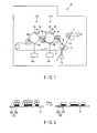
- FIG. 1 is a diagram representing a schematic structure of an image forming apparatus according to an embodiment.
- an image forming apparatus 20 includes an intermediate transfer belt 7, a second image forming unit 17B and a first image forming unit 17A provided in order on the intermediate transfer belt 7, and a fixing unit 21 provided on the downstream side.
- the first image forming unit 17A includes a photoconductive drum 1a, a cleaning device 16a, a charger 2a, an exposure device 3a, a first developing section 4a, and a primary transfer roller 8a.
- the cleaning device 16a, the charger 2a, the exposure device 3a, and the first developing section 4a are provided in order on the photoconductive drum 1a.
- the primary transfer roller 8a is provided downstream of the first developing section 4a via the intermediate transfer belt 7.
- the first developing section 4a stores a color erasable developing agent that includes capsule colorant microparticles with a core in which a color developable compound, a color developing agent, and a color erasing agent are contained.
- the second image forming unit 17B includes a photoconductive drum 1b, a cleaning device 16b, a charger 2b, an exposure device 3b, a second developing section 4b, and a primary transfer roller 8b.
- the cleaning device 16b, the charger 2b, the exposure device 3b, and the second developing section 4b are provided in order on the photoconductive drum 1b.
- the primary transfer roller 8b is provided downstream of the first developing section 4b via the intermediate transfer belt 7.
- the second developing section 4b stores a binder resin-containing transparent developing agent.
- a secondary transfer roller 9 and a backup roller 10 are disposed face to face via the intermediate transfer belt 7 on the downstream side of the second image forming unit 17B.
- the primary transfer roller 8a and the primary transfer roller 8b are connected to a primary transfer power supply 14a and a primary transfer power supply 14b, respectively.
- the secondary transfer roller 9 is connected to a secondary transfer power supply 15.
- the fixing unit 21 includes a heat roller 11 and a pressure roller 12 disposed face to face.
- the apparatus of FIG. 1 can be used to form an image, for example, as follows.
- the charger 2b uniformly charges the photoconductive drum 1b.
- an electrostatic latent image which is formed by exposing the photoconductive drum 1b with the exposure device 3b based on second image information used to form an image capable of covering a first developing agent image formed by the first image forming unit 17A based on first image information.
- the electrostatic latent image is then developed with the binder resin-containing transparent developing agent to form a transparent second developing agent image.
- the second developing agent image is transferred onto the intermediate transfer belt 7 using the primary transfer roller 8b.
- the charger 2a then uniformly charges the photoconductive drum 1a.
- the exposure device 3a exposes the photoconductive drum 1a based on the first image information to form an electrostatic latent image.
- a color erasable first developing agent image is formed by developing the electrostatic latent image with the color erasable developing agent that includes capsule colorant microparticles with a core in which a color developable compound, a color developing agent, and a color erasing agent are contained.
- the first developing agent image is then transferred onto the second developing agent image (primary transfer) using the primary transfer roller 8a, while making sure that the first developing agent image is in register with and covered by the transparent second developing agent image on the intermediate transfer belt 7.
- the primary developing agent image laminated in order of the second developing agent image and the first developing agent image on the intermediate transfer belt 7 is then transferred onto a recording medium 13 (secondary transfer) via the secondary transfer roller 9 and the backup roller 10 to form a secondary developing agent image formed from the first developing agent image and the second developing agent image laminated on the recording medium 13 in this order.
- the fixing unit 21 applies heat and pressure with the heating roller 11 and the pressure roller 12 to fix the developing agent image on the recording medium 13.
- FIG. 2 shows a model diagram representing fixing of the secondary developing agent image.
- a secondary developing agent image 100 formed from a first developing agent image 101 and a second developing agent image 102 laminated on the first developing agent image 101 so as to cover the first developing agent image 101 is fixd on the recording medium.
- the capsule colorant microparticles 101' contained in the resulting image 100' do not assume a non-uniform state, and do not separate from a binder resin 102' during the electrophotographic process.
- the color erasable developing agent can be decolored at a decoloring temperature higher than the fixing temperature of the fixing unit. Accordingly, there is no decoloration upon the fixing alone. Further, the color erasable developing agent has such a hysteresis characteristic that the decolored state is maintained even if the temperature of the color erasable developing agent becomes lower than the decoloring temperature after the decoloration.
- the decoloring temperature of the color erasable developing agent may be set to a temperature at least 5°C higher than the fixing temperature of the fixing unit.
- a less than 5°C difference between the decoloring temperature and the fixing temperature may result in simultaneous decoloration at the time of fixing under the influence of, for example, the temperature ripple in the fixing unit.
- the decoloring temperature may be set to, for example, 79°C to 103°C.
- the capsule colorant microparticles can be layered at the same level on the transfer medium as illustrated in FIG. 1 , the reflecting density can be increased more than that of the pigments that are distant apart from one another, provided that the amounts of the colorant are the same.
- the color erasing agent is encapsulated, the colorant, the color developing agent, and the color developable compound that enable decoloration at a specific temperature can be brought closer to one another, and accordingly the decolor reaction can be made faster and more complete. Further, stable image formation can be realized by the configuration in which the capsule colorant microparticles and the binder resin particles are treated as separate developing agents, and in which the color erasable developing agent image is covered with the resin heated to melt and pressurized in the fixing, because such a configuration allows the development and transfer processes to be optimized according to the charging characteristic of each developing agent.
- the amount of the developed binder resin can be limited to an amount necessary to bind the capsule colorant microparticles to the transfer medium.
- FIG. 3 to FIG. 5 illustrate exemplary schematic structures of image forming apparatuses of other embodiments.
- FIG. 3 to FIG. 5 the cleaning device, the charger, and the exposure device provided for the photoconductive drum are not illustrated for simplicity, and will not be described.
- the image forming apparatus illustrated in FIG. 3 is configured in the same manner as in FIG. 1 , except that the intermediate transfer belt 7 is not provided, and that the first developing agent image and the second developing agent image are directly transferred to the recording medium with the first image forming unit 17A and the second image forming unit 17B disposed in the reversed order from shown in FIG. 1 .
- the developing agent image formed from the first developing agent image and the second developing agent image laminated in this order can be obtained on the recording medium as in FIG. 2 with the first image forming unit 17A and the second image forming unit 17B disposed in the reversed order from that shown FIG. 1 .
- the image forming apparatus illustrated in FIG. 4 is configured in substantially the same manner as in FIG. 1 , except that the second developing section 4b and the first developing section 4a are disposed to face a single photoconductive drum 1, instead of being disposed to face their respective photoconductive drums, namely, the second photoconductive drum 1b and the first photoconductive drum 1a.
- the second developing agent image and the first developing agent image are developed in this order on the photoconductive drum 1, and transferred onto the intermediate transfer belt 7 with a transfer roller 8.
- the developing agent image formed from the first developing agent image and the second developing agent image laminated in this order can be obtained on the recording medium as in FIG. 2 upon transferring the developing agent image transferred onto the intermediate transfer belt 7 to the recording medium 13 using the secondary transfer roller 9 and the backup roller 10.
- the image forming apparatus illustrated in FIG. 5 is configured in the same manner as in FIG. 4 , except that the intermediate transfer belt 7 is not used, and that the first developing agent image and the second developing agent image are directly transferred onto the recording medium with the first image forming unit 17A and the second image forming unit 17B disposed in the reversed order from shown in FIG. 4 .
- the developing agent image formed from the first developing agent image and the second developing agent image laminated in this order can be obtained on the recording medium as in FIG. 2 with the first image forming unit 17A and the second image forming unit 17B disposed in the reversed order from that shown FIG. 4 .
- the first image forming unit 17A and the second image forming unit 17B, or the first developing section 4a and the second developing section 4b on the photoconductive drum 1 may be disposed in the reversed order, though not illustrated.
- the developing agent image on the recording medium is formed from the second developing agent image and the first developing agent image laminated in this order.
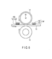
- FIG. 6 is a model diagram representing fixing.
- a heating roller 11 illustrated in FIG. 6 includes a Si rubber elastic layer (thickness 2 mm) and a PFA protective layer (thickness 30 ⁇ m) laminated on a 1 mm-thick SUS (outer diameter 25 mm), and a halogen lamp 22 is installed therein.
- the heating and pressing time is about 67 msec for a recording medium passing at 60 mm/sec, and about 133 msec for a recording medium passing at 120 mm/sec.
- FIG. 6 represents fixing of a developing agent image 100 obtained by laminating the first developing agent image 101 and the second developing agent image 102 in this order on the recording medium as in FIG. 2 .
- the heating roller 11 heats and melts the binder resin particles 102 to be melted under sufficient heat. Because the capsule colorant microparticles 101' in the resulting image 100' are not in direct contact with the heating roller 11, the capsule colorant microparticles 101' do not easily reach the decoloring temperature, and are likely to be sufficiently covered by the binder resin particles 102 melted. As a result, fixing tends to be desirable.
- the heating roller 11 and the pressure roller 12 of FIG. 6 may be switched in position to dispose the heating roller 11 of the fixing unit on the back side of the recording medium, because it makes it easier to heat and melt the binder resin particles 102 and to improve fixing.
- the position of the heating roller in the fixing unit can be freely changed, depending on how the capsule colorant microparticles and the binder resin particles are disposed in the developing agent image transferred onto the recording medium.
- the following describes the color developable compound (leuco dye, etc.), the color developing agent, and the color erasing agent used in the embodiment.
- the leuco dye is an electron-donating compound that can develop color with the color developing agent.
- Examples of the leuco dye include diphenylmethane phthalides, phenylindolyl phthalides, indolyl phthalides, diphenylmethane azaphthalides, phenylindolyl azaphthalides, fluorans, styrylquinolines, and diazarhodamine lactones.
- the color developing agent used in the embodiment is an electron-accepting compound that donates a proton to the leuco dye.
- the color developing agent include phenols, phenol metal salts, carboxylic acid metal salts, aromatic carboxylic acids, aliphatic carboxylic acids of 2 to 5 carbon atoms, benzophenones, sulfonic acids, sulfonates, phosphoric acids, phosphoric acid metal salts, acidic phosphoric acid esters, acidic phosphoric acid ester metal salts, phosphorous acids, phosphorous acid metal salts, monophenols, polyphenols, 1, 2, 3-triazole, and derivatives thereof, either unsubstituted or substituted with substituents such as an alkyl group, an aryl group, an acyl group, an alkoxycarbonyl group, a carboxy group, esters of these, an amide group, and a halogen group.
- Other examples include bis-, tris-phenols, phenol-aldehyde con
- phenol, o-cresol, tert-butylcatechol nonylphenol, n-octylphenol, n-dodecylphenol, n-stearylphenol, p-chlorophenol, p-bromophenol, o-phenylphenol, n-butyl p-hydroxybenzoate, n-octyl p-hydroxybenzoate, benzyl p-hydroxybenzoate, dihydroxybenzoic acid and an ester thereof (for example, 2,3-dihydroxybenzoic acid, and methyl 3,5-dihydroxybenzoate), resorcin, gallic acid, dodecyl gallate, ethyl gallate, butyl gallate, propyl gallate, 2,2-bis(4-hydroxyphenyl)propane, 4,4-dihydroxydiphenylsulfone, 1,1-bis(4-hydroxyphenyl)ethane, 2,2-bis(4-hydroxy-3-methyl
- the color erasing agent used in the embodiment may be a known color erasing agent, provided that it can erase color by inhibiting the chromogenic reaction between the leuco dye and the color developing agent under heat in the three-component system of the color developable compound, the color developing agent, and the color erasing agent.
- the color erasing agent may be used in the form of (1) a dispersion of a color component (developing a color by the binding of the leuco dye and the color developing agent) and a color erasing agent component in a medium that has small or no color-developing and decoloring effects, or (2) a color erasing agent component used as a medium of the component developing a color by the binding of the leuco dye and the color developing agent.
- the color erasing agent used in the form (2) is known from JP-A-60-264285 , JP-A-2005-1369 , and JP-A-2008-280523 , which describe a color-decolor mechanism utilizing the temperature hysteresis of the color erasing agent and thus having superior instantaneous erasability.
- the color of the three-component system mixture can be erased by heating the mixture to a temperature equal to or greater than a specific decoloration temperature Th. The decolored state can be maintained even after the decolored mixture is cooled down to a temperature below Th.
- a reversible color-decolor reaction can take place, whereby the chromogenic reaction between the leuco dye and the color developing agent is restored at or below a specific color restoring temperature Tc to return to the colored state.
- the color erasing agent used in the embodiment satisfies the relation Th > Tr > Tc, where Tr is room temperature.
- color erasing agents that can exhibit such temperature hysteresis include alcohols, esters, ketones, ethers, and acid amides.
- esters are particularly preferred. Specific examples include carboxylic acid esters that contain a substituted aromatic ring; esters of unsubstituted aromatic ring-containing carboxylic acid and aliphatic alcohol; carboxylic acid esters that contain a cyclohexyl group within the molecule; esters of fatty acid and unsubstituted aromatic alcohol or phenol; esters of fatty acid and branched aliphatic alcohol; esters of dicarboxylic acid and aromatic alcohol or branched aliphatic alcohol; dibenzyl cinnamate; heptyl stearate; didecyl adipate; dilauryl adipate; dimyristyl adipate; dicetyl adipate; distearyl adipate; trilaurin; trimyristin; tristearin; dimyristin; and distearin. These may be used as a mixture of two or more.
- the color erasing agent of the form (1) may be one known from, for example, JP-A-2000-19770 .
- Examples include cholesterol, stigmasterol, pregnenolone, methyl androstenediol, estradiol benzoate, epiandrosterone, stenolon, ( ⁇ -sitosterol, pregnenoloneacetate, ( ⁇ -cholestanol, 5,16-pregnadiene-3 ⁇ -ol-20-one, 5 ⁇ -pregnen-3 ⁇ -ol-20-one, 5-pregnen-3 ⁇ , 17-diol-20-one-21-acetate, 5-pregnen-3 ⁇ , 17-diol-20-one-17-acetate, 5-pregnen-3 ⁇ , 21-diol-20-one-21-acetate, 5-pregnen-3 ⁇ , 17-diol diacetate, rockogenin, tigogenin, esmilagenin, hecogenin, diosgenin, cholic acid, cholic acid methyl
- the mixed proportions of the leuco dye, the color developing agent, and the color erasing agent vary with the concentration, the discoloration temperature, and the type of each component.
- the proportion of the color developing agent ranges from 0.1 to 100, preferably 0.1 to 50, more preferably 0.5 to 20, and the proportion of the color erasing agent ranges from 1 to 800, preferably 5 to 200, more preferably 5 to 100 with respect to the leuco dye 1 in terms of a weight ratio.
- a color erasable toner composition was uniformly heated and dissolved to obtain a core solution.
- the color erasable toner composition contained 1 weight part of the color developable compound 3-(2-ethoxy-4-diethylaminophenyl)-3-(1-ethyl-2-methylindol -3-yl)-4-azaphthalide, 5 weight parts of the color-forming agent 2,2-bis(4'-hydroxyphenyl)hexafluoropropane, and 50 weight parts of a diester of pimelic acid and 2-(4-benzyloxyphenyl)ethanol as the color erasing agent.
- An aromatic polyvalent isocyanate prepolymer (25 weight parts; wall material), and ethyl acetate (25 weight parts; co-solvent) were then mixed with 25 weight parts of the color developable compound composition to obtain a core-shell solution.
- the core-shell solution was emulsified and dispersed as micro droplets in the polyvinyl alcohol aqueous solution, and water-soluble aliphatic modified amine was added after stirring the mixture under heat. The mixture was further stirred to obtain a capsule colorant microparticle suspension. The suspension was centrifuged to isolate the capsule colorant microparticles (1).
- the capsule colorant microparticles (1) had a volume average particle diameter of 5 ⁇ m, a complete decoloring temperature of 79°C, and a complete color developing temperature of -10°C. The color of the capsule colorant microparticles (1) reversibly changes between a blue color and colorless with temperature changes.
- Silica Nippon Aerosil Co. , Ltd. ; 3 weight parts
- titanium oxide Nippon Aerosil Co., Ltd.; 1.2 weight parts
- a color erasable toner composition that contained the color developable compound crystal violet lactone (1 weight part), the color developing agent benzyl 4-hydroxybenzoate (5 weight parts), and the color erasing agent 4-benzyloxyphenylethyl laurate (50 weight parts) was uniformly heated and dissolved to obtain a core solution.
- the core-shell solution was emulsified and dispersed as micro droplets in the polyvinyl alcohol aqueous solution, and water-soluble aliphatic modified amine was added after stirring the mixture under heat. The mixture was further stirred to obtain a capsule colorant microparticle suspension. The suspension was then centrifuged to isolate the capsule colorant microparticles (2).
- the capsule colorant microparticles (2) had a volume average particle diameter of 5 ⁇ m, a complete decoloring temperature of 103°C, and a complete color developing temperature of -15°C. The color of the capsule colorant microparticles (2) reversibly changes between a blue color and colorless with temperature changes.
- Silica (NAX50 : Nippon Aerosil Co. , Ltd. ; 3 weight parts), and titanium oxide (NKT90: Nippon Aerosil Co., Ltd.; 1.2 weight parts) were mixed with the capsule colorant microparticles (2) (100 weight parts), and thoroughly stirred to cause the inorganic microparticles to uniformly adhere to the surfaces of the capsule colorant microparticles (2).
- These particles (6 weight parts) and carrier particles (94 weight parts) that had a volume average particle diameter of 40 ⁇ m and obtained by the acryl resin coating of a ferrite surface were mixed to obtain developing agent A (2).
- the developing agent A (2) was charged to an average charge of -25 ⁇ C/g.
- Terephthalic acid 39 parts by mass
- a bisphenol A ethylene oxide compound 61 parts by mass
- dibutyltin 0.2 parts by mass
- the polyester resin had a glass transition temperature Tg of 60°C, a softening point Tm of 110°C, and a weight average molecular weight of 12,000.
- the polyester resin (95 weight parts) was then mixed and kneaded with a release agent (rice wax; 5 weight parts), pulverized, and classified to obtain resin particles (1) that had a volume average particle diameter of 9.8 ⁇ m.
- silica (NAX50; 1.7 weight parts) and titanium oxide (NKT90; 0.6 weight parts) were then mixed with the resin particles (1) (100 weight parts), and thoroughly stirred to cause the inorganic microparticles to uniformly adhere to the surfaces of the resin particles.
- These particles (8 weight parts) were mixed with carrier particles (92 weight parts) that had a volume average particle diameter of 40 ⁇ m and obtained by the acryl resin coating of a ferrite surface.
- developing agent B (1) was obtained.
- the developing agent B (1) was charged to an average charge of -31 ⁇ C/g.
- the middle point of the stroke position between the softening point and the end of the flow was measured as the temperature Tm (softening point).
- the polyester resin was pulverized, and sodium dodecylbenzenesulfonate (0.4 parts) and tritylamine (1 part) were added to prepare a suspension.
- the suspension was atomized by mechanical shear using a high-pressure homogenizer, and a dispersion of binder resin-containing particles was prepared as a core solution.
- Styrene (90 parts by mass), n-butyl acrylate (10 parts by mass), sodium p-styrenesulfonate (100 ppm), the chain transfer agent tert-dodecylmercaptan (1.5 parts by mass), the emulsifier Latemul PS (Kao Corporation; 0.5 parts by mass) were added, and emulsion polymerization was performed at 60°C upon adding the polymerization initiator ammonium persulfate (0.8 parts by mass) to obtain a styrene-acryl resin emulsion as a shell solution.
- the styrene-acryl resin had a glass transition temperature of 80°C, and a weight average molecular weight of 25,000.
- a dispersion of the binder resin-containing particles (95 parts by mass) , and a dispersion of the release agent (rice wax; 5 parts by mass) were agglomerated at 50°C with aluminum sulfate A12 ( SO 4 ) 3 (3.0 mass%), and the styrene-acryl resin emulsion (20 parts by mass) was added to encapsulate the resin particles.
- the temperature was raised to 75°C at a rate of temperature increase of 5°C/30 min, followed by washing and drying.
- resin particles (2) with a volume average particle diameter of 10.3 ⁇ m were obtained.
- silica (NAX50; 1.6 weight parts) and titanium oxide (NKT90; 0.5 weight parts) were then added to the resin particles (2) (100 weight parts), and the mixture was thoroughly stirred to cause the inorganic microparticles to uniformly adhere to the resin particle surface.
- These particles (8 weight parts) were then mixed with carrier particles (92 weight parts) that had a volume average particle diameter of 40 ⁇ m and obtained by the acryl resin coating of a ferrite surface.
- developing agent B (2) was obtained.
- the developing agent B (2) was charged to an average charge of -32 ⁇ C/g.
- the developing agent B (1) and the developing agent A (1) were stored in the second developing section 4b and the first developing section 4a, respectively, of the image forming apparatus illustrated in FIG. 1 .
- the capsule colorant microparticles (1) and the resin particles (1) were then transferred onto a recording medium in the form of an image.
- the fixing unit temperature set to 73°C
- the recording medium was passed through the fixing unit at about 60 mm/sec (15 ppm) .
- the heat and pressure applied in the nip of the fixing unit melted the fusing binder resin without raising the temperature of the coloring agent to the decoloring temperature, and the binder resin, having coated the colored particles, was cooled outside of the fixing unit to obtain a fixed color image on the recording medium.
- Heating the color image to 79°C or higher using an erasing apparatus decolored the coloring agent, and enabled the recording medium to be reused as a blank sheet of paper.
- the developing agent B (2) and the developing agent A (2) were stored in the developing section 4b and the developing section 4a, respectively, and the capsule colorant microparticles (2) and the resin particles (2) were transferred onto a recording medium in the form of an image.
- the fixing unit r temperature set to 85°C
- the recording medium was passed through the fixing unit at about 120 mm/sec (28 ppm).
- the applied heat and pressure in the nip of the fixing unit melted the fixing binder resin without raising the temperature of the coloring agent to the decoloring temperature, and the binder resin, having coated the colored particles, was cooled outside of the fixing unit to obtain a fixed color image on the recording medium.
- Heating the color image to 103°C or higher using an erasing apparatus decolored the coloring agent, and enabled the recording medium to be reused as a blank sheet of paper.
Landscapes
- Physics & Mathematics (AREA)
- General Physics & Mathematics (AREA)
- Engineering & Computer Science (AREA)
- Computer Vision & Pattern Recognition (AREA)
- Developing Agents For Electrophotography (AREA)
- Color Printing (AREA)
Applications Claiming Priority (1)
| Application Number | Priority Date | Filing Date | Title |
|---|---|---|---|
| US38993510P | 2010-10-05 | 2010-10-05 |
Publications (2)
| Publication Number | Publication Date |
|---|---|
| EP2439599A2 true EP2439599A2 (fr) | 2012-04-11 |
| EP2439599A3 EP2439599A3 (fr) | 2015-05-27 |
Family
ID=44799694
Family Applications (1)
| Application Number | Title | Priority Date | Filing Date |
|---|---|---|---|
| EP11183755.5A Withdrawn EP2439599A3 (fr) | 2010-10-05 | 2011-10-04 | Procédé et appareil de formation d'images |
Country Status (4)
| Country | Link |
|---|---|
| US (1) | US20120082484A1 (fr) |
| EP (1) | EP2439599A3 (fr) |
| KR (1) | KR20120035865A (fr) |
| CN (1) | CN102445881B (fr) |
Families Citing this family (7)
| Publication number | Priority date | Publication date | Assignee | Title |
|---|---|---|---|---|
| JP5746234B2 (ja) * | 2013-01-30 | 2015-07-08 | 株式会社東芝 | 画像形成装置、消去装置 |
| CN103092038B (zh) * | 2013-02-20 | 2016-05-04 | 吴涛 | 一种打印、复印方法和设备 |
| US9452628B2 (en) | 2015-02-03 | 2016-09-27 | Kabushiki Kaisha Toshiba | Image decoloring apparatus |
| US9342029B1 (en) * | 2015-09-29 | 2016-05-17 | Kabushiki Kaisha Toshiba | Image forming apparatus that forms an image with a decolorable material and a non-decolorable material and method for forming the image |
| US9996025B1 (en) * | 2017-03-02 | 2018-06-12 | Kabushiki Kaisha Toshiba | Cartridge, image forming apparatus and image forming method |
| JP2019128472A (ja) * | 2018-01-25 | 2019-08-01 | 株式会社東芝 | 画像形成装置 |
| US20200117109A1 (en) * | 2018-10-12 | 2020-04-16 | Toshiba Tec Kabushiki Kaisha | Decolorizable toner, toner cartridge, image forming apparatus, decolorizing system, decolorizing method, and decolorizing device |
Citations (4)
| Publication number | Priority date | Publication date | Assignee | Title |
|---|---|---|---|---|
| JPS60264285A (ja) | 1984-06-13 | 1985-12-27 | Pilot Ink Co Ltd | 可逆性感熱記録組成物 |
| JP2000019770A (ja) | 1998-06-30 | 2000-01-21 | Toshiba Corp | 消去可能な画像形成材料およびその製造方法 |
| JP2005001369A (ja) | 2003-05-16 | 2005-01-06 | Pilot Ink Co Ltd | 感温変色性色彩記憶性組成物及びそれを内包した感温変色性色彩記憶性マイクロカプセル顔料 |
| JP2008280523A (ja) | 2007-04-12 | 2008-11-20 | Pilot Ink Co Ltd | 感温変色性色彩記憶性組成物及びそれを内包した感温変色性色彩記憶性マイクロカプセル顔料 |
Family Cites Families (7)
| Publication number | Priority date | Publication date | Assignee | Title |
|---|---|---|---|---|
| JP3137465B2 (ja) * | 1992-07-31 | 2001-02-19 | 株式会社リコー | 画像形成装置 |
| US20060269328A1 (en) * | 2005-05-27 | 2006-11-30 | Kabushiki Kaisha Toshiba | Image forming apparatus additionally using erasable toner |
| JP2008009311A (ja) * | 2006-06-30 | 2008-01-17 | Toshiba Corp | 現像装置、画像形成装置、現像器保持方法 |
| KR101330635B1 (ko) * | 2006-12-26 | 2013-11-25 | 삼성전자주식회사 | 투명토너를 채용한 전자사진방식 화상형성장치 |
| KR20080061749A (ko) * | 2006-12-28 | 2008-07-03 | 삼성전자주식회사 | 투명토너를 채용한 전자사진방식 화상형성장치의 인쇄방법 |
| JP4666077B2 (ja) * | 2009-01-14 | 2011-04-06 | 富士ゼロックス株式会社 | 静電荷像現像用現像剤、静電荷像現像用現像剤カートリッジ、プロセスカートリッジ及び画像形成装置 |
| CN101807018B (zh) * | 2009-02-16 | 2013-10-16 | 东芝泰格有限公司 | 显影剂及其制造方法 |
-
2011
- 2011-09-30 CN CN201110302092.5A patent/CN102445881B/zh not_active Expired - Fee Related
- 2011-09-30 KR KR1020110099839A patent/KR20120035865A/ko not_active Ceased
- 2011-10-03 US US13/251,474 patent/US20120082484A1/en not_active Abandoned
- 2011-10-04 EP EP11183755.5A patent/EP2439599A3/fr not_active Withdrawn
Patent Citations (4)
| Publication number | Priority date | Publication date | Assignee | Title |
|---|---|---|---|---|
| JPS60264285A (ja) | 1984-06-13 | 1985-12-27 | Pilot Ink Co Ltd | 可逆性感熱記録組成物 |
| JP2000019770A (ja) | 1998-06-30 | 2000-01-21 | Toshiba Corp | 消去可能な画像形成材料およびその製造方法 |
| JP2005001369A (ja) | 2003-05-16 | 2005-01-06 | Pilot Ink Co Ltd | 感温変色性色彩記憶性組成物及びそれを内包した感温変色性色彩記憶性マイクロカプセル顔料 |
| JP2008280523A (ja) | 2007-04-12 | 2008-11-20 | Pilot Ink Co Ltd | 感温変色性色彩記憶性組成物及びそれを内包した感温変色性色彩記憶性マイクロカプセル顔料 |
Also Published As
| Publication number | Publication date |
|---|---|
| CN102445881B (zh) | 2014-07-02 |
| US20120082484A1 (en) | 2012-04-05 |
| KR20120035865A (ko) | 2012-04-16 |
| EP2439599A3 (fr) | 2015-05-27 |
| CN102445881A (zh) | 2012-05-09 |
Similar Documents
| Publication | Publication Date | Title |
|---|---|---|
| EP2439599A2 (fr) | Procédé et appareil de formation d'images | |
| JP4442676B2 (ja) | 光定着用カラートナー及びその製造方法、並びに、静電荷像現像剤、プロセスカートリッジ及び画像形成装置 | |
| US8426095B2 (en) | Toner | |
| EP2383618A2 (fr) | Appareil de formation d'images | |
| US9671727B2 (en) | Method for erasing image | |
| US8647799B2 (en) | Erasable toner and method for producing the same | |
| EP2381314A1 (fr) | Toner électrophotographique | |
| CN102692837B (zh) | 图像形成方法 | |
| US8885225B2 (en) | Image forming apparatus, image forming method, and image forming material | |
| US9221290B2 (en) | Apparatus and method for forming an image with a plurality of decolorizable materials and for decolorizing the image | |
| US9757969B2 (en) | Apparatus and method for forming an image with a non-decolorizable material and a decolorizable material | |
| US8475993B2 (en) | Toner and method for producing the same | |
| US20120141932A1 (en) | Developer and method for producing the same | |
| US20180329330A1 (en) | Electrophotographic toner set, image forming apparatus, and image forming method | |
| US20130137031A1 (en) | Electrophotographic toner and method for producing the same | |
| US20110262852A1 (en) | Decolorizable electrophotographic toner | |
| JP2012078794A (ja) | 電子写真用トナー、およびその製造方法 | |
| JP2008281642A (ja) | 画像形成装置 |
Legal Events
| Date | Code | Title | Description |
|---|---|---|---|
| 17P | Request for examination filed |
Effective date: 20111004 |
|
| AK | Designated contracting states |
Kind code of ref document: A2 Designated state(s): AL AT BE BG CH CY CZ DE DK EE ES FI FR GB GR HR HU IE IS IT LI LT LU LV MC MK MT NL NO PL PT RO RS SE SI SK SM TR |
|
| AX | Request for extension of the european patent |
Extension state: BA ME |
|
| PUAI | Public reference made under article 153(3) epc to a published international application that has entered the european phase |
Free format text: ORIGINAL CODE: 0009012 |
|
| PUAL | Search report despatched |
Free format text: ORIGINAL CODE: 0009013 |
|
| AK | Designated contracting states |
Kind code of ref document: A3 Designated state(s): AL AT BE BG CH CY CZ DE DK EE ES FI FR GB GR HR HU IE IS IT LI LT LU LV MC MK MT NL NO PL PT RO RS SE SI SK SM TR |
|
| AX | Request for extension of the european patent |
Extension state: BA ME |
|
| RIC1 | Information provided on ipc code assigned before grant |
Ipc: G03G 15/01 20060101AFI20150420BHEP Ipc: G03G 15/08 20060101ALI20150420BHEP |
|
| STAA | Information on the status of an ep patent application or granted ep patent |
Free format text: STATUS: THE APPLICATION HAS BEEN WITHDRAWN |
|
| 18W | Application withdrawn |
Effective date: 20150709 |