EP2439829A2 - Agencement destiné à la mise hors service sécurisée d'installations photovoltaïques - Google Patents
Agencement destiné à la mise hors service sécurisée d'installations photovoltaïques Download PDFInfo
- Publication number
- EP2439829A2 EP2439829A2 EP11179236A EP11179236A EP2439829A2 EP 2439829 A2 EP2439829 A2 EP 2439829A2 EP 11179236 A EP11179236 A EP 11179236A EP 11179236 A EP11179236 A EP 11179236A EP 2439829 A2 EP2439829 A2 EP 2439829A2
- Authority
- EP
- European Patent Office
- Prior art keywords
- current
- switching device
- voltage
- semiconductor switch
- arrangement according
- Prior art date
- Legal status (The legal status is an assumption and is not a legal conclusion. Google has not performed a legal analysis and makes no representation as to the accuracy of the status listed.)
- Withdrawn
Links
- 230000000712 assembly Effects 0.000 title 1
- 238000000429 assembly Methods 0.000 title 1
- 230000009849 deactivation Effects 0.000 title 1
- 239000004065 semiconductor Substances 0.000 claims abstract description 19
- 239000003990 capacitor Substances 0.000 claims abstract description 18
- 238000002955 isolation Methods 0.000 claims description 2
- 230000001681 protective effect Effects 0.000 description 4
- 238000013461 design Methods 0.000 description 3
- 238000012423 maintenance Methods 0.000 description 2
- 230000009993 protective function Effects 0.000 description 2
- 238000009420 retrofitting Methods 0.000 description 2
- 230000003213 activating effect Effects 0.000 description 1
- 230000005540 biological transmission Effects 0.000 description 1
- 230000000903 blocking effect Effects 0.000 description 1
- 230000001419 dependent effect Effects 0.000 description 1
- 238000011161 development Methods 0.000 description 1
- 230000018109 developmental process Effects 0.000 description 1
- 238000010586 diagram Methods 0.000 description 1
- 238000000034 method Methods 0.000 description 1
- 238000012806 monitoring device Methods 0.000 description 1
- 238000012544 monitoring process Methods 0.000 description 1
- 238000010248 power generation Methods 0.000 description 1
- 238000000926 separation method Methods 0.000 description 1
- 230000011664 signaling Effects 0.000 description 1
- 230000001960 triggered effect Effects 0.000 description 1
Images


Classifications
-
- H—ELECTRICITY
- H10—SEMICONDUCTOR DEVICES; ELECTRIC SOLID-STATE DEVICES NOT OTHERWISE PROVIDED FOR
- H10F—INORGANIC SEMICONDUCTOR DEVICES SENSITIVE TO INFRARED RADIATION, LIGHT, ELECTROMAGNETIC RADIATION OF SHORTER WAVELENGTH OR CORPUSCULAR RADIATION
- H10F77/00—Constructional details of devices covered by this subclass
- H10F77/95—Circuit arrangements
- H10F77/953—Circuit arrangements for devices having potential barriers
- H10F77/955—Circuit arrangements for devices having potential barriers for photovoltaic devices
-
- H—ELECTRICITY
- H02—GENERATION; CONVERSION OR DISTRIBUTION OF ELECTRIC POWER
- H02H—EMERGENCY PROTECTIVE CIRCUIT ARRANGEMENTS
- H02H7/00—Emergency protective circuit arrangements specially adapted for specific types of electric machines or apparatus or for sectionalised protection of cable or line systems, and effecting automatic switching in the event of an undesired change from normal working conditions
- H02H7/20—Emergency protective circuit arrangements specially adapted for specific types of electric machines or apparatus or for sectionalised protection of cable or line systems, and effecting automatic switching in the event of an undesired change from normal working conditions for electronic equipment
- H02H7/205—Emergency protective circuit arrangements specially adapted for specific types of electric machines or apparatus or for sectionalised protection of cable or line systems, and effecting automatic switching in the event of an undesired change from normal working conditions for electronic equipment for controlled semi-conductors which are not included in a specific circuit arrangement
-
- Y—GENERAL TAGGING OF NEW TECHNOLOGICAL DEVELOPMENTS; GENERAL TAGGING OF CROSS-SECTIONAL TECHNOLOGIES SPANNING OVER SEVERAL SECTIONS OF THE IPC; TECHNICAL SUBJECTS COVERED BY FORMER USPC CROSS-REFERENCE ART COLLECTIONS [XRACs] AND DIGESTS
- Y02—TECHNOLOGIES OR APPLICATIONS FOR MITIGATION OR ADAPTATION AGAINST CLIMATE CHANGE
- Y02E—REDUCTION OF GREENHOUSE GAS [GHG] EMISSIONS, RELATED TO ENERGY GENERATION, TRANSMISSION OR DISTRIBUTION
- Y02E10/00—Energy generation through renewable energy sources
- Y02E10/50—Photovoltaic [PV] energy
Definitions
- the invention relates to an arrangement for safe decommissioning of photovoltaic systems, which have a plurality of interconnected at least one string modules, wherein the at least one string can be converted by a controllable switching device in a short circuit state, according to claim 1.
- thermo switch is after EP 1 720 241 A2 each switching element understood, which initiates a switching operation upon reaching a predetermined or predetermined temperature or other fire-indicating parameter, which leads directly or indirectly to close or open an electrical connection.
- the thermal switch can be located in, but also outside of the module housing to optimize the response. For the desired electrical bridging in the event of thermal hazard, a strand of a photovoltaic system is provided with the aforementioned thermal switch and bridged.
- EP 1 720 241 A2 A disadvantage of the arrangement according to EP 1 720 241 A2 is the need to detect a clear fire, especially by correspondingly high temperatures. A manual operation is also not possible, as in an intended fire extinguishing is not recognizable whether the photovoltaic system in question is actually in a voltage-free state.
- the short-circuit device is operated via a sensor system, which preferably also triggers the short-circuit case depending on the temperature. So are also at This solution of the prior art given the disadvantages described above.
- load disconnectors are able to separate the DC voltage of the photovoltaic cells from the downstream inverter.
- the disadvantage with the use of load disconnectors is that the high DC voltage with up to 1000 V stops on the system and continues to pose a hazard.
- a switching device for safe interruption of operation of photovoltaic systems where the task is solved, regardless of whether there is already a line fault or not to allow in dangerous situations, an immediate shutdown of the photovoltaic system.
- the local switching device has a triggerable by a control signal protection device, which transfers the photovoltaic generator field in a safe operating point, which allows no further energy delivery into the building.
- the generator field remains in the safe operating point until it is reactivated by intervention on the protective device.
- the protective device is connected via a control line to a tripping device arranged away from the protective device, via which the protective device can be activated.
- the triggering device is in one embodiment, a manually triggerable switch in the form of an emergency or key switch.
- the DE 40 41 672 A1 shows a monitoring device for a DC circuit and a so equipped photovoltaic power generation plant.
- a bistable relay with a switch as a short circuiter is available.
- This switch is another, hand switch connected in parallel to form a second short circuit, such that after closing the first switch, the bistable relay can be opened again. It is assumed in this regard explicitly by a manual operation of the relay. To the plant after DE 40 41 672 A1 To bring back to the normal operating state, the manual switch must first be opened, which then breaks the second Kur gleichstrom Vietnamese and the generated generator current is in turn supplied to the inverter. It is therefore necessary to open the handset under load and dimension accordingly.
- the controllable switching device is designed as a current-carrying semiconductor switch, in particular as a thyristor, to whose control input a turn-off signal can be applied.
- the current-carrying semiconductor switch is another switching device, in particular designed as a transistor, connected in parallel so that it can be reset by a short-term assumption of the load current of the current-carrying semiconductor switch.
- a capacitor is powered from the photovoltaic system via a voltage divider, the capacitor being connectable to the control input of the particular thyristor to detect the short circuit condition, e.g. in the case of a danger to achieve or to achieve.
- a remote switching device which has a mains-independent power supply and an emergency stop button. Furthermore, the remote switching device is electrically isolated connected to the control input of the current-carrying semiconductor switch. About such a switching device and several photovoltaic systems with appropriate controllable switching device in case of danger can be put out of service.
- an optocoupler is provided, which is the output side connected to the control input of the current-carrying semiconductor switch in combination.
- the off-grid power supply for the remote switching device may include a solar cell and a related in this connection with the solar cell storage capacitor.
- the remote switching device has a voltmeter which is connected to the string poles via a voltage divider. After pressing the emergency stop button of the remote switching device is then clearly visible, whether in fact the photovoltaic system was disabled.
- the elements of the remote switching device are preferably integrated in a common housing.
- load disconnectors can be made between the respective photovoltaic systems and the respectively associated inverters.
- the further switching device is designed as a transistor, at the base of which a voltage for resetting the current-carrying semiconductor switch is applied, this voltage being made available from a capacitor which is charged via a voltage-limiting diode as well as a voltage divider and a freewheeling diode via the string poles.
- the solution according to the invention uses the short-circuiting technique known per se, but not on the individual module, but on the string of the photovoltaic system. As a result, the entire system can be switched off and safely deleted in case of fire.
- a load breaker additionally ensures the necessary disconnection from the inverter, which results in advantages in the maintenance of the system.
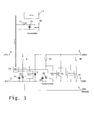
- Fig. 1 can be removed, is between the DC poles of a string, which is an interconnection of multiple PV modules, a current-carrying semiconductor switch 1 is located.
- the current-carrying semiconductor switch 1 is connected to a control electronics 3 in connection, which in turn is activated by an emergency stop button assembly with voltage indicator 4. Between the in the Fig. 1 not shown in detail PV modules with inverters also not shown is still a load disconnector 2 connected.
- the emergency stop button 4 When the emergency stop button 4 is actuated, the protective function is triggered by resorting to the control electronics 3 and the semiconductor switch 1 is transferred to the short-circuit state. As a result, the voltage at the relevant photovoltaic system is brought to a harmless value below 60 V DC.
- the protective function can be reset manually via the load disconnector 2.
- the load disconnector 2 also allow a separation of the system from the inverter during maintenance.
- the control electronics 3 and the emergency stop button 4 with voltage display and the other components of the arrangement according to the invention are intended with reference to the Fig. 2 be explained in more detail.
- a thyristor 6 as a current-carrying semiconductor switch.
- the control input of the thyristor 6 is connected to an emergency stop switch 7 in electrical connection.
- the emergency stop button 7 is closed. In this case, energy stored in the capacitor 8 is applied to the gate, i. the control input of the thyristor 6 out.
- the capacitor 8 is powered by a voltage divider 9 and a Zener diode 10 with energy, the voltage divider 9 forms a series circuit with the Zener diode 10 and in this regard is disposed between the stranded poles 5.
- Another way of activating the arrangement for safe shutdown of photovoltaic systems is to use a remote switching device.
- the remote switching device includes an external emergency stop button 11, a network-independent power supply 12 and a memory device, in particular a storage capacitor 13th
- the off-grid power supply 12 may be e.g. be designed as a solar cell.
- the emergency stop button 11 is actuated, galvanically, separated via an optocoupler 14, energy is applied to the gate of the thyristor 6, so that it passes into the conductive state.
- the optocoupler 14 is the output side with a switching transistor 16 in connection.
- the voltmeter 17 When the thyristor is in the conducting state, the voltmeter 17 does not indicate any voltage. This makes it possible to check whether the decommissioning was successful.
- the voltmeter 17 is connected to the string poles 15 via a voltage divider arrangement 18.
- a zener diode 19 protects the voltmeter from voltage surges.
- the thyristor 6 is connected in parallel with another switching device 20, in particular a transistor.
- the transistor 20 is able to realize a short-term assumption of the load current of the thyristor, so that the latter can be reset.
- the base of the transistor 20 is connected to a reset button 21 in connection.
- the capacitor 22 is discharged and the transistor 20 is turned on.
- the transistor 20 takes over the load current for a short time when the base of the transistor 20 is driven via the reset switch 21.
- the thyristor 6 then goes back into the blocking state and the voltmeter 17 indicates the now again applied full strand voltage.
- the emergency stop circuit is made via the emergency stop button 11 and this also the reset triggering, wherein the relevant switching commands are transmitted via a bus line.
- a bus line To the bus line is a preferred LCD display 17 instead of a conventional analog voltmeter according to the embodiment according to Fig. 2 connected.
- a voltage measuring module is provided for providing corresponding digital data and their transmission via the bus line in the short-circuit box.
- a signal WR disable at connection point 4 the photovoltaic system can be de-energized when the inverter is selected, so that no more energy is entered into the inverter.
- a fire alarm system or other signaling devices can be connected, which switch the system de-energized.
- the controllable switching device is designed as a thyristor 6, at whose control input a turn-off signal can be applied. Furthermore, a capacitor 8 is present, which is supplied from the photovoltaic system with energy, wherein the capacitor 8 is connected to the control input of the thyristor 6.
- the short-circuit state is initiated.
- a transistor 20 is connected in parallel in such a way that the thyristor is reset again by briefly taking over the load current.
- a reset voltage for resetting can be applied to the base of the transistor 20, this voltage being provided by a further capacitor 22, which has a voltage-limiting diode 25 is charged by connecting to the string poles.
- a freewheeling diode 24 analogous to the embodiment according to Fig. 2 be provided.
- the remote switch may have an integrated transmitter unit, which preferably operates in the so-called ISM band.
- the power supply of this transmitter device together with the remote switch is via a separate solar cell 12 analogous to the embodiment according to Fig. 2 or 3 realized.
- a tuned frequency side tuned receiver is provided, which receives a coded data telegram in the event of triggering to hereafter the thyristor 6 to ignite.
Landscapes
- Inverter Devices (AREA)
- Power Conversion In General (AREA)
Applications Claiming Priority (2)
| Application Number | Priority Date | Filing Date | Title |
|---|---|---|---|
| DE102010047935 | 2010-10-08 | ||
| DE102010049293A DE102010049293B3 (de) | 2010-09-21 | 2010-10-22 | Anordnung zum sicheren Außerbetriebsetzen von Photovoltaikanlagen |
Publications (2)
| Publication Number | Publication Date |
|---|---|
| EP2439829A2 true EP2439829A2 (fr) | 2012-04-11 |
| EP2439829A3 EP2439829A3 (fr) | 2012-12-05 |
Family
ID=44763855
Family Applications (1)
| Application Number | Title | Priority Date | Filing Date |
|---|---|---|---|
| EP11179236A Withdrawn EP2439829A3 (fr) | 2010-10-08 | 2011-08-30 | Agencement destiné à la mise hors service sécurisée d'installations photovoltaïques |
Country Status (1)
| Country | Link |
|---|---|
| EP (1) | EP2439829A3 (fr) |
Cited By (2)
| Publication number | Priority date | Publication date | Assignee | Title |
|---|---|---|---|---|
| CN108666978A (zh) * | 2018-06-29 | 2018-10-16 | 江苏集能易新能源技术有限公司 | 一种光伏关断器分压电路 |
| CN113726135A (zh) * | 2021-09-24 | 2021-11-30 | 桂林电子科技大学 | 一种mos管分流关断的可控硅开关电路 |
Citations (4)
| Publication number | Priority date | Publication date | Assignee | Title |
|---|---|---|---|---|
| DE4041672A1 (de) | 1990-12-22 | 1992-06-25 | Zsw | Ueberwachungseinrichtung fuer einen gleichstromkreis sowie damit ausgeruestete photovoltaische energiegewinnungsanalge |
| US20020014262A1 (en) | 2000-07-10 | 2002-02-07 | Masaaki Matsushita | Photovoltaic power generation systems and methods of controlling photovoltaic power generation systems |
| EP1720241A2 (fr) | 2005-04-18 | 2006-11-08 | Beck Energy GmbH | Generateur photovoltaique avec interrupteur thermique |
| DE102005018173B4 (de) | 2005-04-19 | 2009-05-14 | Swiontek, Karl, Dipl.-Ing. | Schalteinrichtung zur sicheren Betriebsunterbrechung von Photovoltaikanlagen |
Family Cites Families (2)
| Publication number | Priority date | Publication date | Assignee | Title |
|---|---|---|---|---|
| DE102008052037B3 (de) * | 2008-10-16 | 2010-04-08 | Moeller Gmbh | Solarmodul |
| WO2010078303A2 (fr) * | 2008-12-29 | 2010-07-08 | Atonometrics, Inc. | Système d'arrêt de sécurité électrique et dispositifs pour modules photovoltaïques |
-
2011
- 2011-08-30 EP EP11179236A patent/EP2439829A3/fr not_active Withdrawn
Patent Citations (4)
| Publication number | Priority date | Publication date | Assignee | Title |
|---|---|---|---|---|
| DE4041672A1 (de) | 1990-12-22 | 1992-06-25 | Zsw | Ueberwachungseinrichtung fuer einen gleichstromkreis sowie damit ausgeruestete photovoltaische energiegewinnungsanalge |
| US20020014262A1 (en) | 2000-07-10 | 2002-02-07 | Masaaki Matsushita | Photovoltaic power generation systems and methods of controlling photovoltaic power generation systems |
| EP1720241A2 (fr) | 2005-04-18 | 2006-11-08 | Beck Energy GmbH | Generateur photovoltaique avec interrupteur thermique |
| DE102005018173B4 (de) | 2005-04-19 | 2009-05-14 | Swiontek, Karl, Dipl.-Ing. | Schalteinrichtung zur sicheren Betriebsunterbrechung von Photovoltaikanlagen |
Cited By (3)
| Publication number | Priority date | Publication date | Assignee | Title |
|---|---|---|---|---|
| CN108666978A (zh) * | 2018-06-29 | 2018-10-16 | 江苏集能易新能源技术有限公司 | 一种光伏关断器分压电路 |
| CN108666978B (zh) * | 2018-06-29 | 2024-02-02 | 江苏集能易新能源技术有限公司 | 一种光伏关断器分压电路 |
| CN113726135A (zh) * | 2021-09-24 | 2021-11-30 | 桂林电子科技大学 | 一种mos管分流关断的可控硅开关电路 |
Also Published As
| Publication number | Publication date |
|---|---|
| EP2439829A3 (fr) | 2012-12-05 |
Similar Documents
| Publication | Publication Date | Title |
|---|---|---|
| EP2745327B1 (fr) | Boîte de connexions pour un panneau solaire, pourvue d'un circuit de protection | |
| EP2726889B1 (fr) | Module photovoltaïque | |
| EP2256822A2 (fr) | Installation de commutation de sécurité pour installations solaires | |
| WO2011138314A1 (fr) | Procédé pour limiter la tension de générateur d'une installation photovoltaïque en cas de danger et installation photovoltaïque correspondante | |
| DE102015102468B3 (de) | Netzersatzanlage und Erdungseinrichtung für eine Netzersatzanlage | |
| DE102011083582A1 (de) | Stromverteiler für Kraftfahrzeug-Bordnetze | |
| EP2960945A2 (fr) | Boîtier de raccordement de générateur relié à un onduleur central pour une connection sans arc électrique de modules photovoltaïques | |
| EP2815434B1 (fr) | Mise hors circuit de modules solaires | |
| EP3565074A1 (fr) | Circuit de couplage à fonction de commutation permettant de coupler un appareil de surveillance d'isolation à un système d'alimentation électrique non mis à la masse | |
| DE102010049293B3 (de) | Anordnung zum sicheren Außerbetriebsetzen von Photovoltaikanlagen | |
| WO2015059195A1 (fr) | Système d'onduleur et système pv | |
| DE102010037760B4 (de) | Vorrichtung und Verfahren zur Spannungsfreischaltung elektrischer, in einem Gebäude oder Gebäudekomplex verlaufender Leitungen einer Photovoltaikanlage, Verwendung der Vorrichtung sowie System mit der Vorrichtung und einer Photovoltaikanlage | |
| DE102011018972B4 (de) | Solarmodulschutzvorrichtung | |
| EP2439829A2 (fr) | Agencement destiné à la mise hors service sécurisée d'installations photovoltaïques | |
| AT519847B1 (de) | Elektrische Schalteinrichtung | |
| EP3148028A1 (fr) | Dispositif de protection pour un dispositif d'alimentation en energie et dispositif d'alimentation en energie comprenant un tel dispositif de protection | |
| EP2899738B1 (fr) | Commande externe d'un déclencheur électromagnétique | |
| DE102014201503A1 (de) | Elektrische Schutzanordnung für eine Elektroinstallation sowie dazugehöriges Verfahren | |
| EP2608343B1 (fr) | Alimentation électrique | |
| EP2463914A1 (fr) | Dispositif de sécurité pour installations photovoltaïques | |
| DE102017124567B4 (de) | Batteriesystem, lokales Stromnetz und Trennschalter | |
| DE102010004395A1 (de) | Schaltungsanordnung zum Schutz von Photovoltaikmodulen | |
| DE102013221444B4 (de) | Wechselrichter-System und Energieversorgungsvorrichtung | |
| DE19818022A1 (de) | Versagerschutz für ein Schutzschaltgerät | |
| BE1024324B1 (de) | Photovoltaik-Anlage, Gleichstrom-Hybrid-Schalteinrichtung, Verwendung und Verfahren zum An-und Abschalten eines Photovoltaik-Strangs |
Legal Events
| Date | Code | Title | Description |
|---|---|---|---|
| AK | Designated contracting states |
Kind code of ref document: A2 Designated state(s): AL AT BE BG CH CY CZ DE DK EE ES FI FR GB GR HR HU IE IS IT LI LT LU LV MC MK MT NL NO PL PT RO RS SE SI SK SM TR |
|
| AX | Request for extension of the european patent |
Extension state: BA ME |
|
| PUAI | Public reference made under article 153(3) epc to a published international application that has entered the european phase |
Free format text: ORIGINAL CODE: 0009012 |
|
| PUAL | Search report despatched |
Free format text: ORIGINAL CODE: 0009013 |
|
| AK | Designated contracting states |
Kind code of ref document: A3 Designated state(s): AL AT BE BG CH CY CZ DE DK EE ES FI FR GB GR HR HU IE IS IT LI LT LU LV MC MK MT NL NO PL PT RO RS SE SI SK SM TR |
|
| AX | Request for extension of the european patent |
Extension state: BA ME |
|
| RIC1 | Information provided on ipc code assigned before grant |
Ipc: H02H 7/20 20060101AFI20121029BHEP Ipc: H01L 31/02 20060101ALI20121029BHEP |
|
| STAA | Information on the status of an ep patent application or granted ep patent |
Free format text: STATUS: THE APPLICATION IS DEEMED TO BE WITHDRAWN |
|
| 18D | Application deemed to be withdrawn |
Effective date: 20130606 |