EP2440027A2 - Schienenanordnung - Google Patents
Schienenanordnung Download PDFInfo
- Publication number
- EP2440027A2 EP2440027A2 EP11168550A EP11168550A EP2440027A2 EP 2440027 A2 EP2440027 A2 EP 2440027A2 EP 11168550 A EP11168550 A EP 11168550A EP 11168550 A EP11168550 A EP 11168550A EP 2440027 A2 EP2440027 A2 EP 2440027A2
- Authority
- EP
- European Patent Office
- Prior art keywords
- rail
- mounting bracket
- positioning
- slide rail
- guide slot
- Prior art date
- Legal status (The legal status is an assumption and is not a legal conclusion. Google has not performed a legal analysis and makes no representation as to the accuracy of the status listed.)
- Withdrawn
Links
- 210000005069 ears Anatomy 0.000 description 3
- 230000000717 retained effect Effects 0.000 description 3
- 239000002184 metal Substances 0.000 description 1
Images





Classifications
-
- H—ELECTRICITY
- H05—ELECTRIC TECHNIQUES NOT OTHERWISE PROVIDED FOR
- H05K—PRINTED CIRCUITS; CASINGS OR CONSTRUCTIONAL DETAILS OF ELECTRIC APPARATUS; MANUFACTURE OF ASSEMBLAGES OF ELECTRICAL COMPONENTS
- H05K7/00—Constructional details common to different types of electric apparatus
- H05K7/18—Construction of rack or frame
- H05K7/183—Construction of rack or frame support rails therefor
-
- A—HUMAN NECESSITIES
- A47—FURNITURE; DOMESTIC ARTICLES OR APPLIANCES; COFFEE MILLS; SPICE MILLS; SUCTION CLEANERS IN GENERAL
- A47B—TABLES; DESKS; OFFICE FURNITURE; CABINETS; DRAWERS; GENERAL DETAILS OF FURNITURE
- A47B88/00—Drawers for tables, cabinets or like furniture; Guides for drawers
- A47B88/50—Safety devices or the like for drawers
- A47B88/57—Safety devices or the like for drawers preventing complete withdrawal of the drawer
-
- H—ELECTRICITY
- H05—ELECTRIC TECHNIQUES NOT OTHERWISE PROVIDED FOR
- H05K—PRINTED CIRCUITS; CASINGS OR CONSTRUCTIONAL DETAILS OF ELECTRIC APPARATUS; MANUFACTURE OF ASSEMBLAGES OF ELECTRICAL COMPONENTS
- H05K7/00—Constructional details common to different types of electric apparatus
- H05K7/14—Mounting supporting structure in casing or on frame or rack
- H05K7/1485—Servers; Data center rooms, e.g. 19-inch computer racks
- H05K7/1488—Cabinets therefor, e.g. chassis or racks or mechanical interfaces between blades and support structures
- H05K7/1489—Cabinets therefor, e.g. chassis or racks or mechanical interfaces between blades and support structures characterized by the mounting of blades therein, e.g. brackets, rails, trays
-
- A—HUMAN NECESSITIES
- A47—FURNITURE; DOMESTIC ARTICLES OR APPLIANCES; COFFEE MILLS; SPICE MILLS; SUCTION CLEANERS IN GENERAL
- A47B—TABLES; DESKS; OFFICE FURNITURE; CABINETS; DRAWERS; GENERAL DETAILS OF FURNITURE
- A47B2210/00—General construction of drawers, guides and guide devices
- A47B2210/0002—Guide construction for drawers
- A47B2210/0018—Buffers, stop blocks or latches for single drawer slides
-
- A—HUMAN NECESSITIES
- A47—FURNITURE; DOMESTIC ARTICLES OR APPLIANCES; COFFEE MILLS; SPICE MILLS; SUCTION CLEANERS IN GENERAL
- A47B—TABLES; DESKS; OFFICE FURNITURE; CABINETS; DRAWERS; GENERAL DETAILS OF FURNITURE
- A47B2210/00—General construction of drawers, guides and guide devices
- A47B2210/0002—Guide construction for drawers
- A47B2210/0051—Guide position
- A47B2210/0059—Guide located at the side of the drawer
Definitions
- the present disclosure relates to a slide rail assembly.
- Some slide rails used for mounting a server to a rack include a first rail fixed to a side of the rack, and a second rail fixed to a side of the server and slidable in the first rail, and the server is able to be drawn out of or pushed into the rack. Although this way is convenient for accessing the server, it is easy for the second rail to become disengaged from the first rail accidently, which could allow the server to fall and be damaged.
- FIGS. 1 and 2 are exploded, isometric views of an embodiment of a slide rail assembly from different perspectives, the slide rail assembly including a first rail, a second rail, a positioning member, a mounting bracket, a releasing member, a first resilient member, and a second resilient member.
- FIG. 3 is an enlarged, isometric view of the positioning member, the mounting bracket, and the first resilient member of FIG. 2 .
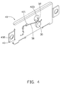
- FIG. 4 is an assembled, isometric view of FIG. 3 .
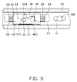
- FIG. 5 is an assembled, side plan view of the second rail, the positioning member, the releasing member, the first resilient member, and the second resilient member of FIG. 2 .
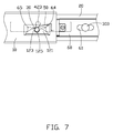
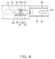
- FIGs. 6-10 are assembled, side plan views of FIG. 2 in different using states.
- an embodiment of a slide rail assembly includes a first rail 10, a second rail 20 slidably received in the first rail 10, a positioning member 30, a mounting bracket 40, a releasing member 60, a first resilient member 50, and a second resilient member 70.
- the first rail 10 defines a substantially C-shaped cross section, and includes a sidewall and top and bottom walls extending from opposite sides of the sidewall.
- a holding portion 12 is formed on the first rail 10 adjacent to an end of the first rail 10.
- the holding portion 12 includes a substantially wedge-shaped first block 121, a substantially wedge-shaped second block 123, which is a mirror image of the first block 121, and a positioning gap 125 defined between the first block 121 and the second block 123.
- the first block 121 and the second block 123 protrude in from the sidewall of the first rail 10.
- the first block 121 and the second block 123 are spaced from and aligned with each other in a longitudinal direction of the first rail 10.
- the first block 121 forms a sliding slope 1211 opposite to the positioning gap 125
- the second block 123 forms a sliding slope 1231 opposite to the positioning gap 125.
- the second rail 20 defines a substantially C-shaped cross section, and includes a sidewall and top and bottom walls extending from opposite sides of the sidewall.
- Two securing posts 28 protrude from the sidewall of the second rail 20, adjacent to an end of the second rail 20.
- a slide slot 24 and three through holes 26 are defined in the sidewall of the second slide rail 20 between the securing posts 28.
- the slide slot 24 is slightly arced.
- Two spaced retaining holes 29 are defined in a middle of the sidewall of the second slide rail 20 in a longitudinal direction of the second rail 20.
- the positioning member 30 is a cylinder defining an annular groove 32 in the circumferential face thereof.
- the mounting bracket 40 includes a plate-shaped main body 42, a pair of ears 43 extending from opposite ends of the main body 42, a top flange 45 extending from a top side of the main body 42, and a bottom flange 46 extending from a bottom side of the main body 42.
- Three retaining tabs 421 slantingly extend from the main body 42 in different directions, and are arrayed in a triangle.
- a guide slot 423 is defined in the main body 42, adjacent to the retaining tabs 421.
- the guide slot 423 is slightly arced, and includes a first end 4231 with greater width and a second end 4232 with a lesser width.
- Each of the ears 43 is slightly raised from the main body 42, and defines a fixing hole 432.
- a long mounting slot 461 is defined at a conjunction of the bottom flange 46 and the main body 42.
- Two spaced stopping blocks 463 extend from a side of the bottom flange 46 bounding the mounting slot 461.
- the first resilient member 50 is a bent metal wire.
- the second resilient member 70 is a coil spring.
- the releasing member 60 is a rectangular piece, and defines two spaced slide slots 61 aligned in a longitudinal direction of the releasing member 60, and a rectangular opening 63 adjacent to an end of the releasing member 60.
- a first driving tab 64 and a second driving tab 65 extend from a bottom side bounding the opening 63, and respectively include a first driving slope 641 and a second driving slope 651 facing each other to cooperatively bound a substantially V-shaped locating notch 645 between the first driving tab 64 and the second driving tab 65.
- a cutout 67 is defined in a bottom side of the releasing member 60, and aligned with the locating notch 645.
- Two protrusions 672 are respectively formed at opposite ends of the cutout 67.
- a grip 69 is attached to an end of the releasing member 60 far away from the opening 63.
- the positioning member 30 is inserted into the guide slot 423 from the fist end 4231 of the guide slot 423, and slid to the second end 4232 of the guide slot 423 with opposite sides bounding the guide slot 43 slidably engaging in the annular groove 32 of the positioning member 30.
- the first resilient member 50 is retained by the retaining tabs 421, with an end of the first resilient member 50 engaging in the annular groove 32 of the positioning member 30 to urge the positioning member 30 towards the second end 4232 of the guide slot 423.
- the releasing member 60 is slidably coupled to the second rail 20, with two studs 300 extending through the slide slots 61 of the releasing member 60 and secured in the corresponding retaining holes 29 of the second rail 20.
- the second resilient member 70 is attached to the releasing member 60, with the second resilient member 70 received in the cutout 67 of the releasing member 60, and the protrusions 672 of the releasing member 60 extending into opposite ends of the second resilient member 70, respectively.
- the mounting bracket 40 assembled with the positioning member 30 and the first resilient member 50, is attached to the second rail 20, with the securing pins 28 respectively riveted in the fixing holes 432 of the ears 43 of the mounting bracket 40, so that he guide slot 423 of the mounting bracket 40 is positioned to extend in a direction transverse to the longitudinal direction of the second slide rail 20.
- the mounting slot 461 of the mounting bracket 40 receives the second resilient member 70. Opposite ends of the second resilient member 70 respectively resist against the stopping blocks 463 of the mounting bracket 40.
- the positioning member 30 extends through the locating notch 645 of the releasing member 60 to be received in the slide slot 24.
- the retaining tabs 421 of the positioning member are received in the through holes 26 of the second rail 20.
- the positioning member 30 is disposed on a bottom of the locating notch 645.
- the second rail 20 is inserted into the first rail 10, and slid leftwards relative to the first rail 10 until the positioning member 30 engages with the first block 121 of the first rail 10.
- the second rail 20 is slid further left, so that the positioning member 30 is driven by the sliding slope 1211 of the first block 121 to move up along the guide slot 423 towards the first end 4231 of the guiding slot 423.
- the first resilient member 50 is deformed.
- the mounting bracket 40 moves with the second rail 20 to make the guide slot 423 of the mounting bracket 40 almost align with the positioning gap 125 of the first rail 10 (shown in the FIG. 7 ).
- the first resilient member 50 is restored to drive the positioning member 30 to slide to the second end 3232 of the guide slot 423, and is retained in the positioning gap 125 of the first rail 10. Therefore, the second rail 20 is stopped from sliding further into or out of the first rail 10.
- the grip 69 (shown in FIGS. 1 and 2 ) is manipulated to slide the releasing member 60 leftwards in the longitudinal direction of the second rail 20.
- the protrusions 672 of the releasing member 60 are moved relative to the stopping blocks 463 of the mounting bracket 40 to press the second resilient member 70.
- the first driving slope 641 of the first driving tab 64 drives the positioning member 30 to slide along the guide slot 423 of the mounting bracket 40 towards the first end 4231 of the guide slot 423.
- the positioning member 30 is disengaged from the positioning gap 125 of the first rail 10.
- the second rail 20 is able to slide further into the first rail 10 to be fully received in the first rail 10.
- the releasing member 60 is released, therefore, the second resilient member 70 is restored to return the releasing member 60 to the original position, where the positioning member 30 is disposed on the bottom of the locating notch 645.
- the second rail 20 is slid rightwards relative to the first rail 10 until the positioning member 30 engages with the second block 123.
- the second rail 20 is slid further right, so that the positioning member 30 is driven by the sliding slope 1231 of the second block 123 to move along the guide slot 423 towards the first end 4231 of the guide slot 423, with the first resilient member 50 being deformed.
- the mounting bracket 40 moves with the second rail 20 to make the guide slot 423 of the mounting bracket 40 almost align with the positioning gap 125 of the first rail 10 (shown in the FIG. 7 ).
- the first resilient member 50 is restored to drive the positioning member 30 to slide to the second end 4232 of the guide slot 423, and retained in the positioning gap 125 of the first rail 10. Therefore, the second rail 20 is stopped from sliding further into or out of the first rail 10.
- the grip 69 (shown in FIGS. 1 and 2 ) is manipulated to slide the releasing member 60 rightwards in the longitudinal direction of the second rail 20.
- the protrusions 672 of the releasing member 60 are moved relative to the stopping blocks 463 of the mounting bracket 40 to press the second resilient member 70.
- the second driving slope 651 of the second driving tab 65 drives the positioning member 30 to slide along the guide slot 423 of the mounting bracket 40 towards the first end 4231 of the guide slot 423.
- the positioning member 30 is disengaged from the positioning gap 125 of the first rail 10. Therefore, the second rail 20 can be slid to the right and removed from the first rail 10.
Landscapes
- Engineering & Computer Science (AREA)
- Microelectronics & Electronic Packaging (AREA)
- Computer Hardware Design (AREA)
- General Engineering & Computer Science (AREA)
- Drawers Of Furniture (AREA)
- Chutes (AREA)
- Seats For Vehicles (AREA)
Applications Claiming Priority (1)
| Application Number | Priority Date | Filing Date | Title |
|---|---|---|---|
| CN201010279735.4A CN102404962B (zh) | 2010-09-13 | 2010-09-13 | 滑轨装置 |
Publications (2)
| Publication Number | Publication Date |
|---|---|
| EP2440027A2 true EP2440027A2 (de) | 2012-04-11 |
| EP2440027A3 EP2440027A3 (de) | 2013-08-21 |
Family
ID=44583938
Family Applications (1)
| Application Number | Title | Priority Date | Filing Date |
|---|---|---|---|
| EP11168550.9A Withdrawn EP2440027A3 (de) | 2010-09-13 | 2011-06-01 | Schienenanordnung |
Country Status (4)
| Country | Link |
|---|---|
| US (1) | US8371542B2 (de) |
| EP (1) | EP2440027A3 (de) |
| JP (1) | JP2012055689A (de) |
| CN (1) | CN102404962B (de) |
Cited By (6)
| Publication number | Priority date | Publication date | Assignee | Title |
|---|---|---|---|---|
| CN104270924A (zh) * | 2014-04-14 | 2015-01-07 | 州巧科技股份有限公司 | 滑轨定位机构 |
| WO2016093796A1 (en) | 2014-12-09 | 2016-06-16 | Hewlett Packard Enterprise Development Lp | Interlock bracket unit |
| EP3082387A1 (de) * | 2015-04-13 | 2016-10-19 | King Slide Works Co., Ltd. | Gleitschienenanordnung |
| CN106136634A (zh) * | 2015-04-23 | 2016-11-23 | 川湖科技股份有限公司 | 滑轨总成 |
| CN108027635A (zh) * | 2015-07-29 | 2018-05-11 | 康普技术有限责任公司 | 刀片机箱系统 |
| EP3598922B1 (de) * | 2018-07-27 | 2021-04-14 | King Slide Works Co., Ltd. | Gleitschienenanordnung |
Families Citing this family (22)
| Publication number | Priority date | Publication date | Assignee | Title |
|---|---|---|---|---|
| CN103491737B (zh) * | 2013-09-17 | 2016-06-29 | 华为技术有限公司 | 一种机柜转接底座 |
| SI2851052T1 (sl) * | 2013-09-24 | 2016-02-29 | Weyergans High Care Ag | Medicinska podtlačna komora s pomično ležalno blazino |
| US9258923B2 (en) * | 2014-01-07 | 2016-02-09 | King Slide Works Co., Ltd. | Adjustable bracket assembly and slide assembly |
| TWM499742U (zh) * | 2015-01-27 | 2015-04-21 | Chenbro Micom Co Ltd | 存取裝置托盤結構 |
| TWI593340B (zh) * | 2015-08-14 | 2017-07-21 | King Slide Works Co | 滑軌總成及其托架裝置 |
| CN106612599B (zh) * | 2015-10-22 | 2019-04-12 | 川湖科技股份有限公司 | 支撑总成及其支撑装置 |
| CN105299045A (zh) * | 2015-11-30 | 2016-02-03 | 英业达科技有限公司 | 轨道机构 |
| CN105425919B (zh) * | 2015-12-17 | 2019-04-16 | 英业达科技有限公司 | 一种服务器系统及其应用的限位机构 |
| TWI568382B (zh) * | 2016-01-22 | 2017-02-01 | 川湖科技股份有限公司 | 滑軌總成及其操作方法 |
| TWI611748B (zh) * | 2016-12-16 | 2018-01-11 | 川湖科技股份有限公司 | 滑軌機構 |
| TWI642386B (zh) * | 2017-08-10 | 2018-12-01 | 川湖科技股份有限公司 | 滑軌總成及其滑軌套件 |
| CN110392503B (zh) * | 2018-04-16 | 2020-11-03 | 鸿富锦精密电子(天津)有限公司 | 滑轨装置 |
| CN109561630B (zh) * | 2019-01-14 | 2021-08-31 | 华北理工大学 | 一种服务器机柜结构 |
| TWI704889B (zh) * | 2019-10-28 | 2020-09-21 | 川湖科技股份有限公司 | 滑軌總成 |
| CN112332180B (zh) * | 2020-11-27 | 2025-06-06 | 町洋机电(中国)有限公司 | 导轨安装支架 |
| CN112987885B (zh) * | 2021-03-02 | 2023-03-14 | 英业达科技有限公司 | 服务器机柜 |
| US11920401B2 (en) | 2021-05-03 | 2024-03-05 | Kohler Co. | Slow close mechanism for sliding applications |
| CN113260215B (zh) * | 2021-06-03 | 2021-10-22 | 苏州浪潮智能科技有限公司 | 一种节点安全锁定装置及服务器 |
| USD1102262S1 (en) * | 2023-06-14 | 2025-11-18 | Nan Juen International Co., Ltd. | Slide rail with locking structure |
| JP2025027652A (ja) * | 2023-08-16 | 2025-02-28 | ブラザー工業株式会社 | 画像形成装置 |
| US20260013067A1 (en) * | 2024-07-05 | 2026-01-08 | Fositek Corporation | Sliding rail device |
| TWI874255B (zh) * | 2024-07-05 | 2025-02-21 | 富世達股份有限公司 | 具有同步擋止機構的滑軌裝置 |
Family Cites Families (8)
| Publication number | Priority date | Publication date | Assignee | Title |
|---|---|---|---|---|
| US6375290B1 (en) * | 2001-09-28 | 2002-04-23 | King Slide Works Co., Ltd. | Lock snap structure of slide rail |
| US6945619B1 (en) * | 2004-08-13 | 2005-09-20 | King Slide Works Co., Ltd. | Positioning device for a slide |
| US7101081B2 (en) * | 2004-10-12 | 2006-09-05 | King Slide Works Co., Ltd. | Positioning device for a ball bearing slide |
| CN101190075B (zh) * | 2006-11-29 | 2010-08-25 | 鸿富锦精密工业(深圳)有限公司 | 滑轨装置 |
| CN101327077B (zh) * | 2007-06-22 | 2010-11-10 | 鸿富锦精密工业(深圳)有限公司 | 滑轨装置 |
| CN101332022B (zh) * | 2007-06-27 | 2010-11-10 | 鸿富锦精密工业(深圳)有限公司 | 滑轨装置 |
| US7758134B2 (en) * | 2007-08-28 | 2010-07-20 | Nan Juen International Co., Ltd. | Drawer fixing apparatus |
| CN201248219Y (zh) * | 2008-07-25 | 2009-05-27 | 鸿富锦精密工业(深圳)有限公司 | 具有卡扣结构的滑轨 |
-
2010
- 2010-09-13 CN CN201010279735.4A patent/CN102404962B/zh active Active
- 2010-12-03 US US12/960,345 patent/US8371542B2/en active Active
-
2011
- 2011-06-01 EP EP11168550.9A patent/EP2440027A3/de not_active Withdrawn
- 2011-08-29 JP JP2011185785A patent/JP2012055689A/ja active Pending
Non-Patent Citations (1)
| Title |
|---|
| None |
Cited By (14)
| Publication number | Priority date | Publication date | Assignee | Title |
|---|---|---|---|---|
| CN104270924B (zh) * | 2014-04-14 | 2017-04-12 | 州巧科技股份有限公司 | 滑轨定位机构 |
| CN104270924A (zh) * | 2014-04-14 | 2015-01-07 | 州巧科技股份有限公司 | 滑轨定位机构 |
| WO2016093796A1 (en) | 2014-12-09 | 2016-06-16 | Hewlett Packard Enterprise Development Lp | Interlock bracket unit |
| EP3231267A4 (de) * | 2014-12-09 | 2017-12-06 | Hewlett-Packard Enterprise Development LP | Verriegelungskonsoleneinheit |
| US10080303B2 (en) | 2014-12-09 | 2018-09-18 | Hewlett Packard Enterprise Development Lp | Interlock bracket unit |
| EP3082387A1 (de) * | 2015-04-13 | 2016-10-19 | King Slide Works Co., Ltd. | Gleitschienenanordnung |
| CN106136634B (zh) * | 2015-04-23 | 2018-12-11 | 川湖科技股份有限公司 | 滑轨总成 |
| CN106136634A (zh) * | 2015-04-23 | 2016-11-23 | 川湖科技股份有限公司 | 滑轨总成 |
| CN108027635A (zh) * | 2015-07-29 | 2018-05-11 | 康普技术有限责任公司 | 刀片机箱系统 |
| EP3329346A4 (de) * | 2015-07-29 | 2019-06-12 | Commscope Technologies LLC | Beschaufelte chassissysteme |
| US11022770B2 (en) | 2015-07-29 | 2021-06-01 | Commscope Technologies Llc | Bladed chassis systems |
| CN108027635B (zh) * | 2015-07-29 | 2021-08-03 | 康普技术有限责任公司 | 刀片机箱系统 |
| US11635579B2 (en) | 2015-07-29 | 2023-04-25 | Commscope Technologies Llc | Bladed chassis systems |
| EP3598922B1 (de) * | 2018-07-27 | 2021-04-14 | King Slide Works Co., Ltd. | Gleitschienenanordnung |
Also Published As
| Publication number | Publication date |
|---|---|
| US8371542B2 (en) | 2013-02-12 |
| US20120061551A1 (en) | 2012-03-15 |
| CN102404962B (zh) | 2016-03-02 |
| JP2012055689A (ja) | 2012-03-22 |
| EP2440027A3 (de) | 2013-08-21 |
| CN102404962A (zh) | 2012-04-04 |
Similar Documents
| Publication | Publication Date | Title |
|---|---|---|
| US8371542B2 (en) | Slide rail assembly | |
| US9820404B1 (en) | Slot assembly and workpiece | |
| US20080124009A1 (en) | Slide rail assembly | |
| US6851773B2 (en) | Retaining structure for a slide-aiding member of a track device for a drawer | |
| US7355846B1 (en) | Mounting device for disk drive | |
| US8310827B2 (en) | Strap mechanism for drawing an electronic device from a cage | |
| US20110043087A1 (en) | Slide rail buffering structure | |
| US20110262060A1 (en) | Sliding mechanism | |
| US20120153792A1 (en) | Slide rail assembly | |
| US7336482B2 (en) | Mounting apparatus for storage device | |
| US20080303398A1 (en) | Slider assembly | |
| US10015892B1 (en) | Disk drive holding mechanism and server using the same | |
| CN103379793A (zh) | 具有卡扣结构的电子装置壳体 | |
| CN101730406B (zh) | 机箱 | |
| US9568071B2 (en) | Chain guide | |
| US7542277B2 (en) | Mounting apparatus for data storage device | |
| US10874023B2 (en) | Reciprocator-type quick-releasing mechanism | |
| CN209781406U (zh) | 弹出装置和显示屏 | |
| US8763967B2 (en) | Mounting apparatus for hard disk drive | |
| TW201424151A (zh) | 電子裝置擴充盒 | |
| CN107783615B (zh) | 硬盘架组件 | |
| US7542278B2 (en) | Electronic apparatus incorporating fixing mechanism | |
| US9329641B2 (en) | Securing structure and an electronic device incorporating the same | |
| JP3241449U (ja) | 解放機構および電子デバイス | |
| US8570733B2 (en) | Fastening device for data storage device |
Legal Events
| Date | Code | Title | Description |
|---|---|---|---|
| AK | Designated contracting states |
Kind code of ref document: A2 Designated state(s): AL AT BE BG CH CY CZ DE DK EE ES FI FR GB GR HR HU IE IS IT LI LT LU LV MC MK MT NL NO PL PT RO RS SE SI SK SM TR |
|
| AX | Request for extension of the european patent |
Extension state: BA ME |
|
| PUAI | Public reference made under article 153(3) epc to a published international application that has entered the european phase |
Free format text: ORIGINAL CODE: 0009012 |
|
| PUAL | Search report despatched |
Free format text: ORIGINAL CODE: 0009013 |
|
| AK | Designated contracting states |
Kind code of ref document: A3 Designated state(s): AL AT BE BG CH CY CZ DE DK EE ES FI FR GB GR HR HU IE IS IT LI LT LU LV MC MK MT NL NO PL PT RO RS SE SI SK SM TR |
|
| AX | Request for extension of the european patent |
Extension state: BA ME |
|
| RIC1 | Information provided on ipc code assigned before grant |
Ipc: A47B 88/08 20060101ALI20130716BHEP Ipc: A47B 88/16 20060101ALI20130716BHEP Ipc: H05K 7/14 20060101AFI20130716BHEP Ipc: H05K 7/18 20060101ALI20130716BHEP |
|
| STAA | Information on the status of an ep patent application or granted ep patent |
Free format text: STATUS: THE APPLICATION IS DEEMED TO BE WITHDRAWN |
|
| 18D | Application deemed to be withdrawn |
Effective date: 20140222 |