EP2440154B1 - Dispositif d'augmentation anatomique - Google Patents
Dispositif d'augmentation anatomique Download PDFInfo
- Publication number
- EP2440154B1 EP2440154B1 EP10721956.0A EP10721956A EP2440154B1 EP 2440154 B1 EP2440154 B1 EP 2440154B1 EP 10721956 A EP10721956 A EP 10721956A EP 2440154 B1 EP2440154 B1 EP 2440154B1
- Authority
- EP
- European Patent Office
- Prior art keywords
- inflatable bladder
- urethra
- conduit
- connection line
- pump
- Prior art date
- Legal status (The legal status is an assumption and is not a legal conclusion. Google has not performed a legal analysis and makes no representation as to the accuracy of the status listed.)
- Active
Links
- 0 C(C1)C2[C@]1*CC2 Chemical compound C(C1)C2[C@]1*CC2 0.000 description 1
Images




Classifications
-
- A—HUMAN NECESSITIES
- A61—MEDICAL OR VETERINARY SCIENCE; HYGIENE
- A61F—FILTERS IMPLANTABLE INTO BLOOD VESSELS; PROSTHESES; DEVICES PROVIDING PATENCY TO, OR PREVENTING COLLAPSING OF, TUBULAR STRUCTURES OF THE BODY, e.g. STENTS; ORTHOPAEDIC, NURSING OR CONTRACEPTIVE DEVICES; FOMENTATION; TREATMENT OR PROTECTION OF EYES OR EARS; BANDAGES, DRESSINGS OR ABSORBENT PADS; FIRST-AID KITS
- A61F2/00—Filters implantable into blood vessels; Prostheses, i.e. artificial substitutes or replacements for parts of the body; Appliances for connecting them with the body; Devices providing patency to, or preventing collapsing of, tubular structures of the body, e.g. stents
- A61F2/0004—Closure means for urethra or rectum, i.e. anti-incontinence devices or support slings against pelvic prolapse
- A61F2/0009—Closure means for urethra or rectum, i.e. anti-incontinence devices or support slings against pelvic prolapse placed in or outside the body opening close to the surface of the body
- A61F2/0013—Closure means for urethra or rectum, i.e. anti-incontinence devices or support slings against pelvic prolapse placed in or outside the body opening close to the surface of the body inflatable
-
- A—HUMAN NECESSITIES
- A61—MEDICAL OR VETERINARY SCIENCE; HYGIENE
- A61F—FILTERS IMPLANTABLE INTO BLOOD VESSELS; PROSTHESES; DEVICES PROVIDING PATENCY TO, OR PREVENTING COLLAPSING OF, TUBULAR STRUCTURES OF THE BODY, e.g. STENTS; ORTHOPAEDIC, NURSING OR CONTRACEPTIVE DEVICES; FOMENTATION; TREATMENT OR PROTECTION OF EYES OR EARS; BANDAGES, DRESSINGS OR ABSORBENT PADS; FIRST-AID KITS
- A61F2/00—Filters implantable into blood vessels; Prostheses, i.e. artificial substitutes or replacements for parts of the body; Appliances for connecting them with the body; Devices providing patency to, or preventing collapsing of, tubular structures of the body, e.g. stents
- A61F2/0004—Closure means for urethra or rectum, i.e. anti-incontinence devices or support slings against pelvic prolapse
- A61F2/0031—Closure means for urethra or rectum, i.e. anti-incontinence devices or support slings against pelvic prolapse for constricting the lumen; Support slings for the urethra
- A61F2/0036—Closure means for urethra or rectum, i.e. anti-incontinence devices or support slings against pelvic prolapse for constricting the lumen; Support slings for the urethra implantable
- A61F2/004—Closure means for urethra or rectum, i.e. anti-incontinence devices or support slings against pelvic prolapse for constricting the lumen; Support slings for the urethra implantable inflatable
-
- A—HUMAN NECESSITIES
- A61—MEDICAL OR VETERINARY SCIENCE; HYGIENE
- A61F—FILTERS IMPLANTABLE INTO BLOOD VESSELS; PROSTHESES; DEVICES PROVIDING PATENCY TO, OR PREVENTING COLLAPSING OF, TUBULAR STRUCTURES OF THE BODY, e.g. STENTS; ORTHOPAEDIC, NURSING OR CONTRACEPTIVE DEVICES; FOMENTATION; TREATMENT OR PROTECTION OF EYES OR EARS; BANDAGES, DRESSINGS OR ABSORBENT PADS; FIRST-AID KITS
- A61F2/00—Filters implantable into blood vessels; Prostheses, i.e. artificial substitutes or replacements for parts of the body; Appliances for connecting them with the body; Devices providing patency to, or preventing collapsing of, tubular structures of the body, e.g. stents
- A61F2/0004—Closure means for urethra or rectum, i.e. anti-incontinence devices or support slings against pelvic prolapse
- A61F2/0031—Closure means for urethra or rectum, i.e. anti-incontinence devices or support slings against pelvic prolapse for constricting the lumen; Support slings for the urethra
- A61F2/0036—Closure means for urethra or rectum, i.e. anti-incontinence devices or support slings against pelvic prolapse for constricting the lumen; Support slings for the urethra implantable
- A61F2/0045—Support slings
-
- A—HUMAN NECESSITIES
- A61—MEDICAL OR VETERINARY SCIENCE; HYGIENE
- A61F—FILTERS IMPLANTABLE INTO BLOOD VESSELS; PROSTHESES; DEVICES PROVIDING PATENCY TO, OR PREVENTING COLLAPSING OF, TUBULAR STRUCTURES OF THE BODY, e.g. STENTS; ORTHOPAEDIC, NURSING OR CONTRACEPTIVE DEVICES; FOMENTATION; TREATMENT OR PROTECTION OF EYES OR EARS; BANDAGES, DRESSINGS OR ABSORBENT PADS; FIRST-AID KITS
- A61F2/00—Filters implantable into blood vessels; Prostheses, i.e. artificial substitutes or replacements for parts of the body; Appliances for connecting them with the body; Devices providing patency to, or preventing collapsing of, tubular structures of the body, e.g. stents
- A61F2/0063—Implantable repair or support meshes, e.g. hernia meshes
Definitions
- Implanting and anatomically securing some sling devices may be difficult and time consuming.
- some sling devices may provide unreliable anatomical fixation and/or imperfect tensioning for supporting the urethra, thereby leading to suboptimal or even unacceptable results for the treatment of urinary incontinence.
- an anatomical augmentation device is known from WO 2005/009293 which discloses an artificial sphincter for treatment of urinary incontinence comprising an urethral implant with an inflatable balloon, a pump with a liquid container and a valve, as well as a flowing duct for the liquid.
- US2005/0055052 discloses a knotless suture anchor that includes an inner member including a proximal shaft and a distal securing member shaped to secure the inner member to the tissue, the proximal shaft including a first locking part and at least one hole extending therethrough for receiving the suture thread; and a collar member including an axial bore shaped to receive the proximal shaft of the inner member, a second locking part, and at least one hole extending therethrough and assigned to the hole of the proximal shaft of the inner member.
- Soft tissue includes dermal tissue, sub-dermal tissue, ligaments, tendons, or membranes but does not include bone.
- Embodiments provide an anatomical augmentation device configured to selectively occlude a tubular member of a human body (male or female) in a manner that reduces or eliminates erosion of the tubular member.
- One embodiment provides an anatomical device implantable into a patient that enables the patient to urinate freely after the patient activates a mechanical component of the anatomical device. In this manner, the patient is empowered to control urine retention and urine voiding.
- FIG 2 is a schematic cross-sectional view of pump 22 according to one embodiment.
- Pump 22 includes a bulb 60 sized to retain a liquid volume V and a valve housing 62 extending between bulb 60 and pump conduit 50.
- bulb 60 is formed of silicone and includes an articulated housing 70 that is configured to be sufficiently resilient to enable a patient to expel a sufficient volume of liquid from bulb 60 to inflate inflatable bladder 26.
- bulb 60 is sufficiently resilient to enable the patient to expel a sufficient volume of liquid from bulb 60 to inflate inflatable bladder 26 with one squeeze.
- Suitable liquids to be retained in bulb 60 for activating inflatable bladder 26 include fluids in general, examples of which include water or a saline solution of water.
- the liquid is a sterile saline solution.
- valve housing 62 encloses a ball valve 80 or check valve 80, a biasing member 82, and a seat 84 sized to receive ball valve 80.
- compressing bulb 60 ejects the liquid volume V into or toward pump conduit 50 with sufficient force to lift ball valve 80 off of seat 84.
- Biasing member 82 is subsequently compressed, which provides a fluid passageway between ball valve 80 and seat 84 that allows the liquid inside of bulb 60 to flow through pump conduit 50 and inflate inflatable bladder 26 ( Figure 1 ).
- bulb 60 When the pressure (e.g., squeeze) applied to bulb 60 is relieved, biasing member 82 biases ball valve 80 back into engagement with seat 84, which closes the fluid passageway between ball valve 80 and seat 84 to ensure that the liquid remains in inflatable bladder 26 and inflatable bladder 26 remains inflated.
- bulb 60 is "cavitated” to have a lower pressure than the pressure in inflatable bladder 26, which "primes” bulb 60 to eventually suction or pull the liquid from inflatable bladder 26 back into bulb, 60 when ball valve 80 is displaced from seat 84, for example when the patient desires to deflate inflatable bladder 26.
- conduit 28 between pump 22 and inflatable bladder 26 is provided in a fixed length such that pump conduit 50 and inflatable bladder conduit 52 are formed as a single integral conduit.
- support 24 of anatomical augmentation device 20 ( Figure 1 ) is fixed in place relative to the urethra, and inflating inflatable bladder 26 ( Figure 3A ) compresses and coaptates the urethra.
- a patient may desire to close or coaptate the urethra (by squeezing bulb 60 in Figure 2 ) during the daytime active period.
- Deflating inflatable bladder 26 as illustrated in Figure 3B collapses bladder 26 toward support 24, which decompresses bladder 26 and enables the urethra to return to its open position.
- a patient may open the urethra (by pressing relief feature 86 in Figure 2 ) to void urine, or during the nighttime sleep period when the urge to void is reduced.
- FIG 4 is a perspective view of an anatomical augmentation device 100 according to one embodiment.
- Anatomical augmentation device 100 (device 100) includes a pump 102, a support 104 coupled to an inflatable bladder 106, and a conduit 108 providing fluid communication between pump 102 and inflatable bladder 106.
- pump 102 is similar to pump 22 ( Figure 2 ) and includes a bulb 110 of volume V, a valve housing 112 extending between bulb 110 and a pump conduit 114, where valve housing 112 includes a pressure relief feature 116 similar to pressure relief feature 86 described above in Figure 2 .
- support 104 is a mesh configured to be compatible with and enable tissue in-growth to the mesh to additionally support/retain device 100 after implantation.
- One suitable mesh is a knitted polypropylene mesh. Other suitable meshes are also acceptable for use as support 104.
- support 104 is substantially the same size as inflatable bladder 106. In one embodiment, support 104 is substantially different in size as compared to inflatable bladder 106
- At least one of the anchors 140, 142 is an adjustable anchor that is configured to slide along a respective one of the connection lines 120, 130 to enable selective positioning and tensioning of support 104 and bladder 106 anatomically within a patient.
- adjustable anchor 140 slides along connection line 120 to enable elevating the urethra.
- adjustable anchor 140 slides along connection line 120 to desirably elevate the urethra without compressing the urethra.
- adjustable anchor 140 enables elevating the urethra with approximately zero tension applied to the urethra.
- adjustable anchor 140 in one embodiment is configured to slide along connection line 120 to both elevate and apply tension to the urethra.
- adjustable anchor 140 slides along connection line 120 to desirably elevate and apply tension to the urethra.
- a length of line 120 is between 2-20 cm, approximately, and a length of connection line 130 is between 0.5-2 cm, approximately.
- the length of line 130 is selected such that when anchor 142 is secured to soft tissue, an approximate mid-point of inflatable bladder is disposed adjacent the patient's urethra.
- Adjustable anchor 140 enables the selective adjustment of the length of line 120 between end 122 of support 104 and anchor 140 to enable the surgeon to position and tension support 104 and bladder 106 to desired levels.
- FIG 5A is an exploded perspective view and Figure 5B is a top view of adjustable anchor 140 and connection line 120 illustrated in Figure 4 according to one embodiment.
- Adjustable anchor 140 includes a body 150 and a collar 152 sized to frictionally capture connection line 120 against body 150.
- Other forms of adjustable anchor 140 configured to frictionally capture and engage with connection line 120 are also acceptable.
- Various such adjustable anchors are disclosed in, for example, co-pending and commonly assigned U.S. non-provisional patent application Serial No. 12/414,709 , having Attorney Docket No. 2009005-US2 and entitled Implantable Devices for Treatment of Urinary Incontinence, filed on March 31, 2009.
- body 150 defines a through-channel 154 and a plurality of flanges 156 protruding from a distal end 158 of body 150 and separated by webs 160.
- collar 152 defines apertures 162a,b that permit frictional sliding engagement and passage of connection line 120 between body 150 and collar 152.
- connection line 120 is disposed through a first aperture 162a of collar 152, around a partial circumference of body 150, and through a second aperture 162b of collar 152. Thus, line 120 contacts both body 150 and collar 152.
- Body 150 and collar 152 exert a compressive force on connection line 120, which causes frictional interference between connection line 120, body 150, and collar 152.
- Adjustable anchor 140 is configured to slide bi-directionally along connection line 120 when a sufficient force is applied to adjustable anchor 140 to overcome the frictional interference of its contacting components.
- an amount of compressive force and thus the desired frictional interference between connection line 120, body 150, and collar 152 can be selectively varied through an appropriate selection of material composition and geometry.
- the compressive force and the frictional interference between connection line 120, body 150, and collar 152 can be selectively varied by fitting collar 152 more tightly against line 120 and body 150.
- apertures 162a,b are spaced farther apart in one embodiment of anchor 140 than in a second embodiment of anchor 140, then the compressive force and resulting frictional interference of the first embodiment would be greater than that of the second embodiment due to, comparatively, a longer contact path between connection line 120 and body 150/collar 152.
- both anchors 140, 142 are provided as adjustable anchors that are configured to slide along the respective one of the connection lines 120, 130 to enable selective positioning of support 104 and bladder 106 anatomically within a patient.
- Figure 6A is a perspective view and Figure 6B is a cross-sectional view of connector 172 employed to couple pump conduit 114 to bladder conduit 170.
- connector 172 includes a body 174 and collets 176 (one of which is shown in Figure 6A ).
- Body 174 includes a radial flange 178, a tubular cage 180 on each side of radial flange 178 that terminates in an end ring 181, where each tubular cage 180 is provided with one or more chucks 182.
- Each of the collets 176 is configured to slide over a section of conduit 114, 170 and onto the tubular cage 180, which will displace the chucks 182 radially inward to exert radial compression onto conduits 114,170.
- a mandrel 183 extends from each opposing face of radial flange 178, and flange 178 includes an undercut surface 184 configured to provide a stop for the ends of the inserted conduits 114, 170.
- Mandrels 183 are sized to fit inside an inside diameter of each conduit 114, 170 to establish a flow path through connector 172.
- End rings 181 are sized to surround an outside diameter of conduits 114, 170.
- tubular cage 180 defines clearance apertures 186 adjacent to radial flange 178.
- end rings 181 include grooves 188 that provide webs 190 of reduced thickness between end rings 181 and chuck 182, thereby forming a flexible hinge that enables inward deflection of chucks 182 as collets 176 are advanced over tubular cages 180. For example, after the surgeon cuts conduits 114, 170 to a desired length, one of the collets 176 is placed over each of the conduits 114, 170 and mandrels 183 are inserted into conduits 114, 170.
- conduits 114, 170 are seated against radial flange 178, and the collets 176 are slid over tubular cages 180 and conduits 114, 170.
- the collets 176 deflects chucks 182 inward to exert a radial pinching force around a periphery of conduits 114, 170, which forms a durable connection between the two spliced conduits 114, 170.
- Augmentation devices 20,100 are implantable into a human body of a patient to enable the patient to controllably impede liquid flow through their urethra or other duct.
- the compact size and limited number of components of the augmentation devices 20, 100 enable the surgeon to implant the devices in a short time frame that has the potential to limit the time, expense, and known side-effects and risks associated with other longer surgical urinary incontinence procedures.
- Figure 7 is a flow diagram 200 of a method of surgically implanting one of the augmentation devices 20, 100 into a patient according to one example.
- the method includes creating a perineal incision at 202. In one example, a single perineal incision is created allowing direct access for the surgeon to place the augmentation devices 20, 100 near the patient's urethra.
- the method includes inserting a support supporting an inflatable bladder into the patient through the perineal incision.
- the method includes securing the support between two opposing obturator membranes such that the inflatable bladder is spaced apart from the urethra.
- the inflatable bladder is spaced apart from the bulbous spongiosum that surrounds urethra, which avoids having to separate the bulbous spongiosum from the urethra, thus providing shorter surgical time than is conventional with other incontinence-correcting procedures.
- the method includes inserting a pump inside of the scrotum, the pump communicating with the inflatable bladder.
- Figure 8 is a flow diagram 210 of a method of providing a patient with continence control according to one example.
- the method includes surgically implanting a urethra augmentation device into the patient at 212.
- one of the augmentation devices 20, 100 is implanted preferably via a single perineal incision as referenced above such that support 104 of the device is near or adjacent to the patient's urethra.
- the method includes selectively coaptating a urethra of the patient with the urethra augmentation device.
- the patient squeezes bulb 110 of pump 102 to inflate inflatable bladder 106 with liquid from bulb 110.
- the method includes enabling the patient to urinate via patient-activation of a component of the urethra augmentation device.
- the patient activates the pressure relief feature 116 to permit the liquid within inflatable bladder 106 to return to bulb 110, thus deflating the inflatable bladder 106, Deflation of inflatable bladder 106 allows the patient's urethra to open for the passage of urine.
- Figure 9A is a schematic diagram of anatomical augmentation device 100 anchored to obturator tissue OT of a male patient with inflatable bladder 106 deflated and positioned relative to the patient's urethra U according to one embodiment.
- support 104 of device 100 is implanted in a pelvic region PR through a single perineal incision, and pump 102 is implanted in the patient's scrotum S by blunt dissection of the scrotum S.
- Fixed anchor 142 is secured to obturator tissue OT of one obturator foramen OF and adjustable anchor 140 is secured to obturator tissue OT in the other obturator foramen OF.
- both anchors 140, 142 are configured as adjustable anchors.
- Flanges 156 secure anchors 140, 142 to the obturator tissue OT to maintain device 100 in position relative to urethra U.
- Implantation of device 100 results in support 104 positioned under the bulbous spongiosum BS surrounding the patient's urethra U.
- the bulbous spongiosum BS is not dissected off of the urethra, and inflatable bladder 106 configured to enable patient-control of device 100 to selectively coaptate the urethra U through the surrounding bulbous spongiosum BS.
- positions of anchors 140, 142 could be exchanged in a left and right sense relative to pelvic region PR.
- a tool 220 is employed to implant device 100 in a patient.
- a pair of such tools 220 is employed, including a left hand tool and a right hand tool 220 (illustrated), with such designations referring to a patient's left and right sides, respectively.
- the tools are identical except for a direction of each tool's helical curve C.
- Tool 220 includes a handle 222 coupled to a shaft 224 having a proximal end 226 and a cylindrical distal tip 228.
- Handle 222 may have any desired shape or configuration with respect to ergonomic and other considerations of interest.
- a generally helical curve C is provided in shaft 224.
- Helical curve C terminates in a shoulder 230 proximate to distal tip 228.
- helical curve C is advantageously configured to guide tip 228 from an incision (e.g., a vaginal incision in a female patient or a perineal incision in a male patient), around a descending pubic ramus PR, and through obturator foramen OF in the patient.
- cylindrical distal tip 228 is configured to be placed through cylindrical channels 154 of adjustable anchor 140 and fixed anchor 142. When so placed, shoulder 230 abuts the body of anchor 140 adjacent to flanges 156 and anchor 140 is thereby carried on tip 228 of tool 220.
- handle 222 has a length of 11.43 cm (4.5 in.); a length of shaft 610, from handle 620 to a beginning point 232 of curve C is 17.78 cm (7.0 in.); shaft 224 has a diameter of 3 mm (0.12 in.) decreasing to 1 mm (0.04 in.) at shoulder portion 230; and curve C has a radius of curvature in a range of 2.03 cm (0.80 in.) to 2.54 cm (1.0 in.).
- Suitable materials for construction of handle 222 include, for example, thermoplastic or thermoset material, preferably having both high and low durometer regions for ergonomic considerations.
- a suitable material for construction of shaft 610 is, for example, stainless steel.
- Tool 200 is disposable, or alternatively, sterilizable and reusable.
- a length of distal tip 228 is chosen so that it protrudes from anchor 140 seated on shoulder 230.
- relatively stiff tip 228 is thereby configured to pierce tissue.
- a catheter is placed in the patient's urethra U, among other usual and preliminary steps in preparation for surgery.
- the patient is placed on an operating table in a slightly exaggerated lithotomy position with buttocks extending just beyond an edge of the table.
- a vaginal incision female
- a perineal incision male
- blunt dissection is made in one example of the method.
- fixed anchor 142 is first placed in obturator tissue OT on the patient's left side, followed by placement of support 104, with subsequent placement of adjustable anchor 142 in obturator tissue OT on the patient's right side.
- fixed anchor 142 is placed on distal tip 228 of a left hand tool having an orientation of helical curve C configured to correspond to the patient's left side. Tip 228 of left hand tool, with fixed anchor 142 seated thereupon, is placed within the incision. Left hand tool is then rotated such that rotation of helical curve C advances tip 228 and fixed anchor 142 in a path around a descending pubic ramus PR on the patient's left side, continuing in that path until fixed anchor 142 penetrates obturator tissue OT on the patient's left side (as may be indicated by an audible or tactile "pop") to indicate fixed anchor 142 has thus been secured in obturator tissue OT. Fixed anchor 142 is inhibited from being pulled back through obturator tissue OT by virtue of flanges 156. Left hand tool is then removed from the patient.
- adjustable anchor 140 is placed on distal tip 228 of right hand tool 200 having an orientation of helical curve C corresponding to the patient's right side.
- Tip 228 of right hand tool 200, with adjustable anchor 140 seated thereupon, is placed within the incision.
- Right hand tool 200 is then rotated such that rotation of helical curve C advances tip 228 and adjustable anchor 140 in a path around a descending pubic ramus (PR) on the patient's right side, continuing in that path until adjustable anchor 140 penetrates obturator tissue OT on the patient's right side (as indicated by an audible or tactile "pop") to indicate adjustable anchor 140 has thus been secured in obturator tissue OT.
- Adjustable anchor 140 its inhibited from being pulled back through obturator tissue OT by virtue of flanges 156.
- Right hand tool 600R is then removed from the patient.
- Device 100 is preferably placed with inflatable bladder 106 deflated. With device 100 thus placed and secured in the patient by way of fixed anchor 142 and adjustable anchor 140, an assessment is made of whether support 104 is unacceptably loose or tight under urethra U. If support 104 is unacceptably loose, then an end of connection line 120 is pulled away from adjustable anchor 140 with a force sufficient to overcome the aforementioned interference force between connection line 120 and adjustable anchor 140. Connection line 120 thus passes through anchor 140 with a resultant shortening of a distance between support 104 and adjustable anchor 140. Thereby support 104 is raised or elevated under urethra U as desired.
- the above-recited process of shortening and lengthening a distance between support 104 and adjustable anchor 140 may be repeated in any order and as frequently as necessary to provide optimal sub-urethral support from support 104 to urethra U.
- the incision is subsequently closed and usual post-operative procedures are performed.
- a volume of liquid is post-surgically injected into bulb 110 and inflatable bladder 106 is inflated sufficiently to occlude urethra U.
- the surgeon may choose to adjust the volume of liquid in bulb 110 at this stage to control the rate and pressure of the inflation of inflatable bladder 106.
- Device 100 enables the surgeon to selectively adjust the location of support. 104 relative to urethra U.
- the distance between the obturator foramen OF and the urethra will vary by individual, and device 100 desirably provides the surgeon with adjustability to accommodate the different sizes of these individuals.
- Figure 9B is a schematic side view of the implanted anatomical augmentation device 100 illustrating pump 102 located inside scrotum S;
- Support 104 provides support to urethra U, the portion of which that it is desirable to support being generally located distal of scrotum S.
- conduit 108 extends from support 104 and inflatable bladder 106 at an angle A relative to a base of support 104 to comfortably and efficaciously locate pump 102 in scrotum S (proximal to support 104) without binding urethra U.
- the angle A ranges from approximately zero degrees to approximately 90 degrees.
- conduit 108 is flexible to enable the surgeon to selectively adjust the angle A between approximately 0-90 degrees.
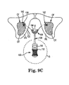
- Figure 9C is a schematic diagram of anatomical augmentation device 100 with inflatable bladder 106 inflated to coaptate the patient's urethra U according to one embodiment.
- anchors 140, 142 secure support 104 in the desired surgeon-located position relative to the urethra U.
- support 104 is formed of an open mesh that is configured to enable tissue in-growth over a short period of patient healing time, which further contributes to desirably fixing device in the surgeon-located position.
- the patient controls the amount of inflation of inflatable bladder 106.
- bulb 110 has been compressed, the compression of which injects liquid from bulb 110 into inflatable bladder 106, thus inflating bladder 106 and compressing urethra U.
- the resiliency of bulb 110 and the liquid volume of, for example, sterile saline within bulb 106 is configured to enable the patient to inflate inflatable bladder 106 with one squeeze of bulb 110 to a level that is sufficient to coaptate urethra U. In this manner, the patient controls the closing of urethra U and thus controls continence.
- the patient is also in control of opening the urethra U, either for nighttime comfort when the urge to void is reduced or forpassing urine.
- ball valve 80 is displaced from seat 84 ( Figure 2 ) to provide a pathway for the liquid inside inflatable bladder 106 to flow down into bulb 110, thus deflating inflatable bladder 106 and opening urethra U.
- Selectively deflating bladder 106 during the nighttime when the urge to void is reduced has the added benefit of reducing compression of the urethra when such compression isn't desired by the patient or anatomically called for. Thus, erosion of the urethra is reduced or eliminated.
- bulb 110 is suited for receiving additional liquid volume post-surgically, for example by a physician who delivers additional liquid to bulb 110 through the scrotum S via a needle/syringe.
- one embodiment of bulb 110 includes a self-sealing port that is punctured to receive additional liquid delivered through the scrotum S via a needle/syringe, where the self-sealing port seals the puncture opening when the syringe is removed.
- Figures 10A-11B illustrated various embodiments of inflatable supports for other embodiments of augmentation devices, the supports configured for connection with pump 22 illustrated in Figure 2 and suited for coaptating a tubular flow member in a human body.
- Figure 10A is a perspective view of one embodiment of an implantable device 250 including an inflatable member 252 in a deflated state
- Figure 10B is a perspective view of implantable device 250 illustrating inflatable member 252 in an inflated state
- Device 250 provides a rectilinear flat pillow form and includes an inflatable member 252 and a conduit 254 in fluid communication with inflatable member 252.
- device 250 is integrally molded to provide a linear (i.e., flat) inflatable member 252 that is suitably supported with connection lines similar to lines 30, 40 ( Figure 1 ).
- device 250 includes a linear inflatable member that is supported by a polymer mesh in a manner similar to how bladder 106 ( Figure 4 ) is supported by mesh support 104 ( Figure 4 ).
- device 260 is integrally molded to provide a linear (i.e., flat) inflatable member 262 that is suitably supported with connection lines similar to lines 30, 40 ( Figure 1 ).
- device 260 includes a linear inflatable member that is supported by a polymer mesh in a manner similar to how bladder 106 ( Figure 4 ) is supported by mesh support 104 ( Figure 4 ).
- inflatable member 262 inflates and region R expands disproportionally greater than the remaining portion of inflatable member 262 to provide compression to tubular members when inflated with a volume V of liquid.
- Figures 12A and 12B are schematic diagrams of a portion of a pair of anatomical augmentation devices 100a, 100b as illustrated in Figure 4 employed as an artificial sphincter disposed around a urethra according to one embodiment.
- Some patients may experience damage to their urethra arising from accident or disease, which can result in an inability to close the urethra. Severe cases of the inability to close the urethra result in a "straight-pipe" condition where the urine flows freely from a non-closable the urethra.
- the "straight-pipe" urethra condition can be repaired by reconstructive surgery, which can be expensive and painful and perhaps provide only short-term or temporary relief.
- FIG 12B illustrates inflation of each inflatable bladder 106 to bi-laterally close urethra U.
- the patient squeezes each bulb 110 ( Figure 4 ) to inflate inflatable bladder 106 as described above.
- the two opposed inflatable bladders 106 expand and combine to compress opposing sides of the bulbous spongiosum and the urethra, thereby offering the patient a patient-controlled sphincter disposed around urethra.
- Undesirable erosion of the urethra due to wear-induced contact with a foreign object is reduced or eliminated since each inflatable bladder 106 is configured to be placed or offset away from the urethra.
Landscapes
- Health & Medical Sciences (AREA)
- Urology & Nephrology (AREA)
- Life Sciences & Earth Sciences (AREA)
- Animal Behavior & Ethology (AREA)
- Engineering & Computer Science (AREA)
- Biomedical Technology (AREA)
- Heart & Thoracic Surgery (AREA)
- Vascular Medicine (AREA)
- Oral & Maxillofacial Surgery (AREA)
- Transplantation (AREA)
- General Health & Medical Sciences (AREA)
- Public Health (AREA)
- Veterinary Medicine (AREA)
- Cardiology (AREA)
- Prostheses (AREA)
- External Artificial Organs (AREA)
Claims (14)
- Dispositif d'augmentation anatomique (20, 100) configuré pour augmenter un organe tubulaire d'un corps humain, le dispositif comprenant :une vessie gonflable (26) ;un support (24) accouplé à la vessie gonflable (26), le support (24) comprenant une première ligne de connexion (30, 120) et une seconde ligne de connexion (40, 130), lesquelles peuvent être attachées à un tissu mou pour positionner la vessie gonflable (26) par rapport à l'organe tubulaire du corps humain, un premier ancrage (140) étant accouplé à la première ligne de connexion (30, 120) et un deuxième ancrage (142) étant accouplé à la deuxième ligne de connexion (40, 130), au moins l'un des ancrages (140, 142) pouvant être ajusté en position par rapport à sa ligne de connexion (30, 120, 40, 130) etcomprenant un corps (150) et un col (152) dimensionné pour serrer par friction l'une des première et seconde lignes de connexion (30, 120, 40, 130) contre le corps (150) ; etune pompe (22) pouvant être accouplée à la vessie gonflable (26) ;le dispositif (20, 100) comprenant un dispositif pouvant être implanté dans le corps et la pompe (22) étant configurée pour gonfler de manière sélective la vessie gonflable (26) afin de fermer l'organe tubulaire du corps humain,caractérisé en ce queledit au moins un ancrage de position ajustable (140, 142) est configuré pour glisser dans deux directions le long de ladite ligne de connexion (30, 120, 40, 130) lorsqu'une force suffisante est appliquée audit ancrage ajustable (140, 142) pour surmonter l'interférence par friction de ces composants de contact.
- Dispositif selon la revendication 1, dans lequel la pompe (22) est configurée pour gonfler de manière sélective la vessie gonflable (26) pour empêcher l'écoulement de liquide à travers un urètre.
- Dispositif selon la revendication 1 ou 2, dans lequel le support (24) et la vessie gonflable (26) comprennent une seule unité formée intégralement.
- Dispositif selon la revendication 1, 2 ou 3, dans lequel le support (24) comprend un treillis chirurgical (104) avec la première ligne de connexion (120) accouplée à une première extrémité (122) du treillis chirurgical (104) et la deuxième ligne de connexion (130) accouplée à une deuxième extrémité (132) du treillis chirurgical (104).
- Dispositif selon l'une quelconque des revendications 1 à 4, dans lequel l'organe tubulaire du corps humain est un urètre et l'ancrage ajustable (140, 142) est configuré pour ajuster de manière sélective au moins l'une parmi une élévation du support (24) par rapport à l'urètre et une tension du support (24) par rapport à une portion de l'urètre.
- Dispositif selon l'une quelconque des revendications 1 à 5, dans lequel les première et deuxième lignes de connexion (30, 120, 40, 130) peuvent chacune être attachées à un tissu obturateur pour positionner la vessie gonflable (26) par rapport à un tissu bulbeux entourant un urètre, la vessie gonflable (26) étant moulée de manière à comprendre une courbure arquée qui est configurée pour comprimer le tissu bulbeux et l'urètre afin d'empêcher l'écoulement de liquide à travers l'urètre.
- Dispositif selon l'une quelconque des revendications 1 à 6, dans lequel la pompe (22) comprend :une partie en forme de bulbe (60) ;un logement de soupape (62) accouplé à la partie en forme de bulbe (60) ; etun conduit (50) accouplé au boîtier de soupape (62) et configuré pour assurer la communication fluidique avec la vessie gonflable (26) ;la partie en forme de bulbe (60) comprenant une partie en forme de bulbe élastique telle qu'une compression de la partie en forme de bulbe provoque l'éjection d'une partie du volume de fluide à travers le conduit (50) en vue de gonfler la vessie gonflable (26).
- Dispositif selon la revendication 7, dans lequel la partie en forme de bulbe (60) de la pompe (22) est dimensionnée de manière à permettre l'implantation dans un scrotum.
- Dispositif selon la revendication 8, dans lequel l'organe tubulaire du corps humain est un urètre et une compression unique de la partie en forme de bulbe (60) gonfle la vessie gonflable (26) pour coapter l'urètre.
- Dispositif selon la revendication 8 ou 9, dans lequel le boîtier de soupape (62) comprend un clapet anti-retour (80) configuré pour permettre de manière sélective l'écoulement du volume de fluide depuis la vessie gonflable (26) jusqu'à la partie en forme de bulbe (60).
- Dispositif selon la revendication 8, 9 ou 10, dans lequel la vessie gonflable (26) comprend un deuxième conduit (52) pouvant être accouplé au conduit (50) de la pompe (22) par le biais d'un dispositif d'interconnexion verrouillable.
- Dispositif selon la revendication 11, dans lequel le deuxième conduit (52) s'étend depuis la vessie gonflable (26) suivant un angle non perpendiculaire à une base de la vessie gonflable (26) .
- Kit de pièces comprenant :une vessie gonflable (26) comprenant un conduit de vessie (52) ;un support (24) accouplé à la vessie gonflable (26) et comprenant une première ligne de connexion (30, 120) et une deuxième ligne de connexion (40, 130), un premier ancrage (140) accouplé à la première ligne de connexion (30, 120) et un deuxième ancrage (142) accouplé à la deuxième ligne de connexion (40, 130), au moins l'un des ancrages (140, 142) pouvant être ajusté en position par rapport à sa ligne de connexion (30, 120, 40, 130) ;une pompe (22) pouvant être accouplée à la vessie gonflable (26), la pompe (22) comprenant un conduit de pompe (50) ; etun dispositif de fixation configuré pour connecter le conduit de vessie (52) au conduit de pompe (50), au moins l'un des ancrages (140, 142) comprenant un corps (150) et un col (152) dimensionné pour serrer par friction l'une des première et seconde lignes de connexion (30, 120, 40, 130) contre le corps (150),caractérisé en ce queledit au moins un ancrage de position ajustable (140, 142) est configuré pour glisser dans deux directions le long de ladite ligne de connexion (30, 120, 40, 130) lorsqu'une force suffisante est appliquée audit ancrage ajustable (140, 142) pour surmonter l'interférence par friction de ces composants de contact.
- Kit de pièces selon la revendication 13, dans lequel le dispositif de fixation comprend :une première cage tubulaire (180) configurée pour être disposée par-dessus un diamètre extérieur du conduit de vessie (52) et une deuxième cage tubulaire (180) configurée pour être disposée par-dessus un diamètre extérieur du conduit de pompe (50) ; etun premier collet (176) configuré pour comprimer radialement la première cage tubulaire (180) sur le diamètre extérieur du conduit de vessie (52) etun deuxième collet (176) configuré pour comprimer radialement la deuxième cage tubulaire (180) sur le diamètre extérieur du conduit de pompe (50).
Priority Applications (1)
| Application Number | Priority Date | Filing Date | Title |
|---|---|---|---|
| EP13191522.5A EP2700383B1 (fr) | 2009-06-08 | 2010-06-08 | Dispositif d'augmentation anatomique |
Applications Claiming Priority (2)
| Application Number | Priority Date | Filing Date | Title |
|---|---|---|---|
| DKPA200900718A DK200900718A (en) | 2009-06-08 | 2009-06-08 | Anatomical augmentation device |
| PCT/DK2010/050128 WO2010142294A1 (fr) | 2009-06-08 | 2010-06-08 | Dispositif d'augmentation anatomique |
Related Child Applications (1)
| Application Number | Title | Priority Date | Filing Date |
|---|---|---|---|
| EP13191522.5A Division EP2700383B1 (fr) | 2009-06-08 | 2010-06-08 | Dispositif d'augmentation anatomique |
Publications (2)
| Publication Number | Publication Date |
|---|---|
| EP2440154A1 EP2440154A1 (fr) | 2012-04-18 |
| EP2440154B1 true EP2440154B1 (fr) | 2013-11-20 |
Family
ID=42731881
Family Applications (2)
| Application Number | Title | Priority Date | Filing Date |
|---|---|---|---|
| EP10721956.0A Active EP2440154B1 (fr) | 2009-06-08 | 2010-06-08 | Dispositif d'augmentation anatomique |
| EP13191522.5A Active EP2700383B1 (fr) | 2009-06-08 | 2010-06-08 | Dispositif d'augmentation anatomique |
Family Applications After (1)
| Application Number | Title | Priority Date | Filing Date |
|---|---|---|---|
| EP13191522.5A Active EP2700383B1 (fr) | 2009-06-08 | 2010-06-08 | Dispositif d'augmentation anatomique |
Country Status (8)
| Country | Link |
|---|---|
| US (3) | US8617050B2 (fr) |
| EP (2) | EP2440154B1 (fr) |
| CN (1) | CN102458301B (fr) |
| BR (1) | BRPI1012961B1 (fr) |
| DK (1) | DK200900718A (fr) |
| ES (2) | ES2445147T3 (fr) |
| RU (1) | RU2543032C2 (fr) |
| WO (1) | WO2010142294A1 (fr) |
Families Citing this family (16)
| Publication number | Priority date | Publication date | Assignee | Title |
|---|---|---|---|---|
| EP2536350A4 (fr) * | 2010-02-18 | 2015-12-23 | Univ Texas | Prothèse urétrale implantable ayant un élément gonflable |
| US8784296B2 (en) | 2010-09-07 | 2014-07-22 | Coloplast A/S | Angled surgical introducer |
| US8979733B2 (en) | 2011-09-23 | 2015-03-17 | Coloplast A/S | Synthetic urethra with closure device |
| US8758218B2 (en) | 2012-04-20 | 2014-06-24 | Coloplast A/S | Method of treating incontinence and treatment device including non-porous cuff and extending members |
| US8678996B2 (en) * | 2012-05-01 | 2014-03-25 | Coloplast A/S | Incontinence treatment device including non-porous sub-urethral sling |
| US9814554B2 (en) * | 2013-06-06 | 2017-11-14 | Coloplast A/S | Artificial urinary sphincter system |
| US8939889B1 (en) * | 2013-08-22 | 2015-01-27 | Coloplast A/S | Pump bulb for an implantable penile prosthetic |
| US9713518B2 (en) | 2013-12-09 | 2017-07-25 | Boston Scientific Scimed, Inc. | Sacrocolopopexy implants and related methods of use |
| US9918732B2 (en) * | 2013-12-10 | 2018-03-20 | Boston Scientific Scimed, Inc. | Sacrocolopopexy implants and methods of using and manufacturing thereof |
| CN106456306B (zh) * | 2014-06-27 | 2018-12-14 | 安东尼奥·桑布瑟蒂 | 人造括约肌 |
| US9993322B2 (en) * | 2015-05-27 | 2018-06-12 | Coloplast A/S | Method of implanting a urinary control system through a single skin incision |
| EP3384875B1 (fr) | 2017-04-05 | 2021-12-22 | Coloplast A/S | Implant pénien avec tube réglable en longueur |
| US11234824B2 (en) | 2019-05-08 | 2022-02-01 | Boston Scientific Scimed, Inc. | Pump bulb with control features |
| US11614083B2 (en) * | 2019-09-10 | 2023-03-28 | GM Global Technology Operations LLC | Internally tensioned inflatable structure that is posable in multiple positions |
| US11690702B2 (en) | 2020-01-30 | 2023-07-04 | Rambam Medtech Ltd. | Urinary catheter prostheses |
| USD1086084S1 (en) | 2023-12-11 | 2025-07-29 | Coloplast A/S | Deflation button of an implantable penile prosthesis pump |
Citations (1)
| Publication number | Priority date | Publication date | Assignee | Title |
|---|---|---|---|---|
| US20050055052A1 (en) * | 2003-09-10 | 2005-03-10 | Linvatec Corporation | Knotless suture anchor |
Family Cites Families (60)
| Publication number | Priority date | Publication date | Assignee | Title |
|---|---|---|---|---|
| US3863622A (en) * | 1973-01-09 | 1975-02-04 | Robert Enno Buuck | Incontinence system and methods of implanting and using same |
| US4222377A (en) * | 1977-06-27 | 1980-09-16 | American Medical Systems, Inc. | Pressure regulated artificial sphincter systems |
| US4167952A (en) * | 1978-03-09 | 1979-09-18 | Parker-Hannifin Corporation | Control device for prosthetic urinary sphincter valve |
| US4537183A (en) * | 1983-04-08 | 1985-08-27 | Mentor Corporation | Connector device for connecting elastic tubing of an implantable device |
| US4566446A (en) * | 1983-04-08 | 1986-01-28 | Mentor Corporation | Penile prosthesis device |
| US4669478A (en) * | 1985-03-21 | 1987-06-02 | Robertson Jack R | Device for diagnosing and relieving female incontinence |
| US4782826A (en) * | 1987-05-21 | 1988-11-08 | Mentor Corporation | Penile prosthesis |
| US4982731A (en) * | 1988-10-26 | 1991-01-08 | The Regents Of The University Of California | Implantable system and method for augmenting penile erection |
| US4890866A (en) * | 1989-03-14 | 1990-01-02 | Mentor Corporation | Tubing connector |
| US4958630A (en) * | 1989-10-06 | 1990-09-25 | Advanced Surgical Intervention, Inc. | Method and apparatus for treating impotence |
| US5163897A (en) * | 1989-10-25 | 1992-11-17 | Lester Persky | Incontinent prothesis and method |
| US5041136A (en) * | 1989-10-27 | 1991-08-20 | General Electric Company | Implantable artificial soft bladder system |
| US5063914A (en) * | 1990-05-30 | 1991-11-12 | Mentor Corporation | Penile prosthesis |
| US5348210A (en) * | 1990-06-14 | 1994-09-20 | Ball Burnishing Machine Tools Limited | Joints |
| US5062417A (en) * | 1990-10-10 | 1991-11-05 | Mentor Corporation | Prosthesis with improved pump |
| US5167611A (en) | 1991-07-22 | 1992-12-01 | Mentor Corporation | Penile implant with lengthening cylinder |
| US5250020A (en) * | 1991-09-12 | 1993-10-05 | Mentor Corporation | Unitary inflatable penile prosthesis |
| ATE148935T1 (de) * | 1992-01-07 | 1997-02-15 | Straub Federnfabrik | Rohrkupplung |
| DE4331658B4 (de) * | 1993-09-17 | 2009-12-10 | Eska Medical Gmbh & Co | Implantierbare Vorrichtung zum wahlweisen Öffnen und Verschließen von rohrförmigen Körperorganen, insbesondere der Harnröhre |
| US5562598A (en) | 1994-09-20 | 1996-10-08 | Whalen Biomedical Inc. | Artificial urethral sphincter |
| US5851176A (en) * | 1996-07-29 | 1998-12-22 | Mentor Corporation | Pressure-responsive lockout valve and method of use |
| US5895424A (en) * | 1996-11-12 | 1999-04-20 | Mentor Corporation | Prosthesis having an alignment indicator and method of using same |
| US5980558A (en) * | 1997-09-30 | 1999-11-09 | Biomet Inc. | Suture anchor system |
| US6394096B1 (en) | 1998-07-15 | 2002-05-28 | Corazon Technologies, Inc. | Method and apparatus for treatment of cardiovascular tissue mineralization |
| DE69928272T2 (de) * | 1998-10-01 | 2007-08-16 | Burger, Nicolaas Daniel Lombard, Constantia | Ausdehnbare schlinge zur behandlung von harninkontinenz |
| WO2000066030A1 (fr) | 1999-04-30 | 2000-11-09 | Uromedica, Inc. | Methode et appareil relatifs a une fronde adaptable permettant de traiter l'incontinence d'urine a l'effort |
| US6477426B1 (en) | 2000-06-20 | 2002-11-05 | Celsion Corporation | System and method for heating the prostate gland to treat and prevent the growth and spread of prostate tumors |
| US6638211B2 (en) | 2000-07-05 | 2003-10-28 | Mentor Corporation | Method for treating urinary incontinence in women and implantable device intended to correct urinary incontinence |
| CA2426805A1 (fr) | 2000-10-23 | 2002-06-13 | Ethicon, Inc. | Appareil et procede de mesure et d'evaluation de la tension d'une bandelette dans le traitement de l'incontinence urinaire chez la femme |
| EP1666001A1 (fr) | 2001-08-03 | 2006-06-07 | Aesculap AG & Co. KG | Bandelette destinée au traitement de l'incontinence urinaire |
| US7611454B2 (en) | 2002-08-29 | 2009-11-03 | Universite De Liege | Surgical procedure for the treatment of female urinary incontinence: tension-free inside-out transobturator urethral suspension |
| US6991601B2 (en) | 2002-12-02 | 2006-01-31 | Ams Research Corporation | Implantable pump |
| CN2609521Y (zh) * | 2003-03-20 | 2004-04-07 | 北京东方百奥医药开发有限公司 | 两件套可膨胀性人工尿道括约肌 |
| AU2003228679A1 (en) | 2003-04-24 | 2004-11-23 | Ams Research Corporation | Male urethral sphincter prosthesis |
| US20040215054A1 (en) * | 2003-04-24 | 2004-10-28 | Siegel Steven W. | Male urethral prosthesis |
| US7273448B2 (en) * | 2003-04-24 | 2007-09-25 | Ams Research Corporation | Male urethral prosthesis |
| FR2856582A1 (fr) | 2003-06-24 | 2004-12-31 | Emmanuel Delorme | Sphincter artificiel pour le traitement de l'incontinence urinaire, tant masculine que feminine |
| US7393319B2 (en) | 2003-10-14 | 2008-07-01 | Caldera Medical, Inc. | Implantable sling having bladder support |
| US20050101834A1 (en) | 2003-11-10 | 2005-05-12 | Merade Bryon L. | Readily implantable sling |
| US7311716B2 (en) * | 2004-02-20 | 2007-12-25 | Ethicon Endo-Surgery, Inc. | Surgically implantable adjustable band having a flat profile when implanted |
| RU2275883C2 (ru) * | 2004-04-13 | 2006-05-10 | Вадим Александрович Зотов | Искусственный уретральный сфинктер и способ хирургического лечения недержания мочи у мужчин |
| EP3087949B1 (fr) * | 2004-06-14 | 2018-07-25 | Boston Scientific Limited | Système relatif à des élingues de support implantables |
| US20050283040A1 (en) | 2004-06-16 | 2005-12-22 | Secant Medical, Llc | Incontinence sling |
| AT413793B (de) | 2004-08-04 | 2006-06-15 | Bauer Wilhelm Dr | Implantat zur behandlung der männlichen belastungsharninkontinenz |
| US20060052800A1 (en) | 2004-09-03 | 2006-03-09 | Secant Medical, Llc | Surgical tool for incontinence sling implantation |
| WO2006041861A2 (fr) | 2004-10-05 | 2006-04-20 | Ams Research Corporation | Procede permettant de maintenir le dome vaginal |
| CA2878309C (fr) | 2005-02-04 | 2017-11-21 | Ams Research Corporation | Implants chirurgicaux, methodes associees et systemes |
| US7648456B2 (en) * | 2005-04-01 | 2010-01-19 | Coloplast A/S | Adapter for penile prosthesis tip extender |
| US7431690B2 (en) | 2005-04-30 | 2008-10-07 | Coloplast A/S | Implantable sling for the treatment of male incontinence and method of using the same |
| DE102005021893A1 (de) | 2005-05-04 | 2006-11-09 | Aesculap Ag & Co. Kg | Vorrichtung zur Vermeidung der Harninkontinenz beim Menschen |
| US7699769B2 (en) * | 2005-09-01 | 2010-04-20 | Boston Scientific Scimed, Inc. | Adjustable surgical sling |
| WO2009050717A2 (fr) | 2007-10-17 | 2009-04-23 | Surgical Structure Ltd. | Moyens de fixation entre une maille et des moyens de déploiement d'une maille, utiles notamment pour les chirurgies de réparation des hernies et procédés associés |
| US7628156B2 (en) * | 2005-10-25 | 2009-12-08 | Ethicon Inc. | Adjustable vaginal splint for pelvic floor support |
| US7673631B2 (en) * | 2005-10-25 | 2010-03-09 | Ethicon, Inc. | Adjustable vaginal splint for pelvic floor support |
| US8195296B2 (en) * | 2006-03-03 | 2012-06-05 | Ams Research Corporation | Apparatus for treating stress and urge incontinence |
| WO2007106897A2 (fr) | 2006-03-15 | 2007-09-20 | Dennis Miller | Systeme et procede pour traiter le prolapsus d'une paroi tissulaire |
| BRPI0712370A2 (pt) | 2006-06-22 | 2012-06-12 | Ams Res Corp | sistema e mÉtodo para prover suporte para tecido corporal para abrandar incontinÊncia |
| JP2010524635A (ja) * | 2007-04-28 | 2010-07-22 | ザ ボード オブ トラスティーズ オブ ザ リーランド スタンフォード ジュニア ユニバーシティ | 動的および調整可能な支持機器 |
| US9956067B2 (en) * | 2007-07-06 | 2018-05-01 | Claude Tihon | Partial cuff |
| US8585578B2 (en) * | 2009-02-05 | 2013-11-19 | Coloplast A/S | Implantable devices, tools and methods for anatomical support |
-
2009
- 2009-06-08 DK DKPA200900718A patent/DK200900718A/en not_active Application Discontinuation
-
2010
- 2010-06-03 US US12/792,735 patent/US8617050B2/en active Active
- 2010-06-08 ES ES10721956.0T patent/ES2445147T3/es active Active
- 2010-06-08 ES ES13191522.5T patent/ES2621286T3/es active Active
- 2010-06-08 BR BRPI1012961A patent/BRPI1012961B1/pt active IP Right Grant
- 2010-06-08 RU RU2011154327/14A patent/RU2543032C2/ru active
- 2010-06-08 WO PCT/DK2010/050128 patent/WO2010142294A1/fr not_active Ceased
- 2010-06-08 EP EP10721956.0A patent/EP2440154B1/fr active Active
- 2010-06-08 CN CN201080032552.0A patent/CN102458301B/zh not_active Expired - Fee Related
- 2010-06-08 EP EP13191522.5A patent/EP2700383B1/fr active Active
-
2013
- 2013-11-20 US US14/084,634 patent/US9211173B2/en active Active
- 2013-11-20 US US14/084,635 patent/US9211174B2/en active Active
Patent Citations (1)
| Publication number | Priority date | Publication date | Assignee | Title |
|---|---|---|---|---|
| US20050055052A1 (en) * | 2003-09-10 | 2005-03-10 | Linvatec Corporation | Knotless suture anchor |
Also Published As
| Publication number | Publication date |
|---|---|
| ES2445147T3 (es) | 2014-02-28 |
| DK200900718A (en) | 2010-12-09 |
| RU2543032C2 (ru) | 2015-02-27 |
| US20100312052A1 (en) | 2010-12-09 |
| BRPI1012961B1 (pt) | 2020-01-28 |
| RU2011154327A (ru) | 2013-07-20 |
| CN102458301B (zh) | 2015-01-21 |
| US9211173B2 (en) | 2015-12-15 |
| US20140073845A1 (en) | 2014-03-13 |
| CN102458301A (zh) | 2012-05-16 |
| EP2700383B1 (fr) | 2017-01-11 |
| WO2010142294A1 (fr) | 2010-12-16 |
| BRPI1012961A2 (pt) | 2018-01-16 |
| US9211174B2 (en) | 2015-12-15 |
| EP2440154A1 (fr) | 2012-04-18 |
| EP2700383A1 (fr) | 2014-02-26 |
| ES2621286T3 (es) | 2017-07-03 |
| US8617050B2 (en) | 2013-12-31 |
| US20140073844A1 (en) | 2014-03-13 |
Similar Documents
| Publication | Publication Date | Title |
|---|---|---|
| EP2440154B1 (fr) | Dispositif d'augmentation anatomique | |
| US7608067B2 (en) | Patient-adjustable incontinence device (AID) | |
| EP1117342B1 (fr) | Fronde susceptible de se dilater destinee a l'incontinence urinaire | |
| ES2612160T3 (es) | Soporte de sacrocolpopexia | |
| US7828716B2 (en) | Implantable device and method for adjustably restricting a body lumen | |
| US20130079588A1 (en) | Synthetic urethra and closure device attachable around the synthetic urethra | |
| US20110207992A1 (en) | Implantable urethral prosthesis having table member | |
| US9566143B2 (en) | Incontinence treatment device and method of treating urinary incontinence | |
| US10327881B2 (en) | Implantable medical device and methods of delivering an implantable medical device | |
| US20150141743A1 (en) | Method of treating urinary incontinence by engaging a portion of a device with an exit region of a urinary bladder | |
| ZA200103403B (en) | Distensible sling for urinary incontinence. |
Legal Events
| Date | Code | Title | Description |
|---|---|---|---|
| PUAI | Public reference made under article 153(3) epc to a published international application that has entered the european phase |
Free format text: ORIGINAL CODE: 0009012 |
|
| 17P | Request for examination filed |
Effective date: 20120109 |
|
| AK | Designated contracting states |
Kind code of ref document: A1 Designated state(s): AL AT BE BG CH CY CZ DE DK EE ES FI FR GB GR HR HU IE IS IT LI LT LU LV MC MK MT NL NO PL PT RO SE SI SK SM TR |
|
| DAX | Request for extension of the european patent (deleted) | ||
| 17Q | First examination report despatched |
Effective date: 20121207 |
|
| GRAP | Despatch of communication of intention to grant a patent |
Free format text: ORIGINAL CODE: EPIDOSNIGR1 |
|
| INTG | Intention to grant announced |
Effective date: 20130719 |
|
| GRAS | Grant fee paid |
Free format text: ORIGINAL CODE: EPIDOSNIGR3 |
|
| GRAA | (expected) grant |
Free format text: ORIGINAL CODE: 0009210 |
|
| AK | Designated contracting states |
Kind code of ref document: B1 Designated state(s): AL AT BE BG CH CY CZ DE DK EE ES FI FR GB GR HR HU IE IS IT LI LT LU LV MC MK MT NL NO PL PT RO SE SI SK SM TR |
|
| REG | Reference to a national code |
Ref country code: GB Ref legal event code: FG4D |
|
| REG | Reference to a national code |
Ref country code: CH Ref legal event code: EP |
|
| REG | Reference to a national code |
Ref country code: AT Ref legal event code: REF Ref document number: 641112 Country of ref document: AT Kind code of ref document: T Effective date: 20131215 |
|
| REG | Reference to a national code |
Ref country code: IE Ref legal event code: FG4D |
|
| REG | Reference to a national code |
Ref country code: DE Ref legal event code: R096 Ref document number: 602010011888 Country of ref document: DE Effective date: 20140116 |
|
| REG | Reference to a national code |
Ref country code: ES Ref legal event code: FG2A Ref document number: 2445147 Country of ref document: ES Kind code of ref document: T3 Effective date: 20140228 |
|
| REG | Reference to a national code |
Ref country code: NL Ref legal event code: VDEP Effective date: 20131120 |
|
| REG | Reference to a national code |
Ref country code: AT Ref legal event code: MK05 Ref document number: 641112 Country of ref document: AT Kind code of ref document: T Effective date: 20131120 |
|
| REG | Reference to a national code |
Ref country code: LT Ref legal event code: MG4D |
|
| PG25 | Lapsed in a contracting state [announced via postgrant information from national office to epo] |
Ref country code: HR Free format text: LAPSE BECAUSE OF FAILURE TO SUBMIT A TRANSLATION OF THE DESCRIPTION OR TO PAY THE FEE WITHIN THE PRESCRIBED TIME-LIMIT Effective date: 20131120 Ref country code: NL Free format text: LAPSE BECAUSE OF FAILURE TO SUBMIT A TRANSLATION OF THE DESCRIPTION OR TO PAY THE FEE WITHIN THE PRESCRIBED TIME-LIMIT Effective date: 20131120 Ref country code: FI Free format text: LAPSE BECAUSE OF FAILURE TO SUBMIT A TRANSLATION OF THE DESCRIPTION OR TO PAY THE FEE WITHIN THE PRESCRIBED TIME-LIMIT Effective date: 20131120 Ref country code: SE Free format text: LAPSE BECAUSE OF FAILURE TO SUBMIT A TRANSLATION OF THE DESCRIPTION OR TO PAY THE FEE WITHIN THE PRESCRIBED TIME-LIMIT Effective date: 20131120 Ref country code: NO Free format text: LAPSE BECAUSE OF FAILURE TO SUBMIT A TRANSLATION OF THE DESCRIPTION OR TO PAY THE FEE WITHIN THE PRESCRIBED TIME-LIMIT Effective date: 20140220 Ref country code: LT Free format text: LAPSE BECAUSE OF FAILURE TO SUBMIT A TRANSLATION OF THE DESCRIPTION OR TO PAY THE FEE WITHIN THE PRESCRIBED TIME-LIMIT Effective date: 20131120 Ref country code: IS Free format text: LAPSE BECAUSE OF FAILURE TO SUBMIT A TRANSLATION OF THE DESCRIPTION OR TO PAY THE FEE WITHIN THE PRESCRIBED TIME-LIMIT Effective date: 20140320 |
|
| PG25 | Lapsed in a contracting state [announced via postgrant information from national office to epo] |
Ref country code: BE Free format text: LAPSE BECAUSE OF FAILURE TO SUBMIT A TRANSLATION OF THE DESCRIPTION OR TO PAY THE FEE WITHIN THE PRESCRIBED TIME-LIMIT Effective date: 20131120 Ref country code: AT Free format text: LAPSE BECAUSE OF FAILURE TO SUBMIT A TRANSLATION OF THE DESCRIPTION OR TO PAY THE FEE WITHIN THE PRESCRIBED TIME-LIMIT Effective date: 20131120 Ref country code: LV Free format text: LAPSE BECAUSE OF FAILURE TO SUBMIT A TRANSLATION OF THE DESCRIPTION OR TO PAY THE FEE WITHIN THE PRESCRIBED TIME-LIMIT Effective date: 20131120 |
|
| PG25 | Lapsed in a contracting state [announced via postgrant information from national office to epo] |
Ref country code: PT Free format text: LAPSE BECAUSE OF FAILURE TO SUBMIT A TRANSLATION OF THE DESCRIPTION OR TO PAY THE FEE WITHIN THE PRESCRIBED TIME-LIMIT Effective date: 20140320 |
|
| PG25 | Lapsed in a contracting state [announced via postgrant information from national office to epo] |
Ref country code: EE Free format text: LAPSE BECAUSE OF FAILURE TO SUBMIT A TRANSLATION OF THE DESCRIPTION OR TO PAY THE FEE WITHIN THE PRESCRIBED TIME-LIMIT Effective date: 20131120 |
|
| REG | Reference to a national code |
Ref country code: DE Ref legal event code: R097 Ref document number: 602010011888 Country of ref document: DE |
|
| PG25 | Lapsed in a contracting state [announced via postgrant information from national office to epo] |
Ref country code: SK Free format text: LAPSE BECAUSE OF FAILURE TO SUBMIT A TRANSLATION OF THE DESCRIPTION OR TO PAY THE FEE WITHIN THE PRESCRIBED TIME-LIMIT Effective date: 20131120 Ref country code: RO Free format text: LAPSE BECAUSE OF FAILURE TO SUBMIT A TRANSLATION OF THE DESCRIPTION OR TO PAY THE FEE WITHIN THE PRESCRIBED TIME-LIMIT Effective date: 20131120 Ref country code: CZ Free format text: LAPSE BECAUSE OF FAILURE TO SUBMIT A TRANSLATION OF THE DESCRIPTION OR TO PAY THE FEE WITHIN THE PRESCRIBED TIME-LIMIT Effective date: 20131120 Ref country code: PL Free format text: LAPSE BECAUSE OF FAILURE TO SUBMIT A TRANSLATION OF THE DESCRIPTION OR TO PAY THE FEE WITHIN THE PRESCRIBED TIME-LIMIT Effective date: 20131120 |
|
| PLBE | No opposition filed within time limit |
Free format text: ORIGINAL CODE: 0009261 |
|
| STAA | Information on the status of an ep patent application or granted ep patent |
Free format text: STATUS: NO OPPOSITION FILED WITHIN TIME LIMIT |
|
| PG25 | Lapsed in a contracting state [announced via postgrant information from national office to epo] |
Ref country code: DK Free format text: LAPSE BECAUSE OF FAILURE TO SUBMIT A TRANSLATION OF THE DESCRIPTION OR TO PAY THE FEE WITHIN THE PRESCRIBED TIME-LIMIT Effective date: 20131120 |
|
| 26N | No opposition filed |
Effective date: 20140821 |
|
| REG | Reference to a national code |
Ref country code: DE Ref legal event code: R097 Ref document number: 602010011888 Country of ref document: DE Effective date: 20140821 |
|
| PG25 | Lapsed in a contracting state [announced via postgrant information from national office to epo] |
Ref country code: LU Free format text: LAPSE BECAUSE OF FAILURE TO SUBMIT A TRANSLATION OF THE DESCRIPTION OR TO PAY THE FEE WITHIN THE PRESCRIBED TIME-LIMIT Effective date: 20140608 Ref country code: MC Free format text: LAPSE BECAUSE OF FAILURE TO SUBMIT A TRANSLATION OF THE DESCRIPTION OR TO PAY THE FEE WITHIN THE PRESCRIBED TIME-LIMIT Effective date: 20131120 |
|
| REG | Reference to a national code |
Ref country code: CH Ref legal event code: PL |
|
| PG25 | Lapsed in a contracting state [announced via postgrant information from national office to epo] |
Ref country code: SI Free format text: LAPSE BECAUSE OF FAILURE TO SUBMIT A TRANSLATION OF THE DESCRIPTION OR TO PAY THE FEE WITHIN THE PRESCRIBED TIME-LIMIT Effective date: 20131120 |
|
| REG | Reference to a national code |
Ref country code: IE Ref legal event code: MM4A |
|
| PG25 | Lapsed in a contracting state [announced via postgrant information from national office to epo] |
Ref country code: IE Free format text: LAPSE BECAUSE OF NON-PAYMENT OF DUE FEES Effective date: 20140608 Ref country code: CH Free format text: LAPSE BECAUSE OF NON-PAYMENT OF DUE FEES Effective date: 20140630 Ref country code: LI Free format text: LAPSE BECAUSE OF NON-PAYMENT OF DUE FEES Effective date: 20140630 |
|
| PG25 | Lapsed in a contracting state [announced via postgrant information from national office to epo] |
Ref country code: MT Free format text: LAPSE BECAUSE OF FAILURE TO SUBMIT A TRANSLATION OF THE DESCRIPTION OR TO PAY THE FEE WITHIN THE PRESCRIBED TIME-LIMIT Effective date: 20131120 |
|
| REG | Reference to a national code |
Ref country code: FR Ref legal event code: PLFP Year of fee payment: 7 |
|
| PG25 | Lapsed in a contracting state [announced via postgrant information from national office to epo] |
Ref country code: SM Free format text: LAPSE BECAUSE OF FAILURE TO SUBMIT A TRANSLATION OF THE DESCRIPTION OR TO PAY THE FEE WITHIN THE PRESCRIBED TIME-LIMIT Effective date: 20131120 |
|
| PG25 | Lapsed in a contracting state [announced via postgrant information from national office to epo] |
Ref country code: CY Free format text: LAPSE BECAUSE OF FAILURE TO SUBMIT A TRANSLATION OF THE DESCRIPTION OR TO PAY THE FEE WITHIN THE PRESCRIBED TIME-LIMIT Effective date: 20131120 Ref country code: GR Free format text: LAPSE BECAUSE OF FAILURE TO SUBMIT A TRANSLATION OF THE DESCRIPTION OR TO PAY THE FEE WITHIN THE PRESCRIBED TIME-LIMIT Effective date: 20140221 Ref country code: BG Free format text: LAPSE BECAUSE OF FAILURE TO SUBMIT A TRANSLATION OF THE DESCRIPTION OR TO PAY THE FEE WITHIN THE PRESCRIBED TIME-LIMIT Effective date: 20131120 |
|
| PG25 | Lapsed in a contracting state [announced via postgrant information from national office to epo] |
Ref country code: HU Free format text: LAPSE BECAUSE OF FAILURE TO SUBMIT A TRANSLATION OF THE DESCRIPTION OR TO PAY THE FEE WITHIN THE PRESCRIBED TIME-LIMIT; INVALID AB INITIO Effective date: 20100608 Ref country code: TR Free format text: LAPSE BECAUSE OF FAILURE TO SUBMIT A TRANSLATION OF THE DESCRIPTION OR TO PAY THE FEE WITHIN THE PRESCRIBED TIME-LIMIT Effective date: 20131120 |
|
| REG | Reference to a national code |
Ref country code: FR Ref legal event code: PLFP Year of fee payment: 8 |
|
| REG | Reference to a national code |
Ref country code: FR Ref legal event code: PLFP Year of fee payment: 9 |
|
| PG25 | Lapsed in a contracting state [announced via postgrant information from national office to epo] |
Ref country code: MK Free format text: LAPSE BECAUSE OF FAILURE TO SUBMIT A TRANSLATION OF THE DESCRIPTION OR TO PAY THE FEE WITHIN THE PRESCRIBED TIME-LIMIT Effective date: 20131120 |
|
| PG25 | Lapsed in a contracting state [announced via postgrant information from national office to epo] |
Ref country code: AL Free format text: LAPSE BECAUSE OF FAILURE TO SUBMIT A TRANSLATION OF THE DESCRIPTION OR TO PAY THE FEE WITHIN THE PRESCRIBED TIME-LIMIT Effective date: 20131120 |
|
| PGFP | Annual fee paid to national office [announced via postgrant information from national office to epo] |
Ref country code: DE Payment date: 20250627 Year of fee payment: 16 |
|
| PGFP | Annual fee paid to national office [announced via postgrant information from national office to epo] |
Ref country code: GB Payment date: 20250627 Year of fee payment: 16 |
|
| PGFP | Annual fee paid to national office [announced via postgrant information from national office to epo] |
Ref country code: FR Payment date: 20250625 Year of fee payment: 16 |
|
| PGFP | Annual fee paid to national office [announced via postgrant information from national office to epo] |
Ref country code: ES Payment date: 20250701 Year of fee payment: 16 |
|
| PGFP | Annual fee paid to national office [announced via postgrant information from national office to epo] |
Ref country code: IT Payment date: 20250619 Year of fee payment: 16 |