EP2440457B1 - Système et procédé de fabrication d'une cabine de véhicule - Google Patents
Système et procédé de fabrication d'une cabine de véhicule Download PDFInfo
- Publication number
- EP2440457B1 EP2440457B1 EP10722670.6A EP10722670A EP2440457B1 EP 2440457 B1 EP2440457 B1 EP 2440457B1 EP 10722670 A EP10722670 A EP 10722670A EP 2440457 B1 EP2440457 B1 EP 2440457B1
- Authority
- EP
- European Patent Office
- Prior art keywords
- cabin
- installation component
- guide
- cabin module
- guide element
- Prior art date
- Legal status (The legal status is an assumption and is not a legal conclusion. Google has not performed a legal analysis and makes no representation as to the accuracy of the status listed.)
- Not-in-force
Links
- 238000004519 manufacturing process Methods 0.000 title claims description 9
- 238000009434 installation Methods 0.000 claims description 14
- 238000000034 method Methods 0.000 claims description 7
- 238000005253 cladding Methods 0.000 claims description 6
- 238000010348 incorporation Methods 0.000 claims 1
- 238000003860 storage Methods 0.000 description 6
- 239000002131 composite material Substances 0.000 description 5
- 230000010354 integration Effects 0.000 description 4
- 238000003780 insertion Methods 0.000 description 3
- 230000037431 insertion Effects 0.000 description 3
- 230000008569 process Effects 0.000 description 3
- 238000009417 prefabrication Methods 0.000 description 2
- 230000006978 adaptation Effects 0.000 description 1
- 230000002411 adverse Effects 0.000 description 1
- 239000000969 carrier Substances 0.000 description 1
- 230000008878 coupling Effects 0.000 description 1
- 238000010168 coupling process Methods 0.000 description 1
- 238000005859 coupling reaction Methods 0.000 description 1
- 230000001419 dependent effect Effects 0.000 description 1
- 238000011161 development Methods 0.000 description 1
- 230000018109 developmental process Effects 0.000 description 1
- 238000005553 drilling Methods 0.000 description 1
- 230000014759 maintenance of location Effects 0.000 description 1
- 230000007246 mechanism Effects 0.000 description 1
- 239000000203 mixture Substances 0.000 description 1
- 230000003287 optical effect Effects 0.000 description 1
- 238000005192 partition Methods 0.000 description 1
- 230000008092 positive effect Effects 0.000 description 1
- 238000003825 pressing Methods 0.000 description 1
- 230000003313 weakening effect Effects 0.000 description 1
Images



Classifications
-
- B—PERFORMING OPERATIONS; TRANSPORTING
- B64—AIRCRAFT; AVIATION; COSMONAUTICS
- B64D—EQUIPMENT FOR FITTING IN OR TO AIRCRAFT; FLIGHT SUITS; PARACHUTES; ARRANGEMENT OR MOUNTING OF POWER PLANTS OR PROPULSION TRANSMISSIONS IN AIRCRAFT
- B64D11/00—Passenger or crew accommodation; Flight-deck installations not otherwise provided for
-
- B—PERFORMING OPERATIONS; TRANSPORTING
- B64—AIRCRAFT; AVIATION; COSMONAUTICS
- B64D—EQUIPMENT FOR FITTING IN OR TO AIRCRAFT; FLIGHT SUITS; PARACHUTES; ARRANGEMENT OR MOUNTING OF POWER PLANTS OR PROPULSION TRANSMISSIONS IN AIRCRAFT
- B64D11/00—Passenger or crew accommodation; Flight-deck installations not otherwise provided for
- B64D11/003—Stowage devices for passengers' personal luggage
-
- B—PERFORMING OPERATIONS; TRANSPORTING
- B64—AIRCRAFT; AVIATION; COSMONAUTICS
- B64F—GROUND OR AIRCRAFT-CARRIER-DECK INSTALLATIONS SPECIALLY ADAPTED FOR USE IN CONNECTION WITH AIRCRAFT; DESIGNING, MANUFACTURING, ASSEMBLING, CLEANING, MAINTAINING OR REPAIRING AIRCRAFT, NOT OTHERWISE PROVIDED FOR; HANDLING, TRANSPORTING, TESTING OR INSPECTING AIRCRAFT COMPONENTS, NOT OTHERWISE PROVIDED FOR
- B64F5/00—Designing, manufacturing, assembling, cleaning, maintaining or repairing aircraft, not otherwise provided for; Handling, transporting, testing or inspecting aircraft components, not otherwise provided for
- B64F5/10—Manufacturing or assembling aircraft, e.g. jigs therefor
-
- B—PERFORMING OPERATIONS; TRANSPORTING
- B64—AIRCRAFT; AVIATION; COSMONAUTICS
- B64C—AEROPLANES; HELICOPTERS
- B64C2211/00—Modular constructions of airplanes or helicopters
-
- Y—GENERAL TAGGING OF NEW TECHNOLOGICAL DEVELOPMENTS; GENERAL TAGGING OF CROSS-SECTIONAL TECHNOLOGIES SPANNING OVER SEVERAL SECTIONS OF THE IPC; TECHNICAL SUBJECTS COVERED BY FORMER USPC CROSS-REFERENCE ART COLLECTIONS [XRACs] AND DIGESTS
- Y10—TECHNICAL SUBJECTS COVERED BY FORMER USPC
- Y10T—TECHNICAL SUBJECTS COVERED BY FORMER US CLASSIFICATION
- Y10T29/00—Metal working
- Y10T29/49—Method of mechanical manufacture
- Y10T29/49826—Assembling or joining
-
- Y—GENERAL TAGGING OF NEW TECHNOLOGICAL DEVELOPMENTS; GENERAL TAGGING OF CROSS-SECTIONAL TECHNOLOGIES SPANNING OVER SEVERAL SECTIONS OF THE IPC; TECHNICAL SUBJECTS COVERED BY FORMER USPC CROSS-REFERENCE ART COLLECTIONS [XRACs] AND DIGESTS
- Y10—TECHNICAL SUBJECTS COVERED BY FORMER USPC
- Y10T—TECHNICAL SUBJECTS COVERED BY FORMER US CLASSIFICATION
- Y10T29/00—Metal working
- Y10T29/53—Means to assemble or disassemble
Definitions
- the invention relates to a system for producing a vehicle cabin, to a method for producing a vehicle cabin, to a use of such a system in a fuselage section of an aircraft, and to an aircraft having at least one fuselage section and at least one system according to the invention.
- passenger cabins are usually provided in designated vehicle sections.
- a number of cladding elements, cabin equipment components and larger cabin systems are connected in several places by means of holders and fasteners with a structure, such as the primary structure of the vehicle.
- holders and fasteners are concealed, so that they are invisible in the finished cabin for the passenger.
- WO 2008/043557 A1 discloses a cantilever and attachable to an aircraft structure cabin structure unit for attaching cabin installation elements for an aircraft.
- each holder and each fastening element is to be attached to the primary structure of the vehicle, for example, so that it also has to be designed for this, so that no excessive weakening of the primary structure takes place for all possible cabin variants.
- An object of the invention could therefore be to propose a system for producing a vehicle cabin, which reduces or completely eliminates the disadvantages mentioned above.
- an object of the invention may be to propose a system for producing a vehicle cabin, which allows a flexible structure of the same, but equally with a minimum number of different holders and fasteners can be integrated into the vehicle body.
- US 5,083,727 describes an aircraft cabin system with a plurality of device components, carriers arranged in the ceiling area and rails arranged in the floor area.
- a further object of the invention could be to reduce the integration time for producing the cabin within the vehicle, so that, for example, in the equipment assembly of the vehicle whose interior is blocked over a minimum period of time.
- the system according to the invention for producing a vehicle cabin has at least one first device component, at least one first surface element embodied as a ceiling panel, and at least one guide element.
- the first surface element is arranged displaceably on the first device component by means of the guide element.
- the guide element can be locked in at least one mounting position and in at least one operating position.
- the composite of the first surface element, the guide element and the first device component forms a cabin module, which has external dimensions that allow insertion into a fuselage of a vehicle.
- the cabin module forms in the operating position at least part of the cabin in the fuselage of the vehicle.
- a cabin may consist of a combination of furnishing components that extend predominantly into all dimensions of space and trim components with an overall flat and often curved shape.
- the designation of the at least one first surface element designates those elements which are substantially flat, for example, lining panels, ceiling panels and the like.
- an installation component can be considered any conceivable component, which is usually arranged in a vehicle cabin.
- storage compartments, storage cabinets, kitchen elements, on-board toilets, cabin compartments and the like can count more, extending in all directions.
- the invention is not limited to one of the said device components, but is due to the flexibility of the According to the invention system any device component suitable to contribute to the advantageous use of the system according to the invention.
- this first device component should also be understood to mean a flat component, such as a partition wall, a compartment wall or a cladding element, so that areas in the vehicle without interior components extending into all room dimensions can get through the system of the invention to a simple to be manufactured cabin.
- the guide element serves to support the surface element guided on the device component, wherein the guide element can be realized by any embodiments that do not limit the subject matter of the invention. Also, the guide path to be realized by the guide element is not limited to specific embodiments, but it can be realized both linear and curved guideways. Also conceivable are rotational movements by means of hinge-like devices or the like. Furthermore, it is also not significant what number of components the guide element has and which of the components on the device component and which of the components are arranged on the surface element.
- the guide element is to serve to establish a connection between the surface element and the device component.
- the guide element must be lockable in at least one mounting position and at least one operating position. This can be realized by a variety of different locking devices with non-positive or positive action.
- the cabin module with surface element, guide element and device component has, in an assembly position, external dimensions which allow it to be inserted into an open fuselage of the vehicle so that the cabin module can be produced outside the vehicle body. This eliminates the need to block the designated fuselage section during vehicle trim assembly.
- the degree of prefabrication can significantly reduce the time required for integration into the fuselage section of the vehicle.
- the cabin module may have a shape such that it forms at least one preferably a longitudinally extending section of the cabin.
- the cabin module can remain in the desired shape and be used permanently as a cabin part.
- the general aim is to accomplish a cross-sectional constriction of the cabin module by the guide member and the relative movement thereby enabled between the device component and the surface element in order to introduce the preassembled cabin module into its open hull without colliding with a structure of the vehicle.
- lateral cladding elements could be fixedly arranged on these device components, as they would hardly contribute even with sliding guide to reduce the outer dimensions of the cabin module.
- these lateral cladding elements could also be arranged pivotably on the relevant device components, whereby a further constriction can be caused in the floor area.
- the system according to the invention achieves the object of the invention in that the prefabrication of cabin modules initially reduces the time to be spent in the vehicle body. Furthermore, a very flexible design of the cabin is made possible. The number of fasteners and holders required in the hull can be made due to the self-bearing capacity of the system according to the invention Cabin modules can be reduced, which may continue to be arranged primarily at standard for all conceivable embodiments standardized positions.
- An advantageous embodiment of the system according to the invention has fastening elements for fastening the cabin module to a floor of the passenger cabin. These fastening elements are adapted to support the cabin module in the operating position, so that the relative position is fixed to the vehicle body and the self-supporting cabin module can ensure safe accommodating passengers within the vehicle.
- the fasteners may have any shape that allows secure holding such a cabin module.
- the fastening elements for fastening to a floor in the cabin are designed as floor rails, which can be fastened to the floor structure.
- These floor rails could preferably be realized in the same way as the seat rails usually located in larger passenger cabins for arranging passenger seats.
- the at least one guide element is realized by means of a guide rail and at least one slider which can be displaced in the guide rail.
- the runner can preferably be locked to the guide rail by a relative movement to the guide rail in a direction that is not on the guideway. This could for example be realized by lifting, pushing, twisting or other movement possibilities, whereby the runner dips into a corresponding recess or pocket of the guide rail and causes a positive locking.
- the rotor has a shape which, when aligning an extension direction of the rotor parallel to the guide track, allows sliding within the guide rail, in another Alignment, however, causes a lock with respect to the guide rail.
- a secure locking of the guide element in one or more positions such as the mounting position and the operating position, could be made possible.
- the at least one first device component has an opening on a boundary surface, which makes it possible to lock the guide element from outside the device component.
- the device component is realized as a storage compartment and the guide element is arranged on an upper boundary surface of the storage compartment, an operator of a rotor would be relatively complicated.
- the rotor could be formed so that it protrudes at least in certain positions from a device component facing side of the guide rail and can be brought by a corresponding opening in this device component by turning, pulling or pressing in a locking position. This facilitates the assembly of possible not visible and hidden guide elements possible.
- the at least one first device component has at least one receiving surface with at least one holding body for receiving at least one second device component.
- the holding body could be designed such that a secure positive or non-positive retention of second device components is made possible.
- Conceivable are hook or wedge-shaped configurations. If the cabin consists of several cabin modules which are inserted one behind the other into the designated fuselage section of the vehicle, the holding bodies can be designed such that a successive insertion of second device components can be carried out on cabin modules already located in the designated fuselage section. Each subsequent second device component may support the previous second one Device component may be used if the second device components also distribute over the designated body section.
- the object is further achieved by a method for manufacturing a cabin according to another independent claim.
- at least one first surface element designed as a ceiling panel is provided, at least one first device component and at least one guide element. The surface element is arranged on the first device component by means of the guide element.
- first device components and surface elements may be combined to form a collapsible or collapsible cabin module.
- the thus formed cabin module is brought into a mounting position in which the guide element is locked in a mounting position.
- the cabin module is introduced into the designated fuselage section and fastened there to a holding element on the cabin floor.
- second device components are arranged on retaining bodies having receiving surfaces of first device components and fastened there.
- the object is further achieved by a device component for a passenger cabin of a vehicle, which is equipped with arranged on at least one boundary surface guide rail in which a runner can be arranged displaceably and can be locked in a mounting position or operating position.
- the first device component is designed as an overhead storage compartment.
- the object is achieved by the use of a system according to the invention for producing a cabin in an aircraft and by an aircraft having at least one designated fuselage section and at least one system according to the invention.
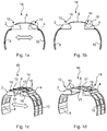
- first device components 2 and 4 are shown, on which a first surface element 6 and in each case a second surface element 8 and 10 is arranged.
- the first device components 2 and 4 are designed in the illustrated embodiment as overhead storage compartments, as they are commonly found in passenger cabins of aircraft.
- the first device components 2 and 4 have on their respective upper side 12 and 14 respectively a plurality, for example four, realized as guide rails guide elements 16, which are preferably arranged in the extension of stiffening ribs 17 of the first surface element 6, where the stiffening ribs 17 on the top 12 or 14 meet.
- This composite can be referred to as cabin module 18.
- a mounting position can be seen, in which the ends of the surface element 6 are arranged in a relatively far outer region of the guide member 16.
- the width of the cabin module 18 is thereby as small as possible, since the distance between the two first device components 2 and 4 and the two second surface elements 8 and 10 is reduced. This allows insertion of the cabin module 18 in an open vehicle body.
- a so-called operating position is assumed, in which the ends of the first surface element 6 are arranged in relatively far-lying areas of the guide elements 16.
- the first device components 2 and 4 and the second surface elements 8 and 10 are relatively far outside, so that the width of the cabin module 18 is significantly greater than in the mounting position.
- the adaptation of the second surface elements 8 and 10 to the inner contour of the vehicle body, the first device components 2 and 4 are also in their respective end position.
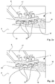
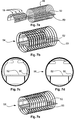
- the Fig. 2a and 2b show in a detailed view of a section of two juxtaposed guide elements 16 on an upper side 14 of a first device component 4, in which a plurality of oval or elongated shaped runners 20 are arranged and can move freely within the guide elements 16.
- the runners 20 are rotatably mounted on the first surface element 6 in the example shown and can by twisting from a first position, the in Fig. 2a is shown, in a second position, which Fig. 2b it will be apparent.
- Are the runners 20 as in Fig. 2b aligned is entered through the exemplary elongated shape of a positive and / or non-positive connection with appropriately shaped pockets 22 of the guide rail. This means that in this connection the first device component 4 and the first surface element 6 can no longer move relative to each other. This is helpful for reliably locking the first surface element 6 in an operating position or a mounting position.
- the operability of the rotor 20 from within the cabin module 18 is required.
- the first device component 2 or 4 could have an opening 19, through which a respective operating end of a rotor 20 can be reached.
- the runners 20 could be constructed so that a rotation of the respective rotor 20 is generated by a rectilinear pressure movement from the interior of a first device component 2 or 4 by a fitter or a suitable device, so that this brought from the locked into the sliding state becomes.
- a disassembly position can be taken in which the first surface element 6 occupies a very far outer region of the guide elements 16, so that when opened to the outside guide elements 16 Rotor 20 at the outer end of the guide element 16 can leave this and the first device component 4 can be dismantled accordingly.
- first device components 2 and 4 have a receiving surface 24 which is provided with hook-shaped first holding bodies 26.
- Second device components 28 can be fastened thereto, for example, as represented here, by the introduction or introduction of correspondingly shaped second holding bodies 30.
- one or more second device components 28 could represent a supply channel that could include control buttons, reading lamps, displays, air showers, and the like. This supply channel must be adapted to ensure ease of use and the different seating in the cabin and could be quickly changed by using the first holding body 26 shown on a receiving surface 24.
- the first holding body 26 could, for example, have a customs clearance with each other, which could correspond to the distance between two adjacent grid points in a seat rail in a cabin floor.
- the installation of a supply channel of a plurality of second device components 28 could take place in three essential steps.
- the first step the second device component 28 is raised to the receiving surface 24 and positioned exactly in the gaps of the first holding body 26.
- all the first holding bodies 26 are hooked into one another in a form-fitting manner with the corresponding second holding bodies 28.
- a frictional connection can be established by clamping.
- a latch in the form of a snap-action release mechanism at the end of a cabin module 18 could block the movement of all of the second device component 28 Prevent formed supply channel in the longitudinal and transverse direction.
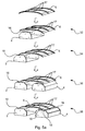
- a first surface element 6 is lifted in the form of a ceiling panel 32, 34 connected by means of a plurality of guide elements 16 with a first device component 2, then connected to another first device component 4 36 and finally in a mounting position locked 38 will.
- the composite of first surface element 6 and first device components 2 and 4 is lifted 40 so that a second surface element 8 is arranged 42 on the first device component 2 and a second surface element 10 is arranged 44 on the first device component 4.
- the cabin module 18 is completed and can be introduced in the illustrated assembly position in an open hull of a vehicle.
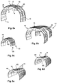
- a plurality of cabin modules 18 may be interconnected, such as by stringing them together and bracing them together by appropriate fasteners.
- the connection of the cabin modules 18 could take place in the region of the first device components 2 and 4, which have bores 46 for this, could be guided by the connecting elements and clamped accordingly.
- a composite of a plurality of cabin modules 18 can be incorporated into a designated body portion 48 of a vehicle.
- fasteners 50 realized in advance as floor rails are arranged on a floor structure 52 on which the modules 18 are to be mounted.
- the composite of several cabin modules 18 can be introduced into the fuselage section 54 and subsequently arrested 56 upon reaching the end position in an operating position. After securing 58 the modules 18, such as by connecting lower ends of the second surface elements 8 and 10 with the floor rails 50, the cabin of the vehicle is ready for use.
Landscapes
- Engineering & Computer Science (AREA)
- Aviation & Aerospace Engineering (AREA)
- Manufacturing & Machinery (AREA)
- Transportation (AREA)
- Body Structure For Vehicles (AREA)
- Vehicle Step Arrangements And Article Storage (AREA)
Claims (13)
- Système de fabrication d'une cabine de véhicule, comportant :- au moins un premier composant d'aménagement (2, 4),- au moins un premier élément de surface (6) réalisé sous la forme d'un panneau de plafond, et- au moins un élément de guidage (16),dans lequel le premier élément de surface (6) est disposé sur le premier composant d'aménagement (2, 4) de manière coulissante au moyen de l'élément de guidage (16) afin de former un module de cabine (18),
dans lequel l'élément de guidage (16) peut être bloqué dans au moins une position de montage et au moins une position de service,
dans lequel le module de cabine (18) comporte, en position de montage, des dimensions extérieures qui permettent une introduction dans une portion de fuselage (48) d'un véhicule et
dans lequel le module de cabine (18) forme, en position de service, au moins une portion d'une cabine dans la portion de fuselage (48) du véhicule. - Système selon la revendication 1,
comportant en outre des éléments de fixation (50) destinés à fixer le module de cabine (18) sur un plancher (52) dans la portion de fuselage (48). - Système selon la revendication 2,
dans lequel les éléments de fixation (50) sont réalisés sous la forme d'au moins un rail de plancher. - Système selon l'une des revendications précédentes, dans lequel l'élément de guidage (16) est réalisé sous la forme d'une combinaison d'un rail de guidage et d'au moins un curseur (20) mobile dans le rail de guidage.
- Système selon 1a revendication 4,
dans lequel l'au moins un curseur (20) possède une forme allongée, qui permet un déplacement du curseur (20) lorsque la direction d'extension du curseur (20) est orientée parallèlement au chemin de guidage du rail de guidage et qui bloque le curseur (20) dans le rail de guidage en cas d'orientation différente du curseur (20). - Système selon l'une des revendications précédentes, dans lequel l'élément de guidage (16) est configuré pour être actionné d'un endroit à l'intérieur du module de cabine (18).
- Système selon l'une des revendications précédentes, dans lequel au moins un premier composant d'aménagement (2, 4) comporte un orifice (19) pour bloquer ou débloquer l'élément de guidage (16).
- Système selon l'une des revendications précédentes, dans lequel le premier composant d'aménagement (2, 4) comporte au moins une surface de réception (24) dotée de premiers corps de retenue (26) espacés entre eux pour recevoir au moins un second composant d'aménagement (28).
- Système selon la revendication 8,
dans lequel le second composant d'aménagement (28) comporte des seconds corps de retenue (30) formés de manière correspondante pour établir une liaison avec les premiers corps de retenue (26). - Système selon l'une des revendications précédentes,
dans lequel un second élément de surface (8, 10) est réalisé sous la forme d'un élément d'habillage latéral. - Procédé de fabrication d'une cabine de véhicule, comportant les étapes consistant à :- lever (32) un premier élément de surface (6) réalisé sous la forme d'un panneau de plafond ;- relier (34, 36) le premier élément de surface (6) à au moins un premier composant d'aménagement (2, 4) au moyen d'au moins un élément de guidage (16) ;- bloquer (38) l'élément de guidage (16) dans une position de montage ;- lever (40) l'assemblage constitué du premier élément de surface (6) et du premier composant d'aménagement (2, 4) ;- disposer (42) au moins un second élément de surface (8, 10) sur le premier composant d'aménagement (2, 4) pour former un module de cabine (18) complet ;- introduire (54) le module de cabine (18) dans une portion de fuselage (48) du véhicule ;- bloquer (56) le module de cabine dans une position de service ;- fixer (58) le module de cabine dans la portion de fuselage (48).
- Utilisation d'un système selon l'une des revendications 1 à 10 dans une portion de fuselage (48) d'un aéronef.
- Aéronef, comportant :- au moins une portion de fuselage (48),- un plancher (52) disposé dans celle-ci, et au moins un- module de cabine (18)formé au moyen d'un système selon l'une des revendications 1 à 10,dans lequel le module de cabine (18) comporte au moins un premier composant d'aménagement (2, 4), au moins un premier élément de surface (6) réalisé sous la forme d'un panneau de plafond et au moins un élément de guidage (16), le premier élément de surface (6) étant disposé sur le premier composant d'aménagement (2, 4) de manière coulissante au moyen de l'élément de guidage (16) et l'élément de guidage (16) pouvant être bloqué dans au moins une position de montage et au moins une position de service, le module de cabine (18) formant, en position de service, au moins une portion d'une cabine dans la portion de fuselage (48).
Applications Claiming Priority (3)
| Application Number | Priority Date | Filing Date | Title |
|---|---|---|---|
| US18491609P | 2009-06-08 | 2009-06-08 | |
| DE102009024157A DE102009024157A1 (de) | 2009-06-08 | 2009-06-08 | System und Verfahren zum Herstellen einer Fahrzeugkabine |
| PCT/EP2010/057051 WO2010145915A1 (fr) | 2009-06-08 | 2010-05-21 | Système et procédé de fabrication d'une cabine de véhicule |
Publications (2)
| Publication Number | Publication Date |
|---|---|
| EP2440457A1 EP2440457A1 (fr) | 2012-04-18 |
| EP2440457B1 true EP2440457B1 (fr) | 2016-08-17 |
Family
ID=43355904
Family Applications (1)
| Application Number | Title | Priority Date | Filing Date |
|---|---|---|---|
| EP10722670.6A Not-in-force EP2440457B1 (fr) | 2009-06-08 | 2010-05-21 | Système et procédé de fabrication d'une cabine de véhicule |
Country Status (5)
| Country | Link |
|---|---|
| US (1) | US8534603B2 (fr) |
| EP (1) | EP2440457B1 (fr) |
| CN (1) | CN102458989B (fr) |
| DE (1) | DE102009024157A1 (fr) |
| WO (1) | WO2010145915A1 (fr) |
Families Citing this family (24)
| Publication number | Priority date | Publication date | Assignee | Title |
|---|---|---|---|---|
| EP1803645B1 (fr) * | 2005-12-29 | 2020-03-11 | Airbus Operations GmbH | Module pour un aéronef |
| DE102006048376B4 (de) * | 2006-10-12 | 2010-04-15 | Airbus Deutschland Gmbh | Freitragende Kabinenstruktur |
| WO2009124832A2 (fr) * | 2008-04-10 | 2009-10-15 | Airbus Operations Gmbh | Aéronef avec élément de transmission de forces entre un élément structural de cabine et une structure primaire |
| DE102010026683A1 (de) * | 2010-07-09 | 2012-01-12 | Airbus Operations Gmbh | Interieurkomponententrägersystem, Flugzeuginterieurkomponentenmodul und Montageverfahren |
| WO2012084205A2 (fr) | 2010-12-23 | 2012-06-28 | Airbus Operations Gmbh | Module et système de support de composants de système d'aéronef et procédé de montage |
| DE102011102364A1 (de) * | 2011-05-24 | 2012-11-29 | Airbus Operations Gmbh | Freitragendes Kabinenstruktursegment |
| US9090357B2 (en) * | 2011-12-15 | 2015-07-28 | The Boeing Company | Method of assembling panelized aircraft fuselages |
| AT513939A1 (de) | 2013-02-01 | 2014-08-15 | Facc Ag | Überkopf-Gepäckfach für Flugzeuge und Flugzeug mit solchen Überkopf-Gepäckfächern |
| CA152275S (en) | 2013-02-01 | 2014-08-18 | Facc Ag | Aircraft overhead bin |
| AT515159B1 (de) | 2013-11-20 | 2018-07-15 | Helikopter Air Transp Gmbh | Innenverkleidungsteil und Fertigteil - Baugruppe für eine Luftfahrzeugzelle |
| FR3033273B1 (fr) * | 2015-03-02 | 2017-08-18 | Airbus Operations Sas | Porte-outil fixe sur une piece |
| DE102015206707A1 (de) * | 2015-04-15 | 2016-10-20 | Airbus Operations Gmbh | Monument für eine Kabine eines Fahrzeugs und Befestigungsanordnung |
| FR3035075B1 (fr) * | 2015-04-20 | 2018-08-17 | Airbus Operations | Ensemble d'outillage pour l'integration d'une partie centrale d'aeronef, procede associe et aeronef ainsi integre |
| US10046843B2 (en) | 2015-05-27 | 2018-08-14 | The Boeing Company | Interior module installation in an aircraft fuselage |
| US10259559B2 (en) | 2015-08-31 | 2019-04-16 | The Boeing Company | Remotely-activated self-centering cable latch |
| US9758233B2 (en) | 2015-08-31 | 2017-09-12 | The Boeing Company | Support system having a crown integration panel (CIP) |
| US10011343B2 (en) | 2015-08-31 | 2018-07-03 | The Boeing Company | Self-aligning structural attachment for crown integration panel (CIP) |
| US10053204B2 (en) | 2015-08-31 | 2018-08-21 | The Boeing Company | Adjustable support structure for aircraft cabin ceiling |
| US10179638B2 (en) | 2015-08-31 | 2019-01-15 | The Boeing Company | Crown raceway support (CRS) for crown integration panel (CIP) |
| DE102017131150A1 (de) * | 2017-12-22 | 2019-06-27 | Airbus Operations Gmbh | Modulsystem zur Installation von Modulen an einer Rumpfstruktur eines Fahrzeugs |
| DE102019134746A1 (de) * | 2019-12-17 | 2021-06-17 | Airbus Operations Gmbh | Komponentensystem zur Innenausstattung eines Luftfahrzeugs |
| DE102021102132A1 (de) * | 2021-01-29 | 2022-08-04 | Airbus Operations Gmbh | Luftverteilungssystem für eine Kabine eines Luftfahrzeugs |
| CN114212272B (zh) * | 2021-12-17 | 2024-04-02 | 江西洪都航空工业集团有限责任公司 | 一种快速装卸机构 |
| EP4378837B1 (fr) * | 2022-11-30 | 2025-06-11 | Airbus Operations GmbH | Système d'installation et procédé d'installation d'une structure en treillis autoportante |
Family Cites Families (17)
| Publication number | Priority date | Publication date | Assignee | Title |
|---|---|---|---|---|
| DE3007733A1 (de) * | 1980-02-29 | 1981-09-10 | Aluminium-Walzwerke Singen Gmbh, 7700 Singen | Fluggeraet, insbesondere flugzeug, und transportbehaelter dafuer |
| US4799631A (en) * | 1987-02-18 | 1989-01-24 | Atr International, Inc. | Aircraft shell module |
| US5024398A (en) * | 1989-06-28 | 1991-06-18 | The Boeing Company | Office module for passenger aircraft |
| US5083727A (en) * | 1990-01-02 | 1992-01-28 | The Boeing Company | Aircraft cabin system for selectivley locating interior units |
| US5855291A (en) * | 1996-05-13 | 1999-01-05 | Ingle; Edward C. | Vehicle cargo restrainer |
| US6899299B2 (en) * | 2002-07-26 | 2005-05-31 | The Boeing Company | Luggage bins and aircraft passenger cabin ceilings |
| NL1022580C2 (nl) * | 2003-02-04 | 2004-08-05 | Skohold B V | Module voor plaatsing in een passagierscabine van een transportmiddel, meer in het bijzonder een vliegtuig. |
| US7270297B2 (en) * | 2004-01-30 | 2007-09-18 | The Boeing Company | Hoist for aircraft cabin construction |
| US20060101631A1 (en) * | 2004-11-17 | 2006-05-18 | World Shelters, Inc. | Method and equipment for manufacturing expandable and collapsible structures |
| US7237749B2 (en) * | 2004-12-14 | 2007-07-03 | The Boeing Company | Collapsible mobile platform interior structure |
| GB0512541D0 (en) * | 2005-06-20 | 2005-07-27 | James Park Associates Ltd | Aircraft interior module |
| DE102006017596B4 (de) | 2006-04-13 | 2015-03-05 | Airbus Operations Gmbh | Kabinenabteil und dessen Verwendung in einem Luftfahrzeug |
| US20070241231A1 (en) | 2006-04-13 | 2007-10-18 | Airbus Deutschland Gmbh | Cabin module and cabin compartment with such a cabin module |
| DE102006039291A1 (de) * | 2006-08-22 | 2008-03-13 | Airbus Deutschland Gmbh | Rahmenelement, Gepäckfach sowie Verfahren zur Montage eines Gepäckfachs in einem Flugzeug |
| DE102006048376B4 (de) | 2006-10-12 | 2010-04-15 | Airbus Deutschland Gmbh | Freitragende Kabinenstruktur |
| DE102007050422B4 (de) * | 2007-10-22 | 2012-03-08 | Airbus Operations Gmbh | Flugzeugkomponentenmontagesystem |
| WO2009124832A2 (fr) * | 2008-04-10 | 2009-10-15 | Airbus Operations Gmbh | Aéronef avec élément de transmission de forces entre un élément structural de cabine et une structure primaire |
-
2009
- 2009-06-08 DE DE102009024157A patent/DE102009024157A1/de not_active Ceased
-
2010
- 2010-05-21 EP EP10722670.6A patent/EP2440457B1/fr not_active Not-in-force
- 2010-05-21 WO PCT/EP2010/057051 patent/WO2010145915A1/fr not_active Ceased
- 2010-05-21 CN CN201080035191.5A patent/CN102458989B/zh not_active Expired - Fee Related
-
2011
- 2011-12-08 US US13/314,788 patent/US8534603B2/en not_active Expired - Fee Related
Also Published As
| Publication number | Publication date |
|---|---|
| CN102458989A (zh) | 2012-05-16 |
| US20120145828A1 (en) | 2012-06-14 |
| CN102458989B (zh) | 2015-07-08 |
| US8534603B2 (en) | 2013-09-17 |
| WO2010145915A1 (fr) | 2010-12-23 |
| EP2440457A1 (fr) | 2012-04-18 |
| DE102009024157A1 (de) | 2011-03-03 |
Similar Documents
| Publication | Publication Date | Title |
|---|---|---|
| EP2440457B1 (fr) | Système et procédé de fabrication d'une cabine de véhicule | |
| EP2493760B1 (fr) | Module compartiment de rangement doté d'un canal de service passagers intégré de montage optimisé | |
| EP2493761B1 (fr) | Module compartiment de rangement doté d'un compartiment de rangement mobile | |
| EP2563653B1 (fr) | Système de rails, et procédé et système pour monter une pièce dans un avion | |
| DE202011110232U1 (de) | Toilettenanordnung für ein Verkehrsmittel | |
| DE102008058271A1 (de) | Versorgungseinheit für flexible Versorgungskanäle | |
| EP3464067B1 (fr) | Système de siège de passager pour une cabine d'un moyen de transport | |
| DE102016110022B4 (de) | Sitzschienensystem für eine Kabine eines Fahrzeugs, Sitzanordnung und Fahrzeug | |
| DE102015117709A1 (de) | Adapterschienensystem und Verfahren zum Befestigen eines Objekts an einer Fußbodenschiene in einem Transportmittel | |
| DE102016104794A1 (de) | Trennwandmodul für eine Kabine eines Fahrzeugs zur optischen und mechanischen Abtrennung unterschiedlicher Kabinenbereiche | |
| EP2265492A1 (fr) | Système de fixation et procédé de fixation d un élément d un équipement intérieur d avion | |
| DE102018108190A1 (de) | Befestigungssystem für Passagiersitze in einer Kabine eines Fahrzeugs | |
| EP4126669B1 (fr) | Région de véhicule dotée d'un compartiment à bagages et d'un panneau de recouvrement au-dessus du compartiment à bagages, et procédé de montage et de démontage d'un panneau de recouvrement au-dessus du compartiment à bagages | |
| DE102016111999A1 (de) | Modulares Schienensystem mit Klemmbefestigung | |
| DE102019134746A1 (de) | Komponentensystem zur Innenausstattung eines Luftfahrzeugs | |
| DE102008048745A1 (de) | Arretiervorrichtung für ein an einer Schiene arretierbares Objekt | |
| EP3458362B1 (fr) | Système flexible de rail servant à fixer des objets au plancher d'une cabine d'un moyen de transport | |
| DE102007032235A1 (de) | Leichtes Schienensystem zur Krafteinleitung großer Lasten in eine Struktur | |
| DE102018103514A1 (de) | Befestigungssystem zum Befestigen von Einbauten an einer Schiene in einem Fahrzeug | |
| EP3718888A1 (fr) | Système de réception pour récipients roulants dans un véhicule ainsi que véhicule doté d'un tel système | |
| DE102016111983B4 (de) | Modulares Schienensystem | |
| DE102016106279B4 (de) | Anordnung in einer Kabine eines Flugzeugs sowie ein Flugzeug mit mindestens einer derartigen Anordnung | |
| DE102018115776A1 (de) | Sitzgestellbefestigungsbaugruppe, Sitzgestell, Fahrzeugabschnitt und Fahrzeug mit einer Sitzgestellbefestigungsbaugruppe | |
| DE102011112305A1 (de) | Sitzanordnung für ein Kraftfahrzeug mit einer Zwangsführung für einen Fahrzeugsitz | |
| DE102016111994A1 (de) | Modulares Schienensystem |
Legal Events
| Date | Code | Title | Description |
|---|---|---|---|
| PUAI | Public reference made under article 153(3) epc to a published international application that has entered the european phase |
Free format text: ORIGINAL CODE: 0009012 |
|
| 17P | Request for examination filed |
Effective date: 20111201 |
|
| AK | Designated contracting states |
Kind code of ref document: A1 Designated state(s): AL AT BE BG CH CY CZ DE DK EE ES FI FR GB GR HR HU IE IS IT LI LT LU LV MC MK MT NL NO PL PT RO SE SI SK SM TR |
|
| RIN1 | Information on inventor provided before grant (corrected) |
Inventor name: GROSSE-PLANKERMANN, PETER Inventor name: PAETZ, MARTIN Inventor name: JUNGE, PHILIPP |
|
| DAX | Request for extension of the european patent (deleted) | ||
| GRAP | Despatch of communication of intention to grant a patent |
Free format text: ORIGINAL CODE: EPIDOSNIGR1 |
|
| INTG | Intention to grant announced |
Effective date: 20160222 |
|
| GRAS | Grant fee paid |
Free format text: ORIGINAL CODE: EPIDOSNIGR3 |
|
| GRAA | (expected) grant |
Free format text: ORIGINAL CODE: 0009210 |
|
| AK | Designated contracting states |
Kind code of ref document: B1 Designated state(s): AL AT BE BG CH CY CZ DE DK EE ES FI FR GB GR HR HU IE IS IT LI LT LU LV MC MK MT NL NO PL PT RO SE SI SK SM TR |
|
| REG | Reference to a national code |
Ref country code: GB Ref legal event code: FG4D Free format text: NOT ENGLISH |
|
| REG | Reference to a national code |
Ref country code: CH Ref legal event code: EP |
|
| REG | Reference to a national code |
Ref country code: IE Ref legal event code: FG4D Free format text: LANGUAGE OF EP DOCUMENT: GERMAN |
|
| REG | Reference to a national code |
Ref country code: AT Ref legal event code: REF Ref document number: 820788 Country of ref document: AT Kind code of ref document: T Effective date: 20160915 |
|
| REG | Reference to a national code |
Ref country code: DE Ref legal event code: R096 Ref document number: 502010012218 Country of ref document: DE |
|
| REG | Reference to a national code |
Ref country code: NL Ref legal event code: MP Effective date: 20160817 |
|
| REG | Reference to a national code |
Ref country code: LT Ref legal event code: MG4D |
|
| PG25 | Lapsed in a contracting state [announced via postgrant information from national office to epo] |
Ref country code: IT Free format text: LAPSE BECAUSE OF FAILURE TO SUBMIT A TRANSLATION OF THE DESCRIPTION OR TO PAY THE FEE WITHIN THE PRESCRIBED TIME-LIMIT Effective date: 20160817 Ref country code: NL Free format text: LAPSE BECAUSE OF FAILURE TO SUBMIT A TRANSLATION OF THE DESCRIPTION OR TO PAY THE FEE WITHIN THE PRESCRIBED TIME-LIMIT Effective date: 20160817 Ref country code: HR Free format text: LAPSE BECAUSE OF FAILURE TO SUBMIT A TRANSLATION OF THE DESCRIPTION OR TO PAY THE FEE WITHIN THE PRESCRIBED TIME-LIMIT Effective date: 20160817 Ref country code: LT Free format text: LAPSE BECAUSE OF FAILURE TO SUBMIT A TRANSLATION OF THE DESCRIPTION OR TO PAY THE FEE WITHIN THE PRESCRIBED TIME-LIMIT Effective date: 20160817 Ref country code: NO Free format text: LAPSE BECAUSE OF FAILURE TO SUBMIT A TRANSLATION OF THE DESCRIPTION OR TO PAY THE FEE WITHIN THE PRESCRIBED TIME-LIMIT Effective date: 20161117 Ref country code: FI Free format text: LAPSE BECAUSE OF FAILURE TO SUBMIT A TRANSLATION OF THE DESCRIPTION OR TO PAY THE FEE WITHIN THE PRESCRIBED TIME-LIMIT Effective date: 20160817 |
|
| PG25 | Lapsed in a contracting state [announced via postgrant information from national office to epo] |
Ref country code: PT Free format text: LAPSE BECAUSE OF FAILURE TO SUBMIT A TRANSLATION OF THE DESCRIPTION OR TO PAY THE FEE WITHIN THE PRESCRIBED TIME-LIMIT Effective date: 20161219 Ref country code: SE Free format text: LAPSE BECAUSE OF FAILURE TO SUBMIT A TRANSLATION OF THE DESCRIPTION OR TO PAY THE FEE WITHIN THE PRESCRIBED TIME-LIMIT Effective date: 20160817 Ref country code: LV Free format text: LAPSE BECAUSE OF FAILURE TO SUBMIT A TRANSLATION OF THE DESCRIPTION OR TO PAY THE FEE WITHIN THE PRESCRIBED TIME-LIMIT Effective date: 20160817 Ref country code: PL Free format text: LAPSE BECAUSE OF FAILURE TO SUBMIT A TRANSLATION OF THE DESCRIPTION OR TO PAY THE FEE WITHIN THE PRESCRIBED TIME-LIMIT Effective date: 20160817 Ref country code: GR Free format text: LAPSE BECAUSE OF FAILURE TO SUBMIT A TRANSLATION OF THE DESCRIPTION OR TO PAY THE FEE WITHIN THE PRESCRIBED TIME-LIMIT Effective date: 20161118 Ref country code: ES Free format text: LAPSE BECAUSE OF FAILURE TO SUBMIT A TRANSLATION OF THE DESCRIPTION OR TO PAY THE FEE WITHIN THE PRESCRIBED TIME-LIMIT Effective date: 20160817 |
|
| PG25 | Lapsed in a contracting state [announced via postgrant information from national office to epo] |
Ref country code: EE Free format text: LAPSE BECAUSE OF FAILURE TO SUBMIT A TRANSLATION OF THE DESCRIPTION OR TO PAY THE FEE WITHIN THE PRESCRIBED TIME-LIMIT Effective date: 20160817 Ref country code: RO Free format text: LAPSE BECAUSE OF FAILURE TO SUBMIT A TRANSLATION OF THE DESCRIPTION OR TO PAY THE FEE WITHIN THE PRESCRIBED TIME-LIMIT Effective date: 20160817 |
|
| REG | Reference to a national code |
Ref country code: DE Ref legal event code: R097 Ref document number: 502010012218 Country of ref document: DE |
|
| REG | Reference to a national code |
Ref country code: FR Ref legal event code: PLFP Year of fee payment: 8 |
|
| PG25 | Lapsed in a contracting state [announced via postgrant information from national office to epo] |
Ref country code: SM Free format text: LAPSE BECAUSE OF FAILURE TO SUBMIT A TRANSLATION OF THE DESCRIPTION OR TO PAY THE FEE WITHIN THE PRESCRIBED TIME-LIMIT Effective date: 20160817 Ref country code: CZ Free format text: LAPSE BECAUSE OF FAILURE TO SUBMIT A TRANSLATION OF THE DESCRIPTION OR TO PAY THE FEE WITHIN THE PRESCRIBED TIME-LIMIT Effective date: 20160817 Ref country code: BG Free format text: LAPSE BECAUSE OF FAILURE TO SUBMIT A TRANSLATION OF THE DESCRIPTION OR TO PAY THE FEE WITHIN THE PRESCRIBED TIME-LIMIT Effective date: 20161117 Ref country code: SK Free format text: LAPSE BECAUSE OF FAILURE TO SUBMIT A TRANSLATION OF THE DESCRIPTION OR TO PAY THE FEE WITHIN THE PRESCRIBED TIME-LIMIT Effective date: 20160817 Ref country code: DK Free format text: LAPSE BECAUSE OF FAILURE TO SUBMIT A TRANSLATION OF THE DESCRIPTION OR TO PAY THE FEE WITHIN THE PRESCRIBED TIME-LIMIT Effective date: 20160817 |
|
| PLBE | No opposition filed within time limit |
Free format text: ORIGINAL CODE: 0009261 |
|
| STAA | Information on the status of an ep patent application or granted ep patent |
Free format text: STATUS: NO OPPOSITION FILED WITHIN TIME LIMIT |
|
| 26N | No opposition filed |
Effective date: 20170518 |
|
| PG25 | Lapsed in a contracting state [announced via postgrant information from national office to epo] |
Ref country code: SI Free format text: LAPSE BECAUSE OF FAILURE TO SUBMIT A TRANSLATION OF THE DESCRIPTION OR TO PAY THE FEE WITHIN THE PRESCRIBED TIME-LIMIT Effective date: 20160817 Ref country code: LU Free format text: LAPSE BECAUSE OF NON-PAYMENT OF DUE FEES Effective date: 20170531 |
|
| REG | Reference to a national code |
Ref country code: CH Ref legal event code: PL |
|
| GBPC | Gb: european patent ceased through non-payment of renewal fee |
Effective date: 20170521 |
|
| PG25 | Lapsed in a contracting state [announced via postgrant information from national office to epo] |
Ref country code: MC Free format text: LAPSE BECAUSE OF FAILURE TO SUBMIT A TRANSLATION OF THE DESCRIPTION OR TO PAY THE FEE WITHIN THE PRESCRIBED TIME-LIMIT Effective date: 20160817 |
|
| REG | Reference to a national code |
Ref country code: IE Ref legal event code: MM4A |
|
| PG25 | Lapsed in a contracting state [announced via postgrant information from national office to epo] |
Ref country code: LI Free format text: LAPSE BECAUSE OF NON-PAYMENT OF DUE FEES Effective date: 20170531 Ref country code: CH Free format text: LAPSE BECAUSE OF NON-PAYMENT OF DUE FEES Effective date: 20170531 |
|
| PG25 | Lapsed in a contracting state [announced via postgrant information from national office to epo] |
Ref country code: LU Free format text: LAPSE BECAUSE OF NON-PAYMENT OF DUE FEES Effective date: 20170521 |
|
| REG | Reference to a national code |
Ref country code: BE Ref legal event code: MM Effective date: 20170531 |
|
| PG25 | Lapsed in a contracting state [announced via postgrant information from national office to epo] |
Ref country code: GB Free format text: LAPSE BECAUSE OF NON-PAYMENT OF DUE FEES Effective date: 20170521 Ref country code: IE Free format text: LAPSE BECAUSE OF NON-PAYMENT OF DUE FEES Effective date: 20170521 |
|
| REG | Reference to a national code |
Ref country code: FR Ref legal event code: PLFP Year of fee payment: 9 |
|
| REG | Reference to a national code |
Ref country code: AT Ref legal event code: MM01 Ref document number: 820788 Country of ref document: AT Kind code of ref document: T Effective date: 20170521 |
|
| PG25 | Lapsed in a contracting state [announced via postgrant information from national office to epo] |
Ref country code: AT Free format text: LAPSE BECAUSE OF NON-PAYMENT OF DUE FEES Effective date: 20170521 Ref country code: BE Free format text: LAPSE BECAUSE OF NON-PAYMENT OF DUE FEES Effective date: 20170531 |
|
| PG25 | Lapsed in a contracting state [announced via postgrant information from national office to epo] |
Ref country code: MT Free format text: LAPSE BECAUSE OF FAILURE TO SUBMIT A TRANSLATION OF THE DESCRIPTION OR TO PAY THE FEE WITHIN THE PRESCRIBED TIME-LIMIT Effective date: 20160817 |
|
| PG25 | Lapsed in a contracting state [announced via postgrant information from national office to epo] |
Ref country code: AL Free format text: LAPSE BECAUSE OF FAILURE TO SUBMIT A TRANSLATION OF THE DESCRIPTION OR TO PAY THE FEE WITHIN THE PRESCRIBED TIME-LIMIT Effective date: 20160817 |
|
| PG25 | Lapsed in a contracting state [announced via postgrant information from national office to epo] |
Ref country code: HU Free format text: LAPSE BECAUSE OF FAILURE TO SUBMIT A TRANSLATION OF THE DESCRIPTION OR TO PAY THE FEE WITHIN THE PRESCRIBED TIME-LIMIT; INVALID AB INITIO Effective date: 20100521 |
|
| PG25 | Lapsed in a contracting state [announced via postgrant information from national office to epo] |
Ref country code: CY Free format text: LAPSE BECAUSE OF NON-PAYMENT OF DUE FEES Effective date: 20160817 |
|
| PG25 | Lapsed in a contracting state [announced via postgrant information from national office to epo] |
Ref country code: MK Free format text: LAPSE BECAUSE OF FAILURE TO SUBMIT A TRANSLATION OF THE DESCRIPTION OR TO PAY THE FEE WITHIN THE PRESCRIBED TIME-LIMIT Effective date: 20160817 |
|
| PG25 | Lapsed in a contracting state [announced via postgrant information from national office to epo] |
Ref country code: TR Free format text: LAPSE BECAUSE OF FAILURE TO SUBMIT A TRANSLATION OF THE DESCRIPTION OR TO PAY THE FEE WITHIN THE PRESCRIBED TIME-LIMIT Effective date: 20160817 |
|
| PG25 | Lapsed in a contracting state [announced via postgrant information from national office to epo] |
Ref country code: IS Free format text: LAPSE BECAUSE OF FAILURE TO SUBMIT A TRANSLATION OF THE DESCRIPTION OR TO PAY THE FEE WITHIN THE PRESCRIBED TIME-LIMIT Effective date: 20161217 |
|
| PGFP | Annual fee paid to national office [announced via postgrant information from national office to epo] |
Ref country code: FR Payment date: 20220523 Year of fee payment: 13 Ref country code: DE Payment date: 20220519 Year of fee payment: 13 |
|
| REG | Reference to a national code |
Ref country code: DE Ref legal event code: R119 Ref document number: 502010012218 Country of ref document: DE |
|
| PG25 | Lapsed in a contracting state [announced via postgrant information from national office to epo] |
Ref country code: DE Free format text: LAPSE BECAUSE OF NON-PAYMENT OF DUE FEES Effective date: 20231201 |
|
| PG25 | Lapsed in a contracting state [announced via postgrant information from national office to epo] |
Ref country code: FR Free format text: LAPSE BECAUSE OF NON-PAYMENT OF DUE FEES Effective date: 20230531 |